Samsung Electronics Co SAM335 ADSL Modem User Manual
Samsung Electronics Co Ltd ADSL Modem
User manual

English

iii
Class B Digital Device or Peripheral
This equipment has been tested and found to comply with the limits for a Class B digital
device, pursuant to Part 15 of the FCC Rules. These limits are designed to provide
reasonable protection against harmful interference in a residential installation. This
equipment generates, uses and can radiate radio frequency energy and, if not installed
and used in accordance with the instructions, may cause harmful interference to radio
communications. However, there is no guarantee that interference will not occur in a
particular installation. If this equipment does cause harmful interference to radio or
television reception, which can be determined by turning the equipment off and on, the
user is encouraged to try to correct the interference by one or more of the following
measures:
-Reorient or relocate the receiving antenna.
-Increase the separation between the equipment and receiver.
-Connect the equipment into an outlet on a circuit different from that to which the
receiver is connected.
-Consult the dealer or experienced radio TV technician for help.
Before Starting
This manual is for AceLink ADSL modem users. This book includes from the
introduction to installation, and problem solutions.
We recommend that the user read this guide carefully before operation of equipment.
If already familiar with the ADSL modem or similar systems, please read the notices in
the explanations for review.
If you encounter any problems or have any questions, please contact the service
provider.
CAUTION: Changes or modifications not expressly approved by the manufacturer
responsible for compliance could void the user's authority to operate the equipment

iv
About Manual
Following contents are described in each chapter of AceLink ADSL modem manual.
Chapter 1 ‘Introduction’ describes the main functions of the AceLink ADSL modem,
as well as its applications, hardware structure, and specifications
Chapter 2 ‘AceLink ADSL Modem Setup’ examines what the user must know
before installation, and describes the AceLink ADSL modem setting
environment and connection to network.
Appendix A ‘Troubleshooting’ describes major problems in using the AceLink ADSL
modem, and solutions.
Appendix B ‘Cable Specifications’ describes every sort of cable specification that is
needed for installation of AceLink ADSL modem.
Appendix C ‘Description of Terms’ explains terminology that you need to know
during the use of AceLink ADSL modem.

v
Contents
Chapter 1 Introduction ...............................................1-1~1-7
Introduction to AceLink ADSL modem ................................................1-2
Name and Function of each part...........................................................1-3
Front View................................................................................................. 1-3
Rear View..................................................................................................1-4
AceLink ADSL modem specifications...................................................1-5
Software Specifications
............................................................................... 1-7
Chapter 2 AceLink ADSL Modem Setup.....................2-1~2-13
Before Installation ................................................................................. 2-2
Safety Check............................................................................................. 2-2
Service Environment Check.................................................................... 2-3
Preparing cables.....................................................................................2-4
Modem Setting Environment................................................................... 2-6
Checking the Contents...........................................................................2-7
Modem Setup .........................................................................................2-8
1. Drawing the Network Configuration.................................................... 2-9
2. Power Disconnection.......................................................................... 2-10
3. Connecting Ethernet Cables.............................................................. 2-10
4. POTS Micro-filter Connection........................................................... 2-11
5. Power Connection............................................................................... 2-12
6. Checking all the Connections............................................................. 2-13
Appendix
A Troubleshooting.........................................A-1~A-3
Points You Must Know before Inquiring at the Place Where
You Purchased........................................................................................A-1
Troubleshooting - Problems and Solution .............................................A-2
Appendix
B Cable Specifications...................................B-1~B-3
Twisted pair Category-3,4,5 Straight-through Ethernet Cable...............B-1
Telephone Cable (RJ-11)...........................................................................B-3
Appendix
C Description of Terms.................................. C-1~C-4

vi
Figure Contents
Figure 1-1 Front view of AceLink ADSL modem.............................................................. 1-3
Figure 1-2 Rear view of AceLink ADSL modem................................................................ 1-4
Figure 2-1 RJ-11 telephone cable........................................................................................ 2-5
Figure 2-2 RJ-45 UTP Ethernet Cable ...............................................................................2-5
Figure 2-3 AceLink modem package.................................................................................. 2-7
Figure 2-4 Example of network configuration.................................................................... 2-9
Figure 2-5 Ethernet Cable Connection............................................................................. 2-10
Figure 2-6 POTS micro-filter connection.........................................................................2-11
Figure 2-7 Power adapter connection...............................................................................2-12
Figure B-1 Twisted pair Category-3,4,5 Straight-through cable.......................................B-1
Figure B-2 Twisted pair Category-3,4,5 Straight-through cable connector signal...........B-2
Figure B-3 Pin connection of Twisted pair Category-3,4,5 Straight-through
cable connector .................................................................................................B-2
Figure B-4 RJ-11 telephone cable.......................................................................................B-3

vii
Table Contents
Table 1-1 AceLink ADSL modem's LED functions............................................................ 1-3
Table 1-2 AceLink ADSL modem's port functions............................................................. 1-4
Table 1-3 Hardware specifications of AceLink ADSL modem ..........................................1-5
Table 1-4 DMT specifications of AceLink ADSL modem..................................................1-6
Table 1-5 Specifications of external connector of AceLink ADSL modem.......................1-6
Table 1-6 Specifications of external connector of AceLink ADSL modem.......................1-6
Table 1-7 Specifications of AceLink ADSL modem software............................................ 1-7
Table B-1 Pin connection of RJ-11 telephone cable connector..........................................B-3


1-1
Chapter 1Introduction
This chapter describes the main functions of the AceLink ADSL modem, as well as its
applications, hardware structure, and specifications.
yIntroduction to the AceLink ADSL modem
yName and function of each component
yAceLink ADSL modem specifications

1-2 Chapter 1
Introduction
Introduction to AceLink ADSL modem
It is possible to access the Internet and other multimedia service networks through an
existing telephone line (PSTN) using AceLink ADSL modem.
Unlike previous dial-up modems, AceLink ADSL modems provide the fastest speed
available as well as allow use of the telephone at the same time.
Characteristics of AceLink ADSL modem;
Various Applications
Some of the applications of AceLink ADSL modem include Internet access, chatting
(real-time communication), file transfers, and data download/upload.
Inexpensive Price
AceLink ADSL modem uses a pre-existing phone line (PSTN) instead of using a
separate cable, which needs a great amount of money and time to install.
Reliable Network Connection
AceLink ADSL modem operates in connection with the master system in the local
telephone office letting the telephone office manage all of the networking services.
Easy Installation
AceLink ADSL modem is easy install so that a popular user can easily connect to ISP
and receive the internet service.
Web-based Management
AceLink ADSL modem provides a web environment management function. Whereby,
the user can monitor the modem’s state and change the settings easily.
1-3
Name and Function of each part
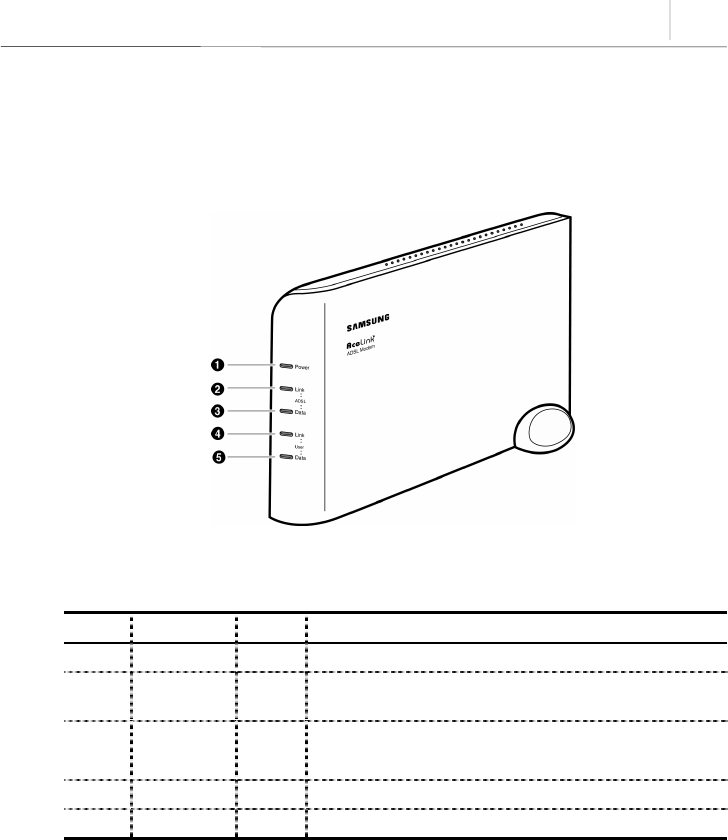
Front View
Figure 1-1 Front view of AceLink ADSL modem
Number Label Color Function
❶Power Green On, while AC power is provided.
❷Link(ADSL) Green On, while connected to telephone office’s ADSL master
system.
❸Data(ADSL) Green Flashing, when sending/receiving to/from telephone
office’s ADSL master system.
❹Link(User) Green On, while connected to PC.
❺Data(User) Green Flashing, when sending/receiving data through PC.
Table 1-1 AceLink ADSL modem's LED functions
1-4 Chapter 1
Introduction
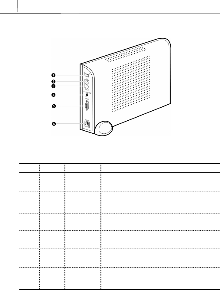
Rear View
Figure 1-2 Rear view of AceLink ADSL modem
Number Label Port Function
❶Off / On Power Switch A power switch of AceLink ADSL Modem.
❷ADSL ADSL line
port
Connect RJ-11 telephone line from the telephone
socket on the wall. This port is used to send/receive
ADSL data.
❸Phone Telephone
port Connected to ordinary telephone through micro-filter.
❹DC 5V Power input
port A jack to connect Input power (AC 110V, DC 5V
adapter) to ADSL modem.
❺Console Serial port
(RS232C) Used for maintenance of ADSL by technician.
❻Ethernet Ethernet port Connect to PC’s network adapter by using UTP.
Category-3,4,5 Straight-through cable. Provide up to
10Mbps speed.
Table 1-2 AceLink ADSL modem's port functions

1-5
AceLink ADSL modem specifications
Hardware Features
Category Specification
Power Supply
of Main Board
y Input Power : DC 5V (5V/1.5A)
y Voltage usable : 3.3V and 12V
y Power consumed : 4.5Watts (Max)
Power Supply
Adapter
y Rated Input : AC 110V, 60Hz
y Rated Output : DC +5.0V 1.5A
User Interface
y ADSL Interface(RJ-11) : Telephone line
y Telephone Interface(RJ-11) : Telephone
y Ethernet Interface(RJ-45) : Connection to 10Mbps Ethernet Port
(Straight-through)
y Console Interface(DB-9:Female) : 19,600bps Null modem interface
LED
y Power : A green light is on during normal operation of the modem.
y Link (ADSL) : A green light is on when it is linked to ADSL home
system network.
y Data (ADSL) : A green light flickers during transmitting/receiving of
data with ADSL home system network.
y Link (User) : A green light is on when it is linked to Ethernet port
of PC.
y Data (User) : A green light is on during transmitting/receiving of
data with PC.
Package
y Package Material : Plastic
y Dimension : 37(width) x 233(length) x 164.2(height) mm
y Weight : 1 Kg (modem, power supply device and cables are
included)
y Installation : Vertical installation is available (an installation rack is
provided).
Table 1-3 Hardware specifications of AceLink ADSL modem
1-6 Chapter 1
Introduction
DMT Specifications
Category Down Stream Up stream Remarks
Max Data Rate 8Mbps 640Kbps
접속 DSLAM 및
전송거리에 따
라 차이가 있을
수 있습니다.
ADSL OverHead 96Kbps 32Kbps Frame Mode 3
Bandwidth 0.11Mhz ~ 1.1Mhz 30Khz ~ 110Khz
TX Power 20dBm 12dBm
Bin Width 4.3125Khz T1.413 standard
(+/-50ppm)
Max Sym/bin 16 Bit
Latency Fast channel : < 2ms, Interleaved < 20ms
Applied Standard ANSI/T1.413, ITU-T/G.992.1, ITU-
T/G.992.2
Table 1-4 DMT specifications of AceLink ADSL modem
External Connector Specifications
Type Options Remarks
RJ-45 Ethernet y Internet access available by connecting to external
PC
RJ-11 Telephone
Line
y Telephone access available through external micro-
filter
RJ-11 ADSL Line y Connected to external ADSL line
Power Jack y AC/DC converter 5V adapter
Power Switch y Power On/Off switch
Table 1-5 Specifications of external connector of AceLink ADSL modem
Other Specifications
Content Item Remarks
Working Temp. 0 ~ 45℃
Telephone Service Linked to telephone using external micro-filter
Foreign Standard Form approval(EMI CLASS B)
U.S. FCC Part 15 & 68
Table 1-6 Specifications of external connector of AceLink ADSL modem
1-7
Software Specifications
Category Specification Remarks
Access Mode
y PPPoA mode (RFC2364 - PPP Over ATM)
y IPoA mode (RFC 1483 Routed Mode)
y RFC 1483 Bridged mode
y PPPoE mode (RFC 1516-PPP Over Ethernet)
y PPTP mode
Routing
Additional
Function
y IP routing
y NAT
y DHCP server
Management
Function
y CLI (Command Line Interpreter)
y Telnet
y SNMP agent
y Setup of web environment
y Software upgrade
y Traffic statistics monitoring
Table 1-7 Specifications of AceLink ADSL modem software
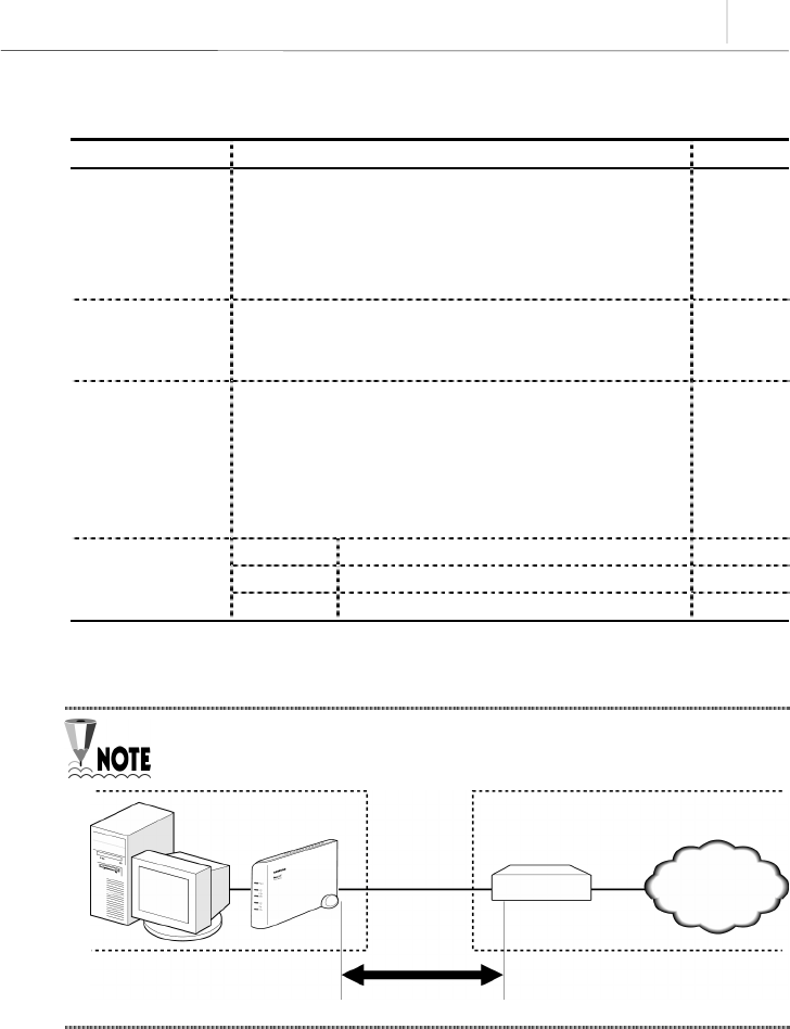
AceLink ADSL modem's speed can vary depending on length and
characterics of the line between DSLAM and modem.
Home Telephone Office
PC ADSL modem
DSLAM
Internet
modem-DSLAM


2-1
Chapter 2AceLink ADSL Modem Setup
This chapter introduces the environment where AceLink ADSL modem can be installed
and explains how to install this product and link it to a network.
This chapter consists of the following contents.
yBefore installation
yChecking the Contents
yModem Setup

2-2 Chapter 2
AceLink ADSL Modem Setup
Before Installation
This chapter examines what the user must know before installation.
Before installation of your ADSL modem follow the directions described in this chapter.
Safety Check
Before proceeding with the installation of the AceLink ADSL modem, user must check
the following categories.
Electricity Safety check
yThe user should not remove or open the product’s cover, it is especially dangerous
when the power is on.
yCheck and make sure if there are any flammable, electric conducting objects around
the modem. Make sure that there are no wet objects around. And check if the cable is
not worn out and other electrical devices around the modem are properly grounded.
Location check
yElectrical products tend to generate heat during operation. It is possible that if the
environment does not provide enough ventilation it would result in improper function
of the modem. Make sure that the modem is exposed to circulating air.
yCheck if the power is properly provided. If it happens to cause sparks or noise, be sure
to install a voltage regulator.

2-3
Service Environment Check
Check the followings before installing your AceLink ADSL modem.
Telephone network service
The AceLink ADSL modem should be installed where telephone network
service is available.
If there is no telephone line available in your area, be sure to report to the local
telephone office to construct a telephone line.
The telephone network service must support ADSL modem connection.
Some of the telephone network services will support ADSL applications. Check with
your local telephone office for subscription of ADSL.
PC Specification Check
In order to use AceLink ADSL modem by connecting to a PC, a LAN card (10Base-T or
10/100Base-T network adapter) must be installed in your PC. You can purchase the LAN
card at any PC shop.
Using the USB port on the SAM-335U model requires a higher version
operating system than Windows 98 SE (Second Edition).
2-4 Chapter 2
AceLink ADSL Modem Setup
Preparing cables
You must have all cables ready before connecting to the network. The following cables
are needed to connect the AceLink ADSL modem to the network.
Port Required cable
Telephone line port (PHONE) RJ-11 telephone cables.
Ethernet port (10BASE-T) RJ-45 UTP Category-3,4,5 Straight-through cable.
Table 2-1 Cables used by AceLink ADSL modem
A console port connection cable is not provided with the product.
2-5
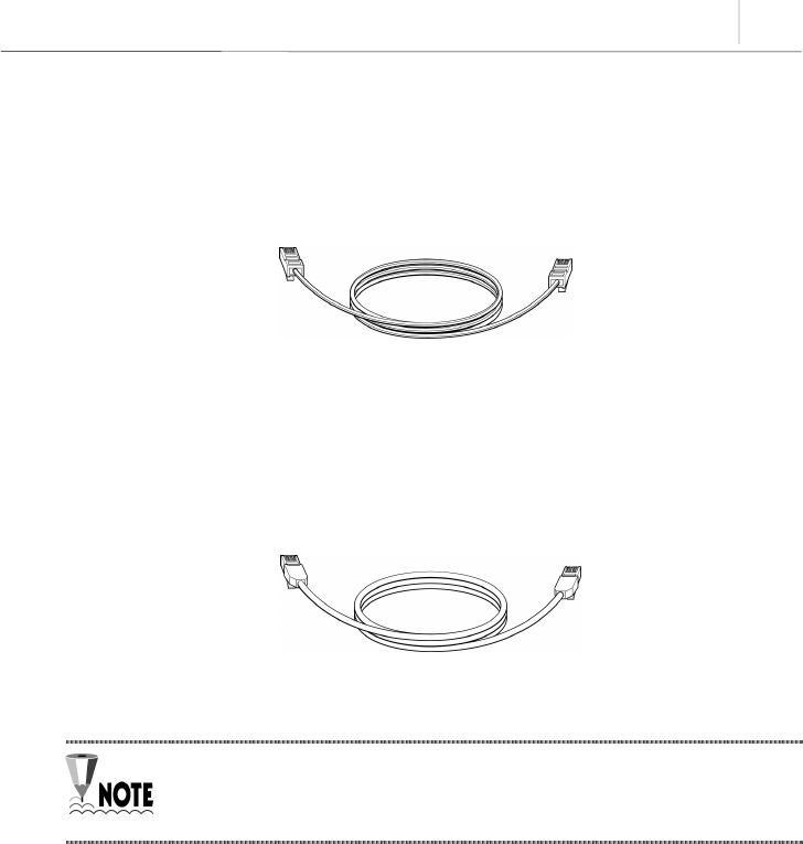
RJ-11 telephone cable
One end of the RJ-11 telephone cable is connected to telephone line port (phone) in the
back of the AceLink ADSL modem, and the other is connected to the POTS micro-filter
(LINE) which is provided separately.
Figure 2-1 RJ-11 telephone cable
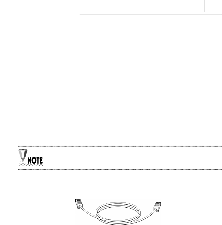
RJ-45 UTP Ethernet cable
Connect one end of the RJ-45 UTP Ethernet cable to the Ethernet port (10BASE-T)
which is at the rear plane of AceLink ADSL modem and connect the other end to the
LAN card of the PC.
Figure 2-2 RJ-45 UTP Ethernet Cable
Cables may look alike, however they could be different, for example they
could have different inner pins. Therefore, in order not to use them with
other cables, it is recommended to label each cable.

2-6 Chapter 2
AceLink ADSL Modem Setup
Modem Setting Environment
For safe installation, let’s examine the AceLink ADSL modem setting environment.
The AceLink ADSL modem should be kept at moderate temperature and humidity.
The recommended environment is as follows:
y Temperature : 0 ~ 45℃
y Relative humidity : 10 ~ 90% (uncondensed)
y Power : 4.5 Watts (maximum)
y Input power : AC 110V, DC 5V
y Frequency : 60Hz
The voltage variation of the power input during operation should be within
5 % of regulatory voltage. The electrical outlet should be grounded. Also,
the AceLink ADSL modem's power connecter should not be used on the
same outlet where a hair dryer, iron or refrigerator is connected. To
provide a stable power supply, an AVR (Automatic Voltage Regulator) is
recommended to be used.
2-7
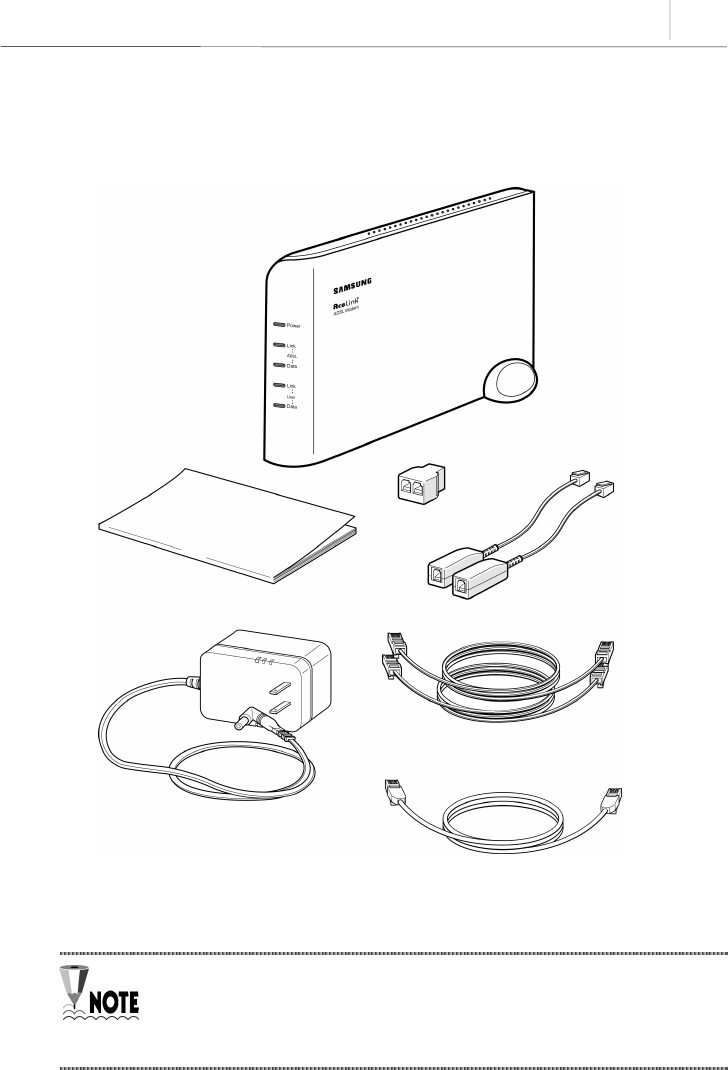
Checking the Contents
After purchasing your AceLink ADSL modem package, open the box and check if all the
following contents are included.
Figure 2-3 AceLink modem package
A POTS micro-filter is needed to use the ordinary telephone service and
ADSL data service at the same time. You need to prepare a POTS micro-
filter for each telephone used in your home. Ask your AceLink ADSL
modem provider about purchasing additional POTS micro-filters.
A
ceLink ADSL Modem
POTS Micro-filter 그림도 한 개로
수정
User Guide
Power Adapter
RJ-45 UTP Ethernet Cable
RJ-11 Telephone Cabel 그림도 한 개로 수정
Y Jack

2-8 Chapter 2
AceLink ADSL Modem Setup
Modem Setup
We will go over how to configure your AceLink ADSL modem.
Configuration procedures are as follows :
1. Drawing the network configuration
2. Power disconnection
3. Ethernet Cable connection
4. POTS micro-filter connection
5. Power connection
6. Checking all the connections
Each step is described in detail below.
2-9
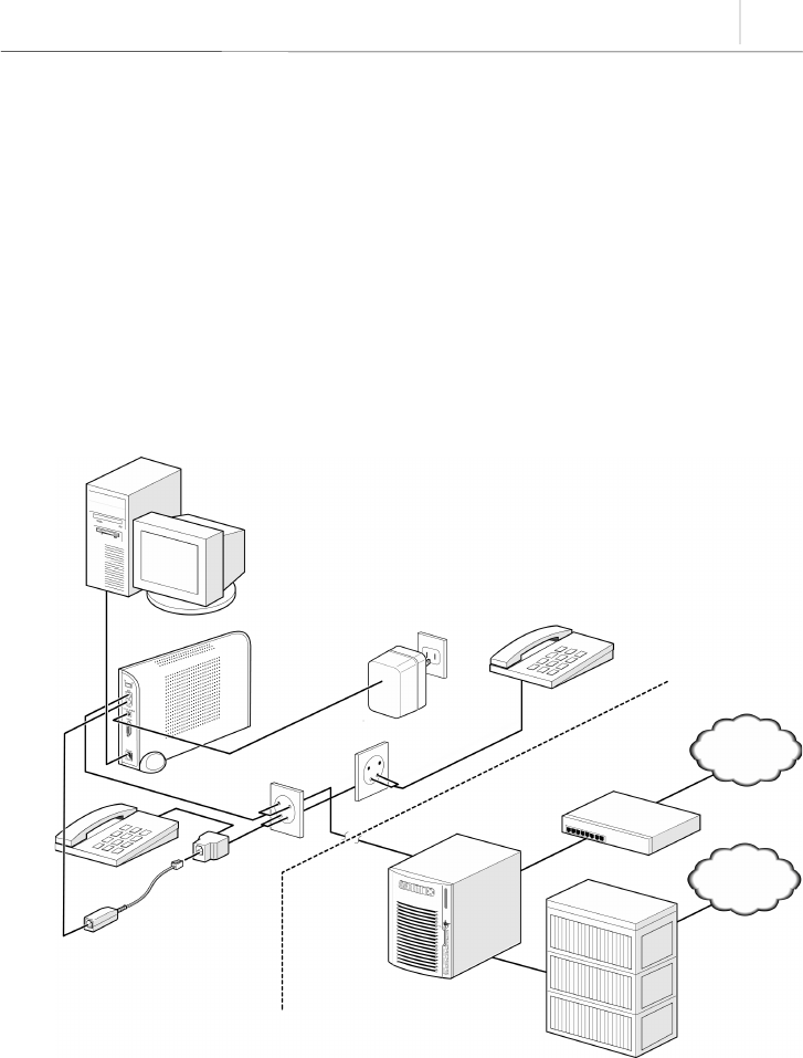
1. Drawing the Network Configuration
First, it is better to draw a network configuration for the AceLink ADSL modem. You
must consider the following matters when drawing a network configuration.
yWhat will the AceLink ADSL modem are used for?
yAre you going to use the AceLink ADSL modem and telephone at the same time?
yHave you prepared all the necessary equipment such as PC, POTS micro-filter,
telephone, and network cable?
The diagram below is an example configuration of an AceLink modem to PC, POTS
micro-filter and telephone. Draw your own configuration in reference with this diagram.
Figure 2-4 Example of network configuration
Internet
PSTN
Subscriber's home telephone network
PC AC 110V Telephone #2
POTS Micro-filter #1
Router
Switch System
AceLink ADSL system
(DSLAM)
LINE
LINE
10Base-T
A
DSL modem
Telephone #1
2-10 Chapter 2
AceLink ADSL Modem Setup
2. Power Disconnection
If power is supplied to the AceLink ADSL modem, be sure to pull out the power cord
from the electrical outlet before connecting the modem to any other device.
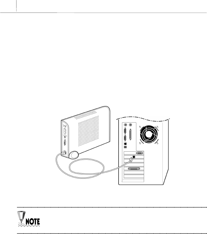
3. Connecting Ethernet Cables
Connect one side of the RJ-45 UTP Ethernet cable to the AceLink ADSL modem’s
Ethernet port (Label:10BASE-T) and connect the other side to the network adapter
installed in the PC.
Figure 2-5 Ethernet Cable Connection
In order to connect the AceLink ADSL modem to a PC, the PC must have a
10Mbps or 10/100 Mbps speed network adapter. For network adapter
installation, refer to the manual provided with the network adapter.

2-11
4. POTS Micro-filter Connection
Connect your AceLink ADSL modem to a telephone using a micro-filter by following the
procedures below.
❶Pull out the telephone line currently in use from your wall jack and connect it to the
AceLink ADSL modem’s ADSL port.
❷With the provided RJ-11 telephone cable, connect one side to the POTS micro-filter
LINE port, the other side to the AceLink ADSL modem’s Phone port.
❸
Connect RJ-11 telephone cable attached to POTS micro-filter to Y-jack port.
❹Connect RJ-11 telephone cable from Y-jack port to telephone.
❺Reverse-wire remaining Y-jack port.
Figure 2-6 POTS micro-filter connection
PHONE port
PHONE port
LINE port
ADSL port
Reverse Wiring
2-12 Chapter 2
AceLink ADSL Modem Setup
If more than two telephones are used, more POTS micro-filters are needed.
Ask your AceLink ADSL modem provider to purchase additional POTS
micro-filters.
If the telephone, used with AceLink ADSL modem, is not connected through
a POTS micro-filter, telephone conversation quality will go down.
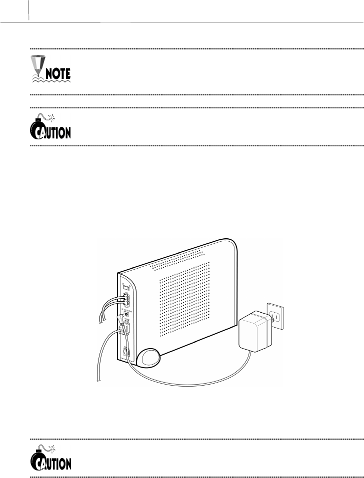
5. Power Connection
Connect power adapter to AceLink ADSL modem’s power input port (DC 5V). And then,
connect power adapter to electrical outlet.
Figure 2-7 Power adapter connection
Installation of the AceLink ADSL modem has now been completed.
The power adapter used with your ADSL modem must be the adapter
provided with your ADSL modem package.

2-13
6. Checking all the Connections
Use the following method to check all the connections.
Checking ADSL Line connection
If the ADSL Link LED blinks and then is keeping up ON within seconds of power
connection, the ADSL line is properly connected.
Checking PC connection
If network adapter’s LINK LED and AceLink ADSL modem’s User Link LED are green,
connection between PC and AceLink ADSL modem is properly established.
Checking telephone line connection
If you hear a normal signal on your telephone, and have clear reception without ghost
voices, the telephone line is properly connected.
The AceLink ADSL modem's power source does not affect the use of
telephone


A-1
Appendix A Troubleshooting
In appendix A, major problems in using the AceLink ADSL modem, and solutions
thereof will be described. Appendix A covers the following:
yPoints you must know before inquiring at the place where you purchased
yTroubleshooting - Problems and Solutions
Points You Must Know before Inquiring at the Place Where
You Purchased
When a problem, which you cannot solve, occurs during use of the system, you will
inevitably inquire at the place where you purchased it and have them assist you.
Before you inquire at the place where you purchased the system, prepare a note
including the following product information :
yProduct model name (e.g.: External AceLink ADSL Modem - Model name : SAM-
335)
yProduct serial number
yDate when product was purchased
yMemo about the problem
yMemo about what you have sequentially done to solve the problem by yourself

A-2
A
ppendix A
Troubleshooting
Troubleshooting - Problems and Solution
Many types of problems are proposed, and problems of each type that may happen are
described in detail with solutions to the problems.
Types of Problem That May Happen
The following types of problems may frequently occur when using the AceLink ADSL
modem.
yProblems related to power
yProblems related to network connection
Problems Related to Power
The following problems related to power may occur.
9Even when the power supply adapter is connected to the system and the power
supply cable connected to the power supply adapter is coupled to an electrical plug
socket, the Power LED is not lit green.
When this problem occurs, check the following :
ÂCheck that the electrical plug socket is working.
ÂRemove the jack from the power input port (DC 5V) on the back of the AceLink
ADSL modem. After about 10 seconds, connect the jack to the port again and
restart the AceLink ADSL modem.
If the problem is not solved with the above method, remove the jack from the power-
input port of AceLink ADSL modem and inquire at the place you purchased the product.

A-3
Problems Related to Network Connection
The following problems related to network connection might occur.
9The modem is not connected to the Internet.
9User Link LED or ADSL Link LED is not light.
When this problem occurs, check the following :
ÂCheck the connection state of the cables connecting the AceLink ADSL modem,
POTS micro-filter and PC.
ÂCheck the state of the network adapter installed in the PC.
ÂCheck the operating state of the PC.
ÂCheck whether an IP address is set to meet the connection service provided.
If the problem is not solved with the above method, remove the jack from the power-
input port of AceLink ADSL modem and inquire through ISP(Internet Service Provider)
or at the place you purchased the product.

B-1
Appendix B Cable Specifications
Appendix B explains the specifications of the cables connected to each port of AceLink
ADSL modem, every connector signal, and pin connection.
yEthernet Cable
yTelephone (RJ-11) Cable
Twisted pair Category-3,4,5 Straight-through Ethernet Cable
Twisted pair Category-3,4,5 Straight-through Ethernet is needed for connecting AceLink
ADSL modem to the LAN card of a PC.
Make sure to use Category-5 cable in case of connection with devices using
100Mbps Fast Ethernet.
Cable Diagram
Figure B-1 Twisted pair Category-3,4,5 Straight-through cable
B-2
A
ppendix B
Cable Specifications
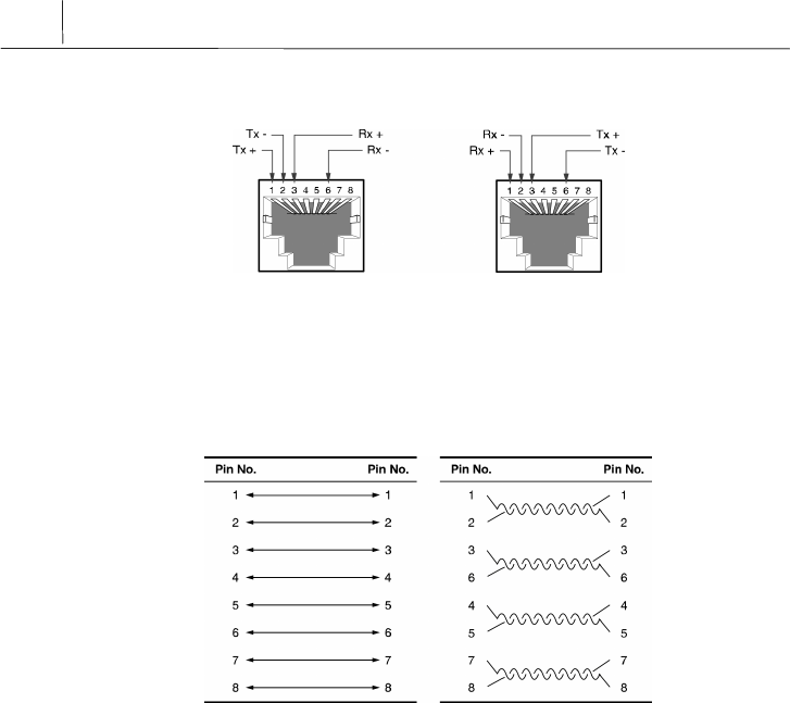
Connector Signal
ADSL Modem PC
Figure B-2 Twisted pair Category-3,4,5 Straight-through cable connector signal
Pin Connection
< Pin constitution > < Actual pin connection >
Figure B-3 Pin connection of Twisted pair Category-3,4,5 Straight-through cable connector
B-3
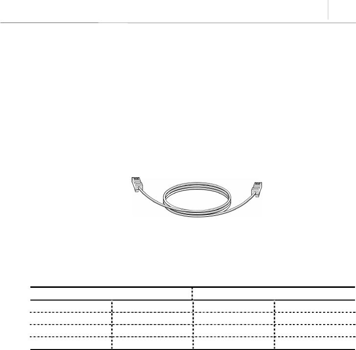
Telephone Cable (RJ-11)
We will examine the RJ-ll telephone cable connector that is used as a connector between
AceLink ADSL modem and a telephone line.
Connect one end (RJ-11 jack) of the telephone cable to the telephone port at the back of
the modem and the other end (RJ-11 jack) to the RJ-11 connector of the POTS micro-
filter.
Cable Diagram
Figure B-4 RJ-11 telephone cable
Pin Connection
RJ11 RJ11
1NC1NC
2 (A)Tip 2 (A)Tip
3 (B)Ring 3 (B)Ring
4NC4NC
Table B-1 Pin connection of RJ-11 telephone cable connector


C-1
Appendix C Description of Terms
10BASE-T
An Ethernet interface having a bandwidth, which provides a transmission rate, that may
go up to 10 Mbps using a Category 5 cable.
ATU-C (ADSL Transceiver-Central Office)
A central unit managed by an ISP(Internet Service Provider) for connection of ADSL
subscriber lines.
ATU-R (ADSL Transceiver -Remote Terminal)
A subscriber terminal which is connected to ATU-C through a telephone line, which
processes ADSL service.
ADSL (Asymmetric Digital Subscriber Line)
A device providing a high-speed data interface to the Internet, and other services,
through a telephone network. This does not influence existing telephone service. 데이
터 전송속도는 전송거리 및 ATU-C 및 서비스 종류에 따라 차이가 있으며 다운로드 속
도는 640Kbps 에서 8Mbps, 업로드 속도는 16Kbps 에서 800Kbps 입니다..
ATM (Asynchronous Transfer Mode)
One of the communications transfer modes. A control mode in which a series of
terminals can simultaneously send data while a terminal is sending data, thereby
allowing a series of terminals to share a single transmission line for communication.
Bridge
A functional unit interconnecting two or more local area networks (LANs) that uses the
same link protocol. The bridge not only transmits but also filters packets. The bridge
usually operates on a Data Link Layer when it transmits packets.
DMT (Discrete Multi-Tone)
A modulation technique of segmenting and transmitting a large amount of data by way of
Multi-carrier, in which a carrier frequency band is multiplexed, thereby realizing optimal
performance on a Loop.

C-2
A
ppendix C
Description of Terms
Ethernet
A representative method of interconnecting LANs was using a transmission cable of
10BASE standard. Three companies, i.e., Xerox, Intel and DEC develop this method, in
cooperation. Its transmission rate is about 10 Mbps, and employs a CSMA/CD access
method in which a node monitors signals over a transmission line and sends data after
confirming that the other nodes do not send signals.
Hub
A communications interface used for interconnecting a series of devices on a network.
This retransmits a signal, which is received from a device, or segments a received signal
and transmits the segmented signal.
FTP (File Transfer Protocol)
A protocol for transferring files from one host to another or from a host to a personal
computer over a network.
Gopher
An interface that has been used as the easiest interface before the WWW service was
developed. The gopher constructs a menu by classifying the contents of information by
topic or type, thereby allowing even people, whom is not familiar with the Internet, to
easily search information. In addition, other functions of the Internet such as remote
access, file transfer, news, etc. can be performed in the gopher menu. A series of gopher
servers are interconnected so that a user can search for desired information moving
from one gopher server to another.
IP (Internet Protocol) Address
An address of a host or a device on the Internet. It is composed of 4 bytes. Each byte is
divided by a period. An IP address is assigned by IANA (Internet Assigned Numbers
Authority) to avoid duplication.
PPPoA (Point-to-Point Protocol)
The standard protocol for providing the serial interface between nodes, e.g., between a
PC and a RAS or between routers, on the Internet. PPPoA provides an Internet access
rate, and is widely used substituting for a SLIP (Serial Line Internet Protocol) which is a
previously used serial interface protocol. PPPoA is designed to transmit various network
protocols including IPX. PPPoA performs various and useful functions including
negotiation of a receiving maximum packet size over a serial line.

C-3
POTS (Plane Old Telephone Service) Micro filter
A POTS micro filter separate a voice signal from a data signals not to influence an
existing telephone service. By separating PSTN using a POTS micro filter, network
service such as Internet and telephone service can be simultaneously used.
Switch
A network device for filtering and transmitting frames based on the destination address
of a frame. A switch operates at the Data Link Layer of the OSI-RM.
TCP/IP (Transmission Control Protocol/Internet Protocol)
One of the network protocols that are frequently used in a LAN. When data is
transferred through a network, data is segmented into a series of packets before
transmission. IP moves a data packet from one place to another, and TCP manages the
flow of data and checks whether data is correct.
Telnet
One of the Internets services, which is used for connecting to another computer on the
Internet. Telnet is used for remote control of a computer. When a user accesses another
computer, a user ID and a password are requested for using the computer. Telnet is used
for connecting to domestic communications on the Internet. Accordingly, a user having a
domestic communications ID can immediately connect to a domestic communications
network through ‘Telnet’.
PSTN (Public Switched Telephone Network)
A switching connection type provided by an ISP and a public communications network
premising the use by many and unspecified persons. It was originally used for the
telephone, but it is also used for communication among facsimiles and computers as
more advanced communications equipment are developed. It is also referred to as POTS.
POTS (Plain Old Telephone Service)
A telephone network which does not provide additional services.
Router
A hardware and software unit for allowing a user on one network to communicate with
another network by interconnecting two or more networks. A router transmits packets.
In addition, a router converts an address between networks at the Network Layer of
OSI-RM, and also appropriately converts a protocol.

C-4
A
ppendix C
Description of Terms
WWW (World Wide Web)
A latest multimedia service among many Internet services. Unlike Internet services
performing transmission based on letters, WWW enables photographs, graphics, voice
and motion diagrams to be transmitted and searched in a convenient hypertext format.
With the advent of this convenient and easy service, WWW enables even elementary
school students to easily access the Internet, which has been exclusively enjoyed by
only a few professionals. WWW is referred to as W3 or Web as an abbreviation.

NOTICE
y Samsung Electronics Co., Ltd. reserves the copyrights of this
book.
y This book or portions thereof may not be reproduced or
transmitted by any means, electronic, mechanical, or recording,
without the permission of the Samsung Electronics Co., Ltd.
y The content of this book may be modified due to the improvement
of functions of the product, etc.
Copyrightⓒ SAMSUNG All rights Reserved
is the registered trademark of Samsung.
AceLink ADSL modem is the registered trademark of Samsung Electronics.
The pertinent company reserves all the other registered trademarks that have been
mentioned in this book.