Samsung Electronics Co SAM335A ADSL Modem User Manual
Samsung Electronics Co Ltd ADSL Modem Users Manual
Users Manual


iii
Class B Digital Device or Peripheral
This equipment has been tested and found to comply with the limits for a
Class B digital device, pursuant to Part 15 of the FCC Rules. These limits
are designed to provide reasonable protection against harmful interference
in a residential installation. This equipment generates, uses and can radiate
radio frequency energy and, if not installed and used in accordance with the
instructions, may cause harmful interference to radio communications.
However, there is no guarantee that interference will not occur in a
particular installation. If this equipment does cause harmful interference to
radio or television reception, which can be determined by turning the
equipment off and on, the user is encouraged to try to correct the
interference by one or more of the following measures:
!Reorient or relocate the receiving antenna.
!Increase the separation between the equipment and receiver.
!Connect the equipment into an outlet on a circuit different from that to
which the receiver is connected.
!Consult the dealer or experienced radio TV technician for help.

iv
Changes or modifications not expressly approved by the
manufacturer responsible for compliance could void the user's
authority to operate the equipment.
Copyright © Samsung Electronics Co. Ltd. And Samsung Telecommunications America, Inc. 2001
All rights reserved. Samsung, the Samsung logo, Samsung AceLink are
registered trademarks. All other product names are used for identification
only and may be trademarks and/or registered trademarks of their
respective companies. Product specifications subject to change without
notice.
No part of this publication may be reproduced in any form or by any means
or used to make any derivatives such as translation, transformation, or
adaptation without permission from Samsung Electronics as stipulated by
the United States Copyright Act of 1976.

v
Limited Warranty
1. What Is Covered And For How Long ? SAMSUNG TELECOMMUNICATIONS AMERICA,
INC.(“SAMSUNG”)warrants to the original purchaser that SAMSUNG’s ADSL Modems are free from defects in
material and workmanship under normal use and service for the period commencing upon the date of purchase
and continuing for the following specified period of time after that date :
AceLinkTM ADSL Modem 2 years
2. What is not covered? This Limited Warranty is conditional upon proper use of the product by the purchaser.
The Limited Warranty does not cover : (a) defects or damage resulting from accident, misuse, abuse, neglect,
unusual physical, electrical or electromechanical stress, modification of any part of the product, or cosmetic
damage; (b) equipment that has the serial number removed or made illegible;(c) all plastic surfaces and other
externally exposed parts that are scratched or damaged due to normal use;(d) malfunctions resulting from the
use of the product in conjunction with accessories, products or ancillary or peripheral equipment not authorized
and approval of by SAMSUNG; (e) defects or damage from improper testing, operation, maintenance, installation,
or adjustment. Please call SAMSUNG’s customer care center at 1-888-987-4357 for updated pricing on non-
warranty repairs.
3. What Are SAMSUNG’s Obligations? During the applicable warranty period, SAMSUNG will repair or replace,
at SAMSUNG’s sole option, without charge to purchaser, any defective component part of the ADSL Modem or
accessory. To obtain service under this Limited Warranty, purchaser must return the product to an authorized
SAMSUNG service facility in an adequate container for shipping, accompanied by purchaser’s sales receipt or
comparable substitute proof of purchase showing the date of purchase, the serial number of the product, and the
sellers name and address. To obtain assistance on where to deliver the ADSL Modem, call SAMSUNG customer
care at 1-888-987-4357. Upon receipt, SAMSUNG will promptly repair or replace the defective product.
SAMSUNG may, at SAMSUNG’s sole option, use rebuilt, reconditioned, or new parts or components when
repairing any product or replace a product with a rebuilt, reconditioned or new product. Repaired products will be
warranted for a period equal to the remainder of the original Limited Warranty on the original product or for 90
days, which ever is longer. All replaced parts, components, boards and equipment shall become the property of
SAMSUNG. If SAMSUNG determines that the product is not covered by this Limited Warranty or that the
product is not defective, the purchaser must pay all parts, shipping, and labor charge for the testing, repair and
return of the product.
4. What Are The Limits On SAMSUNG’s Liability? THE WARRANTIES GIVEN IN THIS WARRANTY ARE
LIMITED TO THE DURATION OF THIS LIMITED WARRANTY SET OUT ABOVE. EXCECT TO THE
EXTENT PROHIBITED BY APPLICABLE LAW, SAMSUNG SHALL NOT BE LIABLE FOR ANY SPECIAL,
INCIDENTAL, CONSEQUENTIAL, INDIRECT OR SIMILAR DAMAGES, LOSS OF PROFITS, DAMAGES
TO PURCHASER PROPERTY, OR INJURY TO PURCHASER OR OTHERS ARISING OUT OF THE USE,
MISUSE OR INABILITY TO USE ANY SAMSUNG ADSL MODEM, BREACH OF WARRANTY, BREACH OF
CONTRACT, OR NEGLIGENCE, INCLUDING BUT NOT LIMITED TO SAMSUNG’S OWN NEGLIGENCE,
EVEN IF SAMSUNG OR ITS AGENT HAS BEEN ADVISED OF SUCH DAMAGES, OR FOR ANY CLAIM
BROUGHT AGAINST PURCHASER BY ANY OTHER PARTY.

vi
THIS LIMITED WARRANTY IS THE COMPLETE WARRANTY FOR SAMSUNG’S ADSL MODEM, AND
SAMSUNG HEREBY DISCLAIMS ANY OTHER WARRANTIES, EXPRESS OR IMPLIED, IMCLUDING ANY
IMPLIED WARRANTY OF MERCHANTABILITY OR FITNESS FOR A PARTICULAR PURPOSE. THIS
LIMITED WARRANTY SHALL NOT EXTEND TO ANYONE OTHER THAN THE ORIGINAL PURCHASER
OF THIS PRODUCT AND STATES PURCHASER’S EXCLUSIVE REMEDY. IF ANY PORTION OF THIS
WARRANTY IS ILLEGAL OR UNENFORCEABLE BY REASON OF ANY LAY, SUCH PARTIAL ILLEGALITY
OR UNENFORCEABILITY SHALL NOT AFFECT THE ENFORCEABILITY OF THE REMAINDER OF THIS
LIMITED WARRANTY WHICH PURCHASER ACKNOWLEDGES IS AND ALWAYS WILL BE
CONSTRUCTED TO BE LIMITED BY ITS TERMS OR AS LIMITED AS THE LAW PERMITS.
The Limited Warranty allocates the risk of product failure between purchaser and SAMSUNG, and SAMSUNG’s
product pricing reflects this allocation of risk and the limitations of liability contained in this Limited Warranty.
The agents, employees, distributors, and dealers of SAMSUNG are not authorized to make modifications to this
Limited Warranty, or make additional warranties binding on SAMSUNG. Accordingly, additional statements such
as dealer advertising or presentation, whether oral or written, do not constitute warranties by SAMSUNG and
should not be relied upon. 5.
5. How Does State Law Apply To This Warranty? SOME STATES DO NOT ALLOW THE EXCLUSION OR
LIMITATIONS OF INCIDENTAL OR CONSEQUENTIAL DAMAGES OR HOW LONG AN IMPLIED
WARRANTY LASTS, SO THE ABOVE LIMITATIONS OR EXCLUSIONS MAY NOT APPLY TO YOU IN
THEIR ENTIRETY.
The Limited Warranty gives you specific legal rights. You may also have other rights that vary
from one jurisdiction to another.
SAMSUNG Telecommunications America, Inc.
1601 East Plano Parkway Suite 150
Plano, TX 75074
Tel : 1-888-987-HELP(4357)
Fax : 1-972-761-7501
The software provided with this product is not covered under the hardware warranty described above. See
Minimum End-User Software License Terms which was shipped with the product for details on the software
warranty.

vii
Intellectual Property
All Intellectual Property, as defined below, owned by or which is otherwise
the property of Samsung or its suppliers relating to the AceLink™,
including but not limited to, accessories, parts or software relating thereto
(the ADSL Modem System), is proprietary to federal laws and state laws,
and international treaty provisions. Intellectual Property includes, but is
not limited to, inventions (patentable or unpatentable), patents, trade
secrets, copyrights, software, computer programs, and related
documentation and other works of authorship.
You may not infringe or otherwise violate the rights secured by the
Intellectual Property. Moreover, you agree you will not (and will not
attempt to) modify, prepare derivative works of, reverse engineer,
decompile, disassemble, or otherwise attempt to create source code from
the software.
No title to or ownership in the Intellectual Property is transferred to you.
All applicable rights of the Intellectual Property shall remain with Samsung
and its suppliers.
© 2001 Samsung Electronics Co., LTD. All rights reserved. No
reproduction in whole or in part allowed prior written approval.

viii
Before Starting
This manual is for AceLink ADSL modem users. This book includes from
the introduction to installation, and problem solutions.
We recommend that the user read this guide carefully before operation of
equipment.
If already familiar with the ADSL modem or similar systems, please read
the notices in the explanations for review.
If you encounter any problems or have any questions, please contact the
service provider.

ix
About Manual
Following contents are described in each chapter of AceLink ADSL modem
manual.
Chapter 1 ‘Introduction’ describes the main functions of the AceLink
ADSL modem, as well as its applications, hardware structure,
and specifications
Chapter 2 ‘AceLink ADSL Modem Setup’ examines what the user
must know before installation, and describes the AceLink
ADSL modem setting environment and installation.
Appendix A ‘Troubleshooting’ describes major problems in using the
AceLink ADSL modem, and solutions.
Appendix B ‘Cable Specifications’ describes every sort of cable
specification that is needed for installation of AceLink ADSL
modem.
Appendix C ‘Description of Terms’ explains terminology that you need
to know during the use of AceLink ADSL modem.

x
Contents(수정)
Chapter 1 Introduction ................................. 1-1~1-8
Introduction to AceLink ADSL modem ............................1-2
Name and Function of each part.......................................1-3
Front View...........................................................................1-3
Rear View............................................................................1-4
AceLink ADSL modem specifications...............................1-5
Hardware Features..............................................................1-5
Software Specifications
.........................................................1-8
Chapter 2 AceLink ADSL Modem Setup....... 2-1~2-16
Before Installation .............................................................2-2
Safety Check.......................................................................2-2
Service Environment Check..............................................2-3
Preparing cables..................................................................2-4
Modem Setting Environment.............................................2-6
Checking the Contents.......................................................2-7
Modem Setup .....................................................................2-8
1. Drawing the Network Configuration..............................2-9
2. Assembling the supporter............................................2-10
3. Power Disconnection....................................................2-12
4. Connecting Ethernet Cables........................................2-12
5. POTS Micro-filter Connection.....................................2-14
6. Power Connection.........................................................2-16
7. Checking all the Connections.......................................2-17
Appendix A Troubleshooting.......................A-1~A-3
Points You Must Know before Inquiring at the Place
Where You Purchased ..................................................... A-1
Troubleshooting - Problems and Solution ........................ A-2
Appendix B Cable Specifications.................. B-1~B-3
Twisted pair Category-3,4,5 Straight-through
Ethernet Cable.................................................................B-1
Telephone Cable (RJ-11)....................................................B-3
Appendix C Description of Terms.................C-1~C-5

xi
Figure Contents(수정)
Figure 1-1 Front view of AceLink ADSL modem......................................1-3
Figure 1-2 Rear view of AceLink ADSL modem........................................1-4
Figure 2-1 RJ-11 telephone cable................................................................2-4
Figure 2-2 RJ-45 UTP Ethernet Cable .......................................................2-5
Figure 2-3 AceLink modem package ..........................................................2-7
Figure 2-4 Example of network configuration............................................2-9
Figure 2-5 Fixing the protrusion on the front to the groove of the
stand holder.............................................................................2-10
Figure 2-6 Press the stand holer to the AceLink ADSL modem.............2-10
Figure 2-7 AceLink ADSL modem with stand holder..............................2-11
Figure 2-8 Ethernet Cable Connection.....................................................2-12
Figure 2-9 POTS micro-filter connection.................................................2-14
Figure 2-10 Power adapter connection.....................................................2-16
Figure B-1 Twisted pair Category-3,4,5 Straight-through cable.............. B-1
Figure B-2 Twisted pair Category-3,4,5 Straight-through cable
connector signal.......................................................................B-2
Figure B-3 Pin connection of Twisted pair Category-3,4,5
Straight-through cable connector............................................ B-2
Figure B-4 RJ-11 telephone cable.............................................................. B-3

xii
Table Contents(수정)
Table 1-1 AceLink ADSL modem's LED functions....................................1-3
Table 1-2 AceLink ADSL modem's port functions.....................................1-4
Table 1-3 Hardware specifications of AceLink ADSL modem...................1-5
Table 1-4 DMT specifications of AceLink ADSL modem..........................1-6
Table 1-5 Specifications of external connector of
AceLink ADSL modem...............................................................1-7
Table 1-6 Specifications of external connector of
AceLink ADSL modem...............................................................1-7
Table 1-7 Specifications of AceLink ADSL modem software....................1-8
Table 2-1 Cables used by AceLink ADSL modem .....................................2-4
Table B-1 Pin connection of RJ-11 telephone cable connector................. B-3


1-1
Chapter 1 Introduction
This chapter describes the main functions of the AceLink ADSL modem,
as well as its applications, hardware structure, and specifications.
!Introduction to the AceLink ADSL modem
!Name and function of each component
!AceLink ADSL modem specifications

1-2 Chapter 1
Introduction
Introduction to AceLink ADSL modem
It is possible to access the Internet and other multimedia service networks
through an existing telephone line (PSTN) using AceLink ADSL modem.
Unlike previous dial-up modems, AceLink ADSL modems provide the
fastest speed available as well as allow use of the telephone at the same
time.
Characteristics of AceLink ADSL modem;
Various Applications
Some of the applications of AceLink ADSL modem include Internet access,
chatting (real-time communication), file transfers, and data
download/upload.
Inexpensive Price
AceLink ADSL modem uses a pre-existing phone line (PSTN) instead of
using a separate cable, which needs a great amount of money and time to
install.
Reliable Network Connection
AceLink ADSL modem operates in connection with the master system in
the local telephone office letting the telephone office manage all of the
networking services.
Easy Installation
AceLink ADSL modem is easy install so that a popular user can easily
connect to ISP(Internet Service Provider) and receive the internet service.
Web-based Management
AceLink ADSL modem provides a web environment management function.
Whereby, the user can monitor the modem’s state and change the settings
easily.
1-3
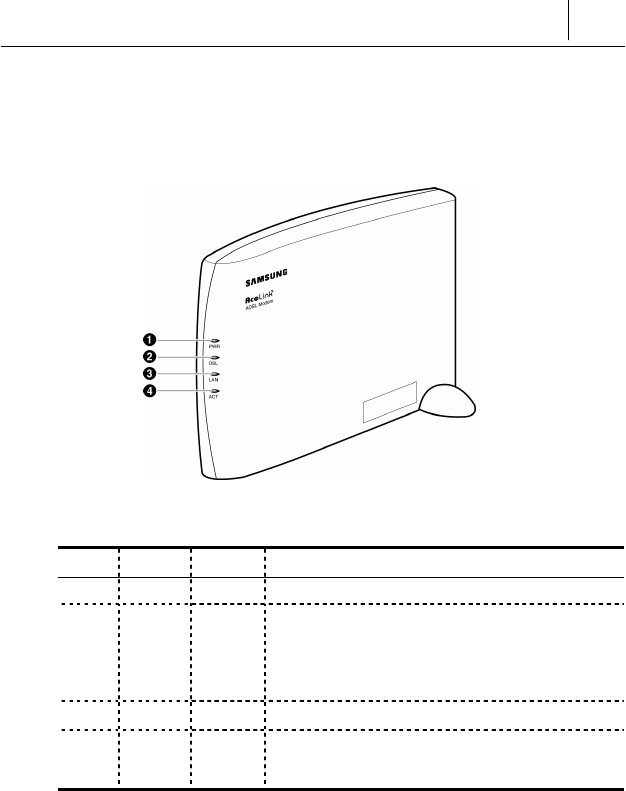
Name and Function of each part
Front View
Figure 1-1 Front view of AceLink ADSL modem
Numbe
r
Label Color Function
❶PWR Green On, while AC power is provided.
❷DSL Green
This LED turns on while connecting with
ADSL main system of telephone office and
blinks with amber color while sending or
receiving data with CO.
❸LAN Green On, while connected to PC.
❹ACT Green Flashing, when sending/receiving data through
PC.
Table 1-1 AceLink ADSL modem's LED functions
1-4 Chapter 1
Introduction
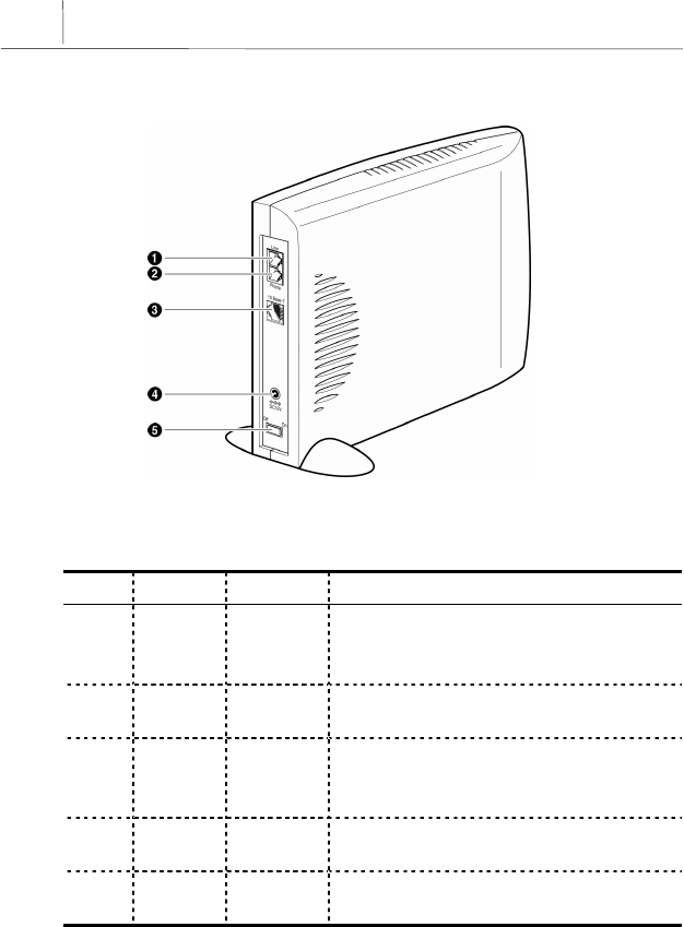
Rear View
Figure 1-2 Rear view of AceLink ADSL modem
Number Label Port Function
❶Line ADSL line
port
Connect RJ-11 telephone line from the
telephone socket on the wall. This port is
used to send/receive ADSL data.
❷Phone Telephone
port Connected to ordinary telephone through
micro-filter.
❸10Base-T Ethernet
port
Connect to PC’s network adapter by using
UTP. Category-3,4,5 Straight-through cable.
Provide up to 10Mbps speed.
❹DC 5V Power
input port A jack to connect Input power (AC 110V, DC
5V adapter) to ADSL modem.
❺On / Off Power
Switch A power switch of AceLink ADSL Modem.
Table 1-2 AceLink ADSL modem's port functions

1-5
AceLink ADSL modem specifications
Hardware Features
Category Specification
Power Supply
of Main Board
! Input Power : DC 5V (5V/1.5A)
! Voltage usable : 3.3V and 12V
! Power consumed : 4.5Watts (Max)
Power Supply
Adapter
! Rated Input : AC 110V, 60Hz
! Rated Output : DC +5.0V 1.5A
User Interface
! ADSL Interface(RJ-11) : ADSL Line
! Telephone Interface(RJ-11) : Telephone Line
! Ethernet Interface(RJ-45) : Connection to 10Mbps
Ethernet Port (Straight-through)
LED
! PWR : A green light is on during normal operation of
the modem.
! DSL : On, while connected to telephone office’s ADSL
master system.
! LAN : A green light is on when it is linked to Ethernet
port of PC.
! ACT : A green light is on during transmitting/receiving
of data with PC.
Package
! Package Material : Plastic
! Dimension : 38(width) x 178(length) x 153(height) mm
! Weight : 1 Kg (modem, power supply device and cables
are included)
! Installation : Vertical installation is available (an
installation rack is provided).
Table 1-3 Hardware specifications of AceLink ADSL modem
1-6 Chapter 1
Introduction
DMT Specifications
Category Down Stream Up stream Remarks
Max Data
Rate 8Mbps 800Kbps
AeLink ADSL
modem's speed can
vary depending on
length and
characterics of the
line between
DSLAM and
modem.
ADSL
OverHead 96Kbps 32Kbps Frame Mode 3
Bandwidth 0.11Mhz ~ 1.1Mhz 30Khz ~ 110Khz
TX Power 20dBm 12dBm
Bin Width 4.3125Khz T1.413 standard
(+/-50ppm)
Max Sym/bin 16 Bit
Latency Fast channel : < 2ms, Interleaved <
20ms
Applied
Standard ANSI/T1.413, ITU-T/G.992.1, ITU-
T/G.992.2
Table 1-4 DMT specifications of AceLink ADSL modem
1-7
External Connector Specifications
Type Options Remarks
RJ-45 Ethernet ! Internet access available by
connecting to external PC
RJ-11 ADSL Line ! Connected to external ADSL line
RJ-11 Telephone
Line
! Telephone access available through
external micro-filter
Power Jack ! AC/DC converter 5V adapter
Power Switch ! Power On/Off switch
Table 1-5 Specifications of external connector of AceLink ADSL modem
Other Specifications
Content Item Remarks
Working Temp. 0 ~ 45℃
Telephone
Service Linked to telephone using external
micro-filter
Foreign Standard Form approval(EMI CLASS B)
U.S. FCC Part 15 & 68
Table 1-6 Specifications of external connector of AceLink ADSL modem
1-8 Chapter 1
Introduction
Software Specifications
Category Specification Remarks
Access Mode ! PPPoE mode
(RFC 1516-PPP Over Ethernet)
Management
Function
! CLI (Command Line Interpreter)
! Telnet
! SNMP agent
! Setup of web environment
! Software upgrade
! Traffic statistics monitoring
Table 1-7 Specifications of AceLink ADSL modem software
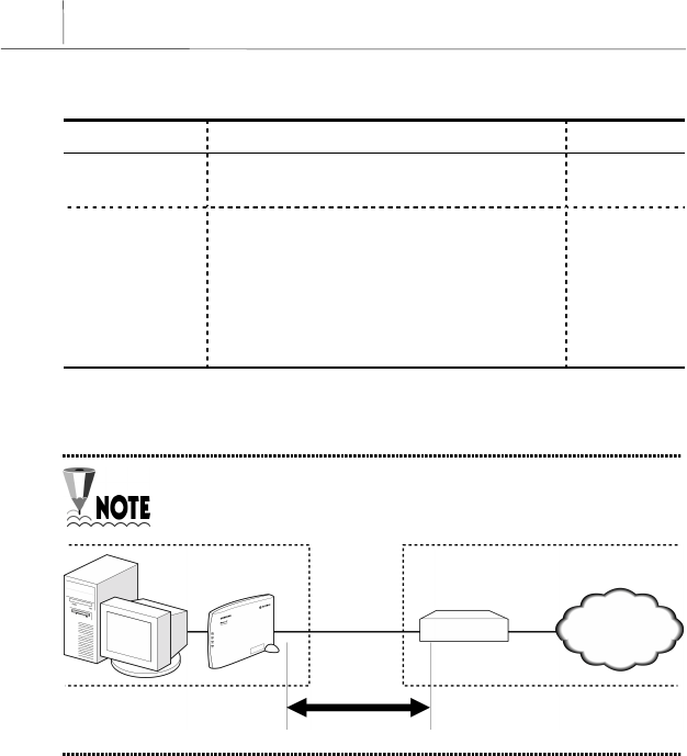
AceLink ADSL modem's speed can vary depending on length
and characterics of the line between DSLAM and modem.
Home Telephone Office
PC ADSL Modem
DSLAM
Modem-DSLAM
Internet


2-1
Chapter 2 AceLink ADSL Modem Setup
This chapter introduces the environment where AceLink ADSL modem
can be installed and explains how to install this product and link it to a
network.
This chapter consists of the following contents.
!Before installation
!Checking the Contents
!Modem Setup

2-2 Chapter 2
AceLink ADSL Modem Setup
Before Installation
This chapter examines what the user must know before installation.
Before installation of your ADSL modem follow the directions described in
this chapter.
Safety Check
Before proceeding with the installation of the AceLink ADSL modem, user
must check the following categories.
Electricity Safety check
!The user should not remove or open the product’s cover, it is especially
dangerous when the power is on.
!Check and make sure if there are any flammable, electric conducting
objects around the modem. Make sure that there are no wet objects
around. And check if the cable is not worn out and other electrical
devices around the modem are properly grounded.
Location check
!Electrical products tend to generate heat during operation. It is possible
that if the environment does not provide enough ventilation it would
result in improper function of the modem. Make sure that the modem is
exposed to circulating air.
!Check if the power is properly provided. If it happens to cause sparks or
noise, be sure to install a voltage regulator.

2-3
Service Environment Check
Check the followings before installing your AceLink ADSL modem.
Telephone network service
The AceLink ADSL modem should be installed where telephone
network service is available.
If there is no telephone line available in your area, be sure to report to the
local telephone office to construct a telephone line.
The telephone network service must support ADSL modem
connection.
Some of the telephone network services will support ADSL applications.
Check with your local telephone office for subscription of ADSL.
PC Specification Check
In order to use AceLink ADSL modem by connecting to a PC, a LAN card
(10Base-T or 10/100Base-T network adapter) must be installed in your PC.
You can purchase the LAN card at any PC shop.
2-4 Chapter 2
AceLink ADSL Modem Setup
Preparing cables
You must have all cables ready before connecting to the network. The
following cables are needed to connect the AceLink ADSL modem to the
network.
Port Required cable
ADSL/Telephone line port
(Line, Phone) RJ-11 cables.
Ethernet port (10BASE-T) RJ-45 UTP Category-3,4,5 Straight-
through cable.
Table 2-1 Cables used by AceLink ADSL modem
More detailed specification of each cable is described in
Appendix C "Cable Specifications".
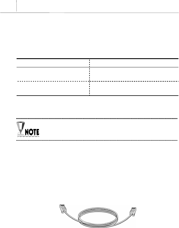
RJ-11 cable
One end of the RJ-11 cable is connected to telephone line port (Phone) in
the back of the AceLink ADSL modem, and the other is connected to the
POTS micro-filter (LINE) which is provided separately. The specification of
RJ-11 cable should be 26AWG or higher.
Figure 2-1 RJ-11 telephone cable
2-5
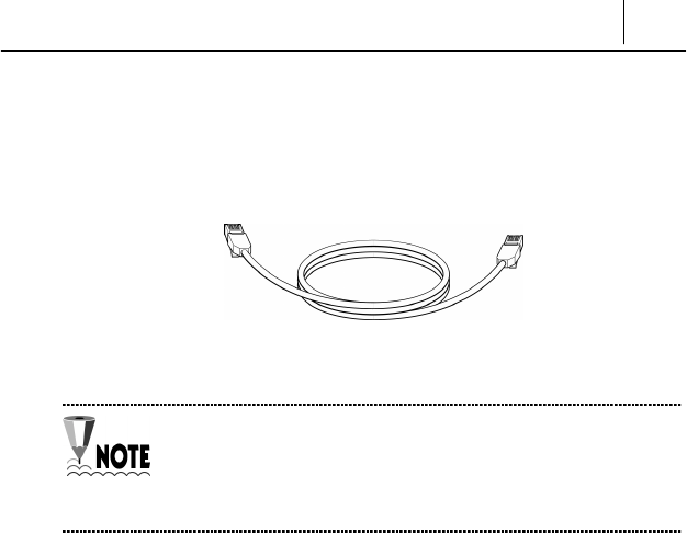
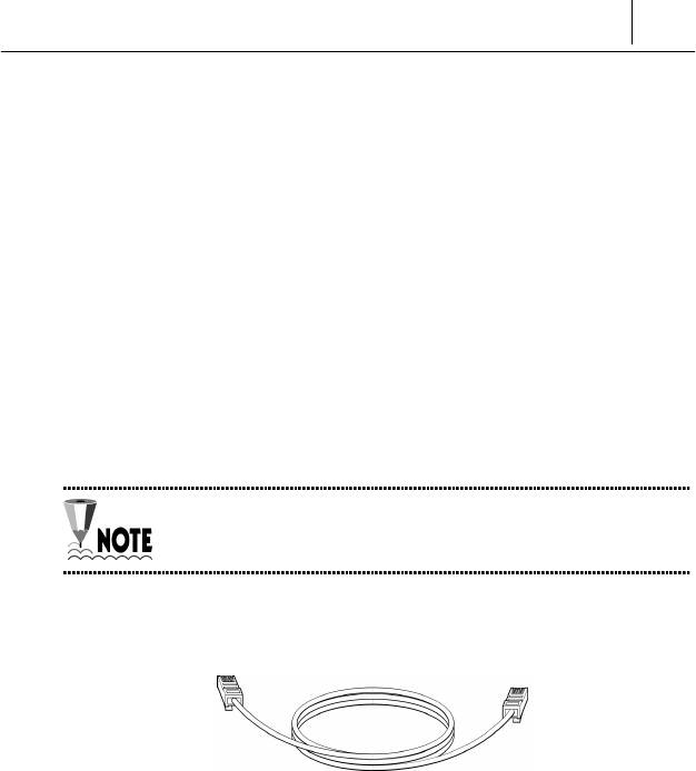
RJ-45 UTP Ethernet cable
Connect one end of the RJ-45 UTP Ethernet cable to the Ethernet port
(10BASE-T) which is at the rear plane of AceLink ADSL modem and
connect the other end to the LAN card of the PC.
Figure 2-2 RJ-45 UTP Ethernet Cable
Cables may look alike, however they could be different, for
example they could have different inner pins. Therefore, in
order not to use them with other cables, it is recommended to
label each cable.
2-6 Chapter 2
AceLink ADSL Modem Setup
Modem Setting Environment
For safe installation, let’s examine the AceLink ADSL modem setting
environment.
The AceLink ADSL modem should be kept at moderate temperature and
humidity.
The recommended environment is as follows:
! Temperature : 0 ~ 45℃
! Relative humidity : 10 ~ 90% (uncondensed)
! Power : 4.5 Watts (maximum)
! Input power : AC 110V, DC 5V
! Frequency : 60Hz
The voltage variation of the power input during operation
should be within 5% of regulatory voltage. The electrical outlet
should be grounded. Also, the AceLink ADSL modem's power
connecter should not be used on the same outlet where a hair
dryer, iron or refrigerator is connected. To provide a stable
power supply, an AVR (Automatic Voltage Regulator) is
recommended to be used.
2-7
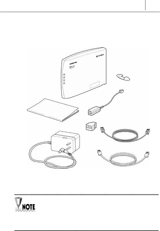
Checking the Contents
After purchasing your AceLink ADSL modem package, open the box and
check if all the following contents are included.
Figure 2-3 AceLink modem package
A POTS micro-filter is needed to use the ordinary telephone
service and ADSL data service at the same time. You need to
prepare a POTS micro-filter for each telephone used in your
home. Ask your AceLink ADSL modem provider about
purchasing additional POTS micro-filters.
A
ceLink ADSL Modem
POTS Micro-filter
User Guide
RJ-11 Telephone Cable
Y Jack
RJ-45 UTP Ethernet Cable
Power Adapter

2-8 Chapter 2
AceLink ADSL Modem Setup
Modem Setup
We will go over how to configure your AceLink ADSL modem.
Configuration procedures are as follows :
1. Drawing the network configuration
2. Assembling the supporter
3. Power disconnection
4. Ethernet Cable connection
5. POTS micro-filter connection
6. Power connection
7. Checking all the connections
Each step is described in detail below.
2-9
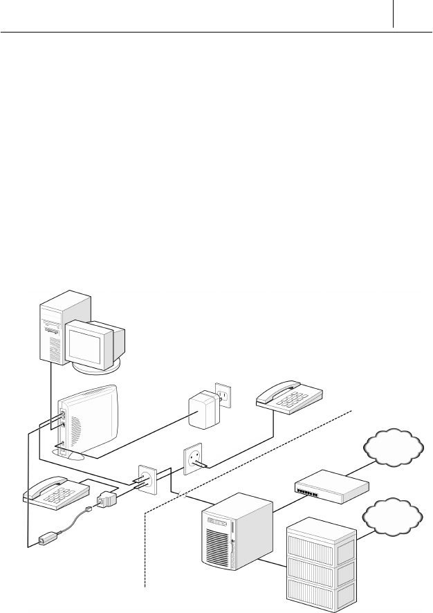
1. Drawing the Network Configuration
First, it is better to draw a network configuration for the AceLink ADSL
modem. You must consider the following matters when drawing a network
configuration.
!What will the AceLink ADSL modem are used for?
!Are you going to use the AceLink ADSL modem and telephone at the
same time?
!Have you prepared all the necessary equipment such as PC, POTS
micro-filter, telephone, and network cable?
The diagram below is an example configuration of an AceLink modem to
PC, POTS micro-filter and telephone. Draw your own configuration in
reference with this diagram.
Figure 2-4 Example of network configuration
Internet
PSTN
PC
Telephone #2
POTS Micro-filter #1
Route
r
LINE
LINE
10Base-T
A
DSL modem
Telephone #1
Switch System
AceLink ADSL system
(DSLAM)
Subscriber's home telephone network
AC 110V
2-10 Chapter 2
AceLink ADSL Modem Setup
Fix the narrow grooves into the
protrusion on the backside first.
Protrusion on the back
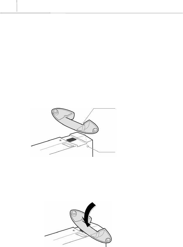
2. Assembling the supporter
Locate AceLink ADSL modem in a flat surface away from direct sunlight. It
is also necessary to put AceLink ADSL modem in a place close to the cable
outlet or cable splitter for easier connection of cables. Then fix the stand
holder into the AceLink ADSL modem as following:
❶There is a small protrusion at the lower right part on the front side (on
which SAMSUNG logo is printed) of the AceLink ADSL modem. Also,
there is another one at the lower left part on the backside of the
AceLink ADSL modem. First, fix the protrusion on the backside of the
AceLink ADSL modem into the narrow groove of the stand holder.
Figure 2-5 Fixing the protrusion on the front to the groove of the stand holder
❷Next, adjust the middle of the stand holder to the hollow part under the
AceLink ADSL modem. Then, press the middle of the stand holder.
Figure 2-6 Press the stand holer to the AceLink ADSL modem
Press the middle of the stand holder.
2-11
❸The AceLink ADSL modem with stand holder is described below.
Be sure to fix the stand holder into the AceLink ADSL modem
with the proper attention. Failure to fix the stand holder into
the AceLink ADSL modem accurately as is described in this
chapter can break the stand holder.
Figure 2-7 AceLink ADSL modem with stand holder
2-12 Chapter 2
AceLink ADSL Modem Setup
3. Power Disconnection
If power is supplied to the AceLink ADSL modem, be sure to pull out the
power cord from the electrical outlet before connecting the modem to any
other device.
4. RJ-11 Cable Connection
If power is supplied to the AceLink ADSL modem, be sure to pull out the
power cord from the electrical outlet before connecting the modem to any
other device.
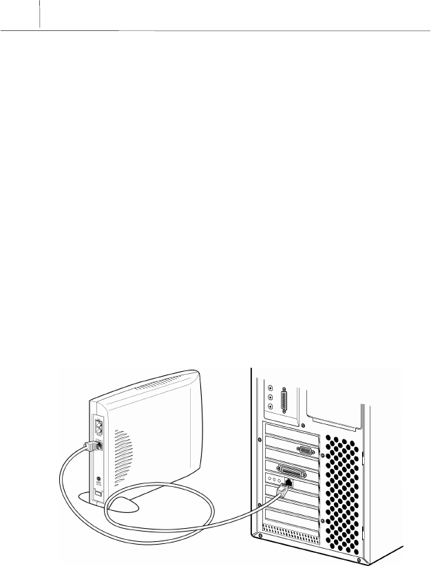
4. Connecting Ethernet Cables
Connect one side of the RJ-45 UTP Ethernet cable to the AceLink ADSL
modem’s Ethernet port (Label:10Base-T) and connect the other side to the
network adapter installed in the PC.
Figure 2-8 Ethernet Cable Connection

2-13
In order to connect the AceLink ADSL modem to a PC, the PC
must have a 10Mbps or 10/100 Mbps speed network
adapter. For network adapter installation, refer to the manual
provided with the network adapter.
2-14 Chapter 2
AceLink ADSL Modem Setup
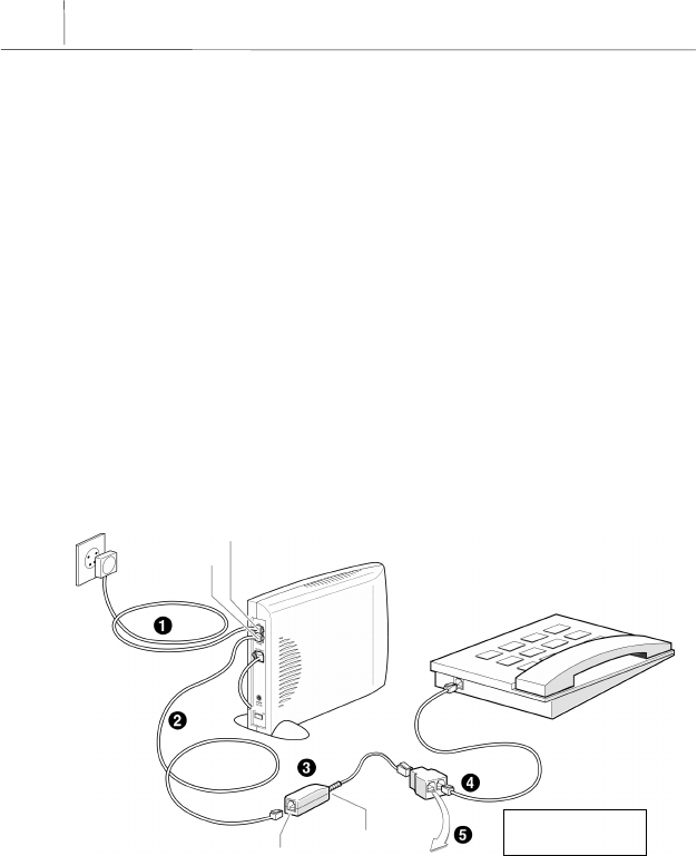
5. POTS Micro-filter Connection
Connect your AceLink ADSL modem to a telephone using a micro-filter by
following the procedures below.
❶Pull out the telephone line currently in use from your wall jack and
connect it to the AceLink ADSL modem’s Line port.
❷With the provided RJ-11 telephone cable, connect one side to the POTS
micro-filter LINE port, the other side to the AceLink ADSL modem’s
Phone port.
❸Connect RJ-11 telephone cable attached to POTS micro-filter to Y-jack
port.
❹Connect RJ-11 telephone cable from Y-jack port to telephone.
❺Reverse-wire remaining Y-jack port.
Figure 2-9 POTS micro-filter connection
Line port
PHONE port
LINE port
Phone port
Reverse Wiring
2-15
If more than two telephones are used, more POTS micro-
filters are needed. Ask your AceLink ADSL modem provider to
purchase additional POTS micro-filters.
If the telephone, used with AceLink ADSL modem, is not
connected through a POTS micro-filter, telephone
conversation quality will go down.
2-16 Chapter 2
AceLink ADSL Modem Setup
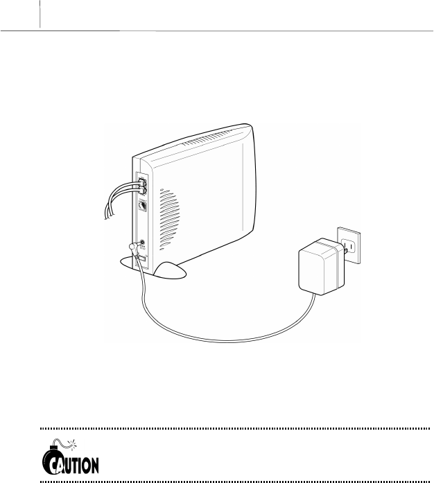
6. Power Connection
Connect power adapter to AceLink ADSL modem’s power input port (DC
5V). And then, connect power adapter to electrical outlet.
Figure 2-10 Power adapter connection
Installation of the AceLink ADSL modem has now been completed.
The power adapter used with your ADSL modem must be the
adapter provided with your ADSL modem package.
2-17
7. Checking all the Connections
Use the following method to check all the connections.
Checking ADSL Line connection
If the Line LED blinks and then is keeping up ON within seconds of power
connection, the ADSL line is properly connected.
Checking PC connection
If network adapter’s Link LED and AceLink ADSL modem’s LAN LED are
green, connection between PC and AceLink ADSL modem is properly
established.
Checking telephone line connection
If you hear a normal signal on your telephone, and have clear reception
without ghost voices, the telephone line is properly connected.
The AceLink ADSL modem's power source does not affect the
use of telephone.


A-1
Appendix A Troubleshooting
In appendix A, major problems in using the AceLink ADSL modem, and
solutions thereof will be described. Appendix A covers the following:
!Points you must know before inquiring at the place where you
purchased
!Troubleshooting - Problems and Solutions
Points You Must Know before Inquiring at the
Place Where You Purchased
When a problem, which you cannot solve, occurs during use of the system,
you will inevitably inquire at the place where you purchased it and have
them assist you.
Before you inquire at the place where you purchased the system, prepare a
note including the following product information :
!Product model name (e.g.: External AceLink ADSL Modem - Model
name : SAM-335A)
!Product serial number
!Date when product was purchased
!Memo about the problem
!Memo about what you have sequentially done to solve the problem by
yourself

A-2
A
ppendix A
Troubleshooting
Troubleshooting - Problems and Solution
Many types of problems are proposed, and problems of each type that may
happen are described in detail with solutions to the problems.
Types of Problem That May Happen
The following types of problems may frequently occur when using the
AceLink ADSL modem.
!Problems related to power
!Problems related to network connection
Problems Related to Power
The following problems related to power may occur.
"Even when the power supply adapter is connected to the system and
the power supply cable connected to the power supply adapter is
coupled to an electrical plug socket, the PWR LED is not lit green.
When this problem occurs, check the following :
#Check that the electrical plug socket is working.
#Remove the jack from the power input port (DC 5V) on the back of
the AceLink ADSL modem. After about 10 seconds, connect the jack
to the port again and restart the AceLink ADSL modem.
If the problem is not solved with the above method, remove the jack from
the power-input port of AceLink ADSL modem and inquire at the place you
purchased the product.

A-3
Problems Related to Network Connection
The following problems related to network connection might occur.
"The modem is not connected to the Internet.
"LAN LED or ACT LED is not light.
When this problem occurs, check the following :
#Check the connection state of the cables connecting the AceLink
ADSL modem, POTS micro-filter and PC.
#Check the state of the network adapter installed in the PC.
#Check the operating state of the PC.
#Check whether an IP address is set to meet the connection service
provided.
If the problem is not solved with the above method, remove the jack from
the power-input port of AceLink ADSL modem and inquire through
ISP(Internet Service Provider) or at the place you purchased the product.

B-1
Appendix B Cable Specifications
Appendix B explains the specifications of the cables connected to each port
of AceLink ADSL modem, every connector signal, and pin connection.
!Ethernet Cable
!Telephone (RJ-11) Cable
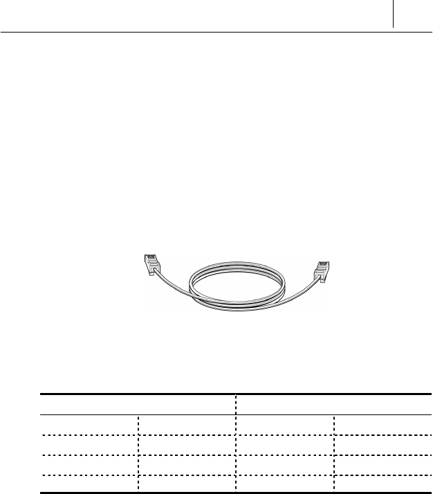
Twisted pair Category-3,4,5 Straight-through Ethernet Cable
Twisted pair Category-3,4,5 Straight-through Ethernet is needed for
connecting AceLink ADSL modem to the LAN card of a PC.
Make sure to use Category-5 cable in case of connection with
devices using 100Mbps Fast Ethernet.
Cable Diagram
Figure B-1 Twisted pair Category-3,4,5 Straight-through cable
B-2
A
ppendix B
Cable Specifications
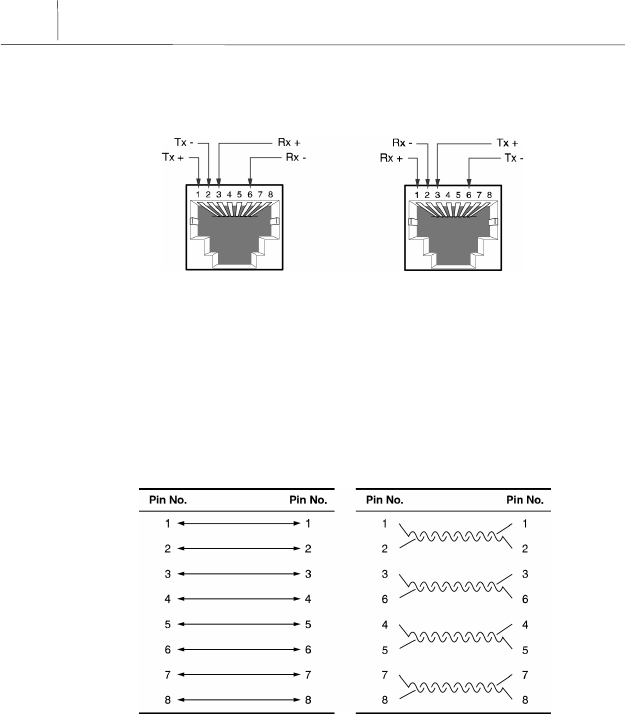
Connector Signal
ADSL Modem PC
Figure B-2 Twisted pair Category-3,4,5 Straight-through cable connector signal
Pin Connection
< Pin constitution > < Actual pin connection >
Figure B-3 Pin connection of Twisted pair Category-3,4,5 Straight-through cable connector
B-3
Telephone Cable (RJ-11)
We will examine the RJ-ll telephone cable connector that is used as a
connector between AceLink ADSL modem and a telephone line. The
specification of RJ-11 cable should be 26AWG or higher.
Connect one end (RJ-11 jack) of the telephone cable to the telephone port
at the back of the modem and the other end (RJ-11 jack) to the RJ-11
connector of the POTS micro-filter.
Cable Diagram
Figure B-4 RJ-11 telephone cable
Pin Connection
RJ-11 RJ-11
1NC1NC
2 (A)Tip 2 (A)Tip
3 (B)Ring 3 (B)Ring
4NC4NC
Table B-1 Pin connection of RJ-11 telephone cable connector


C-1
Appendix C Description of Terms
10BASE-T
An Ethernet interface having a bandwidth, which provides a transmission
rate, that may go up to 10 Mbps using a Category 5 cable.
ATU-C (ADSL Transceiver-Central Office)
A central unit managed by an ISP(Internet Service Provider) for
connection of ADSL subscriber lines.
ATU-R (ADSL Transceiver -Remote Terminal)
A subscriber terminal which is connected to ATU-C through a telephone
line, which processes ADSL service.
ADSL (Asymmetric Digital Subscriber Line)
A device providing a high-speed data interface to the Internet, and other
services, through a telephone network. This does not influence existing
telephone service. Data downloading rate can vary depending on
transmission distance, ATU-C, and subscribing services. Data downloading
rate is from 640Kbps to 8Mbps, and uploading rate is from 16Kbps to
800Kbps.
ATM (Asynchronous Transfer Mode)
One of the communications transfer modes. A control mode in which a
series of terminals can simultaneously send data while a terminal is
sending data, thereby allowing a series of terminals to share a single
transmission line for communication.

C-2
A
ppendix C
Description of Terms
Bridge
A functional unit interconnecting two or more local area networks (LANs)
that uses the same link protocol. The bridge not only transmits but also
filters packets. The bridge usually operates on a Data Link Layer when it
transmits packets.
DMT (Discrete Multi-Tone)
A modulation technique of segmenting and transmitting a large amount of
data by way of Multi-carrier, in which a carrier frequency band is
multiplexed, thereby realizing optimal performance on a Loop.
Ethernet
A representative method of interconnecting LANs was using a
transmission cable of 10BASE standard. Three companies, i.e., Xerox, Intel
and DEC develop this method, in cooperation. Its transmission rate is
about 10 Mbps, and employs a CSMA/CD access method in which a node
monitors signals over a transmission line and sends data after confirming
that the other nodes do not send signals.
Hub
A communications interface used for interconnecting a series of devices on
a network. This retransmits a signal, which is received from a device, or
segments a received signal and transmits the segmented signal.
FTP (File Transfer Protocol)
A protocol for transferring files from one host to another or from a host to a
personal computer over a network.

C-3
Gopher
An interface that has been used as the easiest interface before the WWW
service was developed. The gopher constructs a menu by classifying the
contents of information by topic or type, thereby allowing even people,
whom is not familiar with the Internet, to easily search information. In
addition, other functions of the Internet such as remote access, file transfer,
news, etc. can be performed in the gopher menu. A series of gopher
servers are interconnected so that a user can search for desired
information moving from one gopher server to another.
IP (Internet Protocol) Address
An address of a host or a device on the Internet. It is composed of 4 bytes.
Each byte is divided by a period. An IP address is assigned by IANA
(Internet Assigned Numbers Authority) to avoid duplication.
PPPoA (Point-to-Point Protocol)
The standard protocol for providing the serial interface between nodes, e.g.,
between a PC and a RAS or between routers, on the Internet. PPPoA
provides an Internet access rate, and is widely used substituting for a SLIP
(Serial Line Internet Protocol) which is a previously used serial interface
protocol. PPPoA is designed to transmit various network protocols
including IPX. PPPoA performs various and useful functions including
negotiation of a receiving maximum packet size over a serial line.
POTS (Plane Old Telephone Service) Micro filter
A POTS micro filter separate a voice signal from a data signals not to
influence an existing telephone service. By separating PSTN using a POTS
micro filter, network service such as Internet and telephone service can be
simultaneously used.

C-4
A
ppendix C
Description of Terms
Switch
A network device for filtering and transmitting frames based on the
destination address of a frame. A switch operates at the Data Link Layer of
the OSI-RM.
TCP/IP (Transmission Control Protocol/Internet Protocol)
One of the network protocols that are frequently used in a LAN. When data
is transferred through a network, data is segmented into a series of packets
before transmission. IP moves a data packet from one place to another, and
TCP manages the flow of data and checks whether data is correct.
Telnet
One of the Internets services, which is used for connecting to another
computer on the Internet. Telnet is used for remote control of a computer.
When a user accesses another computer, a user ID and a password are
requested for using the computer. Telnet is used for connecting to
domestic communications on the Internet. Accordingly, a user having a
domestic communications ID can immediately connect to a domestic
communications network through ‘Telnet’.
PSTN (Public Switched Telephone Network)
A switching connection type provided by an ISP and a public
communications network premising the use by many and unspecified
persons. It was originally used for the telephone, but it is also used for
communication among facsimiles and computers as more advanced
communications equipment are developed. It is also referred to as POTS.
POTS (Plain Old Telephone Service)
A telephone network which does not provide additional services.

C-5
Router
A hardware and software unit for allowing a user on one network to
communicate with another network by interconnecting two or more
networks. A router transmits packets. In addition, a router converts an
address between networks at the Network Layer of OSI-RM, and also
appropriately converts a protocol.
WWW (World Wide Web)
A latest multimedia service among many Internet services. Unlike
Internet services performing transmission based on letters, WWW enables
photographs, graphics, voice and motion diagrams to be transmitted and
searched in a convenient hypertext format. With the advent of this
convenient and easy service, WWW enables even elementary school
students to easily access the Internet, which has been exclusively enjoyed
by only a few professionals. WWW is referred to as W3 or Web as an
abbreviation.

NOTICE
! Samsung Electronics Co., Ltd. reserves the copyrights of this
book.
! This book or portions thereof may not be reproduced or
transmitted by any means, electronic, mechanical, or recording,
without the permission of the Samsung Electronics Co., Ltd.
! The content of this book may be modified due to the improvement
of functions of the product, etc.
Copyrightⓒ SAMSUNG All rights Reserved
is the registered trademark of Samsung.
AceLink ADSL modem is the registered trademark of Samsung Electronics.
The pertinent company reserves all the other registered trademarks that
have been mentioned in this book.