Samsung Electronics Co SCOR4MONO Video Cassette Recorder (VHS) User Manual
Samsung Electronics Co Ltd Video Cassette Recorder (VHS) Users Manual
Users Manual
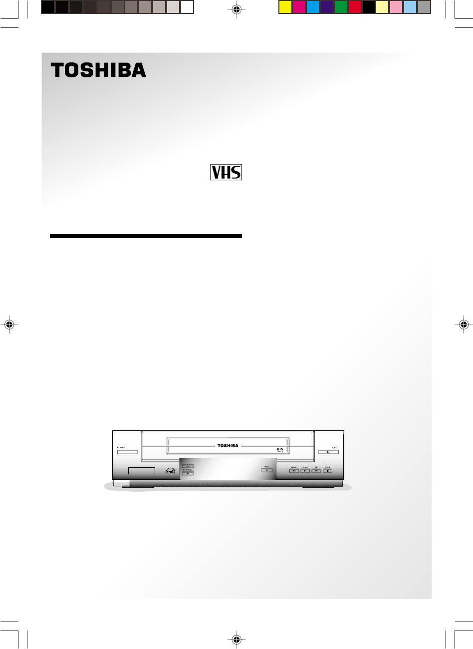
Video Cassette Recorder
W-422
OWNER’S MANUAL
HEAD
VIDEO SYSTEM
4
AUTO CLOCK SET
W-422/ENG(1-9) 9/1/01, 10:44 AM1
2
In the spaces provided below, record the Model and Serial No. located at the rear of your video
cassette recorder.
Model No. Serial No.
Retain this information for future reference.
WARNING: TO REDUCE THE RISK OF FIRE OR ELECTRIC SHOCK, DO NOT EXPOSE
THIS APPLIANCE TO RAIN
OR MOISTURE. DANGEROUS HIGH VOLTAGES ARE PRESENT INSIDE THE
ENCLOSURE. DO NOT OPEN THE CABINET. REFER SERVICING TO QUALI-
FIED PERSONNEL ONLY.
CAUTION: TO PREVENT ELECTRIC SHOCK, MATCH WIDE BLADE OF PLUG TO WIDE
SLOT, FULLY INSERT.
Note to CATV system installer:
This reminder is provided to call the CATV system installer’s attention to Article 820-40 of the NEC
that provides guidelines for proper grounding and, in particular, specifies that the cable ground shall
be connected to the grounding system of the building, as close to the point of cable entry as practical.
Copyright
It is permissible to record television programs, film, video tapes and other material only
in the event that third party copyrights and other rights are not violated.
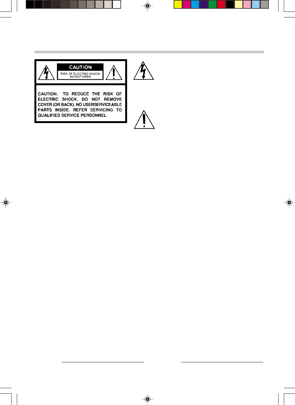
The lightning flash with arrowhead symbol,
within an equilateral triangle, is intended to
alert the user to the presence of uninsulated
“dangerous voltage” within the product’s en-
closure that may be of sufficient magnitude
to constitute a risk of electric shock to per-
sons.
The exclamation point within an equilateral
triangle is intended to alert the user to the
presence of important operating and mainte-
nance (servicing) instructions in the literature
accompanying the appliance.
SAFETY PRECAUTIONS
Product Name: Video Cassette Recorder
Model Number: W-422
FCC Notice: “Declaration of Corformity”.
This device complies with part 15 of the FCC Rules. Operation is subject to the following two
conditions: (1) This device may not cause harmful Interference, and (2) this device must accept any
interference received, including interference that may cause undesired operation.
Contact: Toshiba America Consumer Products, Inc.
Address: 1420 Toshiba Drive, Lebanon, TN 37087
Telephone: 615-449-2360
User Installer Caution: Changes or modification made to this equipment not expressly approved by
Toshiba Corporation or parties authorized by Toshiba Corporation could void the user’s authority
to operate the equipment.
W-422/ENG(1-9) 9/1/01, 10:44 AM2
3
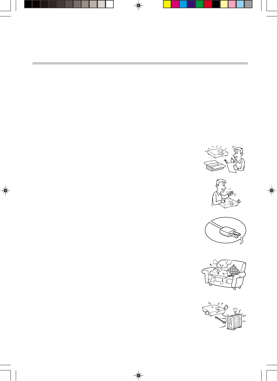
IMPORTANT PRECAUTIONS
Save Original Packing Materials
The original shipping carton and packing materials will come in handy if you ever have to ship
your VCR. For maximum protection, repack the set as it was originally packed at the factory.
Avoid Volatile Liquid
Do not use volatile liquids, such as an insect spray, near the unit.
Do not leave rubber or plastic products touching the unit for a long time. They will mar the
finish.
Moisture Condensation
Never operate this unit immediately after moving it from a cold location to a warm location.
When the VCR is exposed to such a change in temperature, moisture may condense on the
cylinder inside, one of its most crucial internal parts. To prevent the VCR from possible
damage, do not use the unit for at least 2 hours when there is an extreme or sudden change
in temperature.
Compatibility
This video cassette recorder (VCR) is compatible with any other VCR bearing the
mark. HQ VHS equipment is also compatible with existing, non-HQ VHS equipment.
INTRODUCTION
As an ENERGY STAR Partner, TOSHIBA has determined that this product or
product model meets the ENERGY STAR guidelines for energy efficiency.
®
®
W-422/ENG(1-9) 9/1/01, 10:44 AM3
4
1. Read owner’s manual
After unpacking this product, read the owner’s manual carefully, and follow all
the operating and other instructions.
2. Power Sources
This product should be operated only from the type of power source indicated
on the marking label. If you are not sure of the type of power supply to your
home, consult your product dealer or local power company. For products
intended to operate from battery power, or other sources, refer to the operating
instructions.
3. Grounding or Polarization
This product may be equipped with a polarized alternating current line plug (a
plug having one blade wider than the other). This plug will fit into the power
outlet only one way. This is a safety feature. If you are unable to insert the plug
fully into the outlet, try reversing the plug. If the plug should still fail to fit, contact
your electrician to replace your obsolete outlet. Do not defeat the safety
purpose of the polarized plug.
4. Ventilation
Slots and openings in the cabinet are provided for ventilation and to ensure
reliable operation of the product and to protect it from overheating, and these
openings must not be blocked or covered. The openings should never be
blocked by placing the product on a bed, sofa, rug or other similar surface. This
product should not be placed in a built-in installation such as a bookcase or rack
unless proper ventilation is provided or the manufacturer’s instructions have
been adhered to.
5. Heat
The product should be situated away from heat sources such as radiators, heat
registers, stoves, or other products (including amplifiers) that produce heat.
IMPORTANT SAFETY
INSTRUCTIONS
CAUTION: PLEASE READ AND OBSERVE ALL WARNINGS AND INSTRUCTIONS
GIVEN IN THIS OWNER’S MANUAL AND THOSE MARKED ON THE UNIT.
RETAIN THIS BOOKLET FOR FUTURE REFERENCE.
This set has been designed and manufactured to assure personal safety. Improper use can
result in electric shock or fire hazard. The safeguards incorporated in this unit will protect
you if you observe the following procedures for installation, use and servicing. This unit is
fully transistorized and does not contain any parts that can be repaired by the user.
DO NOT REMOVE THE CABINET COVER, OR YOU MAY BE EXPOSED TO
DANGEROUS VOLTAGE. REFER SERVICING TO QUALIFIED SERVICE PERSONNEL
ONLY.
W-422/ENG(1-9) 9/1/01, 10:44 AM4
5
6. Water and Moisture
Do not use this product near water - for example, near a bath tub, wash bowl,
kitchen sink, or laundry tub; in a wet basement; or near a swimming pool and
the like.
7. Cleaning
Unplug this product from the wall outlet before cleaning. Do not use liquid
cleaners or aerosol cleaners. Use a damp cloth for cleaning.
8. Power-Cord Protection
Power-supply cords should be routed so that they are not likely to be walked
on or pinched by items placed upon or against them, paying particular attention
to cords at plugs, convenience receptacles, and the point where they exit from
the product.
9. Overloading
Do not overload wall outlets; extension cords, or integral convenience recep-
tacles as this can result in a risk of fire or electric shock.
ANTENNA
DISCHARGE UNIT
(NEC SECTION 810-20)
EXAMPLE OF ANTENNA GROUNDING AS PER
NATIONAL ELECTRICAL CODE
GROUND
CLAMP
ANTENNA
LEAD IN
WIRE
ELECTRIC
SERVICE
EQUIPMENT
GROUNDING CONDUCTORS
(NEC SECTION 810-21)
GROUND CLAMPS
POWER SERVICE GROUNDING
ELECTRODE SYSTEM
(NEC ART 250, PART H)
NEC – NATIONAL ELECTRICAL CODE
S2898A
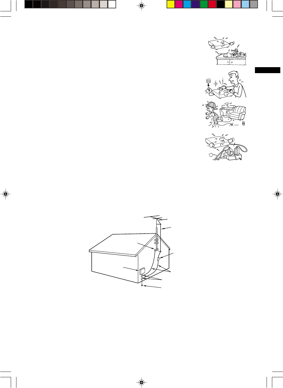
10. Outdoor Antenna Grounding
If an outside antenna or cable system is connected to the product, be sure the antenna or cable system
is grounded so as to provide some protection against voltage surges and built-up static charges. Article
810 of the National Electrical Code, ANSI/NFPA 70, provides information with regard to proper
grounding of the mast and supporting structure, grounding of the lead-in wire to an antenna discharge
unit, size of grounding conductors, location of antenna-discharge unit, connection to grounding
electrodes, and requirements for the grounding electrode.
11. Power Lines
An outside antenna system should not be located in the vicinity of overhead power lines or other electric
light or power circuits, or where it can fall into such power lines or circuits. When installing an outside
antenna system, extreme care should be taken to keep from touching such power lines or circuits as
contact with them might be fatal.
INTRODUCTION
W-422/ENG(1-9) 9/1/01, 10:44 AM5
6
16. Damage Requiring Service
Unplug this product from the wall outlet and refer servicing to qualified service personnel under the
following conditions:
a) When the power-supply cord or plug is damaged.
b) If liquid has been spilled, or objects have fallen into the product.
c) If the product has been exposed to rain or water.
d) If the product does not operate normally by following the operating instructions. Adjust only those
controls that are covered by the operating instructions as an improper adjustment of other controls
may result in damage and will often require extensive work by a qualified technician to restore the
product to its normal operation.
e) If the product has been dropped or damaged in any way.
f) When the product exhibits a distinct change in performance - this indicates a need for service.
12. Lightning
For added protection for this product during storm, or when it is left unattended
and unused for long periods of time, unplug it from the wall outlet and
disconnect the antenna or cable system. This will prevent damage to the
product due to lightning and power-line surges.
13. Object and Liquid Entry
Never push objects of any kind into this product through openings as they may
touch dangerous voltage points or short-out parts that could result in a fire or
electric shock. Never spill liquid of any kind on the product.
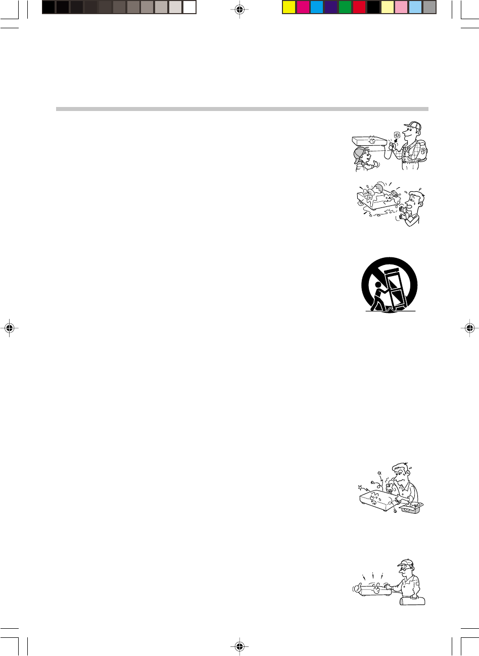
15. Accessories
Do not place this product on an unstable cart, stand, tripod, bracket, or table.
The product may fall, causing serious injury to a child or adult, and serious
damage to the product. Use only with a cart, stand, tripod, bracket, or table
recommended by the manufacturer, or sold with the product. Any mounting of
the product should follow the manufacturer’s instructions, and should use a
mounting accessory recommended by the manufacturer.
A product and cart combination should be moved with care. Quick stops,
excessive force, and uneven surfaces may cause the product and cart
combination to overturn.
14. Attachments
Do not use attachments not recommended by the product manufacturer as they may cause hazards.
17. Servicing
Do not attempt to service this product yourself as opening or removing covers
may expose you to dangerous voltage or other hazards. Refer all servicing to
qualified service personnel.
18. Replacement Parts
When replacement parts are required, be sure the service technician has used replacement parts
specified by the manufacturer or have the same characteristics as the original part. Unauthorized
substitutions may result in fire, electric shock, or other hazards.
19. Safety Check
Upon completion of any service or repairs to this product, ask the service
technician to perform safety checks to determine that the product is in proper
operating condition.
S3125A
IMPORTANT SAFETY
INSTRUCTIONS
W-422/ENG(1-9) 9/1/01, 10:44 AM6

7
INTRODUCTION
Provides important notes and general
explanation of the VCR, including names of the
buttons, jacks, etc.
SAFETY PRECAUTIONS .................... 2
IMPORTANT PRECAUTIONS ............. 3
IMPORTANT SAFETY
INSTRUCTIONS ................................... 4
Contents .............................................. 7
Identification of Controls ................... 8
• Front Panel
• Remote Control
• VCR Display
• Rear Panel
PREPARATION
Explains what you need to do before operating
the VCR.
How to Use the Remote Control ...... 10
Connections ...................................... 11
Auto Set Up ....................................... 13
Initial Settings Using On-screen
Display ............................................... 14
• Setting the Language
• Optional settings on the SET UP
screen
• Setting the Clock
Storing Channels on the VCR.......... 16
Video Cassette Use .......................... 18
PLAYBACK
Explains variable functions concerning
playback.
Playback ............................................ 19
• Basic Playback
• Double Speed Playback
Variable Speed Playback ................. 20
• Picture Search
• Still Picture
• Frame Advance
• Slow-motion Picture
Useful Functions in Tape
Operation ........................................... 22
• Counter Function
• Tape Remaining Time
• Memory Stop Feature
RECORDING
Explains recording functions.
Recording a TV Program.................. 24
• Basic Recording
• Watching a TV program while
recording another
• Skipping unnecessary scenes while
recording
• Recording off time setting
Timer Program Recording ............... 25
ADDITIONAL INFORMATION
Remote Control
for TOSHIBA TV’s............................... 28
Before Calling Service Personnel ... 29
Specifications ................................... 30
Accessories ...................................... 30
Memo ................................................. 31
LIMITED WARRANTY ....... Back cover
Contents
INTRODUCTION
W-422/ENG(1-9) 9/1/01, 10:44 AM7
8
POWER
CH/TRK
TV VOL
TV/VCR
COUNT RESE
T
TIMER
PLAY
*
FF
*
100
DISPLAY
SP/SLP
REC
19
21
14
18
REW
*
SLOW
PAUSE/STILL
ENTER
STOP
*
PROG.
EJECT
CANCEL
22
24 27
24
14
19
17
28
24
22
26
19
19
20
19
14
SLOW
PAUSE/STILL
STOP
FF
REC TIMER
VC-413
TV
VCR
POWER
I.SELECT
SP/SLP
DISPLAY
TV VOL
COUNTER
PROG. CANCEL
123
45
0
100
6
REW
PLAY
REMAIN/
RESET
COUNT
9
87
EJECT
TV
VCR
14
28
I.SELECT
24
Number buttons
17
REMAIN/COUNTER
22
ENTER
14 24
19
19
19
19
24
18
18
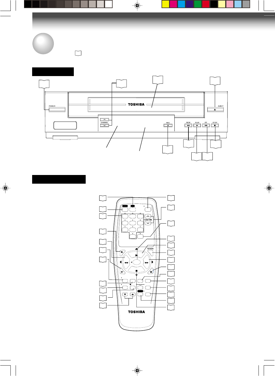
Front Panel
Remote Control
* These buttons are used to control the
cursor on the screen.
INTRODUCTION
Identification of Controls
See the page in for details.
This manual shows the names of buttons in italics.
To operate your TV
To operate this VCR.
CHANNEL
Remote
Sensor VCR Display
STOP
PLAY FF
Cassette compartment
REW
EJECT
POWER
REC
W-422/ENG(1-9) 9/1/01, 10:44 AM8
9
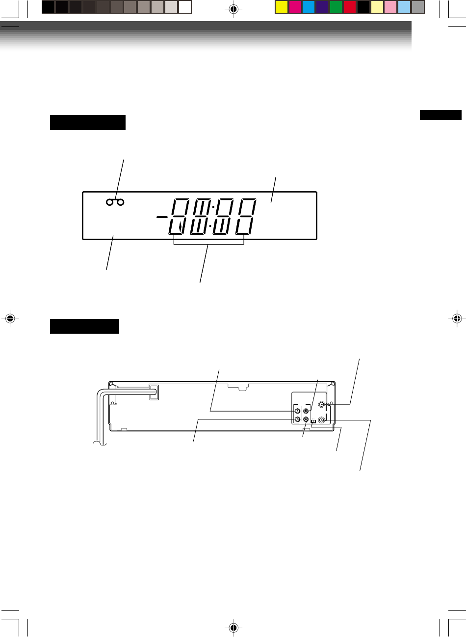
Rear Panel
Multifunctional
indicator
VCR indicator
Cassette indicator
Timer recording indicator
VCR Display
VCR
TIMER
VCR
TIMER
INTRODUCTION
CH selector (3/4)
LINE OUT AUDIO jack
LINE OUT VIDEO jack
RF IN (FROM ANT.) terminal
LINE IN AUDIO jack
RF OUT (TO TV) terminal
LINE IN VIDEO jack
CH
OUT
(
TO TV)
IN
(
FROM ANT.)
OUT IN
VIDEO
AUDIO
34
RF
To wall outlet
W-422/ENG(1-9) 9/1/01, 10:44 AM9
10
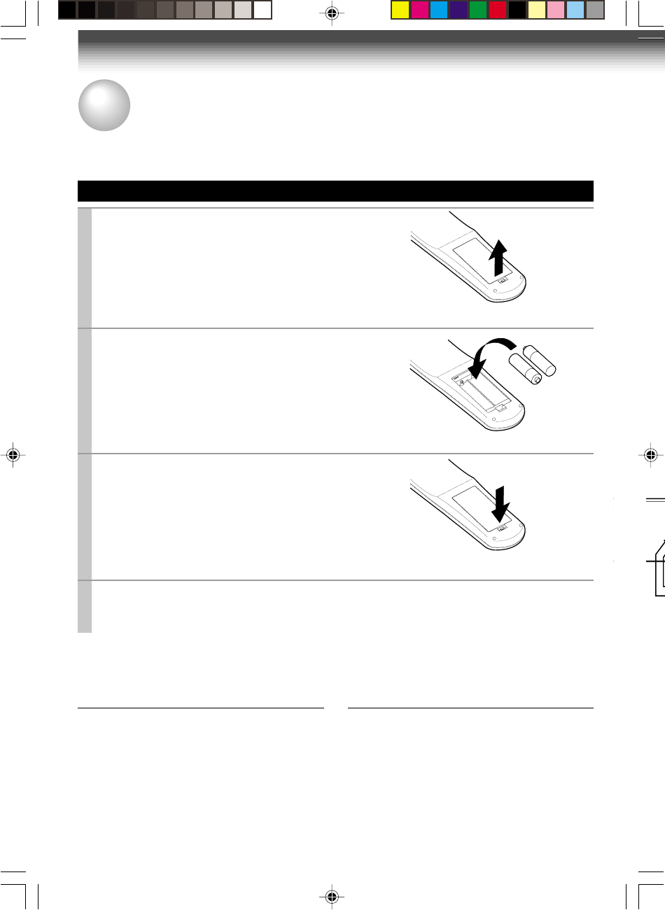
Setting up the Remote Control
1
Open the battery compartment lid on the
rear panel.
2
Install 2 batteries (“AA” size) following
the polarity diagrams.
3
Close the battery compartment lid.
4
Point the remote control at the VCR and press the buttons within the operating range.
Distance: within about 7 m from the front of the remote sensor
Angles: within about 30˚ in every direction
Notes on batteries
•The life of the batteries is about 1 year
depending on the conditions of use.
•If the remote control does not operate correctly,
replace all batteries with new ones.
•If the remote control is not to be used for a
long period of time, remove the batteries to
avoid possible damage from battery corrosion.
Caring for the remote control
•Do not expose the remote sensor of the VCR
to a strong light source such as direct sunlight
or illumination (especially high-frequency
lighting) when using the remote control.
•Be careful not to spill water on the remote
control or to place it on anything wet, and avoid
sharp impacts.
How to Use the Remote Control
This section explains how to get ready for remote control operation.
PREPARATION
+
+
W-422/ENG (10-18) 9/1/01, 10:43 AM10
11
PREPARATION
VHF UHF
VHF/UHF
OUT
(TO TV)
IN
(
FROM ANT.)
RF
CH
OUT
(
TO TV)
IN
(
FROM ANT.)
OUT IN
VIDEO
AUDIO
34
RF
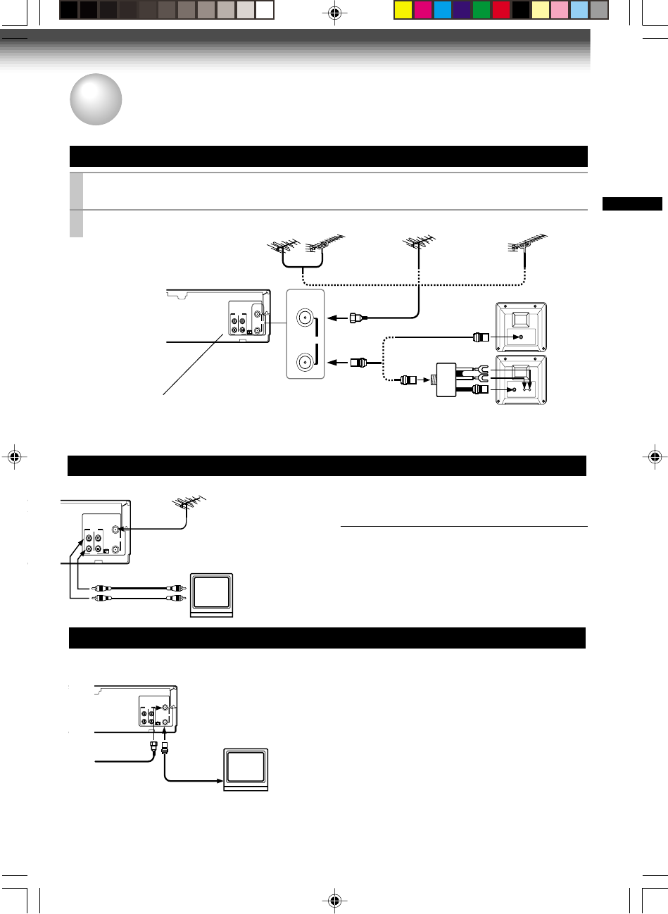
Antenna/VCR/TV Connection
1
Disconnect the antenna cable from your TV and connect it to the RF IN terminal on the
VCR.
2
Connect the RF OUT terminal to the TV.
AUDIO/VIDEO Connections
The AUDIO/VIDEO jacks are also available to connect your TV.
When connected your TV using the
AUDIO/VIDEO OUT jacks
To watch video pictures, set the video input mode
on your TV. For the video input mode, refer to the
manual of your TV.
Setting the VCR Output Channel
When the VCR is connected in this way, the VCR sends the output
signals to channel 3 or 4 on your TV. Set the output channel
selector (CH selector) of the VCR to “3” or “4”, whichever is vacant
in your area.
VHF/UHF
combination antenna VHF antenna
only
UHF antenna
only
Antenna splitter
(not supplied)
1
2
Connections
Before you use this VCR, it is necessary to connect it to your TV. Several ways of connecting are
available depending on your use of TV or cable box. Select one which is applicable to your equipment.
PREPARATION
VIDEO IN
AUDIO INLINE OUT AUDIO
CH
OUT
(
TO TV)
IN
(FROM ANT.)
OUT IN
VIDEO
AUDIO
34
RF
LINE OUT VIDEO
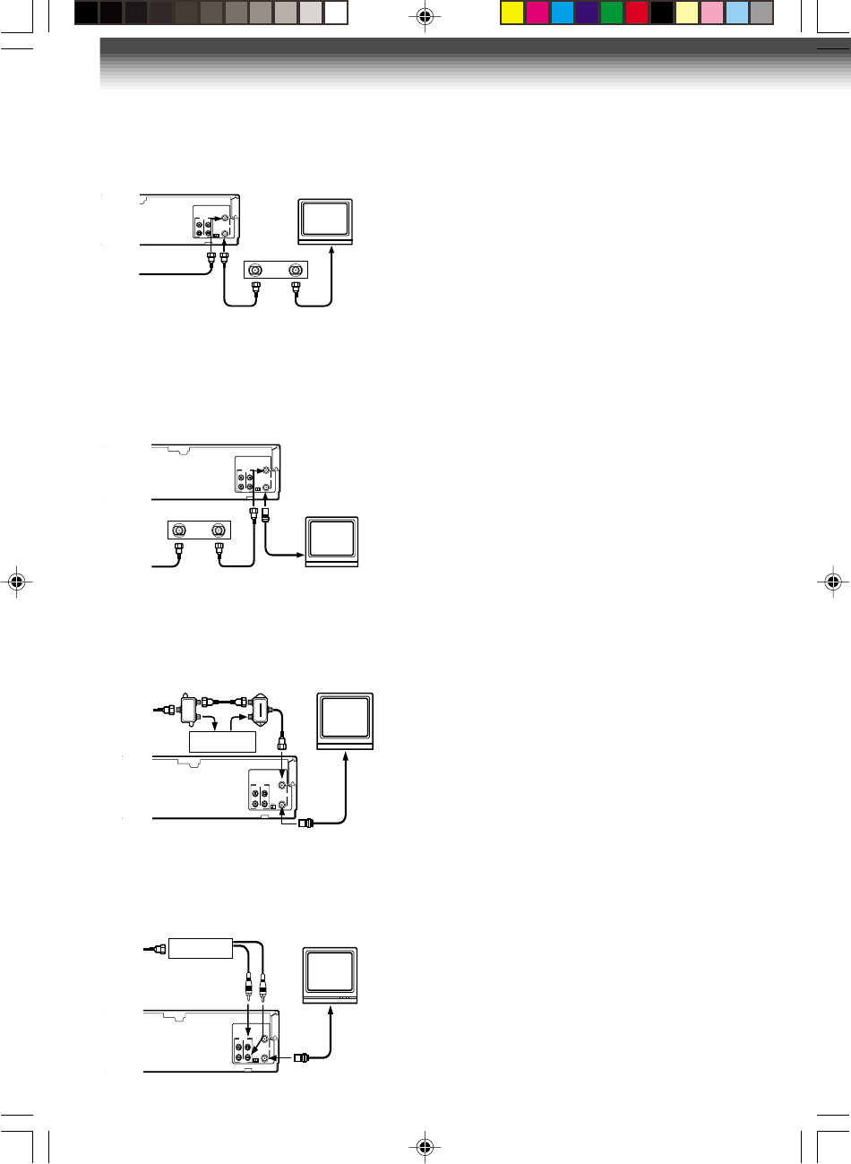
Cable Connection
Choose one of the below according to your usage of the cable box.
This set-up will enable you to:
–record an unscrambled channel.
–watch an unscrambled channel while recording it.
–record an unscrambled channel while watching
another (only when you connect a cable-
compatible TV).
You will need to:
•select TV channel 3 or 4 to receive video signals.
•to record a channel while watching another, press
TV/VCR
on the remote control to turn off the
“VCR” indicator in the VCR display and select a
desired channel on the TV (only when you connect
a cable-compatible TV).
CH
OUT
(
TO TV)
IN
(
FROM ANT.)
OUT IN
VIDEO
AUDIO
34
RF
Incoming cable
W-422/ENG (10-18) 9/1/01, 10:43 AM11
12
This set-up will enable you to:
–watch an unscrambled or scrambled channel
while recording it.
–record any channels through the cable box.
You will need to:
•set TV channel 3 or 4 to receive video signals.
(See page 11.)
•set VCR channel to the output channel of the
cable box, and select a desired cable channel
on the cable box.
•while the VCR is turned off or the “VCR”
indicator is not lit in the VCR display, set TV
channel to the output channel of the cable box.
This set-up will enable you to:
–watch an unscrambled or scrambled channel
while recording it.
–record an unscrambled channel while watching
another unscrambled channel (only when you
connect a cable-compatible TV).
•A/B switch “A”: record and watch an
unscrambled channel which
comes bypassing the cable
box.
•A/B switch “B”: record and watch a scrambled
or unscrambled channel coming
through the cable box.
Incoming cable
Cable box
OUT
IN
A/B switch
CH
OUT
(
TO TV)
IN
(
FROM ANT.)
OUT IN
VIDEO
AUDIO
34
RF
Cable box
A
B
A
B
A
B
CH
OUT
(
TO TV)
IN
(
FROM ANT.)
OUT IN
VIDEO
AUDIO
34
RF
This set-up will enable you to:
–record an unscrambled channel.
–watch an unscrambled channel while recording it.
–record an unscrambled channel while watching
another (scrambled or unscrambled).
You will need to:
•set TV channel to the output channel of the cable
box.
•turn on the cable box and select cable channel 3
or 4 according to the output channel of the VCR.
•to record a channel while watching another,
press
TV/VCR
on the remote control to turn off
the “VCR” indicator in the VCR display and select
a desired cable channel on the cable box.
Connections (continued)
CH
OUT
(
TO TV)
IN
(
FROM ANT.)
OUT IN
VIDEO
AUDIO
34
RF
CH
OUT
(
TO TV)
IN
(FROM ANT.)
OUT IN
VIDEO
AUDIO
34
RF
This set-up will enable you to:
–watch or record a channel through the cable
box via the LINE IN (AUDIO/VIDEO) jacks.
You will need to:
•press
I.SELECT
so that the VCR display
shows “L”.
Cable box
Incoming cable
Cable box
OUT
IN
W-422/ENG (10-18) 9/1/01, 10:43 AM12
13
PREPARATION
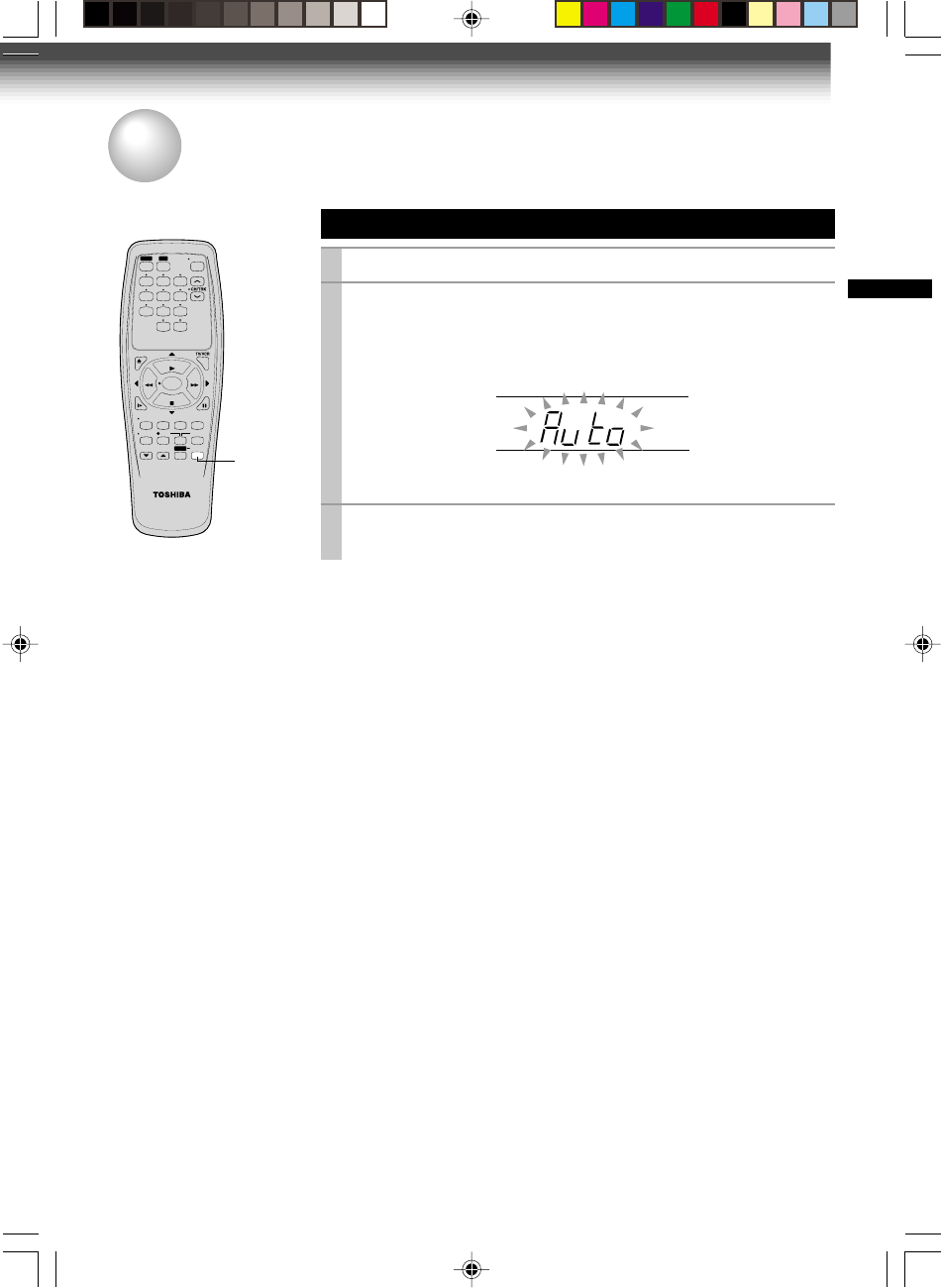
Auto Set Up
The VCR’s clock and tuner channels are set automatically when the VCR is plugged into the AC outlet.
PREPARATION
Auto Set up
1
Plug the VCR into the AC outlet
2
“Auto” blink while the VCR automatically sets the clock using
the data broadcast by the local TV stations.
While “Auto” is blinking, channel memory is also set
automatically.
3
When Auto set up has been completed, the VCR is on
standby mode.
Notes
•It may takes several minutes during the Auto set-up
•Press
CANCEL
on the remote control to cancel the auto set-up.
CANCE
L
SLOW
PAUSE/STILL
STOP
FF
REC TIMER
VC-413
TV
VCR
POWER
I.SELECT
SP/SLP
DISPLAY
TV VOL
COUNTER
PROG. CANCEL
123
45
0
100
6
REW
PLAY
REMAIN/
RESET
COUNT
9
87
EJECT
ENTER
W-422/ENG (10-18) 9/1/01, 10:43 AM13
14
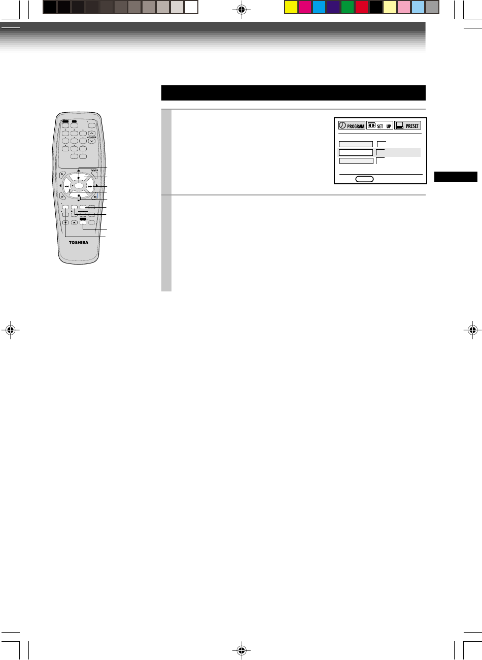
Optional settings on the SET UP screen
Other optional settings can be made. Press
ENTER
while “SET UP” is selected on the MENU screen.
The screen turns to the SET UP screen.
To exit, press
PROG.
once
.
E
n
D : PROG
TAPE LE
n
GTH
120 160 180
COU
n
TER MEM
on off
LA
n
GUAGE E
n
G FRA ESP
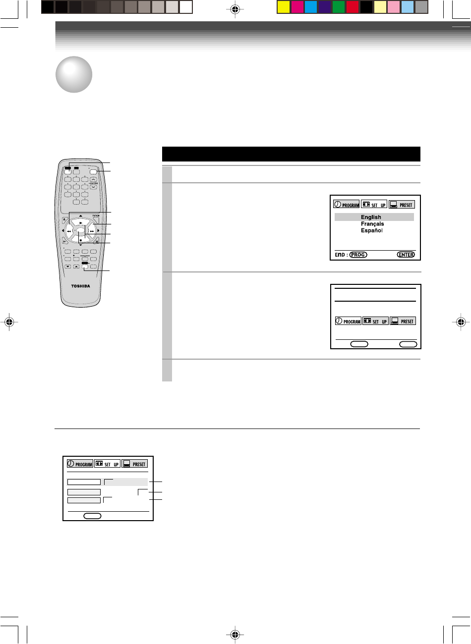
Setting the Language
1
Press
POWER
to turn on the VCR.
2
Press
PROG.
.
The following screen appears on the TV.
PREPARATION
Initial Settings Using On-screen Display
The language selection and clock setting must be set first when VCR is first plugged in or after it
encounters a power failure.
Preparation
•Turn on the TV, and select the video channel (3 or 4), or the video input mode if you made the Audio/Video
connection (page 11).
•Press
VCR
to set the remote control operating the VCR.
4
Press
PROG.
to return to the normal TV screen.
MEnU
E
n
D : PROG ENTER
POWER
VCR
FF
PLAY, STO
P
ENTER
PROG.
SLOW
PAUSE/STILL
STOP
FF
REC TIMER
VC-413
TV
VCR
POWER
I.SELECT
SP/SLP
DISPLAY
TV VOL
COUNTER
PROG. CANCEL
123
45
0
100
6
REW
PLAY
REMAIN/
RESET
COUNT
9
8
7
EJECT
REW
STOP
FF
PLAY
REW
ENTER
3
Select the language using
PLAY
or
STOP
and press
PROG.
.
The screen turns to the MENU screen.
Page 23
To change the language, move down here and set to the desired one.
Page 22
W-422/ENG (10-18) 9/1/01, 10:43 AM14
15
PREPARATION
8
Press
ENTER
to start the “AUTO” clock
set feature.
After the VCR is turned off, it automatically
updates the clock using the data broadcast
by the local TV stations.
*
The clock is
revised by
broadcasting
signal at 8:00 A.M
every morning.
9
Select the options using
FF
or
REW
.
Change the data using
PLAY
or
STOP
.
1) Set “SUMMER TIME
(Daylight-Saving Time)”.
DST start: Daylight-saving time begins on
the first Sunday in April. Because the
clock automatically changes from 2:00 AM
to 3:00 AM (forward one hour).
DST end: Daylight-saving time ends on
the last Sunday in October. The VCR
clock automatically changes from 2:00 AM
to 1:00 AM (back one hour).
remember that any part of a scheduled
Timer Recording that falls between these
two times will not be recorded.
AUTO: the VCR is using the clock data
Broadcast by the local TV stations.
IN: You want to use the DST function, and
you are leaving in the area that apply
Daylight-saving time.
OUT: You are not leaving in the area that
apply Daylight-saving time and you do not
want to use DST function.
2) Set “TIME ZONE”.
If you select “AUTO” for your time zone,
the VCR sets the clock using the first
Coordinated Universal Time information it
finds. If the time is not correct, select
another time zone or use the “MANU”
option.
3) Set “CLOCK DATA CH”.
If you don't know the clock data channel,
select “AUTO”. The VCR will scan
automatically to tune the channel carrying
the clock data.
If AUTO CLOCK SET is unsuccessful, set the
time and date through the “MANU” clock
set menu selection.
10
Press
PROG
.
.
Now the clock starts.
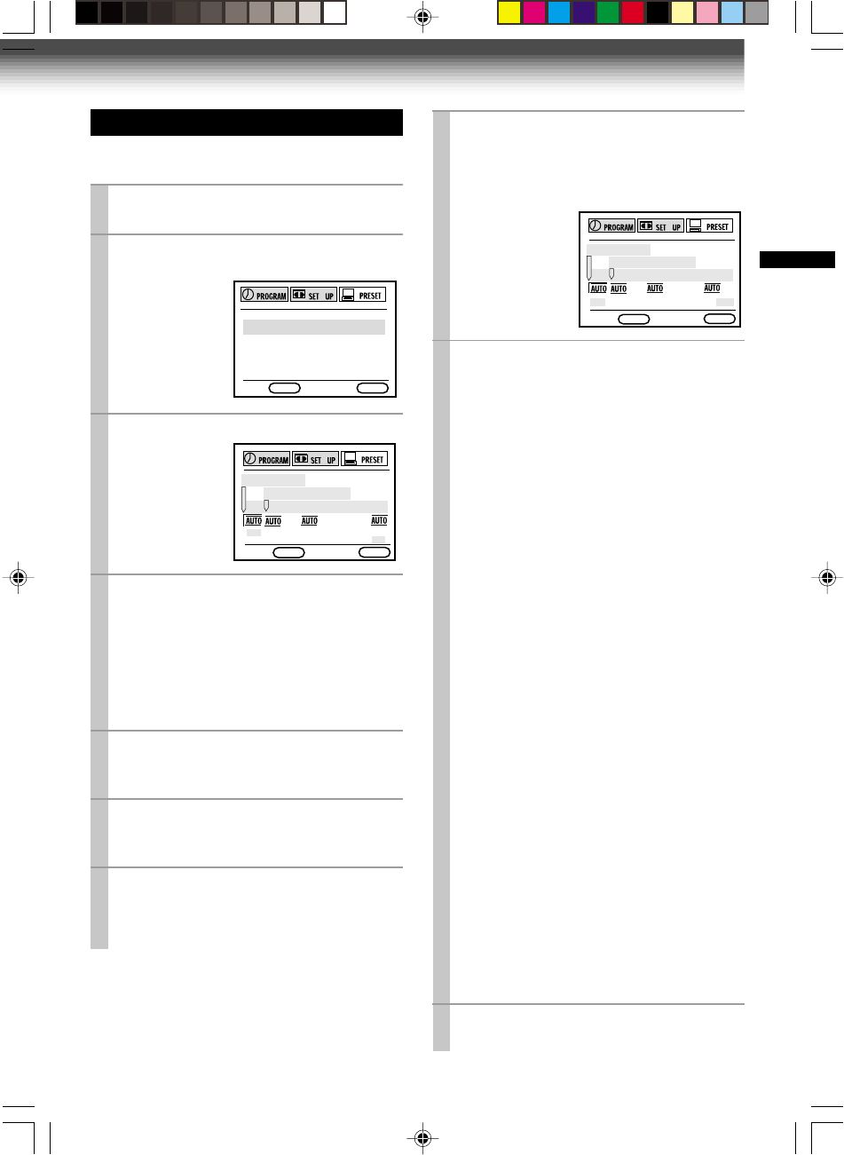
Setting the Clock
Example: To set the clock to 2:30 p.m. on
August 25 (summer time) 2001.
1
Press
PROG
.
.
The MENU screen appears on the TV.
2
Select “PRESET” using
FF
or
REW
,
and press
ENTER
.
3
Press
ENTER
to select “CLOCK SET”.
4
Select “AUTO” or “MANU” using
PLAY
or
STOP
.
AUTO
: The VCR automatically sets or
adjusts the clock.
If you select “AUTO” mode, proceed to step 8.
MANU
: You can set the clock manually.
If you select “MANU” mode, proceed to next
step.
5
Vary the digits to set the hour.
PLAY
: To increase.
STOP
: To decrease.
6
Move to the next using
FF
(To move back, press
REW
.)
7
Repeat step 5 and 6 to set the minutes,
month, day, and the year (by the last
two digits).
Proceed to step 10 to start the clock.
E n D : PROG
ENTER
CLOCK SET
SUMMER TIME
TIME ZO
n
E CH
2
SCA
nn
I
n
G
n
O
W
E n D : PROG ENTER
CLOCK SET
SUMMER TIME
TIME ZOnE CH
P R E S S E
n
T E R
T O S T A R T S E T T I
n
G
E
n
D : PROG ENTER
CLOCK SET
CH MEMORY
W-422/ENG (10-18) 9/1/01, 10:43 AM15
16
Incoming Antenna/Cable(CATV) Signals
The VCR scans through all receivable TV and CATV channels and stores only the active
ones in your area into the memory. Once the storing is finished, you can select a desired
channel using
CH/TRK
.
Preparation
•Turn on the TV, and select the video channel (3 or 4), or the video input mode if you made the Audio/Video
connection (page 11).
•Press
I.SELECT
so that the channel number will appear if “L” is displayed in the VCR display.
Incoming Antenna/Cable(CATV) Signals
1
Press
PROG
. to display the MENU screen.
2
Select “PRESET” using
FF
or
REW
,
and press
ENTER
.
3
Select “CH MEMORY” using
PLAY
or
STOP
, and press
ENTER
.
4
Set “TV/CATV“ to “TV” or “CATV” using
FF
or
REW
.
TV: To store channels received via the antenna.
CATV: To store channels received via the incoming cable.
5
Select “AUTO SCAN” using
PLAY
or
STOP
, and press
FF
to set to “ON”.
The VCR starts scanning and the
channels are stored in the VCR in
ascending order. When the scanning is
finished, the screen automatically
returns.
6
Press
PROG
.
twice to exit.
PREPARATION
Storing Channels on the VCR
This section is required if you receive only normal TV or unscrambled cable channels.
E
n
D : PROG
TV/CATV TV CATV
AUTO SCAn OFF On
ADD CH - - CH
ERASE CH - - CH
E
n
D : PROG
AUTO SCA
n
2 CH on
FF
ENTER
I.SELECT
SLOW
PAUSE/STILL
STOP
FF
REC TIMER
VC-413
TV
VCR
POWER
I.SELECT
SP/SLP
DISPLAY
TV VOL
COUNTER
PROG. CANCEL
REW
PLAY
REMAIN/
RESET
COUNT
EJECT
REW
STOP
FF
PLAY
100
REW
PLAY,STOP
1,6
123
45
0100
6
9
8
7
Number
buttons
ENTER
E
n
D : PROG ENTER
CLOCK SET
CH MEMORY
W-422/ENG (10-18) 9/1/01, 10:44 AM16
17
PREPARATION
To add channels
To erase channels
Channel reference chart
Number on the VCR
Corresponding channel number TV
CATV STD (HRC/IRC)
CH NUMBER 1 2 3 4 5 6789
–23456789
1(A-8)
234
5(A-7) 6(A-6)
7
89
10 11 12 13 14 15 16 17 18 19 20 21 22 23 24 25 26 27 28 29 30
10 11 12 13 14 15 16 17 18 19 20 21 22 23 24 25 26 27 28 29 30
10 11 12 13 A B C D E F G H I J K L M N O P Q
31 32 33 34 35 36 37 38 39 40 41 42 43 44 45 46 47 48 49 50 51
31 32 33 34 35 36 37 38 39 40 41 42 43 44 45 46 47 48 49 50 51
R S T U V W AA BB CC DD EE FF GG HH II JJ KK LL MM NN OO
52 53 54 55 56 57 58 59 60 61 62 63 64 65 66 67 68 69 70 71 …
52 53 54 55 56 57 58 59 60 61 62 63 64 65 66 67 68 69 ––
…
PP QQ RR SS TT UU VV WW XX YY ZZ AAA BBB 65 66 67 68 69 70 71 …
93 94 95 96 97 98 99 100 101 102 103 …121 122 123 124 125
–––––––––––
…–––––
93 94 A-5 A-4 A-3 A-2 A-1 100 101 102 103 …121 122 123 124 125
3) Enter a channel number of 1 to 125 using
number buttons
.
For more than 100 number, first press
100
.
For CATV channels, refer to the chart below.
(For other orders, check with your cable
company.)
4) Repeat steps 2) and 3) to add or erase
channels as necessary.
5) Press
PROG
. two times to exit.
Selecting stored channels
Once the active channels have been stored, you
can select the channels in two ways below.
Number buttons
To enter digits of the channel number.
•For one-digit number, enter 0 before.
•For more than 100 number, first press
100
.
•Each
number button
needs to be pressed
within 2 seconds.
CH/TRK buttons
To shift up or down the stored channel numbers.
CATV signals
•STD (standard) cable TV signals
•HRC (Harmonic Related Carriers) cable TV signals
•IRC (Incremental Related Carriers) cable TV signals
IRC is also called ICC (Incremental Coherent Carriers)
Adding or erasing channels
Adding channels
If a desired channel cannot be scanned
automatically because of a weak signal, it can be
added to the memory.
Erasing channels
You can erase a stored channel from the memory
if it is unnecessary.
1) Follow steps 1 to 3 of “Incoming Antenna/
CATV Signals”.
2) Select “ADD CH” or “ERASE CH” using
PLAY
or
STOP
.
E
n
D : PROG
TV/CATV TV CATV
AUTO SCAn OFF On
ADD CH - - CH
ERASE CH - - CH
TO SET CH PUSH 0~9 KEYS
E n D : PROG
TV/CATV TV CATV
AUTO SCA
n
OFF O
n
ADD CH - - CH
ERASE CH - - CH
TO SET CH PUSH 0~9 KEYS
W-422/ENG (10-18) 9/1/01, 10:44 AM17
18
Video Cassette Use
Loading a cassette
Push the cassette into the cassette compartment with the window side facing up and the
label side towards the front. The VCR is automatically turned on. The indicator will
appear in the VCR display.
Ejecting a cassette
Press
EJECT.
The cassette is ejected from the cassette compartment.
Warning
Do not insert your hands or any foreign objects into the compartment. This may result
in injury or damage. Take special care with children to avoid accidents.
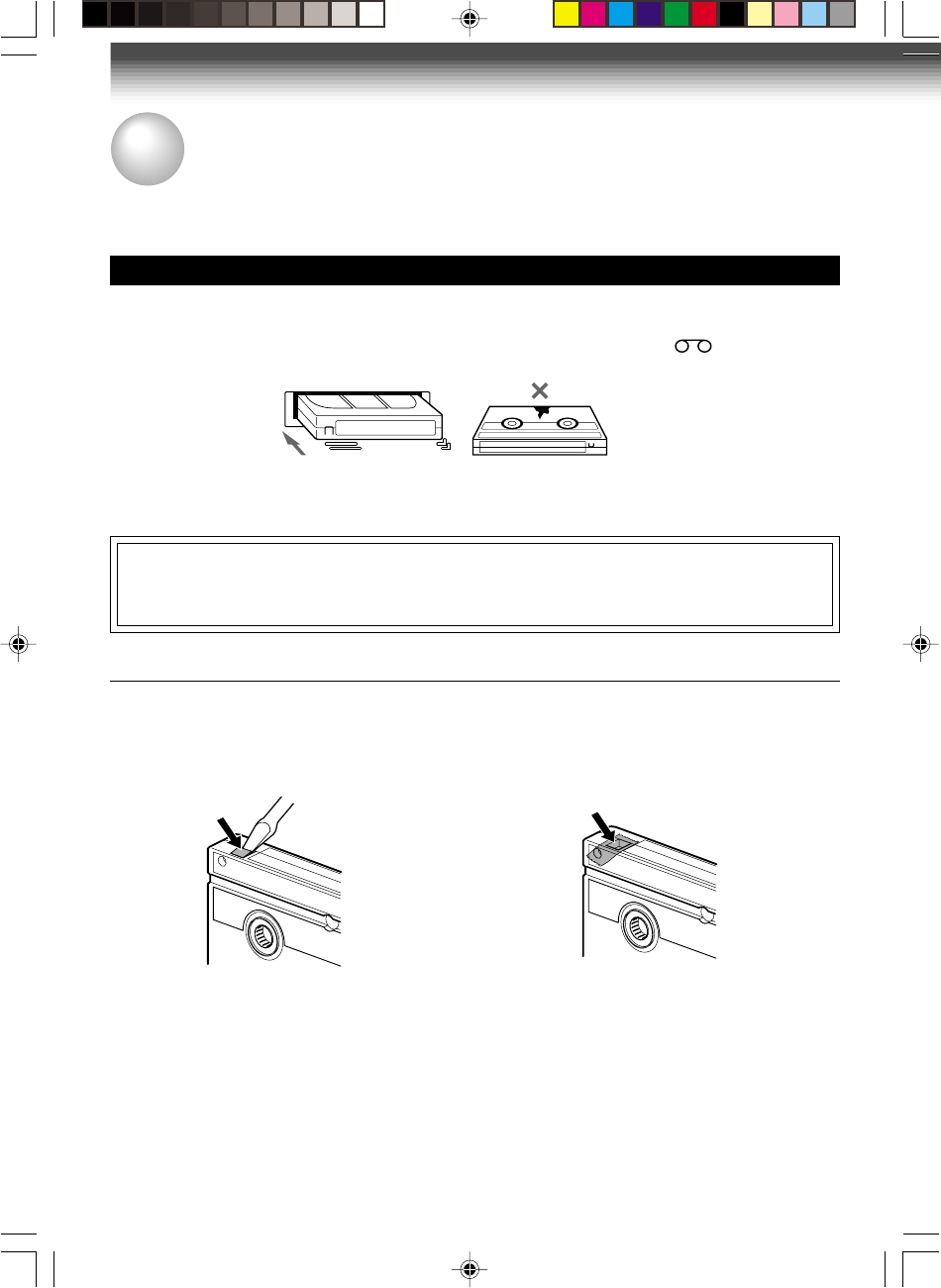
Precautions when using video cassettes
Video cassettes have a safety tab to prevent accidental erasure. If the tab has already been removed,
recording cannot be performed.
To prevent accidental erasure
Remove this safety tab with a screwdriver.
To record again
Cover the tab hole with adhesive tape.
•Avoid exposing cassettes to direct sunlight. Keep them away from heaters.
Avoid extreme humidity, vibrations or shock, strong magnetic fields (near a motor, transformer or
magnet) and dusty place.
PREPARATION
Video Cassette Use
W-422/ENG (10-18) 9/1/01, 10:44 AM18
19
PLAYBACK
Adjusting the tracking
When playback starts, the VCR automatically adjusts the tracking for clear pictures and sound
(Digital Auto Tracking).
If the VCR cannot locate the best possible tracking point, hold down one of
CH/TRK
to adjust the
tracking manually.
Notes
• During the adjusting, the playback picture and sound may be distorted.
• The digital auto tracking is activated only in the playback mode.
• The noise on the screen may not be completely eliminated depending on the tape used, especially when the
tape was recorded on another VCR.
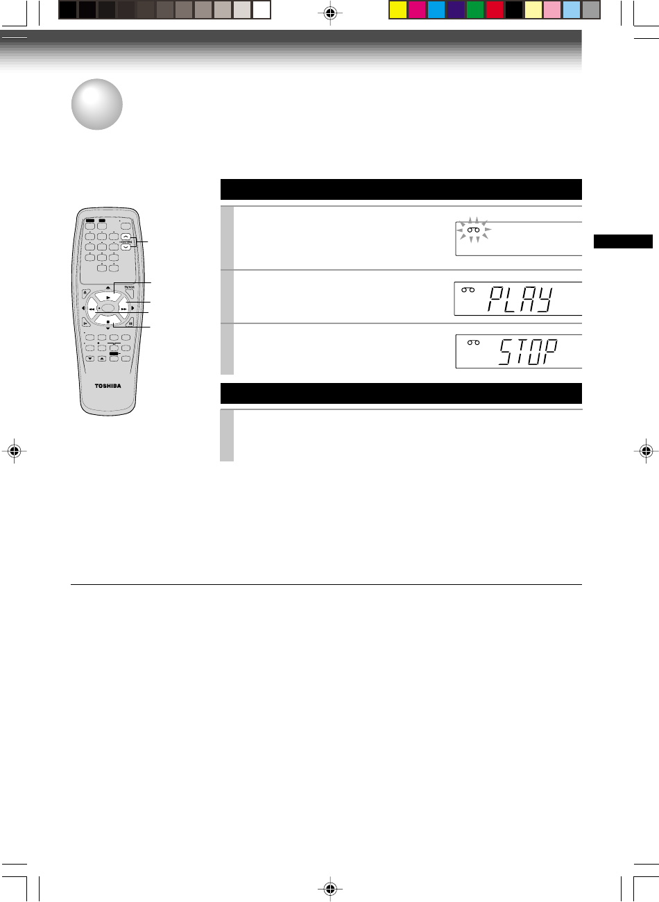
Basic Playback
1
Load a recorded cassette.
Power is turned on.
If the cassette has no safety tab,
playback starts automatically.
2
Press
PLAY
to start playback.
3
To stop playback, press
STOP
.
Rewinding / Fast-forwarding
Press
REW
or
FF
in the stop mode.
S
SLP
VCR
REC
L
TIMER
S
VCR
REC
L
TIMER
PLAYBACK
Playback
This section explains the basic playback operation.
Preparation
• Select the video channel (3 or 4) or video input mode on the TV.
• Press VCR to set the remote control operating the VCR.
S
T
VCR
L
REW
SLOW
PAUSE/STILL
STOP
FF
REC TIMER
VC-413
TV
VCR
POWER
I.SELECT
SP/SLP
DISPLAY
TV VOL
COUNTER
PROG. CANCEL
123
45
0100
6
REW
PLAY
REMAIN/
RESET
COUNT
9
8
7
EJECT
REW
STOP
FF
PLAY
CH/TR
K
2
FF
3
ENTER
1
Press
PLAY
during playback.
A tape runs at double speed
playback.
Double Speed Playback
To resume normal playback Press
PLAY
W-422/ENG(19-23) 9/1/01, 10:46 AM19
20
PLAYBACK
Variable Speed Playback
You can play back a tape at various tape speeds.
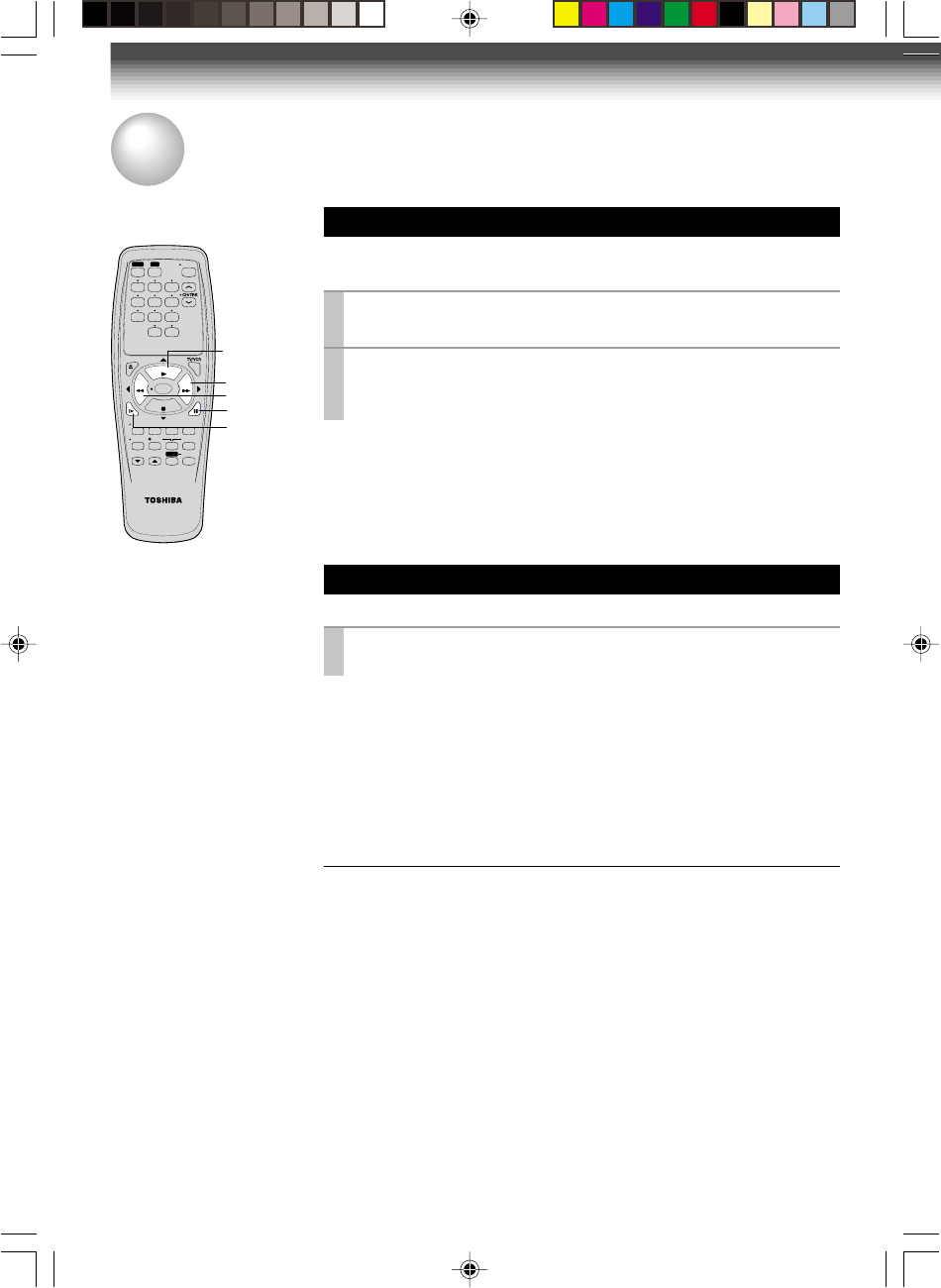
Picture Search
A tape runs at 5 times or 7 times the normal playback speed so
that you can quickly locate a particular scene.
1
Press
FF
or
REW
during playback.
The tape runs at 5 times the normal playback speed.
2
To change the tape speed to 7 times the normal playback
speed, press and hold
FF
or
REW
.
If you release it, the tape speed returns to 5 times.
Note
If you press
FF
or
REW
during picture search, the mode changes to fast-
forwarding or rewinding.
To resume normal playback
Press
PLAY
.
Still Picture
A picture freezes so that you can watch closer.
1
Press
PAUSE/STILL
during playback.
The picture freezes.
To resume normal playback
Press
PAUSE/STILL
again.
Notes
•The still mode is automatically cancelled after about 5 minutes and returns to
normal playback.
•The still picture may shake if a picture of a fast-moving object or scene is
frozen. This is not a defect in the unit.
Adjusting Still Picture Stability
If the still picture is distorted or flickers, hold down one of
CH/TRK
until
the picture becomes stable.
Note
The distortion of the still picture may not be eliminated completely.
SLOW
PAUSE/STILL
STOP
FF
REC TIMER
VC-413
TV
VCR
POWER
I.SELECT
SP/SLP
DISPLAY
TV VOL
COUNTER
PROG. CANCEL
123
45
0
100
6
REW
PLAY
REMAIN/
RESET
COUNT
9
8
7
EJECT
REW
FF
PLAY
FF
PAUSE/STILL
PLAY
REW
SLOW
ENTER
W-422/ENG(19-23) 9/1/01, 10:46 AM20

21
PLAYBACK
Frame Advance
A picture advances frame by frame.
1
Press
PLAY
during still playback.
Each time you press
PLAY
, the picture advances one frame.
Slow-motion Picture
The tape runs at 1/7th or 1/15th the normal playback speed.
1
Press
SLOW
during playback.
The tape runs at about 1/7th the normal playback speed.
Each time you press
SLOW
, the speed alternates between 1/7th and
1/15th.
To resume normal playback
Press
PLAY
.
Notes
•The slow-motion picture mode is automatically cancelled after about 5
minutes and returns to normal playback.
•The slow-motion picture may flicker up and down. This is not a defect in the
unit.
Adjusting the Tracking Manually
If the slow-motion picture is noisy, hold down one of
CH/TRK
until the
best picture is obtained.
Note
The noise in the slow-motion picture may not be eliminated completely.
To resume normal playback
Press
PAUSE/STILL
.
W-422/ENG(19-23) 9/1/01, 10:47 AM21
22
PLAYBACK
Useful Functions in Tape Operation
These functions will help your playback.
Tape Remaining Time
To view the tape remaining time in the VCR display, select the
tape length beforehand.
1
Turn on the VCR and load a cassette.
2
Press
PROG.
to display the MENU screen.
3
Select “SET UP” using
FF
or
REW
, and press
ENTER
.
4
Select the length of the tape, using
FF
or
REW
.
T120: for a T-120 tape or shorter
T160: for a T-140 or T-160 tape
T180: for a T-180 tape
5
Press
PROG
. to exit.
6
Press
REMAIN/COUNTER
.
The remaining time (“RT - : - -”) appears in the VCR display.
Notes
•The displayed remaining time is an approximation.
•The remaining time is calculated according to the tape speed (SP or SLP)
and the cassette type.
Counter Function
You can view the clock, linear time counter or tape remaining
time in the VCR display or on the TV screen.
Each time you press
REMAIN/COUNTER
, the VCR display
changes in sequence as follows:
The indication above will also appear on the TV screen by pressing
DISPLAY
. They are switchable with
REMAIN/COUNTER
.
To reset the linear time counter to “0:00:00”
The counter is automatically reset to “0:00:00” when a cassette is
ejected. If you want to reset at another point, such as the beginning of a
new recording, just press
COUNT RESET
.
Notes
•The linear time counter does not work on non-recorded portions on the tape.
•When the tape is ejected or the VCR is turned off, the display changes to
clock.
•If the tape rewinds back over “00:00”, “–” appears in the VCR display.
•The displayed time of the linear time counter is only an approximation.
→ Linear time counter → Tape remaining time (RT) → Clock
E
n
D : PROG
COU
n
TER MEM
on off
LA
n
GUAGE E
n
G FRA ESP
TAPE LE
n
GTH
120 160 180
REMAIN/
COUNTER
SLOW
PAUSE/STILL
STOP
FF
REC TIMER
VC-413
TV
VCR
POWER
I.SELECT
SP/SLP
DISPLAY
TV VOL
COUNTER
PROG. CANCEL
123
45
0
100
6
REW
PLAY
REMAIN/
RESET
COUNT
9
87
EJECT
REW
STOP
FF
PLAY
PROG.
STOP
PLAY
REW
FF
ENTER
COUNT RESE
T
DISPLAY
ENTER
W-422/ENG(19-23) 9/1/01, 10:47 AM22
23
PLAYBACK
1
On the SET UP screen, select
“COUNTER MEM.” using
PLAY
or
STOP
, and set to “ON” using
REW
or
FF
.
2
Press
PROG.
to exit.
The memory-stop feature allows you to quickly return to a
counter reading of “0H00M00S” from any point on the tape.
Memory stop is automatically turned on whenever the time
counter with memory is displayed on the TV screen. This is
convenient when you want to watch a segment of the tape
repeatedly. You may also discover other useful application for
this feature.
Notes: If you are rewinding the tape and the VCR stops at
“0H00M00S M”, press
REW
again to continue
rewinding.
If you press the
FF
(fast-forward) button and the time
counter never reaches “0H00M00S M” between that
point and the end of the tape, the VCR will continue to
fastforward to the end of the tape.
Memory Stop Feature (Zero Return)
REMAIN/
COUNTER
SLOW
PAUSE/STILL
STOP
FF
REC TIMER
VC-413
TV
VCR
POWER
I.SELECT
SP/SLP
DISPLAY
TV VOL
COUNTER
PROG. CANCEL
123
45
0
100
6
REW
PLAY
REMAIN/
RESET
COUNT
9
87
EJECT
REW
STOP
FF
PLAY
PROG.
STOP
PLAY
REW
FF
ENTER
COUNT RESE
T
DISPLAY
ENTER
E
n
D : PROG
TAPE LE
n
GTH
120 160 180
COU
n
TER MEM
on off
LA
n
GUAGE E
n
G FRA ESP
W-422/ENG(19-23) 9/1/01, 10:47 AM23
24
Watching a TV program while
recording another
1) While recording, press
TV/VCR
to turn off
“VCR” indicator.
2) Choose another channel using the channel
selector on the TV.
Skipping unnecessary scenes while
recording
Press
PAUSE/STILL
to stop recording
momentarily. To resume recording, press
PAUSE/STILL
again.
Note
The VCR automatically shifts to the stop mode if the
recording pause mode continues for 10 minutes.
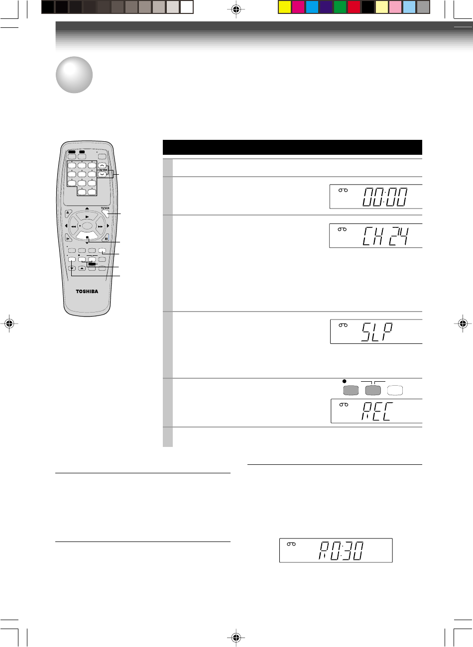
Basic Recording
1
Load a cassette with the safety tab attached.
2
Press
TV/VCR
so that the “VCR”
indicator appears in the VCR display.
3
Select a channel to record with
CHANNEL
on the VCR, or
CH/TRK
or
number buttons
on the remote
control.
If you see “L” in the VCR display, press
I.SELECT
so that the channel
number appears.
• If you record cable channels via the cable box, make the output
channel number of the cable box or “L” appear, depending on your
connection. (See pages 11 – 12.)
4
Press
SP/SLP
to select the
recording tape speed.
SP: Suitable for general recording with
better picture and sound quality.
SLP: Suitable for tripling recording time, but with less picture and
sound quality than using the SP tape speed.
5
Press
REC
on the VCR, or
simultaneously press both
REC
on
the remote control.
Recording starts.
6
Press
STOP
to stop recording.
Recording off time setting
By setting the recording off time, the recording
stops and the VCR is turned off automatically.
While recording, press simultaneously both
REC
on the remote repeatedly to set the desired off
time.
Each time you press
REC
, each half-hour up to
about 4 hours appear cyclically.
Notes
• To cancel the recording in progress, press
POWER
on the VCR
.
VCR
H
S
T
S
VCR L
S
VCR
REC
L
TIMER
S
VCR
L
TIMER
Hi-Fi
STEREO
SAP
VCR
LR
TIMER
RECORDING
Recording a TV Program
This section explains the basic recording operation.
Preparation
• Select the video channel (3 or 4) or video input mode on the TV.
To record from other
connected equipment
In step 3, press
I.SELECT
to
switch the display as follows:
L: To record via the LINE IN
jacks on the rear panel.
.
REC TIMER
6
2
5
SLOW
PAUSE/STILL
STOP
FF
REC TIMER
VC-413
TV
VCR
POWER
I.SELECT
SP/SLP
DISPLAY
TV VOL
COUNTER
PROG. CANCEL
REW
PLAY
REMAIN/
RESET
COUNT
EJECT
STOP
I.SELEC
T
4
3
123
45
0
100
6
9
8
7
ENTER
W-422/ENG (24-27) 9/1/01, 10:48 AM24
25
RECORDING
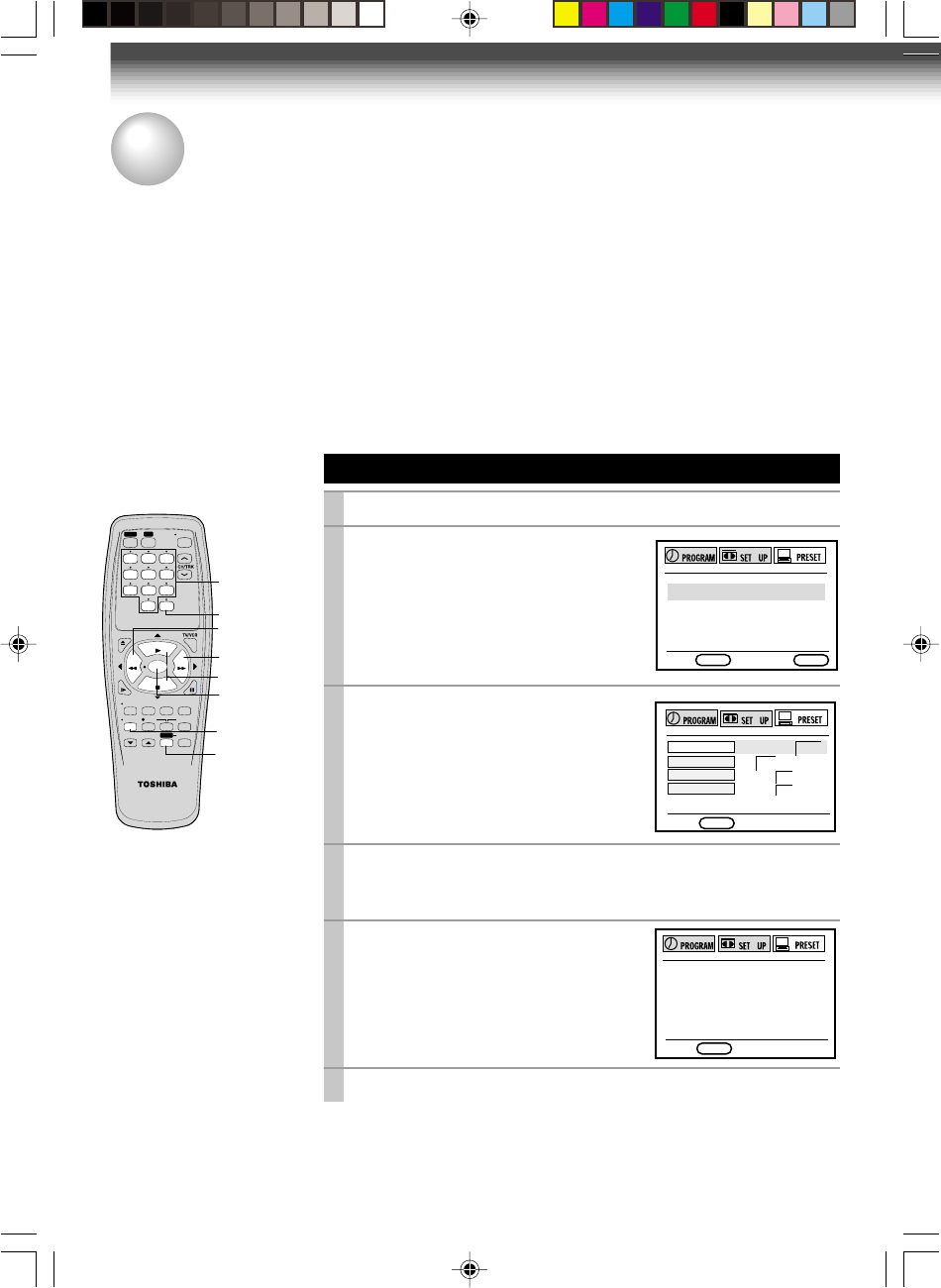
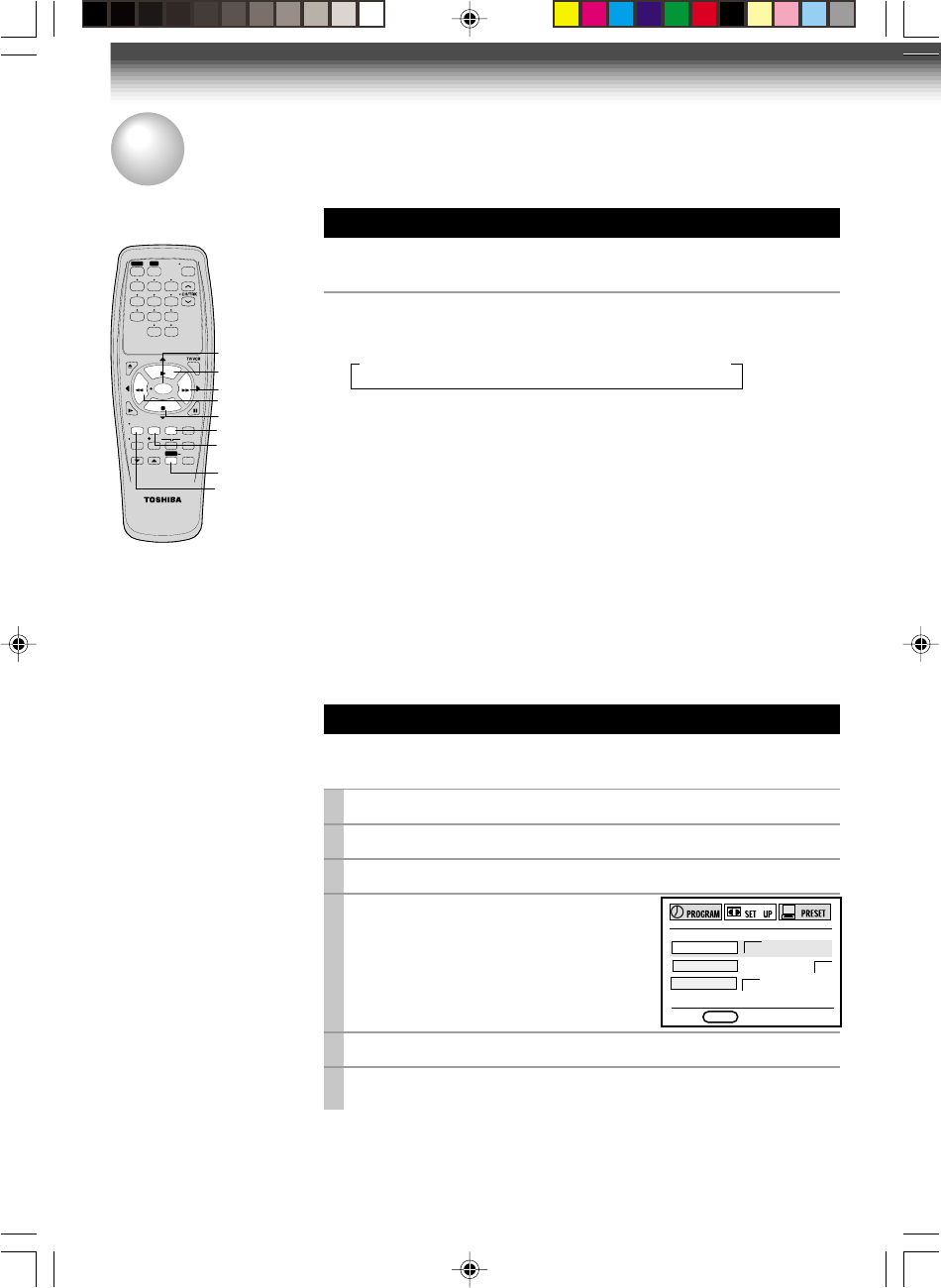
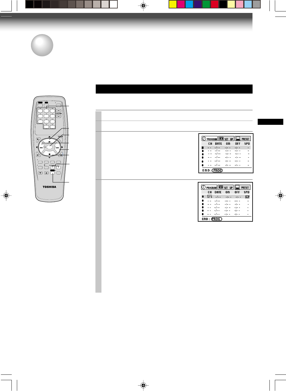
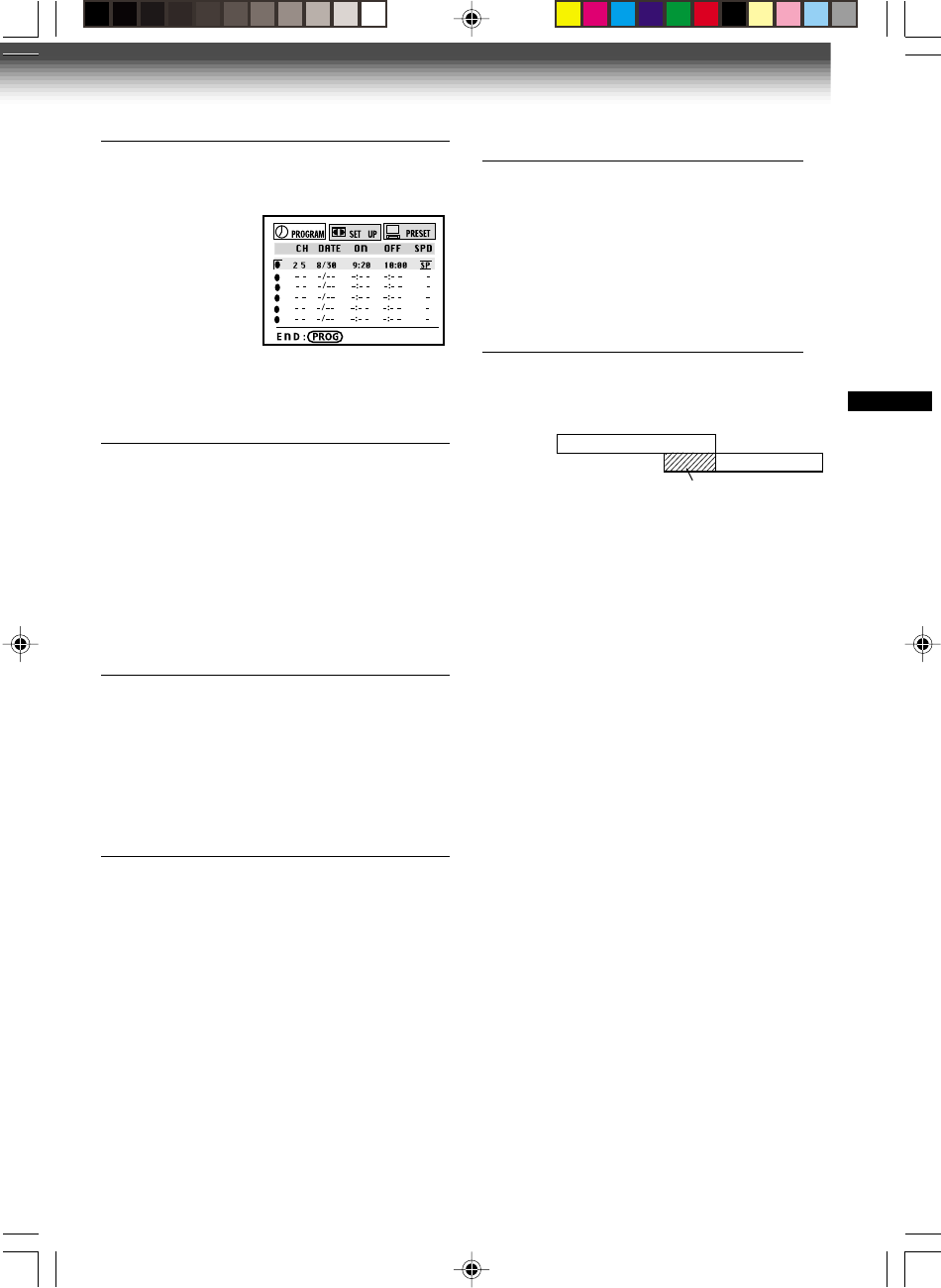
Timer Programming Procedure
Example: To record cable channel 25 in the SP tape speed from
9:20 p.m. until 10:00 p.m. on August 30. Today is August 25.
1
Load a cassette with the safety tab attached.
2
Press
PROG
. to display the MENU screen.
3
Select “PROGRAM” using
FF
or
REW
, and press
ENTER
.
4
Move to the next using
FF
, and
select the channel number 25 by
pressing
number buttons
2 and 5,
PLAY
or
STOP.
• You can make “L” appear on the channel number position by
pressing
I.SELECT
depending on your connection.
(See pages 12 ).
To make corrections:
Press
REW
to move back to the item, or
FF
to forward.
(Continued)
Timer Program Recording
The programmable timer allows you to record up to 6 different programs over one month.
Preparation
• Select the video channel (3 or 4) or video input mode on the TV.
• Make sure that the clock is set correctly (page 15).
• Store the channels on the VCR (pages 16 and 17).
RECORDING
2,9
SLOW
PAUSE/STILL
STOP
FF
REC TIMER
VC-413
TV
VCR
POWER
I.SELECT
SP/SLP
DISPLAY
TV VOL
COUNTER
PROG. CANCEL
REW
PLAY
REMAIN/
RESET
COUNT
EJECT
REW
STOP
FF
PLAY
10
123
4
0
100
6
9
8
7
5
ENTER
Number
buttons
FF
STOP
REW
ENTER
PLAY
W-422/ENG (24-27) 9/1/01, 10:48 AM25
26
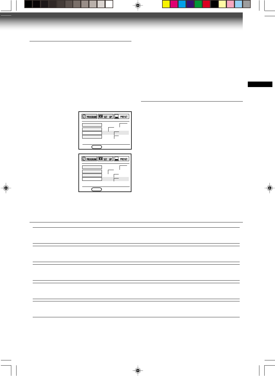
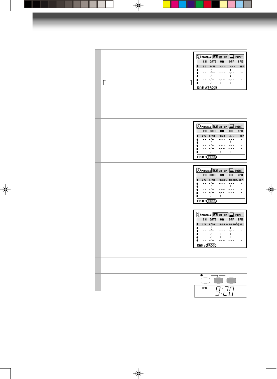
5
Move to the next using
FF
, and set
the recording date using
PLAY
or
STOP.
The date changes as follows:
[WKLYSU]…[WKLYSA]: You can record TV programs on the same
channel on the day and time every week.
[MO~FR]: You can record TV programs on the same channel on the
day and time Monday through Friday.
6
Move to the next using
FF
, and set
the hour and minutes of the
recording start time.
7
Move to the next, and set the
recording off time.
8
Move to the next, and select the
tape speed (SP) using
PLAY
or
STOP
.
For the tape speed “AUTO (Auto Speed
Select)”, see below.
To set another program, press
FF
, and
select the next line pressing
STOP.
Repeat steps 4 to 8.
9
Press
PROG.
.
Now programming is completed.
10
Press both
TIMER
simultaneously.
The power turns off and the VCR enters
the timer standby mode.
Auto Speed Select
If you are not sure the tape is long enough for
timer program recording in the SP tape speed,
set the recording tape speed to “AUTO”.
Recording starts in the SP tape speed and the
VCR automatically selects the tape speed to
record the program to the end. If the tape length
is not long enough, the tape speed automatically
changes from SP to SLP.
Notes
• Make sure that the tape length is selected correctly
according to the tape used on the SET UP screen
(page 22).
• When the SLP tape speed is selected and the tape
length is not sufficient to record the program to the
end, the program cannot be recorded to the end.
• The picture will be distorted when playing the part
where the recording tape speed is switched from
SP to SLP with the Auto Speed Select feature.
Hi-Fi
STERE
O
SAP
L
TIMER
Timer Program Recording (continued)
→ 8/25 → 9/25 → … → 7/25 →
WKLY
SU → …
MO~FR ←
WKLY
SA ←
REC TIMER
P
M
W-422/ENG (24-27) 9/1/01, 10:48 AM26
27
RECORDING
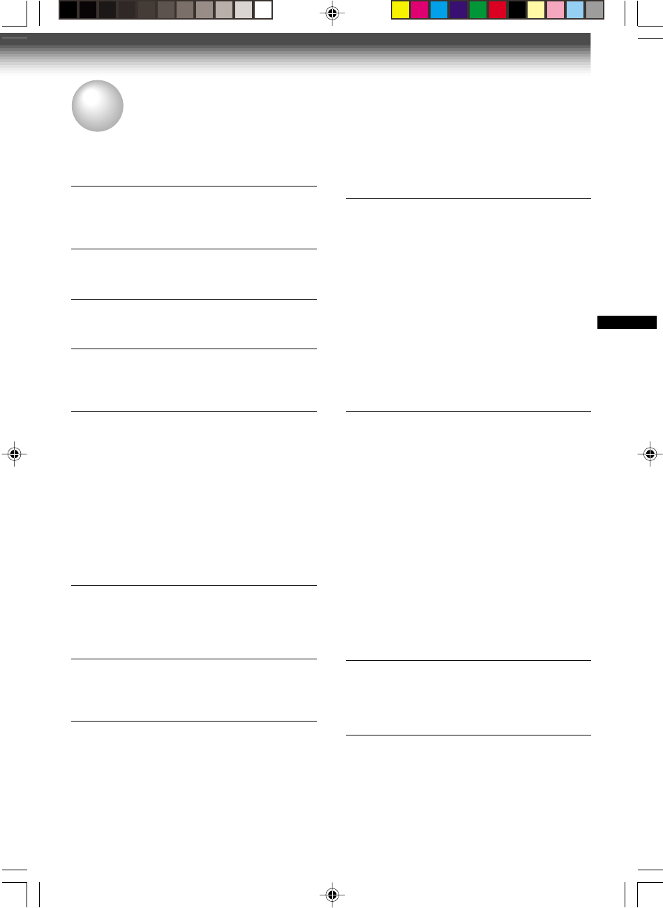
Program 1
(Start time)
Overlapped portion
(not recorded)
Program 2
(Start time)
Confirming the timer programs
Press
PROG.
during timer recording mode.
The screen for confirming will appear.
Press.
PROG.
again to exit from confirmation
page.
Changing/cancelling the timer
programs
1) If the
TIMER
indicator is lit, press both
TIMER
to turn it off, and then turn the VCR on by
pressing VCR
POWER
.
2) With steps 2 to 9, change the items.
To cancel a program, select the program you
want to cancel in step 4, and press
CANCEL.
The line is then cleared.
3) Press both
TIMER
to return to the timer
standby mode.
Error indication
The “--E--” ( Error ) indicator appears in the VCR
display if you press both
TIMER
when:
–– a cassette is not loaded.
–– the loaded cassette has no safety tab.
–– timer recording is in progress .
In these cases, a recording can not be made.
To Cancel the Timer Recording
By pressing the
POWER
button on the front
panel of the VCR, it will cancel the timer
recording and go to standby.
P
MP
M
If the power failure occurs during
the timer program recording
• When a power failure has occurred, “--:--”
appears in the VCR display. Since the
programmed contents have been cleared,
reset the clock and timer programming.
• When power has failed for a short time, the
color of the current time display blinks.
The programmed contents are not affected.
Reset the clock.
Overlaps of the programs
If two timer programs overlap, the recording
start time of program 1 has priority over the
recording off time of program 2.
W-422/ENG (24-27) 9/1/01, 10:48 AM27
28
POWER
SLOW
PAUSE/STILL
STOP
FF
REC TIMER
VC-413
TV
VCR
POWER
I.SELECT
SP/SLP
DISPLAY
TV VOL
COUNTER
PROG. CANCEL
REW
PLAY
REMAIN/
RESET
COUNT
EJECT
CH/TRK
100
100
DISPLAY
I.SELEC
T
ENTER
1
123
45
0
6
9
87
TV VOL
Number
buttons
ENTER
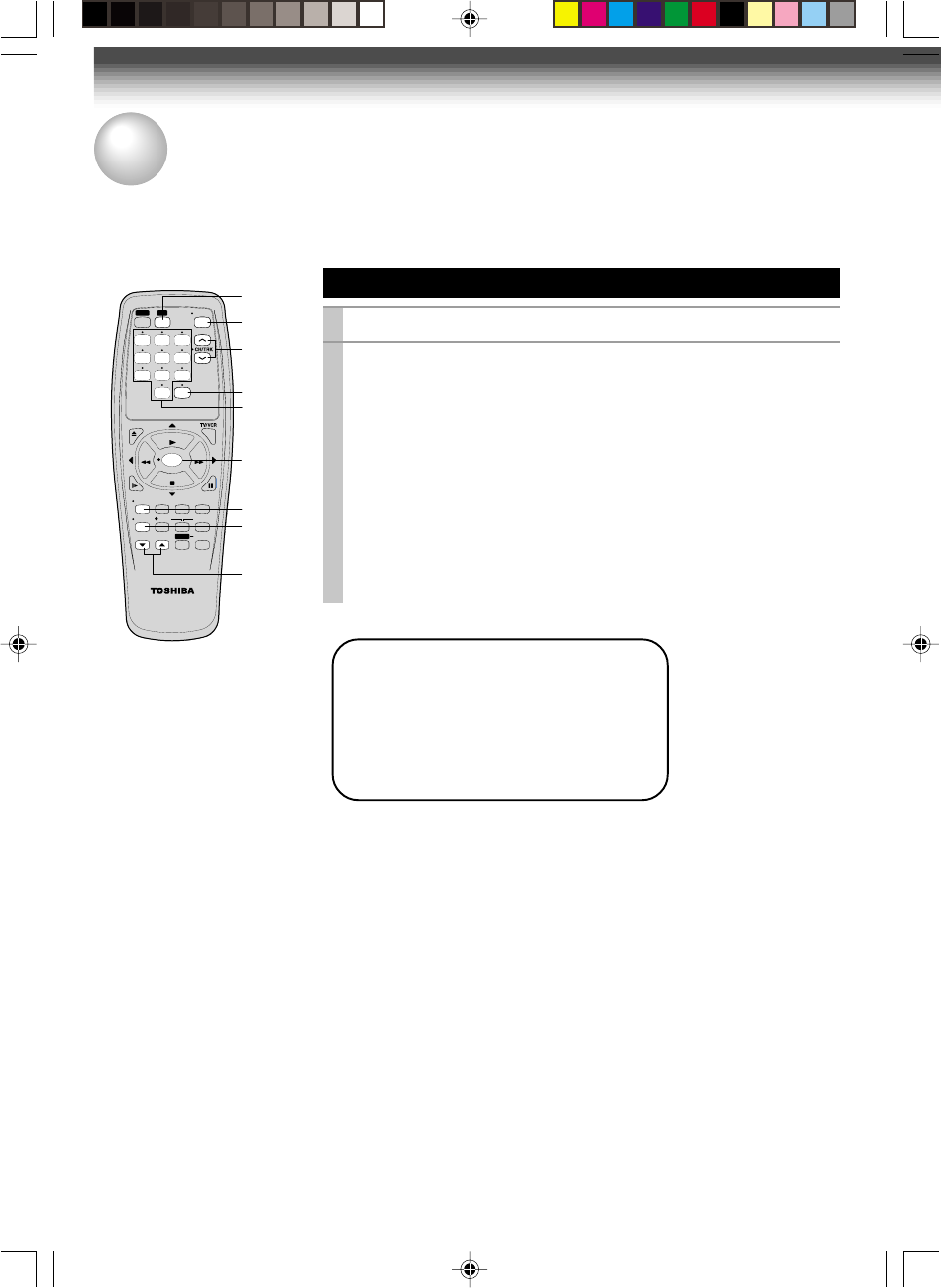
TOSHIBA TV’s control
1
Press
TV
to set the remote control operating your TV.
2
Remote Control for TOSHIBA TV’s
The remote control can control TOSHIBA TV’s.
ADDITIONAL INFORMATION
Point the remote control at your TV and use each button
listed below to make sure that your TV is operate correctly.
To turn the TV on or off
To select TV channels in the upper or lower direction.
To adjust the sound level.
To select an external source such as a VCR.
To select TV channels. When selecting channels
1 to 9, enter 0 and then the desired number.
To substitute for 100 channel key
To turn on or off TV’s screen display.
To use for the TV’s ENTER key.
POWER
CH/TRK
TV VOL
I.SELECT
Number buttons
100
DISPLAY
ENTER
Important
Some TV’s may not respond to all
the operations above, or may not
be operated at all with this remote
control. In this case, operate your
TV’s with it’s own remote control.
W-422/ENG (28-31) 9/1/01, 10:49 AM28
29
ADDITIONAL INFORMATION
ADDITIONAL INFORMATION
Before Calling Service Personnel
Check the following symptoms before requesting servicing.
No power.
• The power cord is not plugged in.
– Plug the power cord into the outlet firmly.
Although the power is on, the VCR will
not work.
• There is no cassette.
– Load a cassette. (page 18)
The clock does not work.
• There has been a power failure.
– Reset the clock. (page 15)
The timer does not work properly.
• The time is incorrect.
– Set the clock correctly. (page 15)
The picture does not appear on the TV
screen.
• The video channel or video input mode is not
set correctly.
– Set the TV channel to the video channel (3 or
4) or set the video input mode on the TV.
(page 11)
• The TV signal is weak.
– Adjust the antenna direction or use an
optional antenna booster.
• The power cord is not plugged in.
– Plug the power cord into the outlet firmly.
The picture does not appear on the TV
screen during recording and playback.
• The video channel or VCR mode is not set
correctly.
– Press
TV/VCR
to select the VCR mode and
set the TV channel to 3 or 4. (pages 11, 24)
The VCR does not record.
• The loaded cassette has no safety tab.
– Use a cassette with a safety tab or cover the
hole with adhesive tape. (page 18)
The playback picture is poor.
• Tracking is not set appropriately.
– Adjust the tracking manually. (page 19)
• The video heads are dirty.
– Clean the video heads with a commercially
available cleaning tape.
The timer recording function does not
work.
• There is an error in programming.
– Reset the timer recording program. (page 27)
• There is no cassette in the VCR.
– Load a cassette with the safety tab attached.
(page 18)
• The cassette does not have the safety tab.
– Use another cassette with a safety tab or
cover the hole with adhesive tape. (page 18)
• The timer indicator is not displayed.
– Press both
TIMER
simultaneously. (page 26)
• There has been a power failure.
– Reset the clock. (page 15)
The remote control does not work
properly.
• The batteries are exhausted.
– Replace all batteries. (page 10)
• The remote control is operated beyond the
operating range.
– Make sure the remote control is within 30° of
the remote sensor on the VCR. (page 10)
• Too far from the VCR.
– Use the remote control within 7 m from the
front of the VCR. (page 10)
• An obstacle may be in the way of the operation.
– Remove the obstacle.
• The operating mode of the remote control is not
set correctly.
– Press
VCR
or
TV
depending on the
equipment you want to operate. (pages 14)
The cassette is ejected immediately after
it is loaded.
• The cassette was inserted with the label side
not paralleling the compartment.
– Reload it carefully. (page 18)
The cassette does not go into the cassette
compartment.
• There is already a cassette in the VCR.
– Eject the cassette and reload the new one.
(page 18)
W-422/ENG (28-31) 9/1/01, 10:49 AM29

30
Specifications
Accessories
Antenna cable ....................................... 1
Remote control ..................................... 1
Batteries (AA) .................................... 2
Designs and specifications are subject to change without notice.
Power Supply: 120 V AC, 60 Hz
Power consumption: 16 W
External dimensions: 360 x 94 x 252mm (W.H.D.)
Mass: 3.0 kg
Channels received: VHF: Channels 2–13
UHF: Channels 14–69
CATV: Channels A7-A1,A-CCC, 66-125
Antenna input/output terminals: UHF/VHF: 75 Ω F type connector
Signal system: Standard NTSC
Recording/Playback system: Recording: VHS format (SP, SLP)
Playback: VHS format (SP, LP, SLP)
Cassette: Video cassette with mark
Tape speed: SLP: 11.1 mm/s, SP: 33.4 mm/s
Video recording/playback time: SLP: 480 minutes, SP: 160 minutes (When T-160
video cassette is used.)
Fast forward/rewind time: Within approx. 60 s (When T-120 video cassette is used.)
Video input: 1 V (p-p), 75 Ω, unbalanced, negative sync., pin
jack
Video output: 1 V (p-p), 75 Ω, unbalanced, negative sync., pin
jack
Audio input: Line input: 308 mV (rms), more than 47 kΩ, pin
jack
Audio output: Line output: 308 mV (rms), less than 4.7 kΩ, pin
jack
Utilization conditions: Temperature: 5°C to 40°C
Humidity: less than RH 80%
W-422/ENG (28-31) 9/1/01, 10:49 AM30

MEMO
31
W-422/ENG (28-31) 9/1/01, 10:49 AM31

32
LIMITED WARRANTY
TOSHIBA VIDEO CASSETTE RECORDER
Toshiba America Consumer Products, Inc. (“TACP”)
and Toshiba Hawaii Inc. (“THI”) make the following
limited warranties. These limited warranties extend
to the original consumer purchaser or any person
receiving this set as a gift from the original consumer
purchaser and to no other purchaser or transferee.
Limited Ninety (90) Day Warranty
TACP/THI warrant this product against defects in
materials or workmanship for a period of ninety days
after the date of original retail purchase. During this
period, TACP/THI will repair a defective product or
part, without charge to you. You must deliver the entire
product to a TACP/THI Authorized Service Station.
You are responsible for all transportation and insurance
charges for the set to and from the Authorized Service
Station.
Limited One (1) Year Warranty
TACP/THI further warrant the parts in this product
against defects in materials or workmanship for a
period of one (1) year after the date of original retail
purchase. During this period, TACP/THI will replace a
defective part without charge to you, except that if a
defective part is replaced after ninety (90) days from
the date of the original retail purchase, you pay labor
charges involved in the replacement. You must also
deliver the entire product to a TACP/THI Authorized
Service Station. You are responsible for all
transportation and insurance charges for the set to
and from the Authorized Service Station.
Rental Units
The warranty for rental units begin with the first rental
or thirty (30) days from the date of shipment to the
rental firm, whichever comes first.
Commercial Units
Products sold and used for commercial use have a
limited ninety (90) day warranty for all parts and labor.
Owner’s Manual and Demographic Card
You should read the owner’s manual thoroughly before
operating this product. You should complete and mail
the enclosed Demographic card within ten (10) days
after you, or the person who has given you this product
as a gift, purchased this product. This is one way to
enable TACP/THI to provide you with better customer
service and improved products. Failure to return the
card will not affect your rights under this warranty.
Your Responsibility
The above warranties are subject to the following
conditions:
(1) You must retain your bill of sale or provide other
proof of purchase.
(2) You must notify an Authorized TACP/THI Service
Station within thirty (30) days after you discover a
defective product or part.
(3) All warranty servicing of this product must be
made by an Authorized TACP/THI Service Station.
(4) These warranties are effective only if the product is
purchased and operated in the U.S.A or Puerto
Rico.
(5) Labor service charges for set installation. Set up,
adjustment of customer controls and installation
of repair or antenna systems are not covered by
this warranty. Reception problems caused by
inadequate antenna systems are your
responsibility.
(6) Warranties extend only to defects in materials or
workmanship as limited above and do not extend
to any product or parts which have been lost or
discarded by you or to damage to products or
parts caused by misuse, accident, damage caused
by Acts of God, such as lightning or fluctuations in
electric power, improper installation, improper
maintenance or use in violation of instructions
furnished by us; or to units which have been
altered or modified without authorization of TACP/
THI or to damage to products or parts there of
which have had the serial number removed,
altered, defaced or rendered illegible.
(7) At you option, after the warranty period has expired
in the U.S.A. Call (800)-631-3811 to receive
information concerning an exchange price.
Payment must be enclosed with the product in the
form of a certified check or money order and
forward your product to:
Toshiba America Consumer Products Inc.
Returns Center
1420C Toshiba Dr.
Lebanon, TN 37087
(8) Upon receipt we will, at our option, replace your
unit with a new or refurbished unit of equal value.
Features may not be identical to your original
product.
(9) Physically damaged units are not acceptable for
repair or exchange in or out of warranty and will be
returned as received.
W-422/ENG (28-31) 9/1/01, 10:49 AM32
33
ADDITIONAL INFORMATION
LIMITED WARRANTY (continued)
How to Obtain Warranty Service
(1)Refer to the troubleshooting guide in your owner's manual. This check list may solve your problem.
(2)Call the TACP toll free number 800-631-3811 within (30) days after you find a defective product or part.
(3)Arrange for the delivery of the product to the Authorized TACP/THI Service Station. Products shipped to
the Service Station must be insured and safely and securely packed, preferably in the original shipping
carton, and a letter explaining the defect and also a copy of the bill of sale or other proof of purchase must
be enclosed.
Toll Free
800-631-3811
In the Continental United States contact: In Hawaii contact
Toshiba Hawaii
327 Kamakee Street,
Honolulu, HA 96814
(808)-591-8377
All warranties implied by state law, including the implied warranties of merchantability and fitness for a particular
purpose, are expressly limited to the duration of the limited warranties set forth above. With the exception of any
warranties implied by state law as hereby limited, the foregoing warranty is exclusive and in lieu of all other
warranties, guarantees, agreements and similar obligations of manufacturer or seller with respect to the repair
or replacement of any parts. In no event shall TACP/THI be liable for consequential or incidental damages.
No person, agent, distributor, dealer or company is authorized to change, modify or extend the terms of these
warranties in any manner whatsoever. The time within action must be commenced to enforce any obligation of
TACP/THI arising under the warranty or under any statute, or law of the United States or any state thereof, is hereby
limited to ninety (90) days from the date you discover or should have discovered the defect. This limitation does
not apply to implied warranties arising under state law. This warranty gives you specific legal rights and you may
also have other rights which may vary from state to state. Some states do not allow limitation on how long an
implied warranty lasts, when an action may be brought or the exclusion or limitation of incidental or consequential
damages, so the above provisions may not apply to you.
ATTENTION CANADIAN CONSUMERS:
Canadian consumers are requested to complete the special Canadian “Warranty Registration Form” enclosed
and forward this completed form with a copy of bill of sale to TOSHIBA OF CANADA to “Register and Validate”
their warranty. Product must be purchased from an Authorized Canadian Dealer.
Products purchased in the U.S.A and used in Canada are not covered by these warranties.
IMPORTANT: PACKING AND SHIPPING INSTRUCTION
When you send the product to a Service Station, you should use the original carton box and packing material, then
insert the original carton box containing the unite into another carton, using more packing material.
Printed in Indonesia
AC68-01085A
W-422/ENG (28-31) 9/1/01, 10:49 AM33