Samsung Electronics Co SCWR500 CELLULAR CDMA WLL TERMINAL User Manual fcc title
Samsung Electronics Co Ltd CELLULAR CDMA WLL TERMINAL fcc title
Contents
- 1. Users Manual
- 2. Users Manual Warning Statement
Users Manual
ELECTRONICS
Printed in Korea
Code No.: GH68-00237A
’99/1 Rev 1 0(ENG)
USER’S MANUAL
CDMA
WIRELESS LOCAL LOOP
TELEPHONE
SCW-R500/510
CDMA
WIRELESS LOCAL LOOP
TELEPHONE
SCW-R500/510
SCW-R500 1/9/99 12:06 PM Page b

Safety Precautions–––––––––––––––––––––––––––––2
FCC NOTE––––––––––––––––––––––––––––––––––––3
Checking Parts––––––––––––––––––––––––––––––––4
Terminal Information –––––––––––––––––––––––––––5
Setting Up Your Terminal –––––––––––––––––––––––6
Basic Operation
Making Calls–––––––––––––––––––––––––––––12
Receiving Calls–––––––––––––––––––––––––––12
Advanced Features
Adjusting Volume –––––––––––––––––––––––––14
Terminal Reset –––––––––––––––––––––––––––14
Restricting use of the phone–––––––––––––––––15
Setting Warning Beeps–––––––––––––––––––––15
Changing the Lock Code––––––––––––––––––––16
Optional Features
Call Waiting –––––––––––––––––––––––––––––18
Three-Way Calling ––––––––––––––––––––––––18
Call Forwarding–––––––––––––––––––––––––––18
Caller ID ––––––––––––––––––––––––––––––––18
Voice Mail Service ––––––––––––––––––––––––18
Miscellaneous
Menu Options Table –––––––––––––––––––––––20
Troubleshooting ––––––––––––––––––––––––––22
Specifications––––––––––––––––––––––––––––23
TABLE OF CONTENTS
FEATURES
Description
The Fixed Wireless Terminal(FWT)s are next generation
telecommunication terminals that provide the economic efficiency of
wireless and integrated service of wireline.
Samsung SCW-R500 & SCW-R510 terminals connect traditional wired
telephones to a wireless base station which delivers the call to the public
telephone network, instead of direct wired connection the network.
Due to its wireless characters : the user can easily install the terminal and
can relocate it anywhere within the serviced local area. It is especially very
convenient to use in areas where the wired telephone installation is
difficult.
The terminals will offer you with such clear digital voice quality and
various network service features that you will not know the difference with
a conventional telephone.
The terminal was designed to either be used on a desk or attached to the
wall.
1Incoming Call Light
2Received Signal
Strength Indicator
3Adjusting Volume
4External Power
Supply(optional)
SCW-R500 1/9/99 12:06 PM Page d
FCC NOTESAFETY PRECAUTIONS
1Avoid places where there are dust, gas or fire.
2Do not shake, hit or impact the phone.
3If you wish to cleanse the outside of the terminal, use only a soft,
dry cloth. Such chemicals as alcohol, benzine or acetone can dam-
age the surface of the terminal.
4Do not twist or pull the cord out of the terminal.
5Do not disassemble the FWT as you please.
6DO NOT use the power adaptor if:
• The power cord is damaged.
• The terminal has been dropped or damaged in any way.
7Use only the SAMSUNG provided adaptor. Do not use the
SAMSUNG adaptor for any other usage.
8Use only the SAMSUNG provided antenna. Do not use the antenna
for any other usage.
9Do not install the terminal near water, for example, near a bath tub,
sink, wet basement, or swimming pool.
10 Do not allow children to play with any radio equipment
containing a transmitter. Children could hurt themselves or
others (by poking themselves or others in the eye with the
antenna. for example). Children could also damage the FWT.
NOTE : The input voltage and the shape of the plug on this terminal
may vary from country to country.
This device complies with part 15 of the FCC rules.
Operation is subject to the following two conditions:
1) The device may not cause harmful interference.
2) This device must accept any interference received,
including interference that may cause undesired
operation. Privacy of communication may not be
ensured when using this phone.
SCW-R500 1/9/99 12:06 PM Page 2
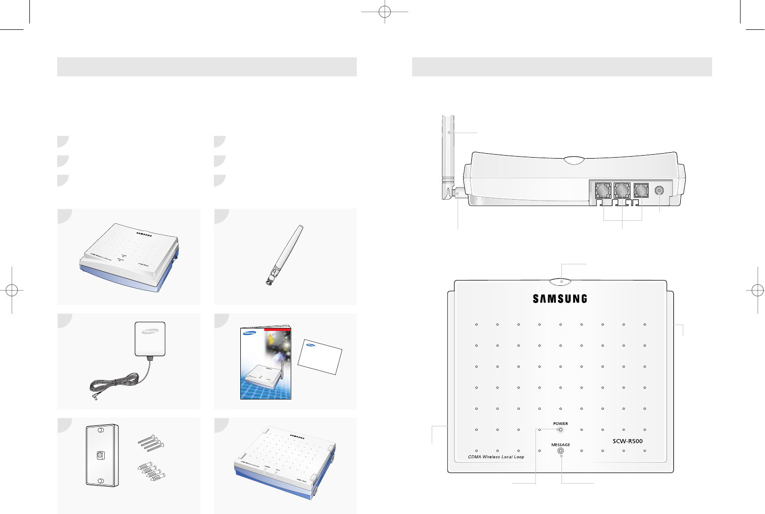
Once you have unpacked your consumer package, check to make sure that
you have all the parts shown below.
If any piece is missing or broken, please call your dealer.
FWT Terminal Antenna
AC Adaptor
User's Manual, Quick Reference Card
Wall Mountable Bracket External Power Supply(Optional)
Wall Mounting Screws and Caps
TERMINAL INFORMATION
Antenna
Antenna Connector RJ-11 Phone Port
Power
Connector
CHECKING PARTS
1 4
2 5
3 6
1 4
2 5
3 6
Wall Mountable Bracket.
Wall Mounting Screws and Caps Option
Voice mail LED
RSSI LED
ANT
Connector
Power LED
RS-232C
Connector
SCW-R500/510
Quick Reference Card
ELECTRON
USER’S MANUAL
CDMA
WIRELESS LOCAL LOOP
TELEPHONE
SCW-R500/510
CDMA
WIRELESS LOCAL LOOP
TELEPHONE
SCW-R500/510
ELECTRO
ELECTRON
SCW-R500 1/9/99 12:06 PM Page 4
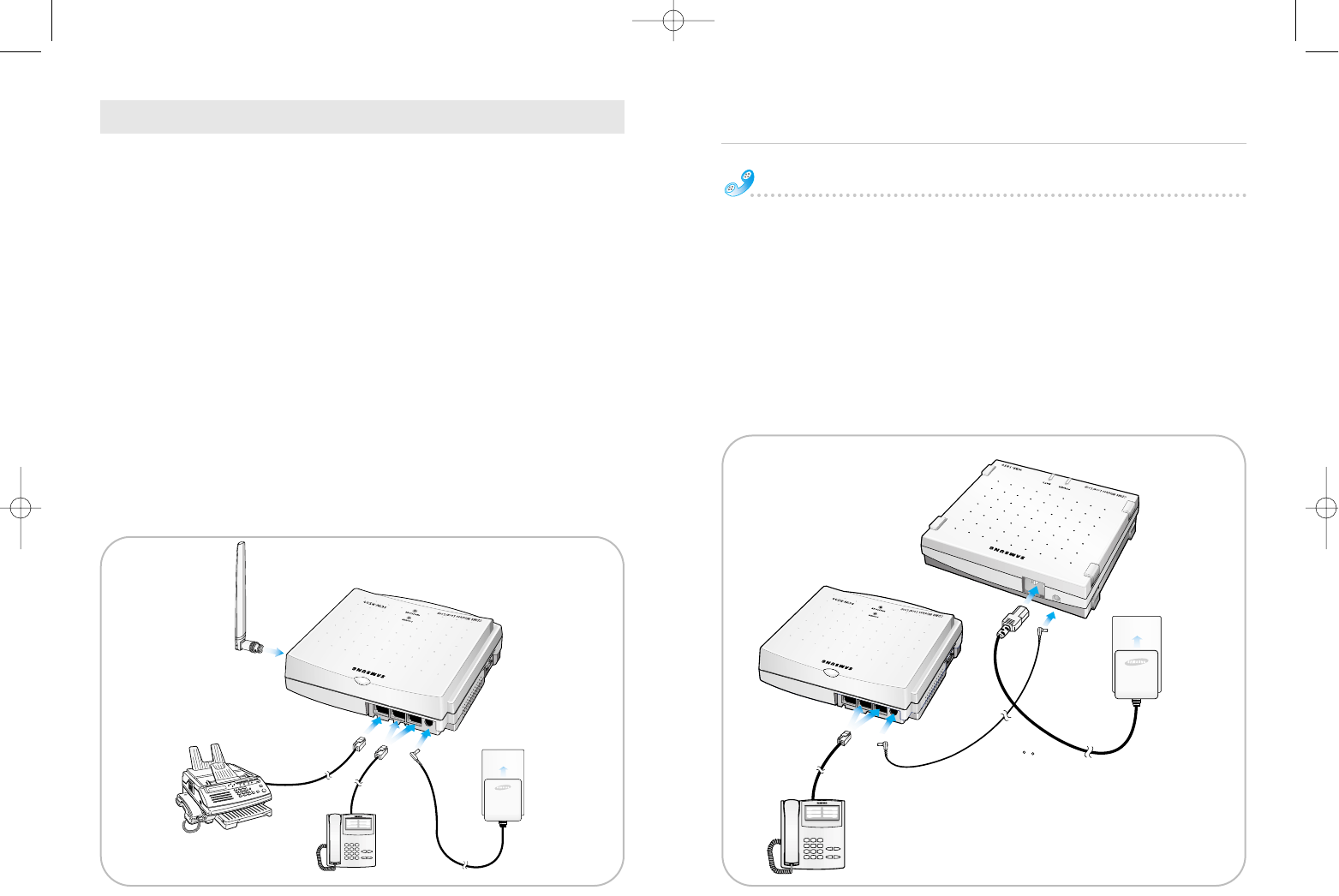
This FWT SCW-R500/R510 operates by receiving electricity from an electrical
outlet or external power supply.
1Connect the terminal mounted Antenna on the side of the terminal.
2Connect a conventional wired telephone to a RJ-11 phone port.
(SCW-R500: 3 RJ-11 phone ports / SCW-R510: 2 RJ-11 phone port)
Use the telephone compatible to FCC part 68 as possible, otherwise it
may not work properly.
FWT works only tone dialing.
3Plug the AC adaptor output into the rear DC 9V jack of the Terminal.
4Plug the AC adaptor plug into an appropriate electrical outlet.
5Connect a G3 analog facsimile machine to a dedicated RJ-11 port.
(only for SCW-R510)
✐ The usage of RS-232C connector on the base of the FWT is not user but
dealer's maintenance.
How to install External Power Supply(option)
1Connect the DC power cable to External power supply.
2Connect the DC power cable to FWT.
3Connect the AC power connector to External power supply.
4Plug the AC power connector to wall outlet.
5Connect a wired telephone to a RJ-11 phone port
Setting up your terminal
SETTING UP YOUR TERMINAL
1
24
53
1
24
5
3
SCW-R500 1/9/99 12:06 PM Page 6
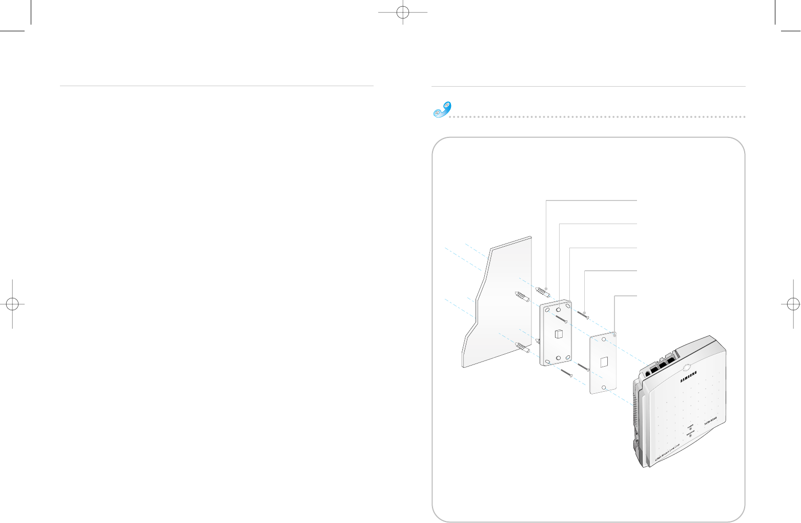
Screws and Caps are provided for mounting the unit on a wall.
Screws and Caps are recommended for most wall surface.
For wooden wall installations, only the screws are required.
1 Mark four mounting hole locations on the wall.
2 Drill four holes at the marked location.
3 If not using Caps, drill four holes in the wood.
If using Caps, drill four holes at the marked location.
Insert the Caps into the holes and tap the Cap heads flush against the wall.
4 Remove wall mountable bracket cover from wall mountable bracket.
5 Attach the wall mountable bracket.
6 Tighten the screws firmly.
7 Put a cover to wall mountable bracket.
8Plug in the RJ-11 Phone Port and Power Connector and route the cords in a
groove.
9Screw the antenna into antenna connector.
10Install the FWT onto the wall mountable bracket hook.
Setting up your terminal
Setting up your terminal
FWT Wall Mount Installation
Wall mounting Caps(4)
Wall mountable bracket
Screws(4)
Wall mountable bracket hook
Wall mountable bracket Cover
Wall
SCW-R500 1/9/99 12:06 PM Page 8
Making Calls
Receiving Calls
Basic Operation
Setting up your terminal
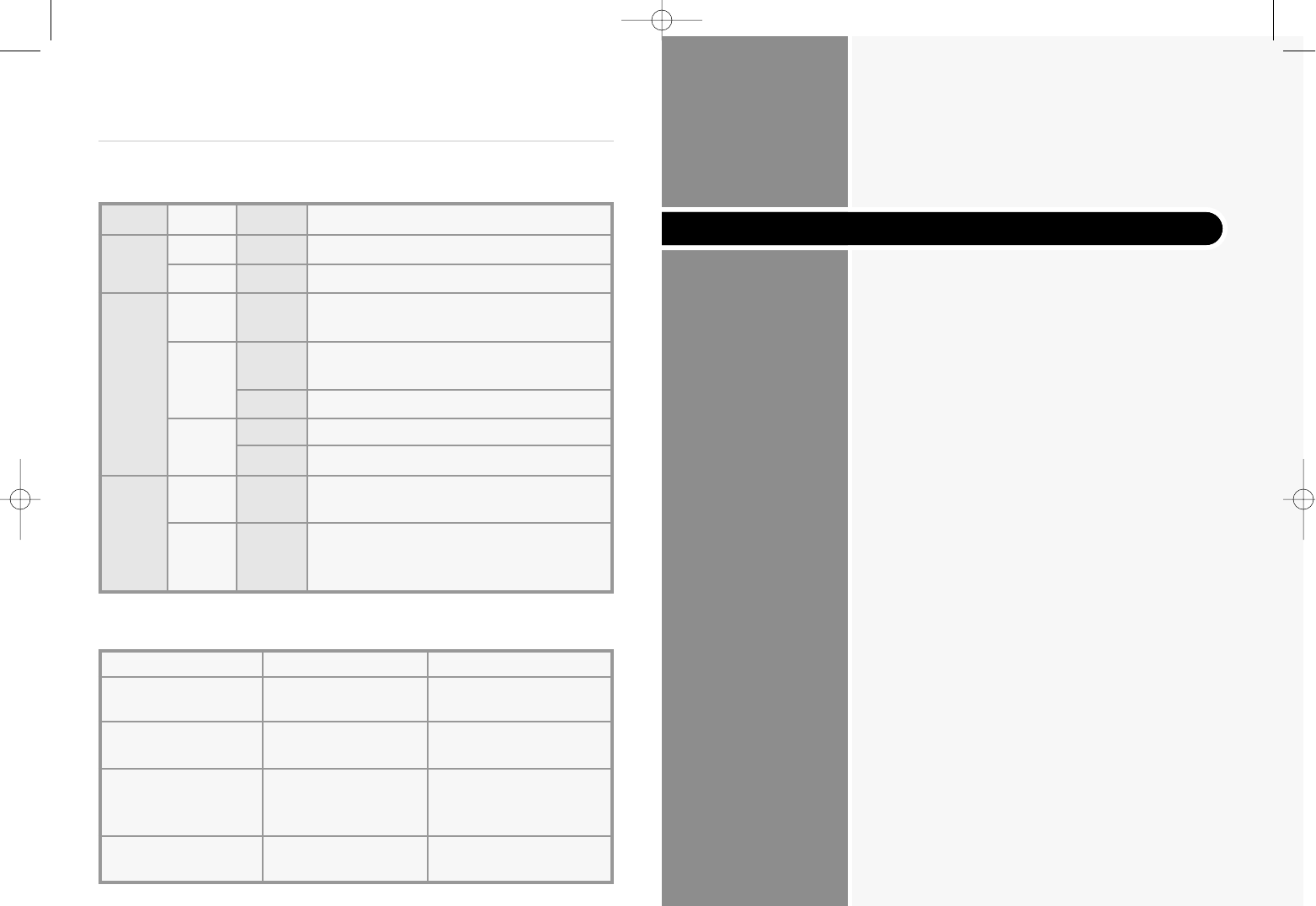
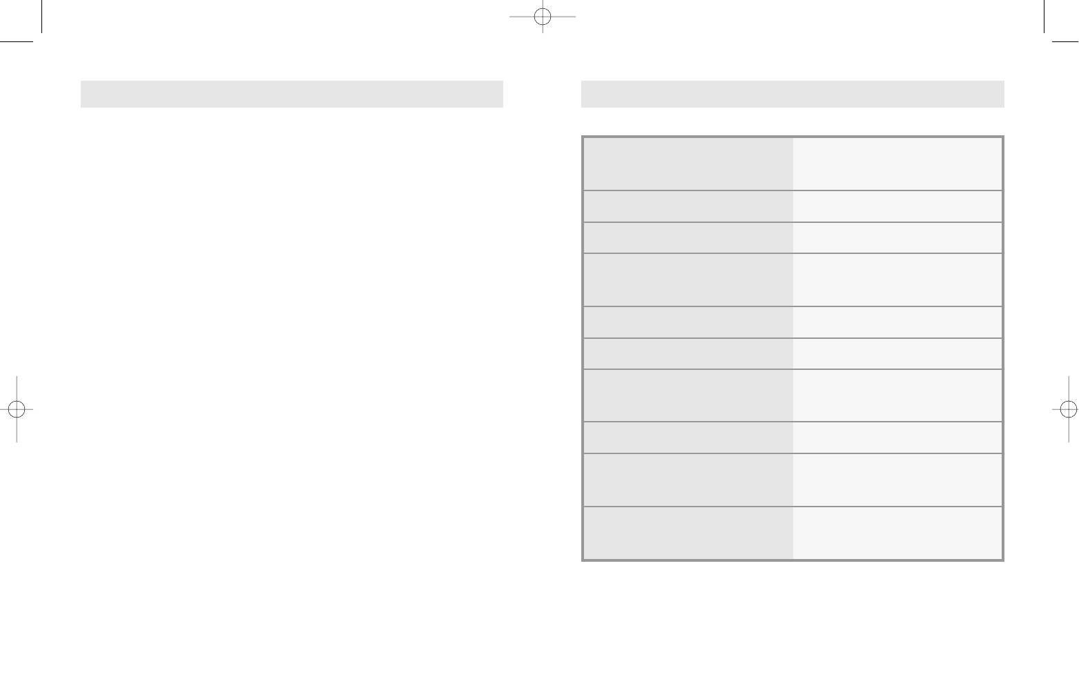
LED indications are described in the following table:
Sound indications are described in following table:
LED Color Condition Meaning
Power – Off No Power is being supplied the terminal.
RED On Normal operation.
RED On No service condition. In this case, contact
your dealer.
RSSI ORANGE On Voice through the line is not clear but a call
is available.
Blinking Incoming call
GREEN On Best service condition.
Blinking Incoming call
–Off Normal operation without any voice mail
Voice message.
Mail You have voice mail message.
GREEN On Contact your service provider to activate
Message Service.
Type
Normal dial tone
No Service tone
Outgoing call
restriction tone
Voice mail tone
Condition
20sec on;
300msec off
1.5sec on;
800 msec off
800 msec on;
200 msec off
three times (100msec
on;100msec off)
Meaning
The FWT is in-service with
adequate receive signal.
FWT is not capable of
making or receiving calls.
FWT is not capable of
making calls but is
capable of receiving calls.
You have voice mail
message.
SCW-R500 1/9/99 12:06 PM Page 10

Adjusting Volume
Terminal Reset
Restricting Use of the Phone
Setting Warning Beeps
Changing the Lock Code
• To disconnect when you’re through, replace the handset.
NOTE: • Be sure the phone’s ringer is enabled.
• If you heard incoming call in picking up the handset, you can receive
the call by pressing any digit key.
1First, check to see that your FWT Phone is turned on.
If the Power LED is lit, that means the power is on.
2Pick up the handset.
●You hear a dial tone.
3Using the number keypad, dial the desired telephone number.
✐ When you finish inputting phone number, you have to press button.
If you don't press button, A call is not connected.
4When the other person answers, begin your conversation.
5To end the call, replace the handset.
NOTE: • You can dial by 32 digit including .
• You can dial emergency call by pressing and holding without
inputting any digits.
You can't change the emergency call number.
MAKING CALLS
The terminal signals the telephone(s) to ring when an incoming call is
detected. Pick up the telephone handset and begin talking into the
microphone on the handset.
RECEIVING CALLS
Advanced Feature
SCW-R500 1/9/99 12:06 PM Page 12
um-
0
OPER
9
WXYZ
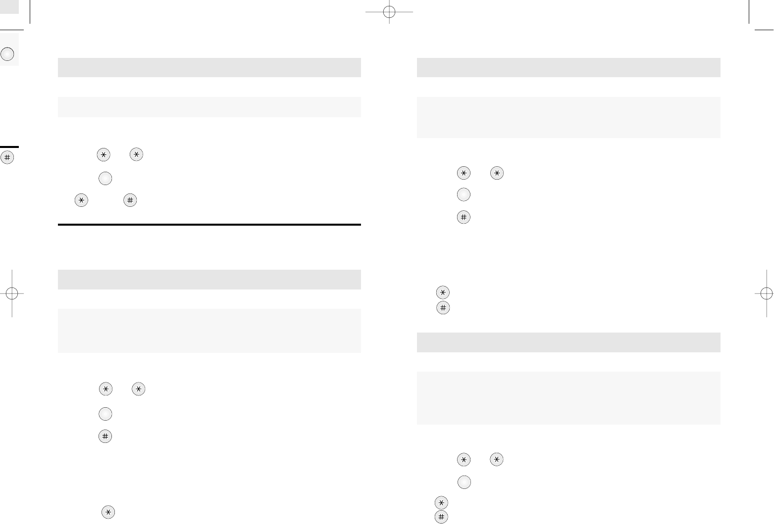
1Pick up the handset.
2Press and .
3Press .
4Press .
5Enter 4 digits Lock Code Number.
(The default lock code is preset to 0000 at the factory.)
NOTE: If the code is correct, it sounds confirmation beep.
If not, it returns to the stand by mode with error beep.
6set outgoing call restrict.
release outgoing call restrict.
1Pick up the handset.
2Press and .
3Press .
4(up) or (down).
NOTE: This feature is automatically set after 3 seconds.
You will hear confirmation beep.
1Pick up the handset.
2Press and .
3Press .
4set 1-Minute Alert.
cancel 1-Minute Alert.
RESTRICTING USE OF THE PHONE
1Pick up the handset.
2Press and .
3Press .
4Press .
5Enter 4 digits Lock Code Number.
(The default lock code is preset to 0000 at the factory.)
NOTE : If the code is correct, it sounds confirmation beep.
If not, it returns to the stand by mode with error beep.
6Press .
ADJUSTING VOLUME
TERMINAL RESET
You can control the sound volume on your phone. Used when you wish to block outgoing calls from being made, but still
wish to receive incoming calls at any time. This feature can be disabled
and enabled through simple keypad number code entry.
Resets the terminal back to the initial service status of factory
pre-programmed state. This feature can be disabled and enabled through
simple keypad number code entry.
5
JKL
4
GHI
3
DEF
SETTING WARNING BEEPS
A discrete tone is generated after each minute interval into the call
conversation to notify you that a minute has passed since the beginning of
the call or after the previous time of discrete tone,
regardless of when you make or receive a call.
1
SCW-R500 1/9/99 12:06 PM Page 14
• Call Waiting
• Three-Way Calling
• Call Forwarding
• Caller ID
• Voice Mail Service
1Pick up the handset.
2Press and .
3Press .
4Press .
5Enter 4 digits Lock Code Number.
(The default lock code is preset to 0000 at the factory.)
NOTE: If the code is correct, it sounds confirmation beep.
If the code is incorrect, it returns to the standby mode with error
beep.
6Enter 4 digits new Lock Code Number.
It sounds confirmation beep.
7Enter 4 digits new Lock Code Number again.
If it is different from the new Lock code you entered in the beginning, it
returns to the standby mode with error beep.
8Press to store new Lock Code.
If you press another key, it returns to the standby mode with error beep.
NOTE: If it is correct, it sounds confirmation beep.
CHANGING THE LOCK CODE
Used when you wish to change the lock code of the terminal.
The programmed lock code prevents the terminal from being operational
to any other people without your permission. This feature can be disabled
and enabled through simple keypad number code entry.
When you first buy the phone, the lock number is 0000.
2
ABC
Optional Features
SCW-R500 1/9/99 12:06 PM Page 16
Call Waiting
Call Waiting is a feature which enables you to be alerted to a second
incoming call while you are on the first call of your telephone. You have
the option of responding to the second call while putting the first call on
hold or you can disable the Call Waiting option during a particular call.
Contact your service provider to activate or deactivate Call Waiting.
Three-Way Calling
Three-Way Calling is a feature that enables you to set up a three-way
conversation with two other different-numbered users.
Contact your service provider to activate or deactivate Three-Way Calling.
Call Forwarding
Call Forwarding is a feature that enables you to forward all your incom-
ing calls to another phone number, even if your telephone is turned off.
You can still make calls from your telephone even when Call Forwarding
is activated. Contact your service provider to activate or deactivate Call
Forwarding.
Caller ID
Caller ID is a feature which notifies you who is calling by displaying the
caller's number on the telephone's LCD when an incoming call come
through with a ring. This feature is available only with a telephone that
has an LCD display on it. Contact your service provider to activate or
deactivate Caller ID.
Voice Mail Service
Voice Mail Service is a feature that allows the terminal to receive voice
mail and forward it to your telephone when you press a certain
sequence of keypad number. Contact your service provider to activate
or deactivate Voice Mail Service.
OPTIONAL FEATURES
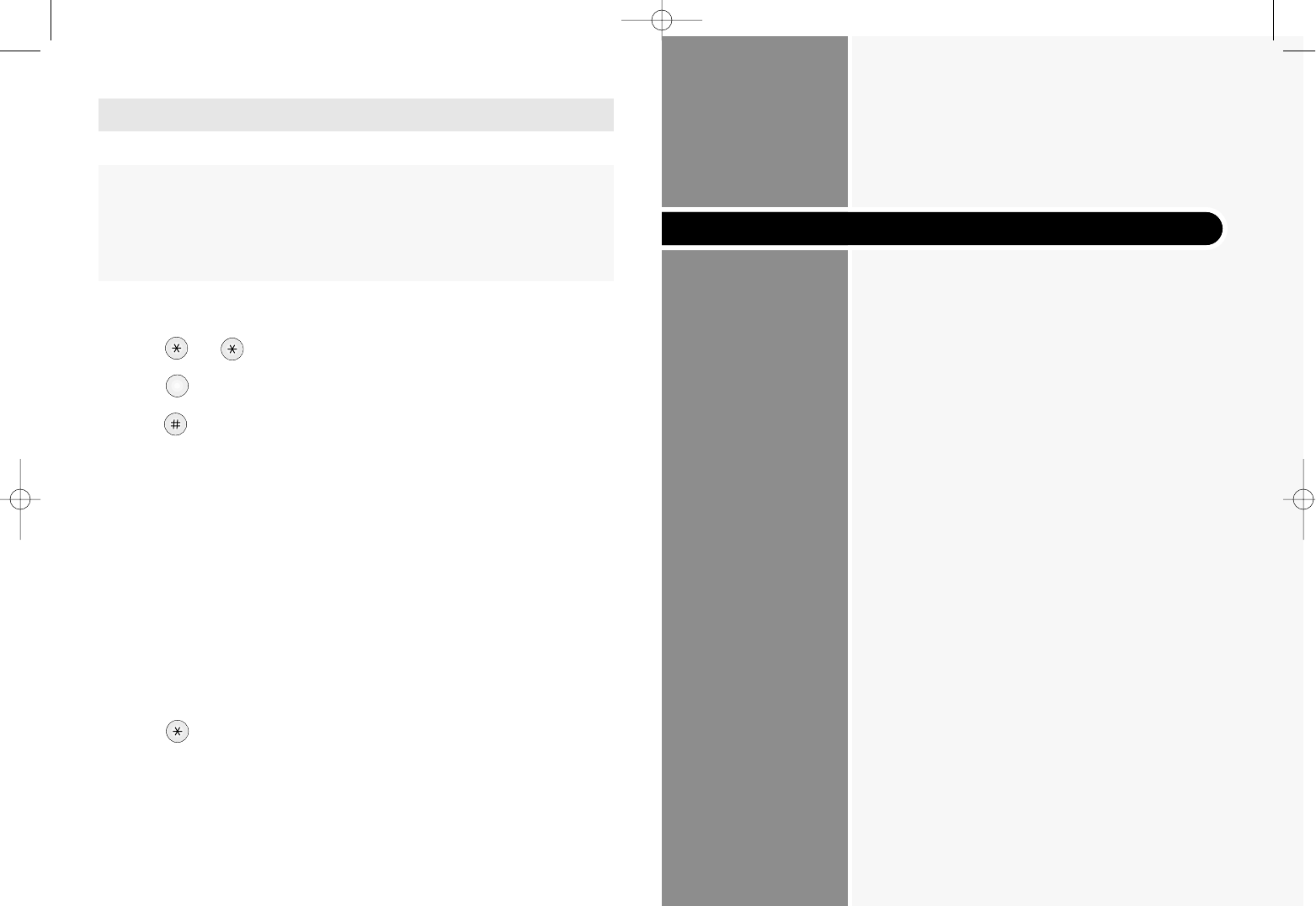
Menu Options Table
Troubleshooting
Specifications
Miscellaneous
SCW-R500 1/9/99 12:06 PM Page 18
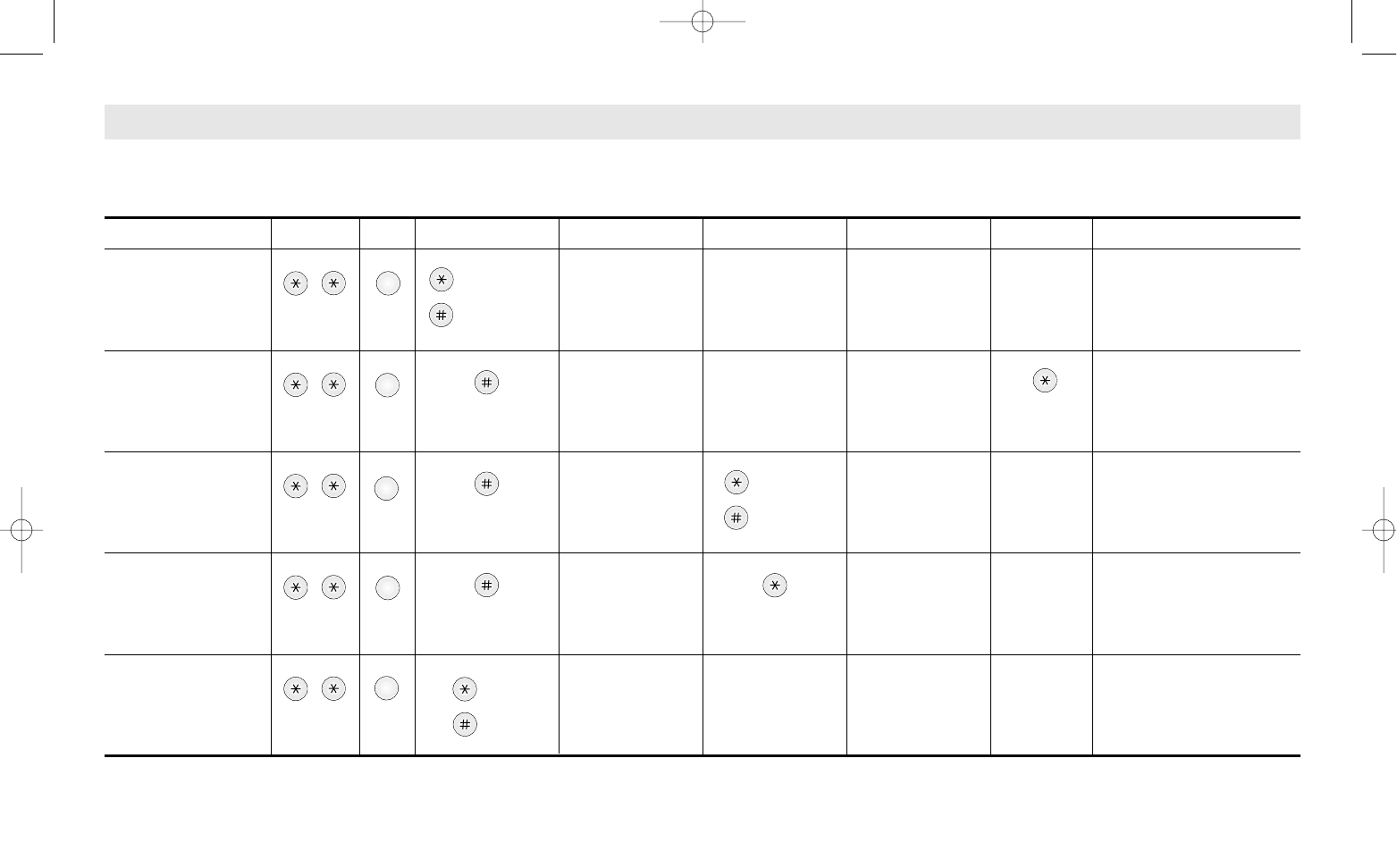
Set
release
New lock
code
4 digits input
New lock
code
4 digits input
Decides whether alert
beep should sound at one
minute intervals when you
make or receive a call.
Used when you change
the lock code of the
phone.
Used when you limit use of
the outgoing calls.
Return phone to factory
settings.
Adjusts the Volume of
phone.
MENU OPTIONS TABLE
* The lock code is preset to 0000 at the factory.
I II III IV V VI VII
Explanation
2
ABC
3
DEF
4
GHI
5
JKL
1
1. Setting
warning beeps
2. Changing the
lock code
3. Restricting
outgoing call
4. Terminal Reset
5. Adjusting
Volume
Set
release
Lock code
4 digits input
Lock code
4 digits input
Lock code
4 digits input
Wait
3 seconds
up
down
,
,
,
,
,
SCW-R500 1/9/99 12:06 PM Page 20
TROUBLESHOOTING
•Troubleshoot the conventional wired telephone
In the event you are unable to place or receive telephone calls, first be sure
that the connetion wire is properly connected to the RJ-11 phone port on the
terminal and to the RJ-11 port of the telephone. If unsure whether or not the
telephone is operational, connect a telephone which is known to be
operational to the terminal.
If service is available with the operational telephone, replace or repair your
telephone equipment. If service is still not available, then follow instructions
under "Troubleshoot the Fixed Wireless Terminal".
•Troubleshoot the Fixed Wireless Terminal
Check for the appropriate power indication on the LED. If no power, check
the Adaptor(or External Power Supply)connection between the electrical
outlet and the terminal. Check for the appropriate Received Signal Strength
Indication(RSSI), Power, and Message Indication through the designated
LED, respectively.
SPECIFICATIONS
Frequency Range Tx : 825-849 MHz
Rx : 870-894 MHz
Channel Bandwith CDMA 1.25 MHz
Multi Connection Supports 5 REN
RJ-11 Phone Port SCW-R500 : 3
SCW-R510 : 2
RJ-11 Analog Fax Port SCW-R510 : 1
Power Supply DC 9V 1.2A
Temperature of operation -20°C~ +50°C
Relative humidity 5% ~ +95%
Temperature of storage -25°C ~ +75°C
Dimension 200x170x48.5 (mm)
7.9x6.7x1.9 (in.)
Weight 495g / 1.1 lb.
(without external adaptor)
SCW-R500 1/9/99 12:06 PM Page 22