Samsung Electronics Co SFG-AA100DC 5G Access Unit User Manual Installation Manual
Samsung Electronics Co Ltd 5G Access Unit Installation Manual
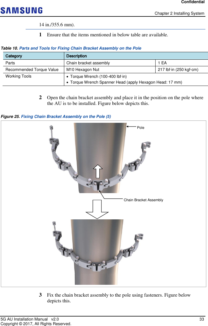
UserManual.wiki
>
Samsung Electronics Co
>
SFG AA100DC User Manual
Installation Manual
Navigation menu
Upload a User Manual
Namespaces
Wiki Guide
HTML
PDF
Info
Views
User Manual
Discussion / Help
Navigation
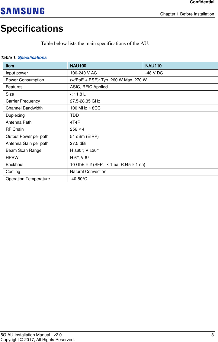
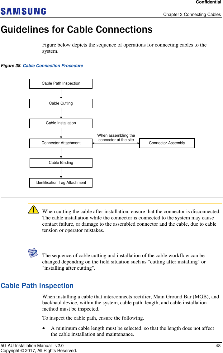
![Confidential 5G AU Installation Manual v2.0 1 Copyright © 2017, All Rights Reserved. Chapter 1 Before Installation This chapter introduces Access Unit (AU) and describes the items that you should know before installation. System View and External Interface This section provides the pictorial view of the AU and its interfaces. AU View Figure below depicts the physical structure of the AU. Figure 1. AU View [Bottom View] [Top View] [Left View] 15.6 (396) 6 (152) Unit: in. (mm) [Right View] [Rear View] [Front View] 9.2 (233)](https://usermanual.wiki/Samsung-Electronics-Co/SFG-AA100DC/User-Guide-3754736-Page-15.png)
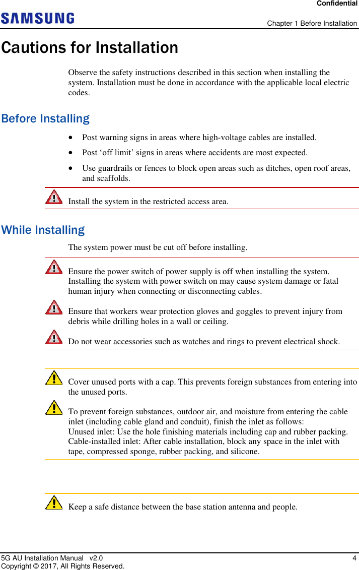
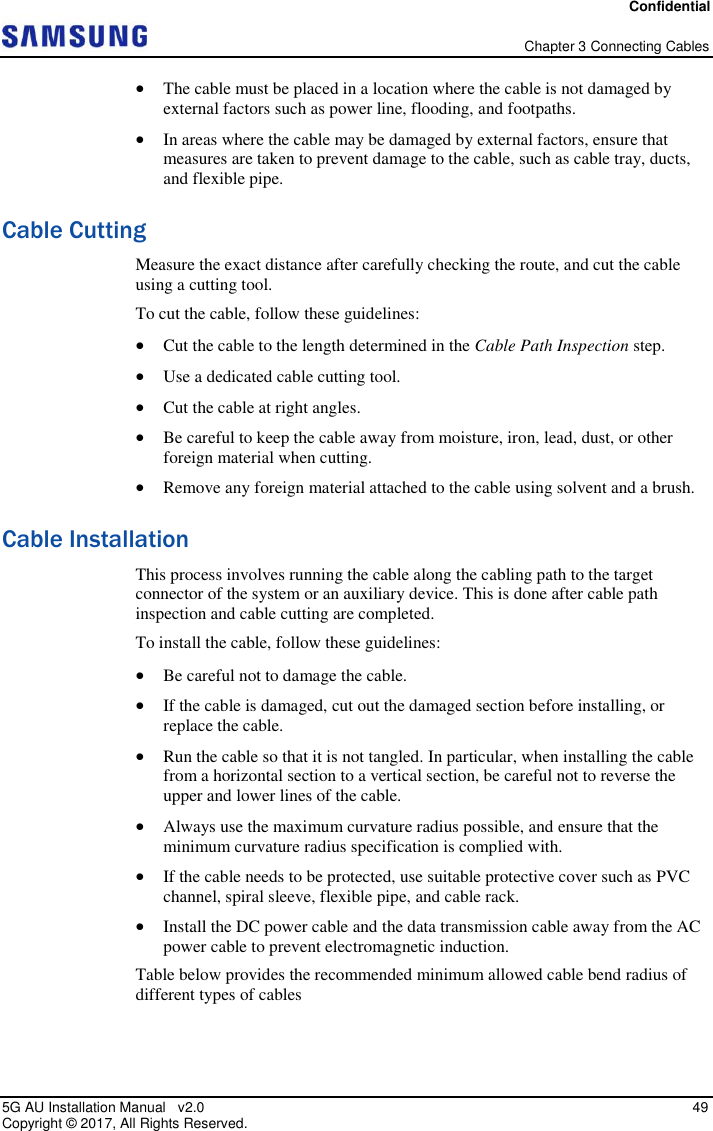
![Confidential Chapter 1 Before Installation 5G AU Installation Manual v2.0 2 Copyright © 2017, All Rights Reserved. AU External Interface Figure below depicts the external interface structure of the AU. Figure 2. AU External Interface [Bottom View_AC Type] [Top View] GNSS UDA Ground Terminal BH0 CLK BH1 PWR [Bottom View_DC Type] UDA BH0 CLK BH1 Ground Terminal PWR [AC PWR Connector] [DC PWR Connector]](https://usermanual.wiki/Samsung-Electronics-Co/SFG-AA100DC/User-Guide-3754736-Page-16.png)
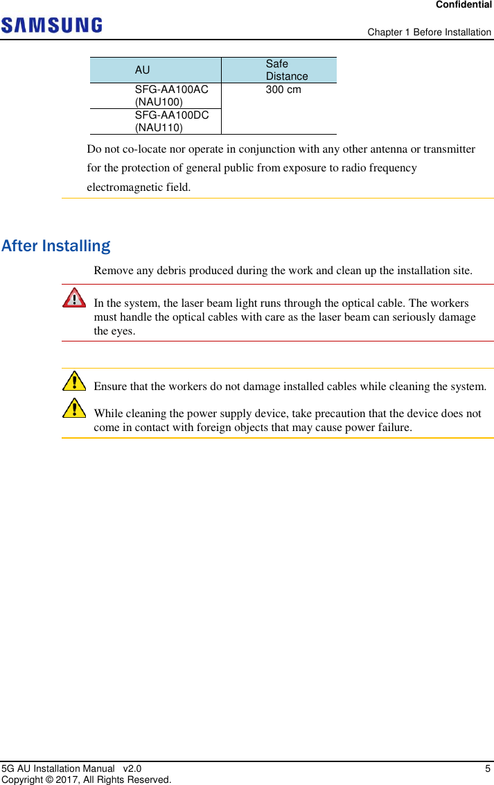
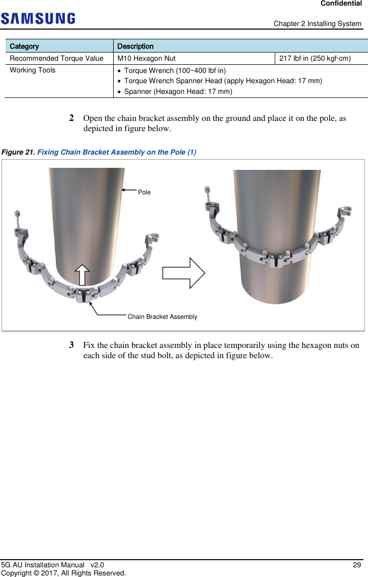
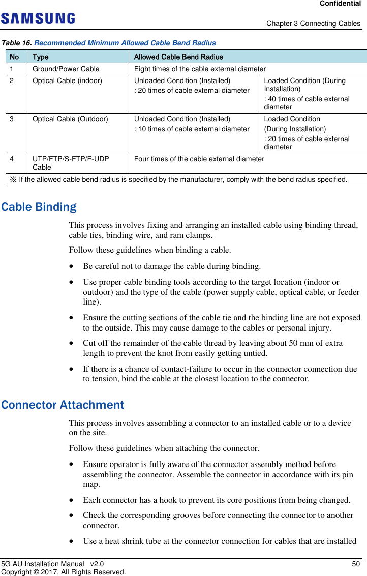
![Confidential Chapter 2 Installing System 5G AU Installation Manual v2.0 10 Copyright © 2017, All Rights Reserved. System Arrangement A minimum distance must be secured around the AU, in each direction for installation and maintenance. Figure below depicts the minimum distance that must be secured for pole type installation of the AU using mounting bracket. Figure 4. AU Arrangement Pole type Installation (Using Mounting Bracket) Figure below depicts the minimum distance that must be secured for pole type installation of the AU using chain bracket assembly. Unit: in. (mm) [Top View] [Front View] ≥ 16 (400) ≥ 8 (200) ≥ 8 (200) W: 9.1 (231) H: 18.5 (470) 7.7 (194) ≥ 32 (800) ≥ 16 (400)](https://usermanual.wiki/Samsung-Electronics-Co/SFG-AA100DC/User-Guide-3754736-Page-24.png)
![Confidential Chapter 2 Installing System 5G AU Installation Manual v2.0 11 Copyright © 2017, All Rights Reserved. Figure 5. AU Arrangement Pole Type Installation (Using Chain Bracket Assembly) Figure below depicts the minimum distance that must be secured for wall type installation of the AU using mounting bracket. Figure 6. AU Arrangement Wall type Installation (Using Mounting Bracket) 9 (226) Unit: in. (mm) [Top View] [Front View] ≥ 8 (200) ≥ 8 (200) W: 9.1 (231) H: 18.5 (470) ≥ 32 (800) ≥ 16 (400) ≥ 32 (800) ≥ 16 (400) Unit: in. (mm) [Top View] [Front View] ≥ 16 (400) ≥ 8 (200) ≥ 8 (200) W: 9.1 (231) H: 18.5 (470) 7.7 (194) ≥ 32 (800) ≥ 16 (400)](https://usermanual.wiki/Samsung-Electronics-Co/SFG-AA100DC/User-Guide-3754736-Page-25.png)

![Confidential Chapter 2 Installing System 5G AU Installation Manual v2.0 19 Copyright © 2017, All Rights Reserved. Table 7. Parts and Tools for Fixing AU on the Pole Category Description Parts Fasteners M6 × L23 SEMS (Hexagon +) (Fastened to the unit bracket) 1 EA Recommended Torque Value M6 SEMS 43 lbfin (50 kgf·cm) Working Tools Screw Driver Bit ('+', Number 3) Torque Driver (20-90 lbf·in) Torque Wrench (10-50 lbfin) Torque Wrench Spanner Head (apply Hexagon Head: 10 mm) 2 Pull out the fastening materials so that they do not jut out from the fixing groove of the unit bracket. (Do not pull out completely.) This is depicted in figure below. Figure 13. Fixing AU on the Pole Mounting Bracket (1) 3 Place the unit bracket on the fixing grooves of the mounting bracket and push the unit bracket down to fix the AU in place. Figure below depicts this. [Top View] M6 SEMS (Hexagon +) [Top View] M6 SEMS (Hexagon +)](https://usermanual.wiki/Samsung-Electronics-Co/SFG-AA100DC/User-Guide-3754736-Page-33.png)
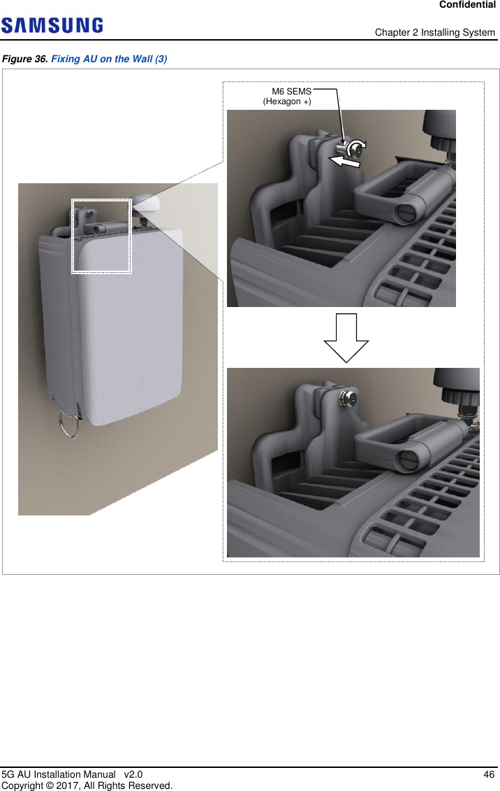
![Confidential Chapter 2 Installing System 5G AU Installation Manual v2.0 20 Copyright © 2017, All Rights Reserved. Figure 14. Fixing AU on the Pole Mounting Bracket (2) 4 Fix the unit bracket to the mounting bracket using fasteners as shown in figure below. Mounting Bracket Unit Bracket [Top View]](https://usermanual.wiki/Samsung-Electronics-Co/SFG-AA100DC/User-Guide-3754736-Page-34.png)
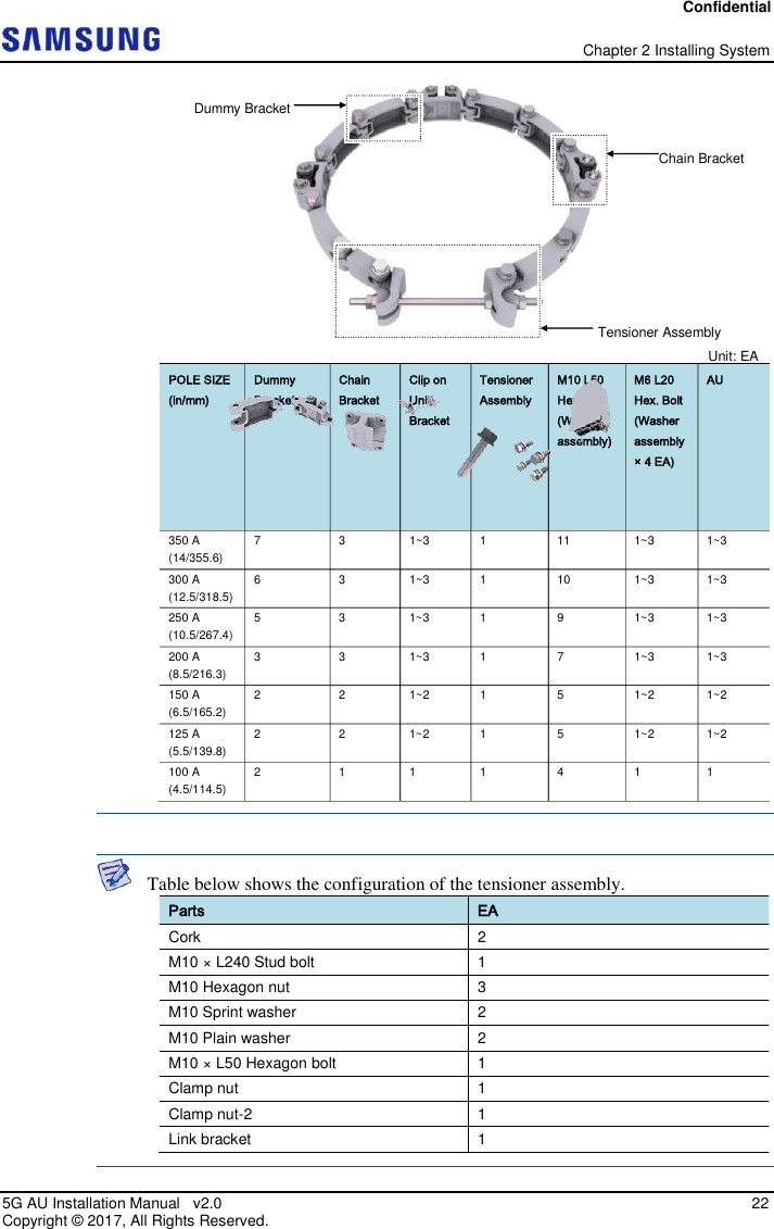
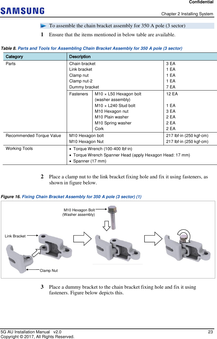
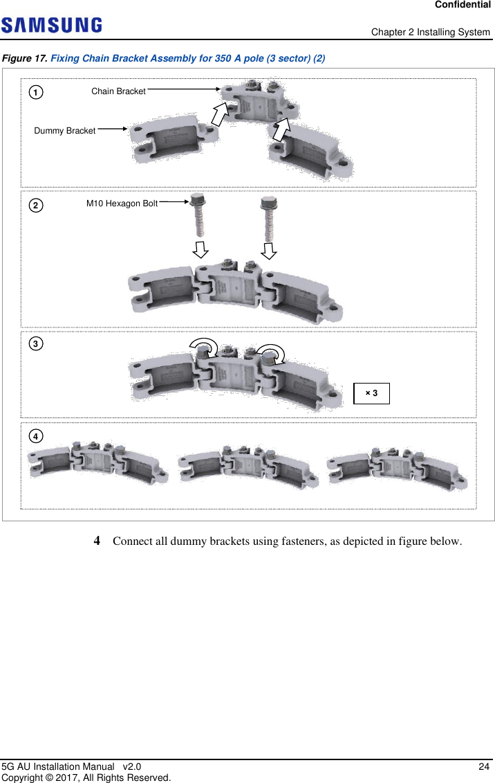
![Confidential Chapter 2 Installing System 5G AU Installation Manual v2.0 21 Copyright © 2017, All Rights Reserved. Figure 15. Fixing AU on the Pole Mounting Bracket (3) Using Chain Bracket Assembly To fix Chain Bracket Assembly on the Pole The standard of the pole on which an AU can be attached using a chain bracket assembly is 100 A [Outer Diameter (OD): 4.5 in./114.5 mm]-350 A (OD: 14 in./355.6 mm). The number of AUs (1-3 sector) and the chain bracket assemblies that can be installed depends on the diameter of the pole. (See table below) M6 SEMS (Hexagon +)](https://usermanual.wiki/Samsung-Electronics-Co/SFG-AA100DC/User-Guide-3754736-Page-35.png)
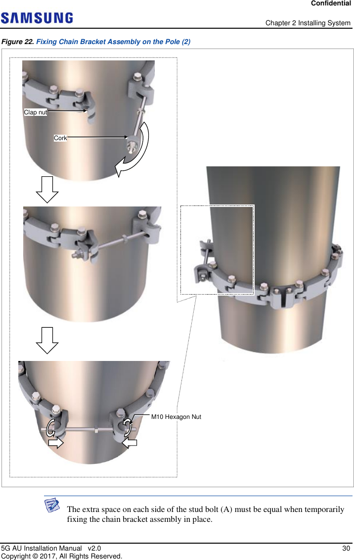
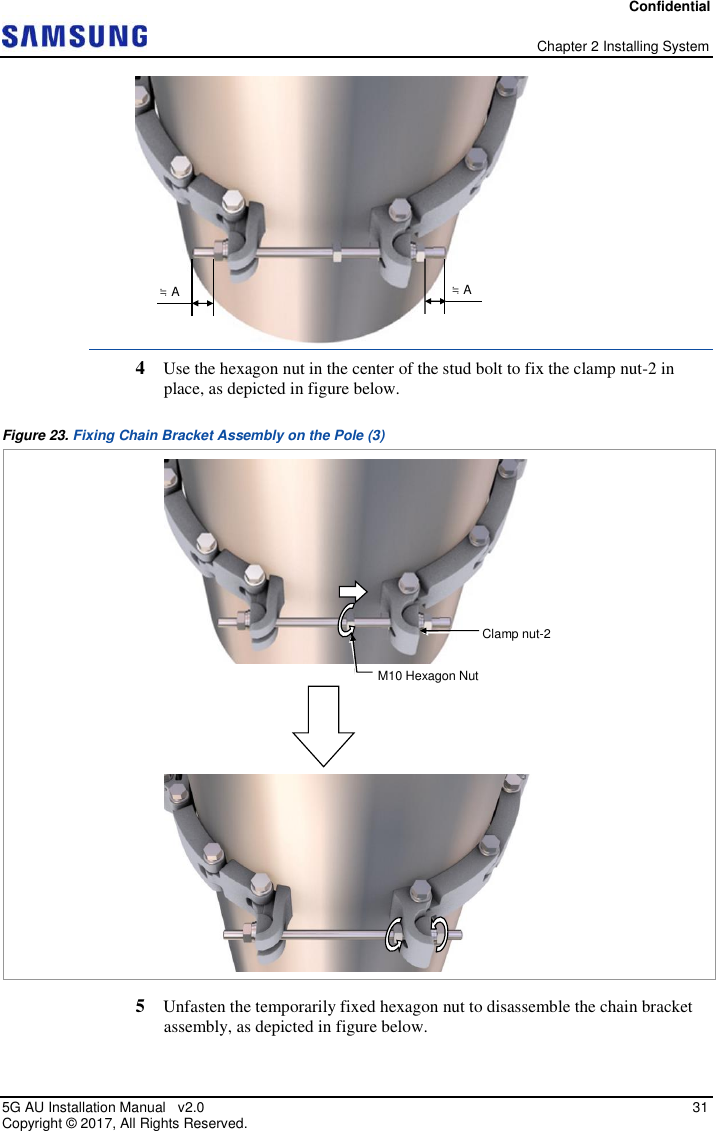
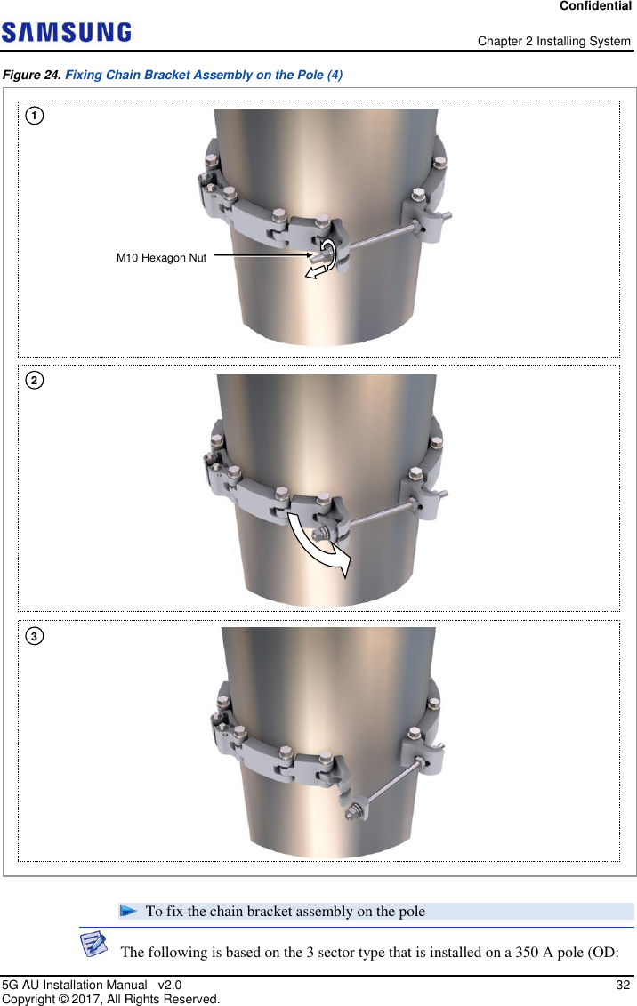
![Confidential Chapter 2 Installing System 5G AU Installation Manual v2.0 35 Copyright © 2017, All Rights Reserved. 4 Check the level of chain bracket assembly on a pole and adjust the level as detailed in figure below. Figure 27. Fixing Chain Bracket Assembly on the Pole (7) When fixing the chain bracket assembly on a pole, be sure to check the level of bracket. After finishing the installation, adjust the level minutely. When poor leveling happens, adjust the position of fasteners used to fix the chain bracket assembly. After the chain bracket assembly is fixed, the extra space on each side of the stud [1 Sector] [2 Sector] If it is level, the bubble of the spirit level is positioned at the center of both lines.](https://usermanual.wiki/Samsung-Electronics-Co/SFG-AA100DC/User-Guide-3754736-Page-49.png)
![Confidential Chapter 2 Installing System 5G AU Installation Manual v2.0 37 Copyright © 2017, All Rights Reserved. Figure 28. Fixing AU on the Pole Chain Bracket Assembly (1) 2 Fix all AUs using the same method, as shown in figure below. Chain Bracket fixing hole Clip on Unit Bracket [Top View] [Top View]](https://usermanual.wiki/Samsung-Electronics-Co/SFG-AA100DC/User-Guide-3754736-Page-51.png)
![Confidential Chapter 2 Installing System 5G AU Installation Manual v2.0 39 Copyright © 2017, All Rights Reserved. Wall Type An AU can be fixed on wall using a mounting bracket. This section details the procedures for fixing the mounting bracket on the wall and fixing the AU on the bracket. Marking and Drilling for Wall Mounting To mark on the wall 1 Ensure that the items mentioned in below table are available. Table 11. Tools for Marking Category Description Working Tools Tape Measure Permanent Maker Level Perform leveling test before drilling by referring to System Leveling, to ensure the positions marked are horizontal or vertical. If the result shows the marked positions are not horizontal or vertical, modify the marking positions. When the position to place the system is determined, place the system on that position and then mark the positions where anchor bolts are to be fixed. This reduces marking error range. 2 Check the distance between the location for fixing the AU and the anchor bolt hole, as shown in figure below. [1 sector] [2 sector]](https://usermanual.wiki/Samsung-Electronics-Co/SFG-AA100DC/User-Guide-3754736-Page-53.png)
![Confidential Chapter 2 Installing System 5G AU Installation Manual v2.0 40 Copyright © 2017, All Rights Reserved. Figure 30. AU Marking Dimensions for Wall Type 3 Place the mounting bracket on the fixing location, check the level status using a level, and adjust the level of the bracket assembly. 4 If the level status is normal, mark the anchor bolt holes on the wall. This is detailed in figure below. Figure 31. Marking Wall Type Unit: in. (mm) : Anchor Bolt Hole [Rear View] 3.5 (90) 3.5 (90) Unit: in. (mm)/ Marking Point If it is level, the bubble of the spirit level is positioned at the center of both lines.](https://usermanual.wiki/Samsung-Electronics-Co/SFG-AA100DC/User-Guide-3754736-Page-54.png)
![Confidential Chapter 2 Installing System 5G AU Installation Manual v2.0 41 Copyright © 2017, All Rights Reserved. To drill the anchor holes and fix the anchors 1 Ensure that the items mentioned in below table are available. Table 12. Parts and Tools for Drilling and Anchoring Category Description Parts M8 Set Anchor Assembly 2 EA Woking Tools Hammer Drill Concrete Drill Bit (12 mm) Vacuum Cleaner Hammer Anchor Punch (For M8 Set Anchor) Table 13. Anchor Bolt Drill Bits and Hole Depth Category Anchor Bolt Drill Bits Hole Depth AU M8 12 mm (0.5 in.) 38 mm (1.5 in.) 2 Drill anchor holes at the marked points. Remove dust from the holes using a vacuum cleaner. Fix set anchor to the drilled hole. This is shown in figure below. (Ensure you do not lose the M8 hexagon nut, spring washer, and plain washer.) Figure 32. Drilling and Anchoring [O] * Remove the debris from the drilled hole. [Anchor Hole Cross Section] 38 mm (1.5 in) [X] 12 mm. (0.5 in.) 12 mm (0.5 in.) M8 Anchor Bolt Anchor Punch Hammer Vacuum Cleaner Hammer Drill](https://usermanual.wiki/Samsung-Electronics-Co/SFG-AA100DC/User-Guide-3754736-Page-55.png)
![Confidential Chapter 2 Installing System 5G AU Installation Manual v2.0 44 Copyright © 2017, All Rights Reserved. Figure 34. Fixing AU on the Wall (1) 3 Place the unit bracket on the fixing grooves of the mounting bracket and push the unit bracket down to fix the AU in place. Figure below depicts this. [Top View] M6 SEMS (Hexagon +) [Top View] M6 SEMS (Hexagon +)](https://usermanual.wiki/Samsung-Electronics-Co/SFG-AA100DC/User-Guide-3754736-Page-58.png)
![Confidential Chapter 2 Installing System 5G AU Installation Manual v2.0 45 Copyright © 2017, All Rights Reserved. Figure 35. Fixing AU on the Wall (2) 4 Fix the unit bracket to the mounting bracket using fasteners as shown in figure below. Mounting Bracket Unit Bracket [Top View]](https://usermanual.wiki/Samsung-Electronics-Co/SFG-AA100DC/User-Guide-3754736-Page-59.png)
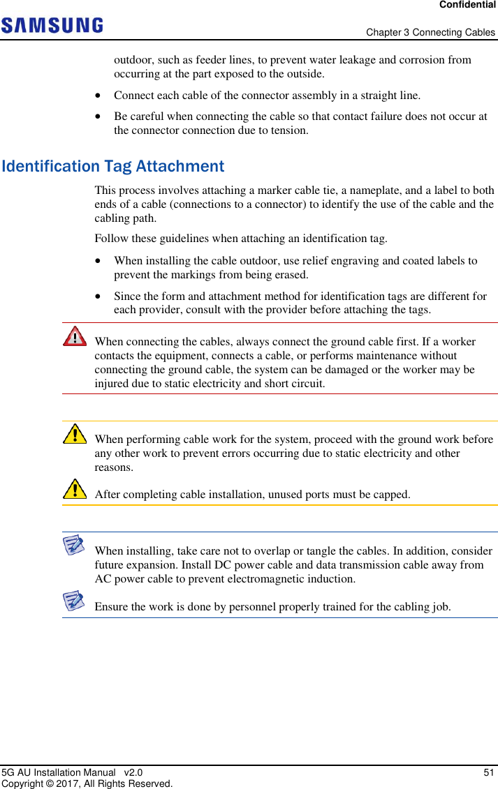
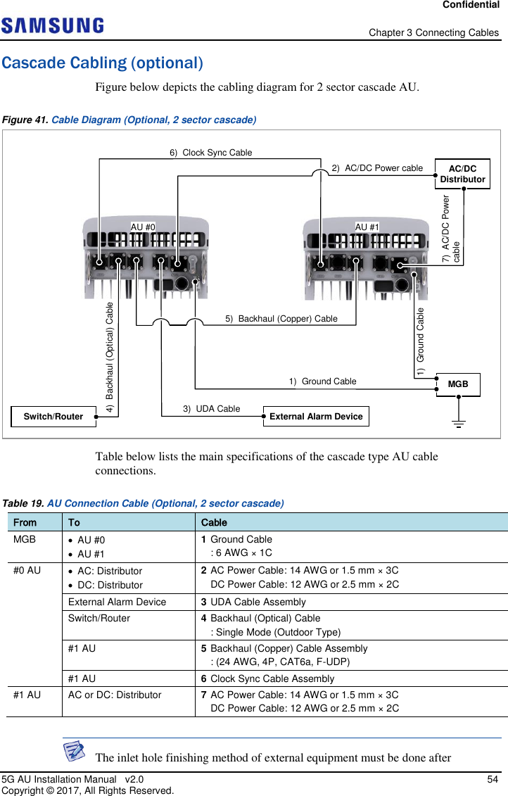
![Confidential Chapter 3 Connecting Cables 5G AU Installation Manual v2.0 52 Copyright © 2017, All Rights Reserved. Cabling Diagram This section describes the different cabling options for the AU. For AC Type Figure below depicts the cabling diagram of AC type AU. Figure 39. Cable Diagram-AC Type Table below lists the main specifications of the AC type AU cable connections. Table 17. AU Connection Cable_AC Type From To Cable MGB AU 1 Ground Cable : 6 AWG × 1C AU AC: Distributor 2 AC Power Cable: 14 AWG or 1.5 mm2 × 3C Switch 3 Backhaul (Optical) Cable : Single Mode (Outdoor Type) 4 Backhaul (Copper) Cable Assembly : (24 AWG, 4P, CAT6a, F-UDP) External Alarm Device 5 UDA Cable : UDA Cable Assembly The inlet hole finishing method of external equipment must be done after CLK BH0 BH1 UDA PWR AC Distributor Switch/Router MGB 4) Backhaul (Optical) Cable 5) Backhaul (Copper) Cable 1) Ground Cable 2) AC Power cable 3) UDA Cable External Alarm Device [Bottom View]](https://usermanual.wiki/Samsung-Electronics-Co/SFG-AA100DC/User-Guide-3754736-Page-66.png)
![Confidential Chapter 3 Connecting Cables 5G AU Installation Manual v2.0 53 Copyright © 2017, All Rights Reserved. consultation with operation company, if the cable is connected to external equipment such as optical distribution box. - The cables: Power cable, Backhaul (Optical and Copper) cables, and UDA cable For DC Type Figure below depicts the cabling diagram of DC type AU. Figure 40. Cable Diagram-DC Type Table below lists the main specifications of the DC type AU cable connections. Table 18. AU Connection Cable_DC Type From To Cable MGB AU 1 Ground Cable : 6 AWG × 1C AU DC: Distributor 2 DC Power Cable: 12 AWG or 2.5 mm2 × 2C Switch 3 Backhaul (Optical) Cable : Single Mode (Outdoor Type) 4 Backhaul (Copper) Cable Assembly : (24 AWG, 4P, CAT6a, F-UDP) External Alarm Device 5 UDA Cable : UDA Cable Assembly The inlet hole finishing method of external equipment must be done after consultation with operation company, if the cable is connected to external equipment, such as optical distribution box. - Cables: Power cable, Backhaul (Optical and Copper) cables, and UDA cable For the DC type, all cable connections except the power cable are identical to the AC type. CLK BH0 BH1 UDA PWR 1) DC Power cable [Bottom View] DC Distributor](https://usermanual.wiki/Samsung-Electronics-Co/SFG-AA100DC/User-Guide-3754736-Page-67.png)
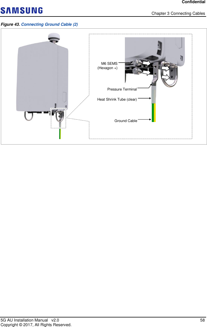
![Confidential Chapter 3 Connecting Cables 5G AU Installation Manual v2.0 57 Copyright © 2017, All Rights Reserved. Category Description Working Tools Cable Cutter Wire Stripper Crimping tool Heating Gun Nipper Screw Driver (‘+’, Number 3) Torque Driver (20-90 lbf·in.) Screw Driver Bit (‘+’, Number 3) For the pressure terminals of the cable, the UL Listed products or equivalent must be used. Example: Manufacturer-Panduit AU: 6 AWG Pressure Terminal (LCD6-14A-L) 2 Install the ground cable from the MGB to the AU ground terminal as shown in figure below. Figure 42. Connecting Ground Cable (1) 3 Assemble a pressure terminal and a heat shrink tube at the end of the AU ground cable. 4 Align the pressure terminal to the mounting hole of the AU ground terminal. 5 Firmly fix the pressure terminal onto the AU ground terminal using fasteners. Figure below depicts the steps 3 to 5. [Bottom View] MGB Ground Cable](https://usermanual.wiki/Samsung-Electronics-Co/SFG-AA100DC/User-Guide-3754736-Page-71.png)
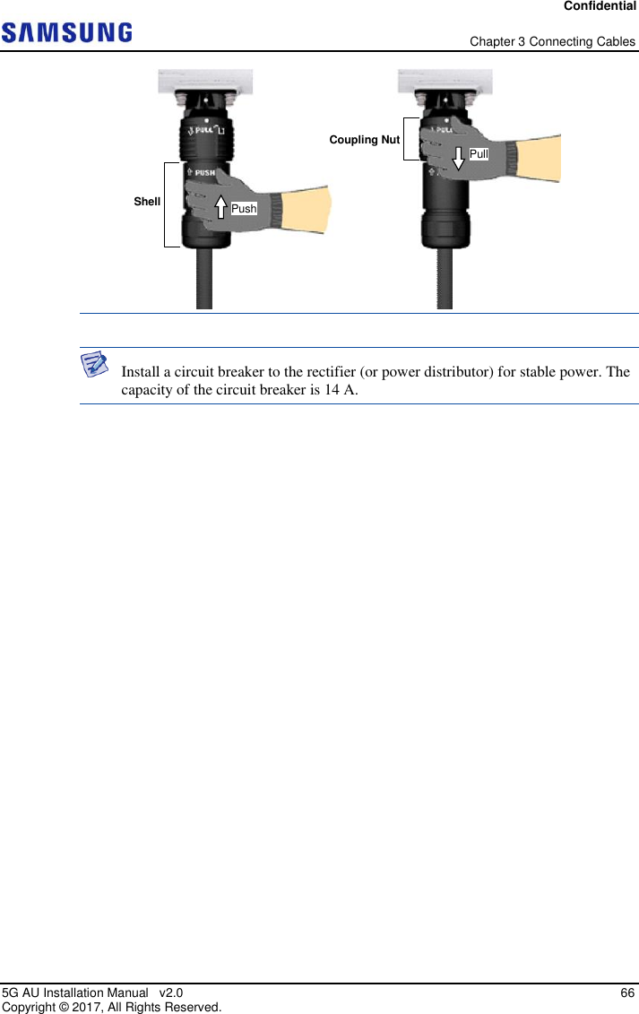
![Confidential Chapter 3 Connecting Cables 5G AU Installation Manual v2.0 59 Copyright © 2017, All Rights Reserved. Power Cabling Figure below depicts the elements of a power supply device. Figure 44. Power Equipment Elements Since power is applied to the system where the power cable is connected by manipulating the circuit breaker of the rectifier, be sure to check the rectifier breaker is turned off (open) before connecting the power cable to the power connector. If the system is installed while the circuit breaker is on, the worker may get critically injured if the cable is connected in the wrong way. Handling the power cable incorrectly may damage the rack or cause an electric short-circuit through the cable. Ensure the power switch of the rectifier or the system is turned off before handling the power. The fasteners for power cable must be tightly secured to prevent electrical accidents. The heat-resistant temperature of the power cable should be 90°C or more. Install the power cable to the power port of the system by considering the radius of curvature of its cable specification and then cut the cable. If operator installs the cable after cutting, there may be length difference among the core wires at the end of the cable because of cable curvature. This may result in poor contact after the cable is connected to the power port. If you turn the power on and off rapidly (within 1 s), the counter electromotive force caused by cable inductance can damage the system. Connecting more than one power cable together may increase power loss. It must be verified that the rectifier or the power distributor has an output voltage within the specified system input range before the power line is connected. 100~240 VAC AU [AC Type] AC Distributor -48 VDC AU DC Distributor [DC Type] 메모 포함[SSK1]: This element is not shown in the figure.](https://usermanual.wiki/Samsung-Electronics-Co/SFG-AA100DC/User-Guide-3754736-Page-73.png)
![Confidential Chapter 3 Connecting Cables 5G AU Installation Manual v2.0 60 Copyright © 2017, All Rights Reserved. Connecting AC Power Cable To connect an AC power cable 1 Ensure that the items mentioned in below table are available. Table 21. Parts and Tools for Connecting Power Cable Category Description Installation Section AC Distributor-AU Ac power input port Cable AC: 14 AWG or 1.5 mm2 × 3C (The color of the core wire can be changed according to the specification of the cable used.) Connector AC Distributor Check specifications of AC Distributor output terminal per site and prepare fasteners. AU (AC) JONHON, DY6F1203PNFM-06 to OPEN Working Tools Cable Cutter Wire Stripper Compressor Heating Gun Nipper Table below provides the AC power cable connector pin map. Table 22. AC Power Cable/Connector Pin Map Power Connector Pin Number Description Color Pin 1 L Black Pin 2 PE Green Pin 3 N White 2 Install the AC power cable from the AC Distributor to the AU, as shown in figure below. [System side Connector] [Cable side Connector] 1 3 3 1 2 2](https://usermanual.wiki/Samsung-Electronics-Co/SFG-AA100DC/User-Guide-3754736-Page-74.png)
![Confidential Chapter 3 Connecting Cables 5G AU Installation Manual v2.0 61 Copyright © 2017, All Rights Reserved. Figure 45. Connecting AC Power Cable (1) 3 Separate the cap from the cable side connector, as shown in figure below. Figure 46. Connecting AC Power Cable (2) 4 Insert the connector aligning white dot of the cable side connector and white dot of the system side connector. When inserting the connector, push the shell to upper side, as shown in figure below. [Bottom View] AC Distributor AC Power Cable Cap Cap](https://usermanual.wiki/Samsung-Electronics-Co/SFG-AA100DC/User-Guide-3754736-Page-75.png)
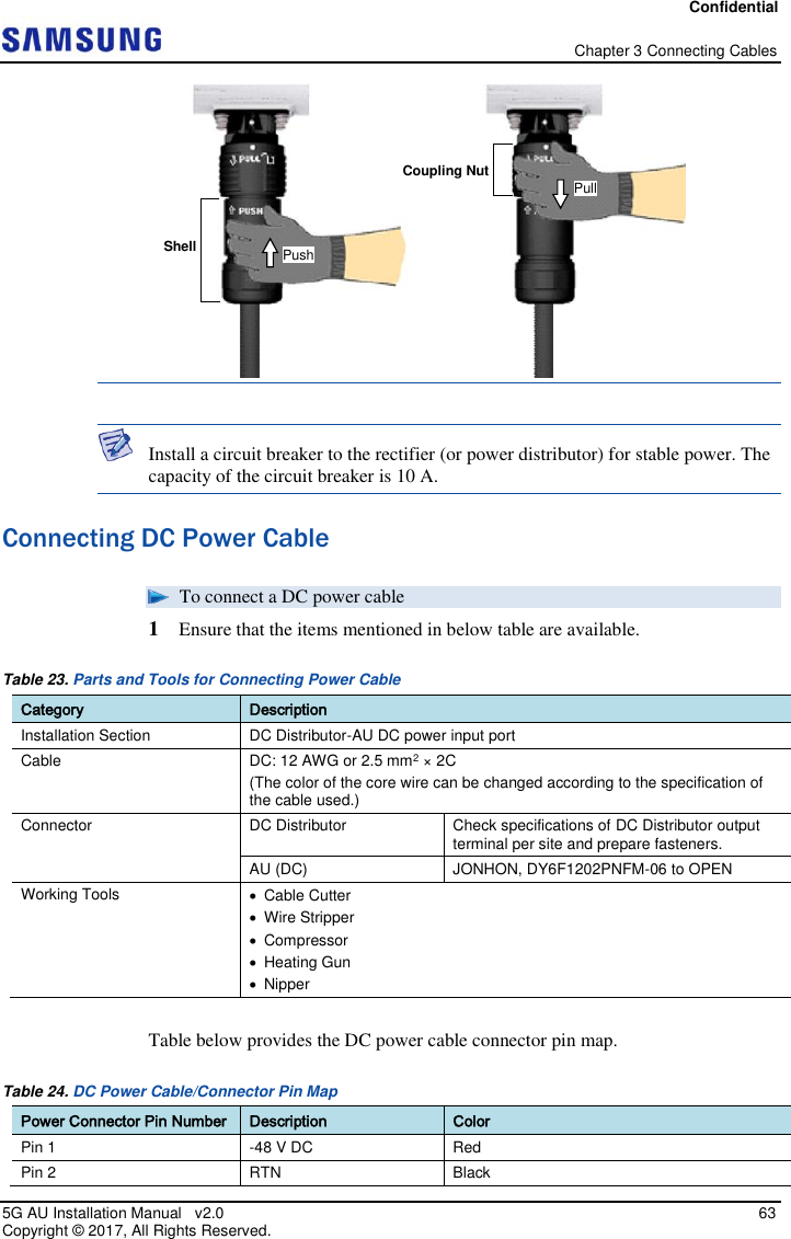
![Confidential Chapter 3 Connecting Cables 5G AU Installation Manual v2.0 62 Copyright © 2017, All Rights Reserved. Figure 47. Connecting AC Power Cable (3) When the connector is fastened tight, the white line on the system side connector becomes invisible (or hidden). The method for connecting or disconnecting the power connector is as follows: - For connecting the connector, push the shell to upper side. - For disconnecting the connector, pull the coupling nut to lower side. This is depicted in figure below. System side connector’s white dot Cable side connector’s white dot Shell Push White Line [White Line is invisible] [White Line is visible]](https://usermanual.wiki/Samsung-Electronics-Co/SFG-AA100DC/User-Guide-3754736-Page-76.png)
![Confidential Chapter 3 Connecting Cables 5G AU Installation Manual v2.0 64 Copyright © 2017, All Rights Reserved. Power Connector Pin Number Description Color 2 Install the DC power cable from the DC Distributor to the AU, as shown in figure below. Figure 48. Connecting DC Power Cable (1) 3 Separate the cap from the cable side connector, as shown in figure below. Figure 49. Connecting DC Power Cable (2) 4 Insert the connector aligning white dot of the cable side connector and white dot of the system side connector. When inserting the connector, push the shell [Cable side Connector] [System side Connector] 1 2 1 2 [Bottom View] DC Distributor DC Power Cable Cap Cap](https://usermanual.wiki/Samsung-Electronics-Co/SFG-AA100DC/User-Guide-3754736-Page-78.png)
![Confidential Chapter 3 Connecting Cables 5G AU Installation Manual v2.0 65 Copyright © 2017, All Rights Reserved. to upper side, as shown in figure below. Figure 50. Connecting DC Power Cable (3) When the connector is fastened tight, the white line on the system side connector becomes invisible (or hidden). The method for connecting or disconnecting the power connector is as follows: - For connecting the connector, push the shell to upper side. - For disconnecting the connector, pull the coupling nut to lower side. This is depicted in figure below. System side connector’s white dot Cable side connector’s white dot Shell Push White Line [White Line is invisible] [White Line is visible]](https://usermanual.wiki/Samsung-Electronics-Co/SFG-AA100DC/User-Guide-3754736-Page-79.png)
![Confidential Chapter 3 Connecting Cables 5G AU Installation Manual v2.0 67 Copyright © 2017, All Rights Reserved. Interface Cable Connection This section describes the procedures to connect interface cables. Remove/Insert Optical Module This section describes the process to follow if an optical module needs to be removed or inserted before connecting the cable. Each step is followed by its corresponding figure showing the location of the parts and direction of movement. To remove the optical module 1 Hang the hook of Optical Transceiver Removal Tool (OTRT) on the bail of the optical module within the system. Figure 51. Optical Module Removal (1) 2 Completely remove the optical module from the transceiver by pulling the OTRT. Figure 52. Optical Module Removal (2) 3 Remove the optical module and the jig by pressing the hook grip of the OTRT. Figure 53. Optical Module Removal (3) Optical Connector Optical Module [System Inside] Optical Transceiver Removal Tool’s Hook Bail [Front View] Location to hang the Optical Transceiver Removal Tool Optical Transceiver Removal Tool Optical Module Transceiver](https://usermanual.wiki/Samsung-Electronics-Co/SFG-AA100DC/User-Guide-3754736-Page-81.png)
![Confidential Chapter 3 Connecting Cables 5G AU Installation Manual v2.0 68 Copyright © 2017, All Rights Reserved. To insert the optical module Push the optical module into the transceiver within the connector. Figure 54. Optical Module Inset Insert the optical module bail, facing the front of the system, to the port. Do not insert when the optic module bail is unlocked. Connecting UDA Cable To connect a UDA cable 1 Ensure that the items mentioned in below table are available. Table 25. Parts and Tools for Connecting UDA Cable Category Description Installation Section AU UDA Port~External alarm device Cable UDA Cable Assembly (24 AWG, 5C) Connector External alarm device Check specifications of external device output terminal per site and prepare fasteners. AU JONHON, Push Pull Type, RJ45MF-CT-07 [System Inside] Transceiver Optical Module Optical Connector Optical Module Bail Optical Module Bail [Raised: Lock] [Lowered: Unlock]](https://usermanual.wiki/Samsung-Electronics-Co/SFG-AA100DC/User-Guide-3754736-Page-82.png)
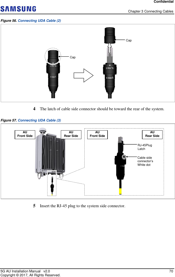
![Confidential Chapter 3 Connecting Cables 5G AU Installation Manual v2.0 69 Copyright © 2017, All Rights Reserved. Category Description Working Tools Cable Cutter Wire Stripper Nipper LAN Tool Table below provides the UDA cable pin map. Table 26. UDA Cable Pin Map System Side Color Map Description 1 White/Blue UDA Common RTN 2 Blue UDA3 3 Orange UDA2 4 Green UDA1 5 Brown UDA0 6 N.C N.C 7 N.C N.C 8 N.C N.C Shell - - 2 Install the UDA cable from the external alarm device to the AU. Figure 55. Connecting UDA Cable (1) 3 Separate the cap from the cable side connector. [Bottom View] External Alarm Device UDA Cable](https://usermanual.wiki/Samsung-Electronics-Co/SFG-AA100DC/User-Guide-3754736-Page-83.png)
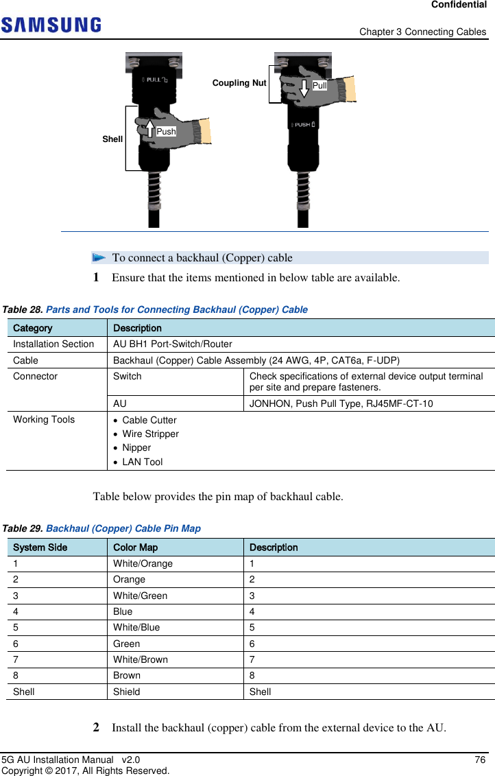
![Confidential Chapter 3 Connecting Cables 5G AU Installation Manual v2.0 72 Copyright © 2017, All Rights Reserved. The method for connecting or disconnecting the backhaul (RJ45) connector is as follows: - For connecting the connector, push the shell to upper side. - For disconnecting the connector, pull the coupling nut to lower side. Connecting Backhaul Cable To connect a backhaul (optical) cable 1 Ensure that the items mentioned in below table are available. Table 27. Parts and Tools for Connecting Backhaul (Optical) Cable Category Description Installation Section AU BH0 Port-Switch/Router Cable Backhaul (Optical) Cable (Optical, Single Mode, for Outdoor Type) Connector AU JONHON, Push Pull Type, PDLC03T03 (DLC/UPC) Working Tools Optical Connector Cleaner The laser beam light runs through the optical cable in the system. The laser beam can cause serious injury to worker's eyes. Therefore, avoid direct exposure to the laser source. White Line [White Line is invisible] [White Line is visible] Shell Coupling Nut Push Pull](https://usermanual.wiki/Samsung-Electronics-Co/SFG-AA100DC/User-Guide-3754736-Page-86.png)
![Confidential Chapter 3 Connecting Cables 5G AU Installation Manual v2.0 73 Copyright © 2017, All Rights Reserved. Remove the cap of the optical connector before connecting. - Before connecting the optical cable, check if the ferrule of the connector is soiled. Be careful to keep the cutting section away from dust or foreign material. If the cable is soiled with foreign material, do not blow to remove them. - Ensure to clean the connector in accordance with the cleaning directions described in Appendix B. - Do not touch the ferrule at the end of optical cable because it is easy to be damaged. 2 Install the backhaul (optical) cable from the AU (BH0 port) to the switch/router. Figure 60. Connecting Backhaul (Optical) Cable (1) 3 Separate the cap from the cable side connector. Figure 61. Connecting Backhaul (Optical) Cable (2) [Before Removing Cap] [After Removing Cap] Cap Ferrule [Bottom View] Switch/Router Backhaul (Optical) Cable Cap Cap Cap Cap DLC Plug](https://usermanual.wiki/Samsung-Electronics-Co/SFG-AA100DC/User-Guide-3754736-Page-87.png)
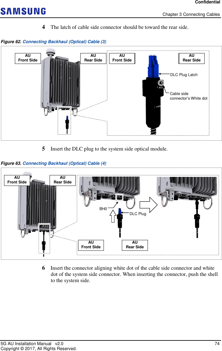
![Confidential Chapter 3 Connecting Cables 5G AU Installation Manual v2.0 75 Copyright © 2017, All Rights Reserved. Figure 64. Connecting Backhaul (Optical) Cable (5) When the connector is fastened tight, the white line on the system side connector becomes invisible (or hidden). The method for connecting or disconnecting the backhaul (optical) connector is as follows: - For connecting the connector, push the shell to upper side. - For disconnecting the connector, pull the coupling nut to lower side. AU Front Side AU Rear Side AU Front Side AU Rear Side White dot White Line [White Line is invisible] [White Line is visible]](https://usermanual.wiki/Samsung-Electronics-Co/SFG-AA100DC/User-Guide-3754736-Page-89.png)
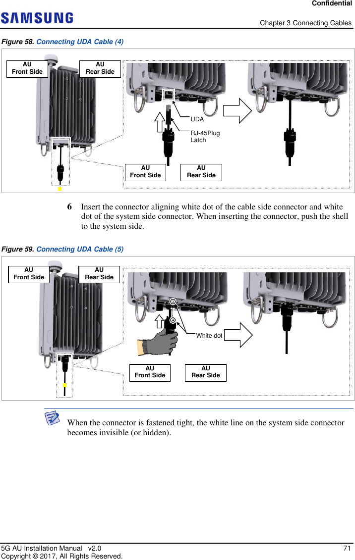
![Confidential Chapter 3 Connecting Cables 5G AU Installation Manual v2.0 77 Copyright © 2017, All Rights Reserved. Figure 65. Connecting Backhaul (Copper) Cable (1) 3 Separate the cap from the cable side connector. Figure 66. Connecting Backhaul (Copper) Cable (2) 4 The latch of cable side connector should be toward the rear of the system. Figure 67. Connecting Backhaul (Copper) Cable (3) [Bottom View] Switch/Router Backhaul (Copper) Cable Cap Cap AU Front Side AU Rear Side AU Rear Side AU Front Side RJ-45Plug Latch Cable side connector’s White dot](https://usermanual.wiki/Samsung-Electronics-Co/SFG-AA100DC/User-Guide-3754736-Page-91.png)
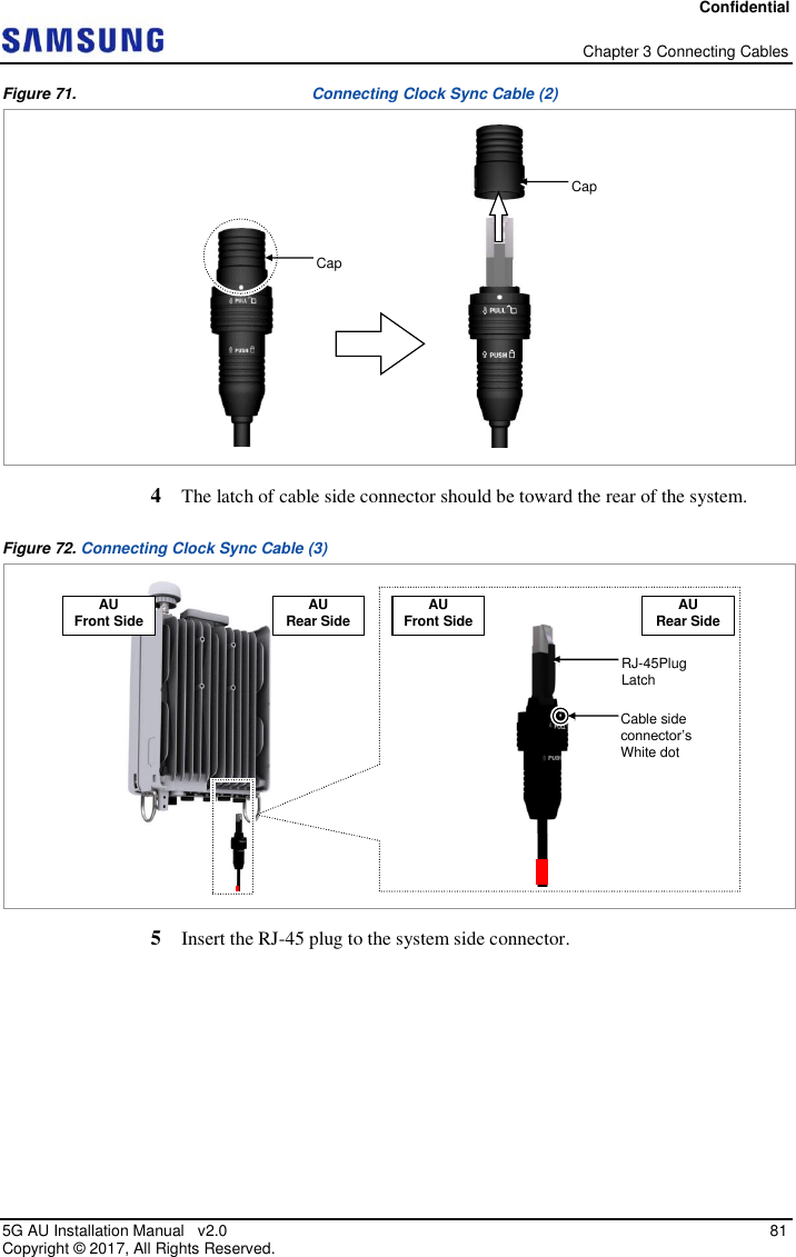
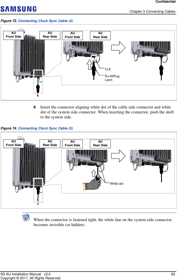
![Confidential Chapter 3 Connecting Cables 5G AU Installation Manual v2.0 79 Copyright © 2017, All Rights Reserved. The method for connecting or disconnecting the backhaul (RJ45) connector is as follows: - For connecting the connector, push the shell to upper side. - For disconnecting the connector, pull the coupling nut to lower side. Connecting Clock Sync Cable To connect a clock sync cable The clock sync cable is only used for 2 sector cascade installation. 1 Ensure that the items mentioned in below table are available. Table 30. Parts and Tools for Connecting Clock Sync Cable Category Description Installation Section #0 AU CLK Port-#1 AU CLK Port Cable Clock sync Cable Assembly (24 AWG, 4P, CAT5e, S-FTP) Connector #0 AU JONHON, Push Pull Type, RJ45MF-CT-07 #1 AU JONHON, Push Pull Type, RJ45MF-CT-07 Working Tools Cable Cutter Wire Stripper Nipper White Line [White Line is invisible] [White Line is visible] Shell Coupling Nut Push Pull](https://usermanual.wiki/Samsung-Electronics-Co/SFG-AA100DC/User-Guide-3754736-Page-93.png)
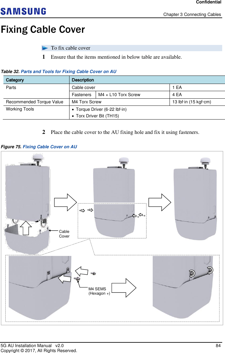
![Confidential Chapter 3 Connecting Cables 5G AU Installation Manual v2.0 80 Copyright © 2017, All Rights Reserved. Category Description LAN Tool Table below provides the clock sync cable pin map. Table 31. Clock Sync Cable Pin Map AU #0 Side Color Map AU #1 Side 1 White/Orange 5 2 Orange 6 3 White/Green 4 4 Green 3 5 White/Blue 1 6 Blue 2 7 Cut 7 8 Cut 8 Shell - Shell 2 Install the clock sync cable from the external alarm device to the AU. Figure 70. Connecting Clock Sync Cable (1) 3 Separate the cap from the cable side connector. [Bottom View] CLK Cable [Bottom View]](https://usermanual.wiki/Samsung-Electronics-Co/SFG-AA100DC/User-Guide-3754736-Page-94.png)
![Confidential Chapter 3 Connecting Cables 5G AU Installation Manual v2.0 83 Copyright © 2017, All Rights Reserved. The method for connecting or disconnecting the backhaul (RJ45) connector is as follows: - For connecting the connector, push the shell to upper side. - For disconnecting the connector, pull the coupling nut to lower side. White Line [White Line is invisible] [White Line is visible] Shell Coupling Nut Push Pull](https://usermanual.wiki/Samsung-Electronics-Co/SFG-AA100DC/User-Guide-3754736-Page-97.png)

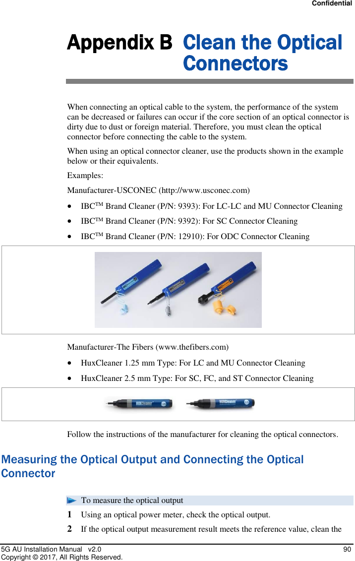
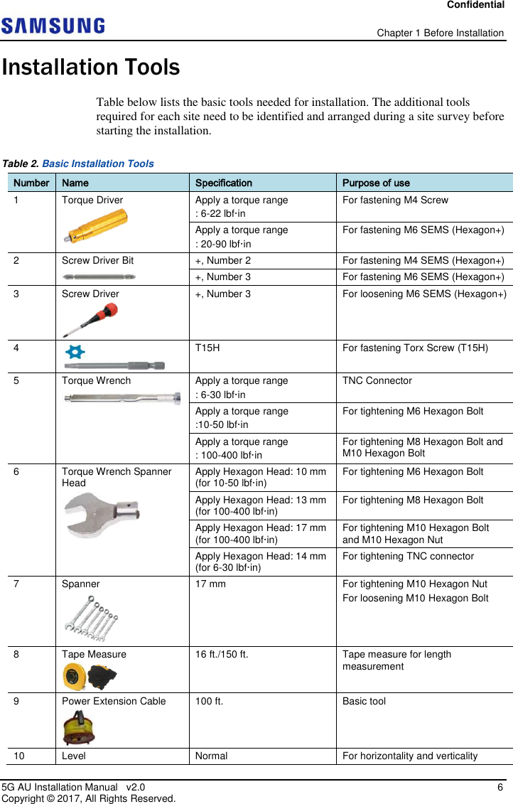
![Confidential Appendix B Clean the Optical Connectors 5G AU Installation Manual v2.0 91 Copyright © 2017, All Rights Reserved. connector again and connect it. 3 If the measurement result does not meet the reference value, discard the cable and replace it with a new cable. Clean the new cable and connect it to the system. [Optical Power meter] [LC/PC Plug]](https://usermanual.wiki/Samsung-Electronics-Co/SFG-AA100DC/User-Guide-3754736-Page-105.png)