Samsung Electronics Co SIP005AFS30 ARTIK-0530 User Manual ARTIK 5 Datasheet
Samsung Electronics Co Ltd ARTIK-0530 ARTIK 5 Datasheet
Contents
- 1. User Manual_20160929_v1 - 06_ARTIK530DevBoardUserGuide_Draft_0928
- 2. User Manual_20161006_v2 - 06_SIP007AFS00_manual_final
- 3. User Manual addendum for Full Modular Approval
User Manual_20160929_v1 - 06_ARTIK530DevBoardUserGuide_Draft_0928

SAMSUNG ELECTRONICS RESERVES THE RIGHT TO CHANGE PRODUCTS, INFORMATION AND SPECIFICATIONS WITHOUT NOTICE.
Products and specifications discussed herein are for reference purposes only. All information discussed herein is provided on an "AS IS" b asis, without warranties
of any kind. This document and all information discussed herein remain the sole and exclusive property of Samsung Electronics. No license of any patent,
copyright, mask work, trademark or any other intellectual property right is granted by one party to the other party under this document, by implication, estoppel
or other-wise. Samsung products are not intended for use in life support, critical care, medical, safety equipment, or similar applications where product failure
could result in loss of life or personal or physical harm, or any military or defense application, or any governmental procurement to which special terms or
provisions may apply. For updates or additional information about Samsung products, contact your nearest Samsung office. All brand names, trademarks and
registered trademarks belong to their respective owners.

Samsung Semiconductor, Inc. ARTIK 530 Development Board User Guide
Samsung Confidential
Specifications in this document are tentative and subject to
change.
2
TABLE OF CONTENTS
Table of Contents ................................................................................................................................................................... 2
List of Figures .......................................................................................................................................................................... 3
List of Tables ........................................................................................................................................................................... 3
Version History ...................................................................................................................................................................................... 4
Handling Guide ....................................................................................................................................................................... 5
ARTIK 530 Development Board Overview ........................................................................................................................... 6
features .................................................................................................................................................................................................. 6
Block diagram ....................................................................................................................................................................................... 7
Mechanical Drawings ........................................................................................................................................................................... 7
ARTIK 530 Module ................................................................................................................................................................ 10
ARTIK 530 Module Specification ........................................................................................................................................................ 10
ARTIK 530 Development Board Interposer Board ........................................................................................................... 11
Interposer Board Boot mode Configuration .................................................................................................................................... 12
USB OTG ............................................................................................................................................................................................... 13
HDMI 1.4a ............................................................................................................................................................................................ 13
LVDS ..................................................................................................................................................................................................... 14
Ethernet................................................................................................................................................................................................ 14
Antenna ................................................................................................................................................................................................ 15
ARTIK 530 Development Board Platform Board .............................................................................................................. 16
Configuration of External Power Source .......................................................................................................................................... 17
SD-Card Interface................................................................................................................................................................................ 17
EarJack Interface ................................................................................................................................................................................. 18
MIPI DSI/CSI Interface ......................................................................................................................................................................... 18
USB Host 2.0 Interface ....................................................................................................................................................................... 19
Connector to IF Board Interface ........................................................................................................................................................ 20
ARTIK 530 Development Board IF Board .......................................................................................................................... 21
Preview on the ARTIK IF board .......................................................................................................................................................... 21
Configuration of external Power Source .......................................................................................................................................... 22
ARTIK 530 Development Board Booting ........................................................................................................................... 23
Serial Port Connection ....................................................................................................................................................................... 23
Terminal Emulator Installation ......................................................................................................................................................... 24
Power on the ARTIK 530 Development Board.................................................................................................................................. 25
Network Settings ................................................................................................................
오류! 책갈피가 정의되어 있지 않습니다.
How to use sftp ..................................................................................................................
오류! 책갈피가 정의되어 있지 않습니다.
How to use ssh ...................................................................................................................
오류! 책갈피가 정의되어 있지 않습니다.
Package installation ..........................................................................................................
오류! 책갈피가 정의되어 있지 않습니다.
Legal Information ................................................................................................................................................................. 27

Samsung Semiconductor, Inc. ARTIK 530 Development Board User Guide
Samsung Confidential
Specifications in this document are tentative and subject to
change.
3
LIST OF FIGURES
Figure 1. Preview of the ARTIK 530 Board ............................................................................................................................ 6
Figure 2. ARTIK 530 Development Board .............................................................................................................................. 7
Figure 3. Mechanical Drawing ARTIK 530 Development Board Interposer Board all dimensions are in [mm] .......... 8
Figure 4. Mechanical Drawing ARTIK 530 Development Board Platform Board all dimensions are in [mm] ............. 9
Figure 5. ARTIK 530 Development Board Interposer Board Left Top Side, Right Bottom Side .................................. 11
Figure 6. ARTIK 530 Development Board Booting Switch Location ................................................................................ 12
Figure 7. USB OTG Interface location on the Interposer Board ...................................................................................... 13
Figure 8. HDMI 1.4a Interface location on the Interposer Board ................................................................................... 13
Figure 9. LVDS Interface location on the Interposer Board ............................................................................................. 14
Figure 10. Ethernet Interface location on the Interposer Board .................................................................................... 14
Figure 11. Antenna location on the Interposer Board ..................................................................................................... 15
Figure 12. ARTIK 530 Development Board Platform Board Left Bottom Side, Right Top Side ................................... 16
Figure 13. Jumper Interface locations JP1-JP4 on the Platform Board ........................................................................... 17
Figure 14. SD-Card Interface location on the Platform Board ........................................................................................ 17
Figure 15. Ear Jack Interface location on the Platform Board ......................................................................................... 18
Figure 16. MIPI DSI Interface location on the Platform Board ........................................................................................ 18
Figure 17. MIPI CSI Interface Location on the Platform Board ....................................................................................... 19
Figure 18 USB2.0 Interface location on the Platform Board ........................................................................................... 19
Figure 19. Expansion Connector Interface location on the Platform Board ................................................................. 20
Figure 20. ARTIK 530 Development Board IF Board ......................................................................................................... 21
Figure 21. Jumper Interface locations J20, J21 on the IF Board ....................................................................................... 22
Figure 22. Typical Linux Serial Console .............................................................................................................................. 23
Figure 23. USB Serial Cable hooked up to the Platform Board ....................................................................................... 24
Figure 24 Connection Power adaptor with development Board .................................................................................... 25
Figure 25. Power switch location on the development Board ........................................................................................ 25
Figure 26. Power button location on the development Board ....................................................................................... 26
LIST OF TABLES
Table 1. Main Features of the ARTIK 530 Module ............................................................................................................. 10
Table 2. Boot option that can be set on the Interposer Board ....................................................................................... 12
Table 3 Antenna spec ........................................................................................................................................................... 15
Table 4. Connector J2 ............................................................................................................................................................ 21
Table 5. Connector J3 ............................................................................................................................................................ 22
Samsung Semiconductor, Inc. ARTIK 530 Development Board User Guide
Samsung Confidential
Specifications in this document are tentative and subject to
change.
4
VERSION HISTORY
Revision
Date
Description
Maturity

Samsung Semiconductor, Inc. ARTIK 530 Development Board User Guide
Samsung Confidential
Specifications in this document are tentative and subject to
change.
5
HANDLING GUIDE
Precaution against Electrostatic Discharge
When using the ARTIK 530 Board, ensure that the environment is protected against static electricity:
Contamination
Do not use the ARTIK 530 Board in an environment exposed to dust or dirt adhesion.
Temperature/Humidity
The ARTIK 530 Board is sensitive to:
1. Environment
2. Temperature
3. Humidity
High temperature or humidity deteriorates the characteristics of ARTIK 530 Board, therefore, do not store or use the ARTIK
530 Board under such conditions.
Mechanical Shock
Do not to apply excessive mechanical shock or force on the ARTIK 530 Board.
Chemical
Do not expose the ARTIK 530 Board to chemicals. Exposure to chemicals leads to reactions that deteriorate the
characteristics of the ARTIK 530 Board.
EMS (Electro Magnetic Susceptibility)
Strong electromagnetic waves or magnetic fields may affect the characteristics of the ARTIK 530 Board during the operation
under insufficient PCB circuit design for Electro Magnetic Susceptibility (EMS).
Samsung Semiconductor, Inc. ARTIK 530 Development Board User Guide
Samsung Confidential
Specifications in this document are tentative and subject to
change.
6
ARTIK 530 DEVELOPMENT BOARD OVERVIEW
FEATURES
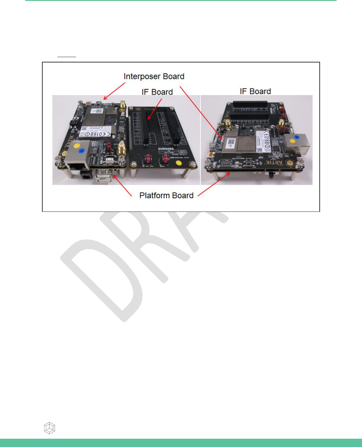
The ARTIK 530 Development Board consists of 1x Interposer Board , 1x Platform Board, and 1x IF Board. The Interposer
Board does include the ARTIK 530 Module. The ARTIK 530 Development Board is an affordable approach for developing an
IoT solution. Figure 1 show the locations of the various boards that make up the ARTIK 530 Development Board.
Figure 1. Preview of the ARTIK 530 Board
Samsung Semiconductor, Inc. ARTIK 530 Development Board User Guide
Samsung Confidential
Specifications in this document are tentative and subject to
change.
7
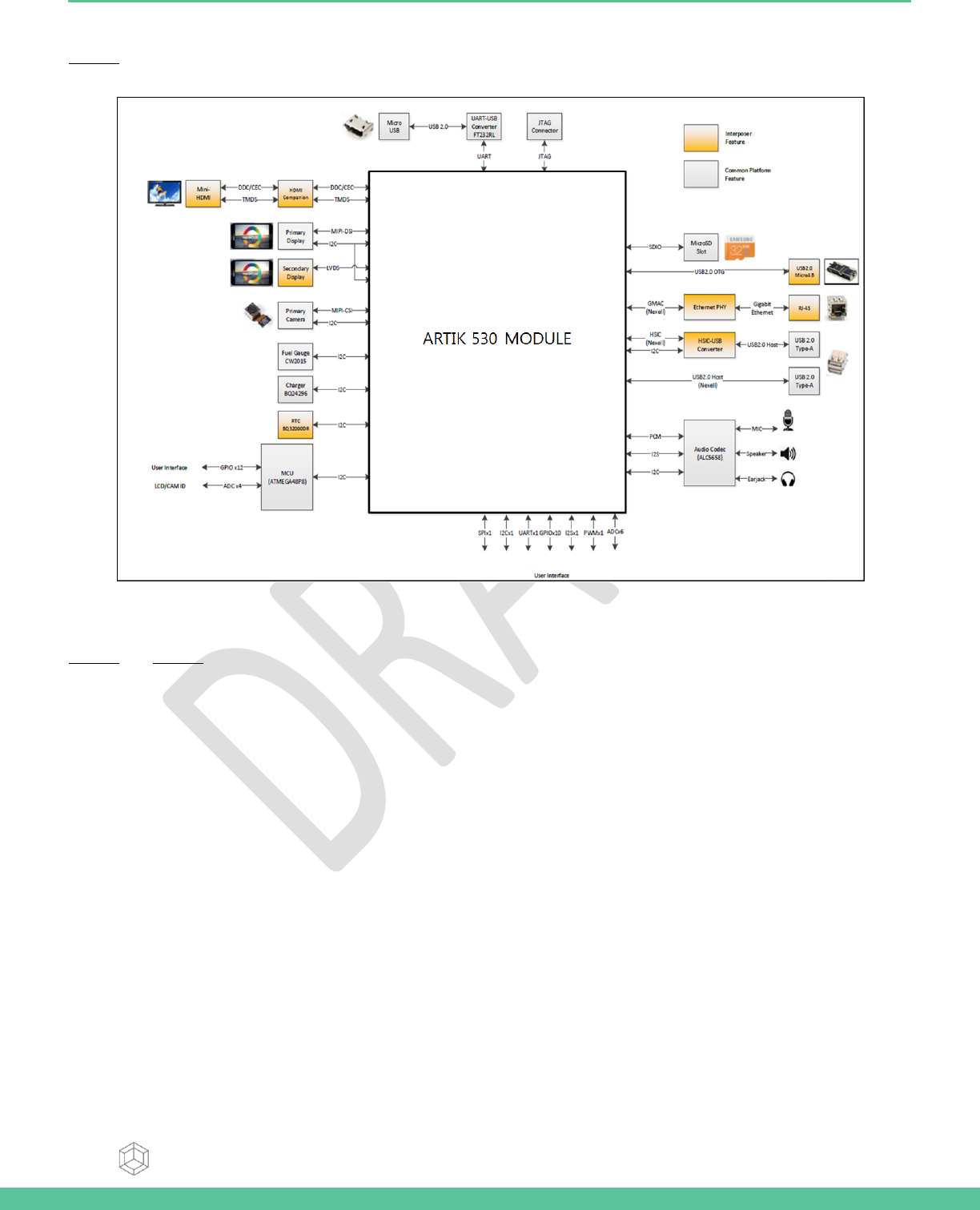
BLOCK DIAGRAM
Figure 2 shows the block diagram of the ARTIK 530 Development Board, if you want more information on the ARTIK 530
Module please consult the ARTIK 530 Module Datasheet.
Figure 2. ARTIK 530 Development Board
MECHANICAL DRAWINGS
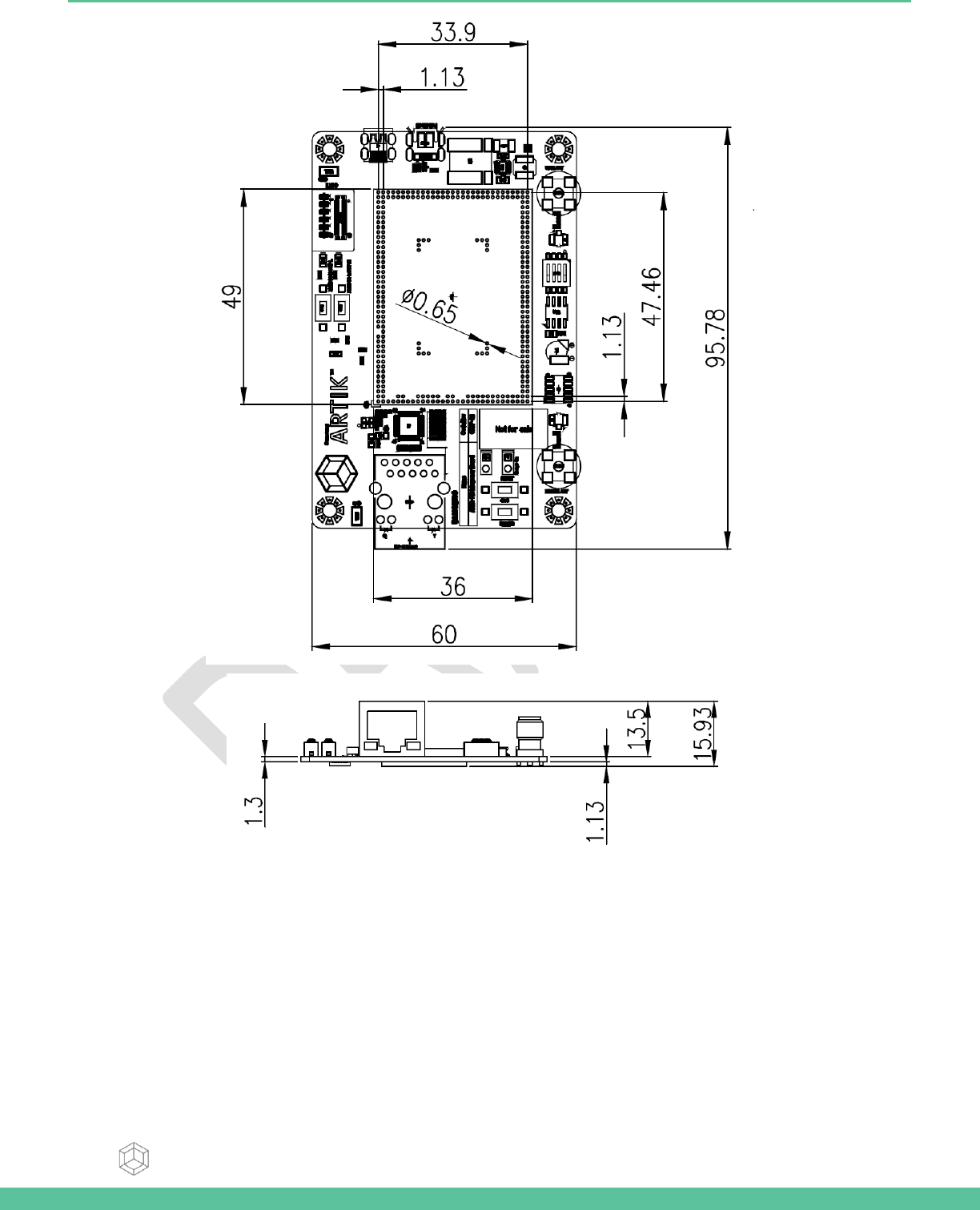
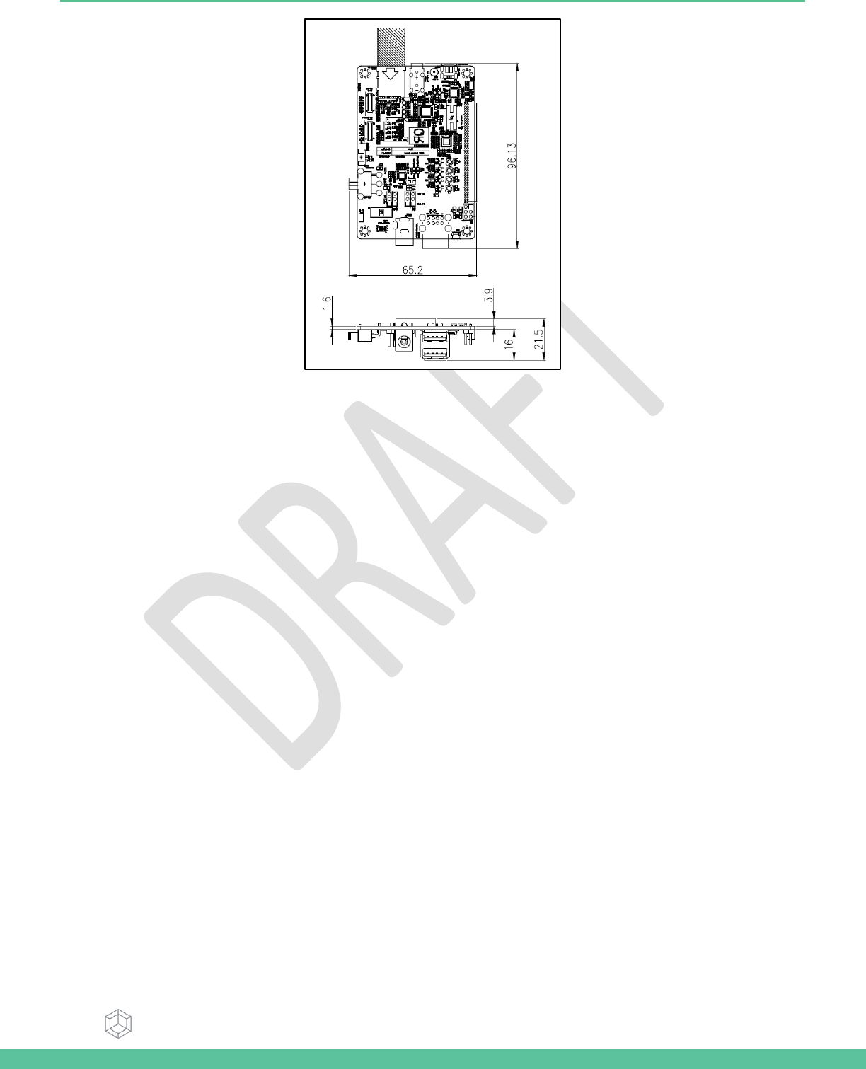
Figure 3 and Figure 4 show the ARTIK 530 Development Board Interposer Board and the Platform Board respectively.
Samsung Semiconductor, Inc. ARTIK 530 Development Board User Guide
Samsung Confidential
Specifications in this document are tentative and subject to
change.
8
Figure 3. Mechanical Drawing ARTIK 530 Development Board Interposer Board all dimensions are in [mm]
Samsung Semiconductor, Inc. ARTIK 530 Development Board User Guide
Samsung Confidential
Specifications in this document are tentative and subject to
change.
9
Figure 4. Mechanical Drawing ARTIK 530 Development Board Platform Board all dimensions are in [mm]
Samsung Semiconductor, Inc. ARTIK 530 Development Board User Guide
Samsung Confidential
Specifications in this document are tentative and subject to
change.
10
ARTIK 530 MODULE
The ARTIK 530 Development Board contains the ARTIK 530 Module. This section will describe some of the main features of
this module. For more information on the ARTIK 530 Module please consult the ARTIK 530 Module datasheet.
ARTIK 530 MODULE SPECIFICATION
The ARTIK 530 Module is designed for IoT devices and it contains a lot of functions based on a Linux system. Not only
multimedia functions but also network functions for example Wi-Fi or ZigBee. In addition the ARTIK 530 Module has mass
storage functionality and its own security solution. Table 1 shows the main features of the ARTIK 530 Module that is part of
the ARTIK 530 Development Board.
Table 1. Main Features of the ARTIK 530 Module
Processor
CPU
4x ARM® Cortex-A9@1.2GHz
GPU
3D graphics accelerator
Media
Camera I/F
4-Lane MIPI CSI
Display
4-Lane MIPI DSI up to FHD@24bpp
Audio
I2S audio interface
Memory
DRAM
512MB DDR3 @ 800MHz
FLASH
4GB eMMC
Security
Secure Element
Secure point to point authentication
and data transfer
Trusted Execution
Environment
Trustware
Radio
WLAN
IEEE 802.11a/b/g/n
Bluetooth
4.2+LE
802.15.4
ZigBee + Thread
Power Management
PMIC
Provides all power of the ARTIK 530
Module using on board bucks and
LDOs
Interfaces
Analog and Digital I/O
GPIO, I2C, SPI, UART, SDIO, USB
2.0, JTAG, Analog Input
Samsung Semiconductor, Inc. ARTIK 530 Development Board User Guide
Samsung Confidential
Specifications in this document are tentative and subject to
change.
11
ARTIK 530 DEVELOPMENT BOARD INTERPOSER BOARD
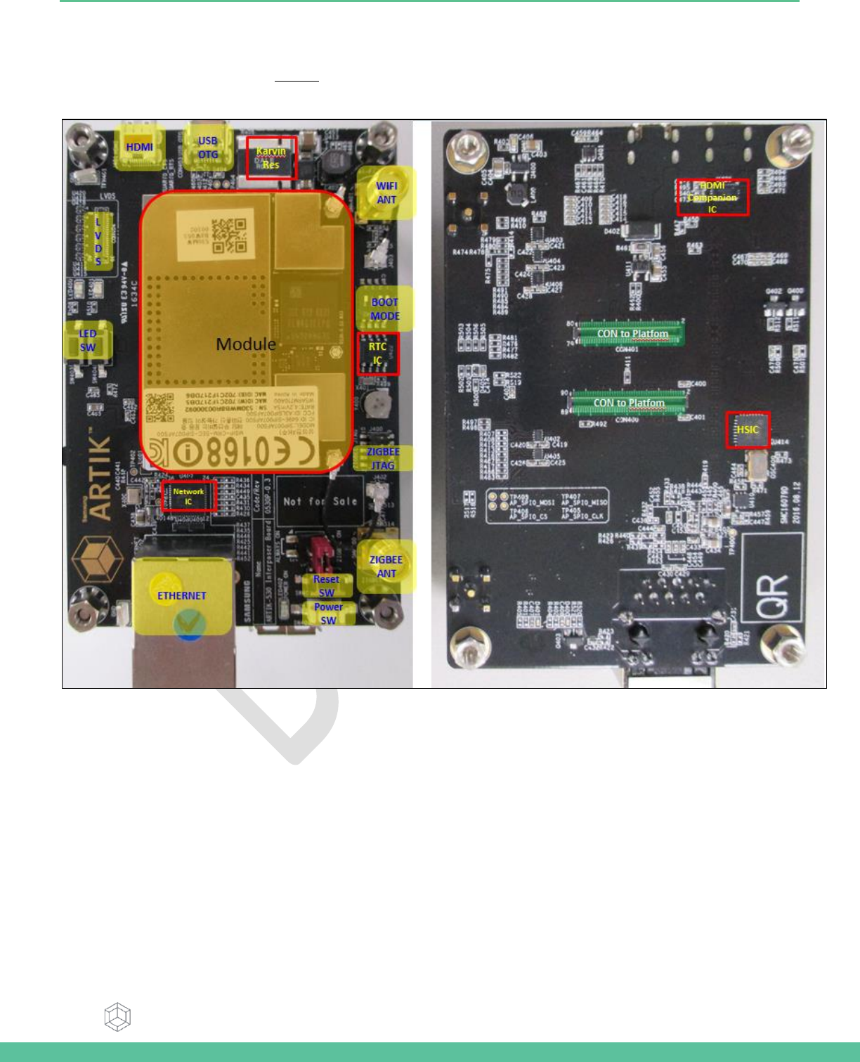
The Interposer Board as depicted in Figure 5 highlights the most important components on the Interposer board.
Figure 5. ARTIK 530 Development Board Interposer Board Left Top Side, Right Bottom Side
Samsung Semiconductor, Inc. ARTIK 530 Development Board User Guide
Samsung Confidential
Specifications in this document are tentative and subject to
change.
12
INTERPOSER BOARD BOOT MODE CONFIGURATION
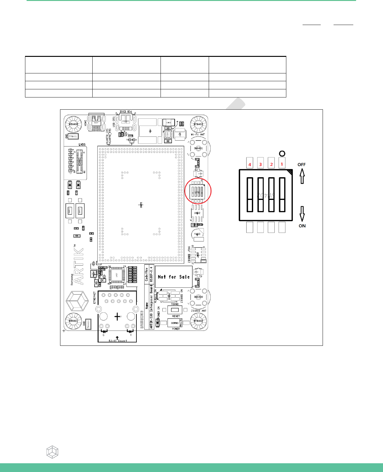
This section describes the various boot modes that are supported on the ARTIK 530 Development Board. Table 2 and Figure 6
show how to manipulate SW4 and where SW4 is located on the Interposer Board to set the various booting options that are
available on the ARTIK 530 Development Board.
Table 2. Boot option that can be set on the Interposer Board
SW4
eMMc
1st Boot
SD Card
1st Boot
USB
1st Boot
AP_GPB13_SD0_BOOT
Off
Off
On
AP_GPB15_SD1_BOOT
Off
Off
On
AP_GPB4_VID1_3_BOOT
Off
On
X
Figure 6. ARTIK 530 Development Board Booting Switch Location
Samsung Semiconductor, Inc. ARTIK 530 Development Board User Guide
Samsung Confidential
Specifications in this document are tentative and subject to
change.
13
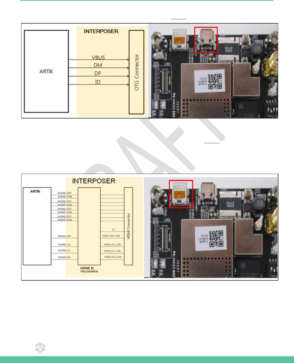
USB OTG
The Interposer board has 1x USB OTG connector located as can be seen in Figure 7.
Figure 7. USB OTG Interface location on the Interposer Board
HDMI 1.4A
The Interposer board has 1x HDMI 1.4a connector (Micro D-Type) located as can be seen in Figure 8. The following video
formats are supported:
1. 480p/480i @59.94Hz/60Hz, 576p/576i@50Hz
2. 720p/720i @50Hz/59.94Hz/60Hz
3. 1080p/1080i @50Hz/59.94Hz/60Hz
Figure 8. HDMI 1.4a Interface location on the Interposer Board
Samsung Semiconductor, Inc. ARTIK 530 Development Board User Guide
Samsung Confidential
Specifications in this document are tentative and subject to
change.
14
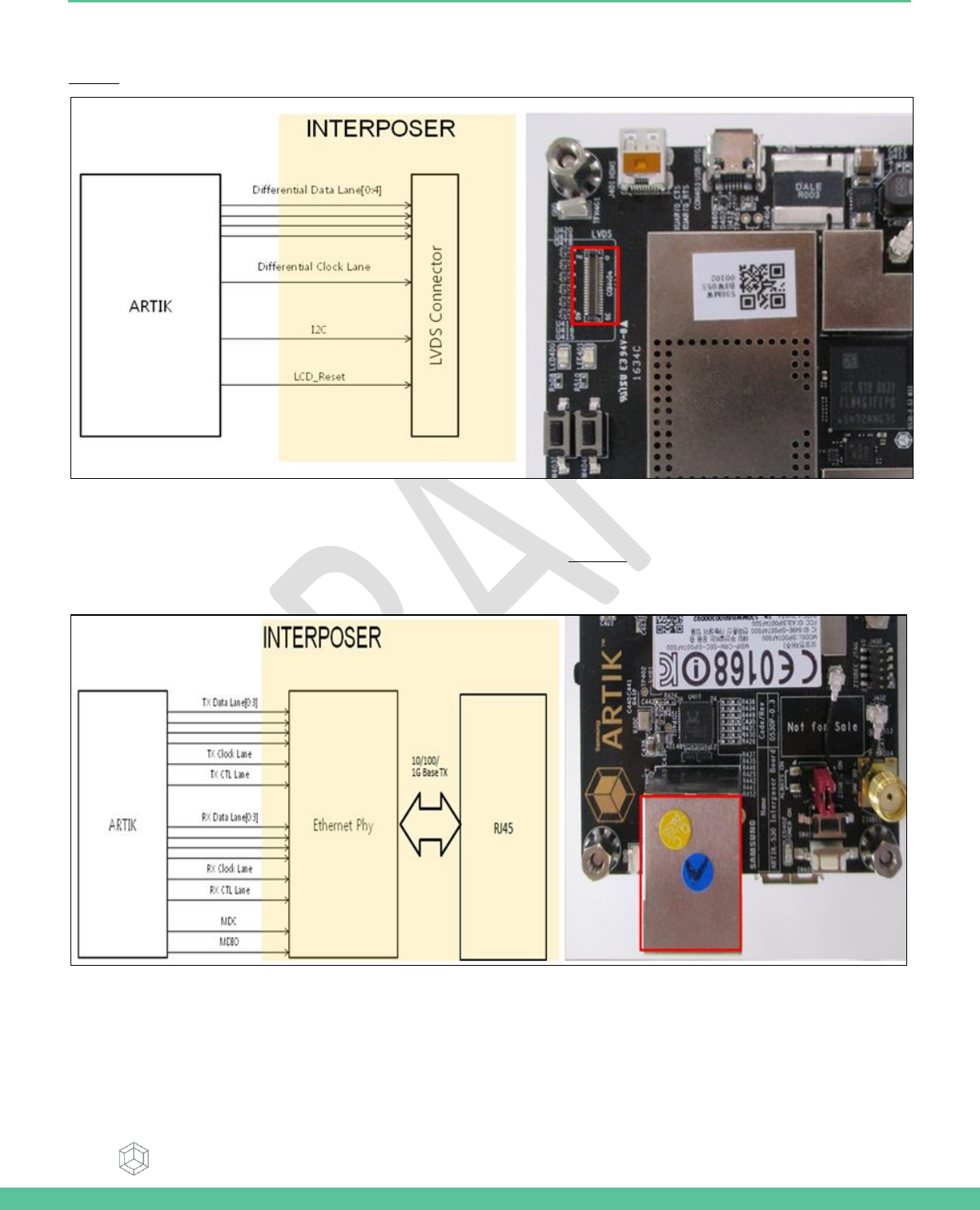
LVDS
The Interposer board has 1x LVDS Interface containing 5x data channels and 1x clock channel, its location can be seen in
Figure 9. The available maximum resolution is 1920x1080@60fps.
Figure 9. LVDS Interface location on the Interposer Board
ETHERNET
The Interposer board has 1x Ethernet Interface, its location can be seen in Figure 10. The Ethernet Interface is based on
802.3az-2010 complying to the Energy Efficient Ethernet (EEE) standard. The maximum theoretical speed of the interface is
1000Mbps.
Figure 10. Ethernet Interface location on the Interposer Board
Samsung Semiconductor, Inc. ARTIK 530 Development Board User Guide
Samsung Confidential
Specifications in this document are tentative and subject to
change.
15
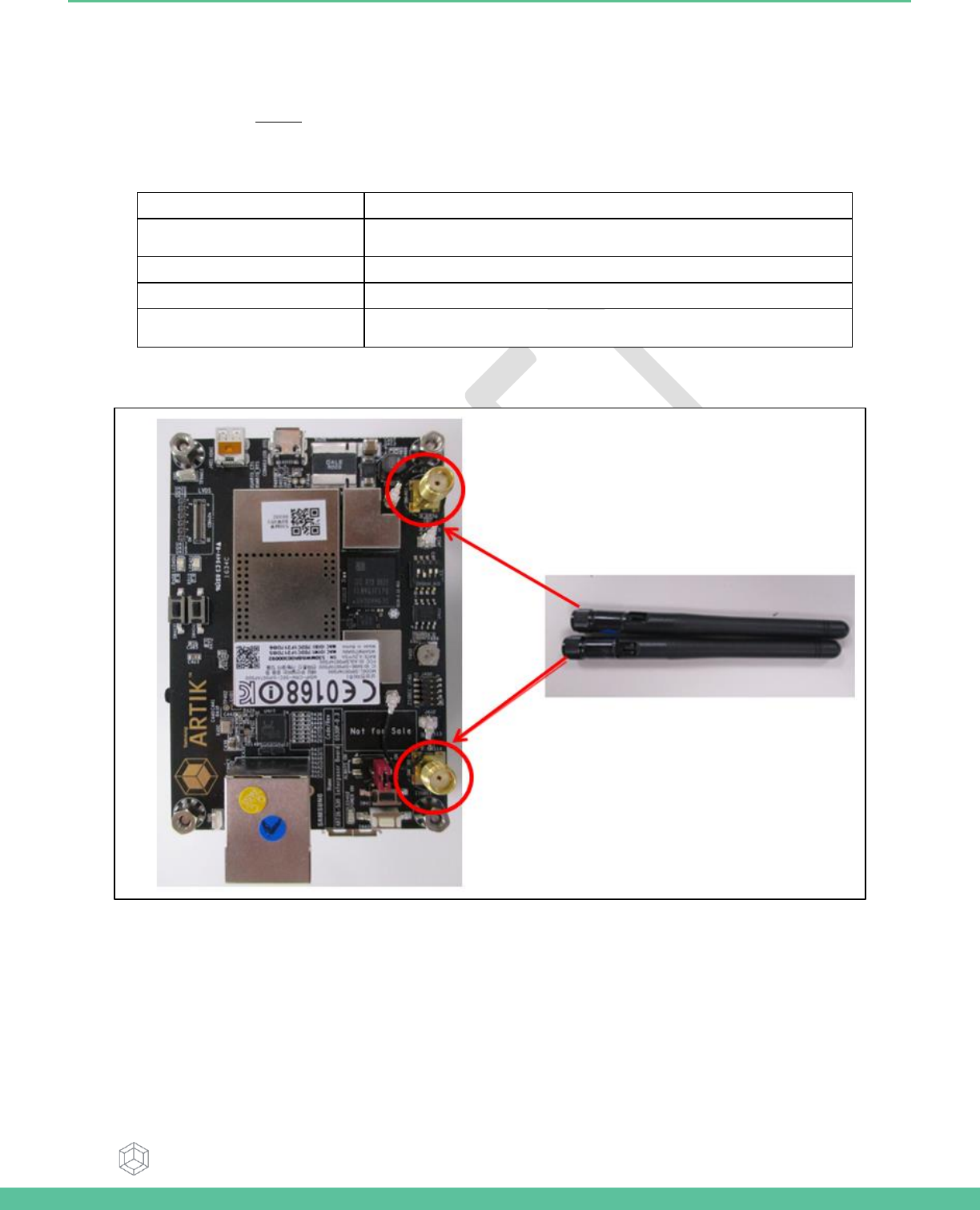
ANTENNA
Antenna which is enclosed in KIT has to be assembled on Interposer board if use Wifi/BT and Zigbee.
Antena spec can be seen in Table 3
Table 3 Antenna spec
Antenna type
Dipole Antenna
Antenna peak gain
+1.43(2.4GHz)/ +0.91(5GHz)
Frequency
2.4GHz, 5GHz (for Wi-Fi, BT, ZigBee)
Connector type
SMA-M
ANT.Size
108.7mm
Figure 11. Antenna location on the Interposer Board
Samsung Semiconductor, Inc. ARTIK 530 Development Board User Guide
Samsung Confidential
Specifications in this document are tentative and subject to
change.
16
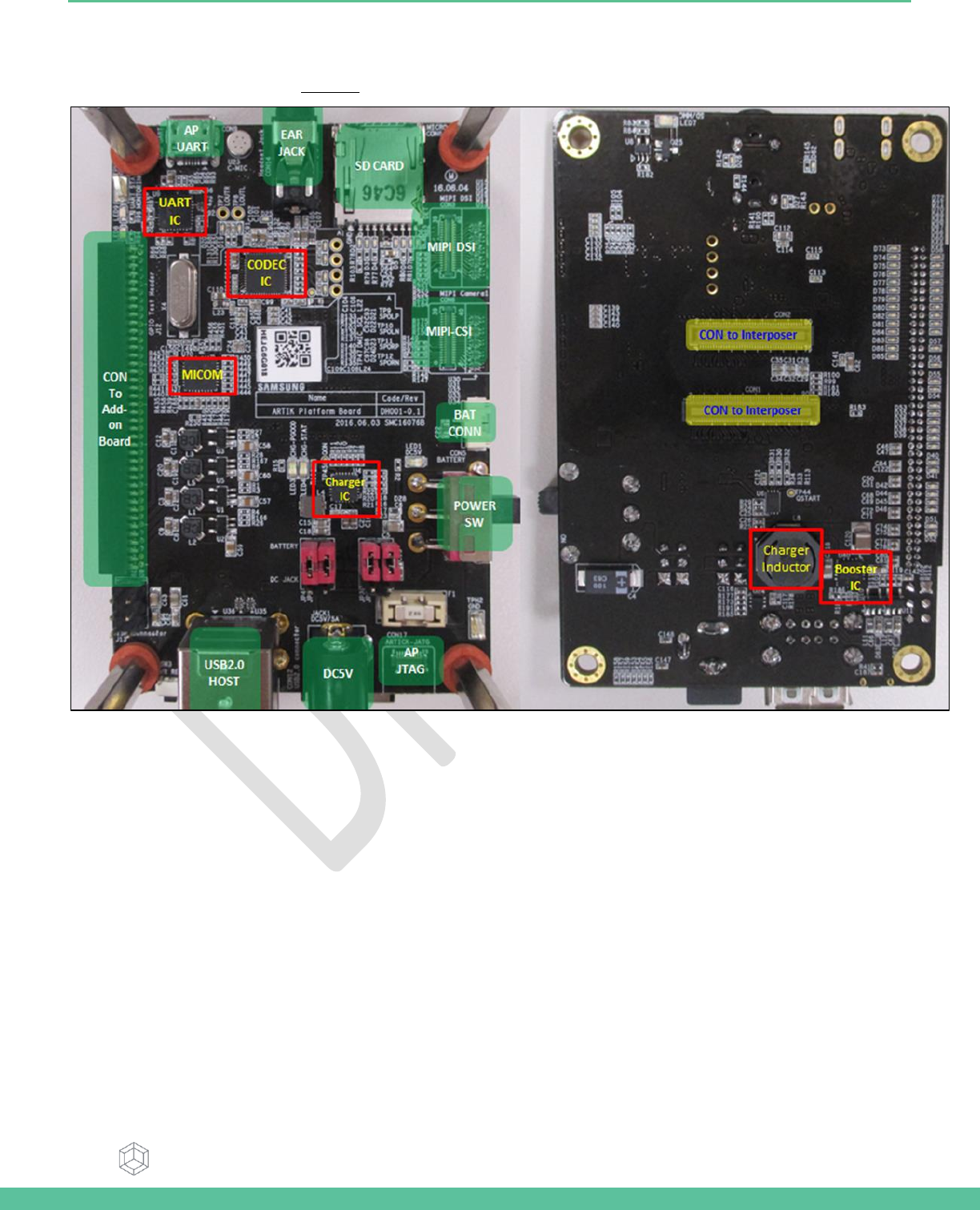
ARTIK 530 DEVELOPMENT BOARD PLATFORM BOARD
The Platform Board as depicted in Figure 12 highlights the most important components on the Interposer board.
Figure 12. ARTIK 530 Development Board Platform Board Left Bottom Side, Right Top Side
Samsung Semiconductor, Inc. ARTIK 530 Development Board User Guide
Samsung Confidential
Specifications in this document are tentative and subject to
change.
17
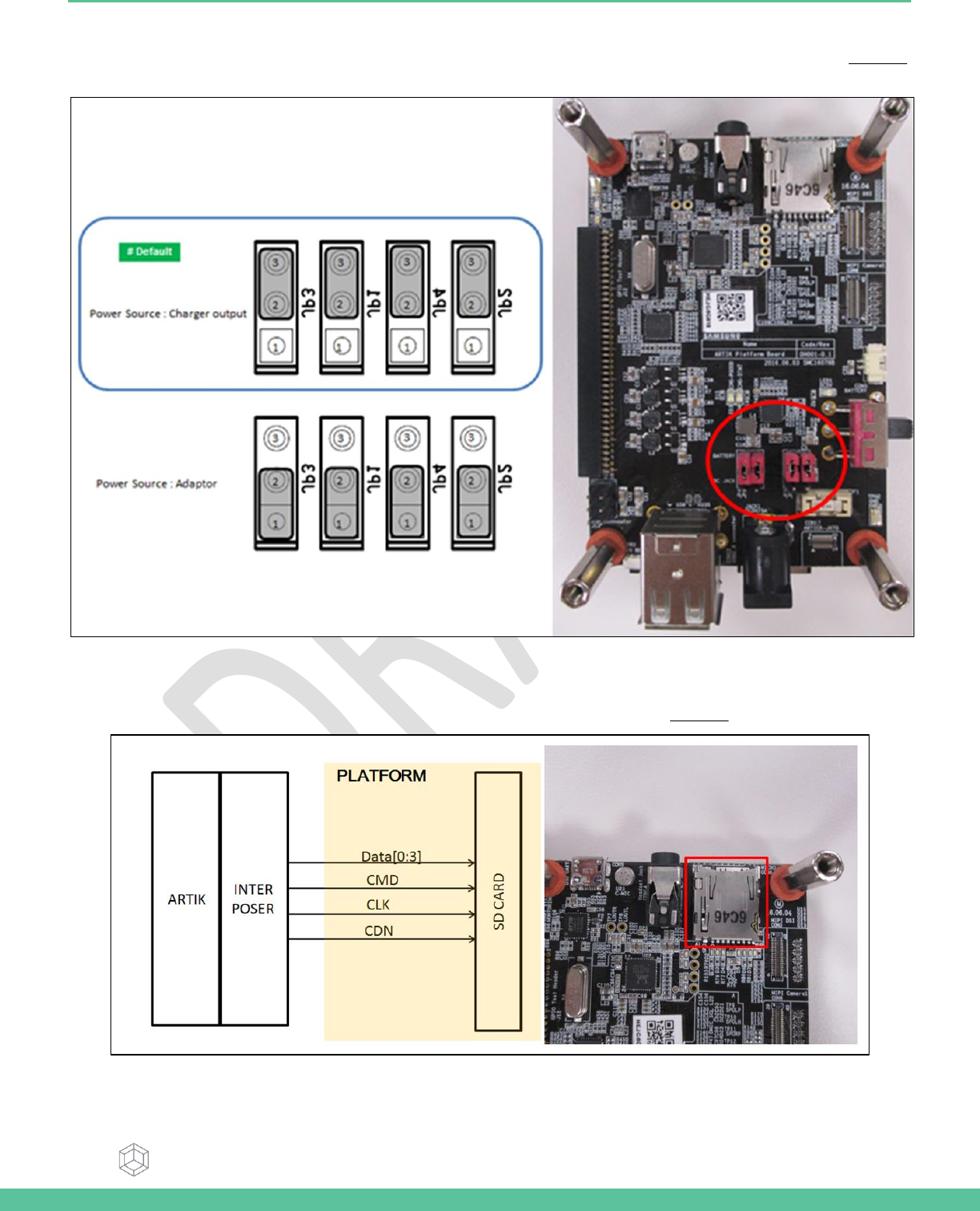
CONFIGURATION OF EXTERNAL POWER SOURCE
Through selection of the Jumpers JP1-JP4 the IO power source can be selected to either DC-5V or to Charger Output. Figure 13
shows how to set the various jumpers to switch between power sources.
Figure 13. Jumper Interface locations JP1-JP4 on the Platform Board
SD-CARD INTERFACE
The Platform board has 1x SD-CARD interface supporting SD3.0 located as can be seen in Figure 14.
Figure 14. SD-Card Interface location on the Platform Board
Samsung Semiconductor, Inc. ARTIK 530 Development Board User Guide
Samsung Confidential
Specifications in this document are tentative and subject to
change.
18
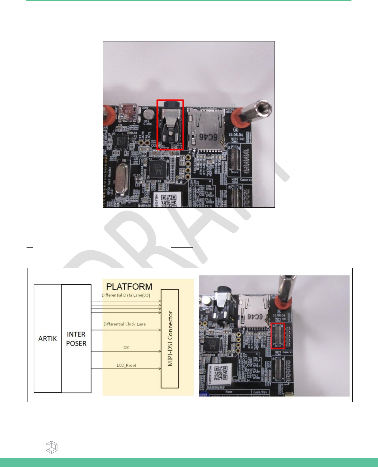
EARJACK INTERFACE
The Platform board has 1x 4 pin ear jack interface supporting stereo audio as can be seen in Figure 15.
Figure 15. Ear Jack Interface location on the Platform Board
MIPI DSI/CSI INTERFACE
The Platform board has 1x MIPI DSI and 1x MIPI CSI interface. The location of the DSI Display interface can be seen in Figure
16. The location of the MIPI CSI interface can be seen in Figure 17.The MIPI DSI interface can operate at a maximum resolution
of WUXGA (1920x1200), whereas the MIPI CSI interface can have a static resolution of 5M pixels or a dynamic resolution for
video capturing of 1080P.
Figure 16. MIPI DSI Interface location on the Platform Board
Samsung Semiconductor, Inc. ARTIK 530 Development Board User Guide
Samsung Confidential
Specifications in this document are tentative and subject to
change.
19
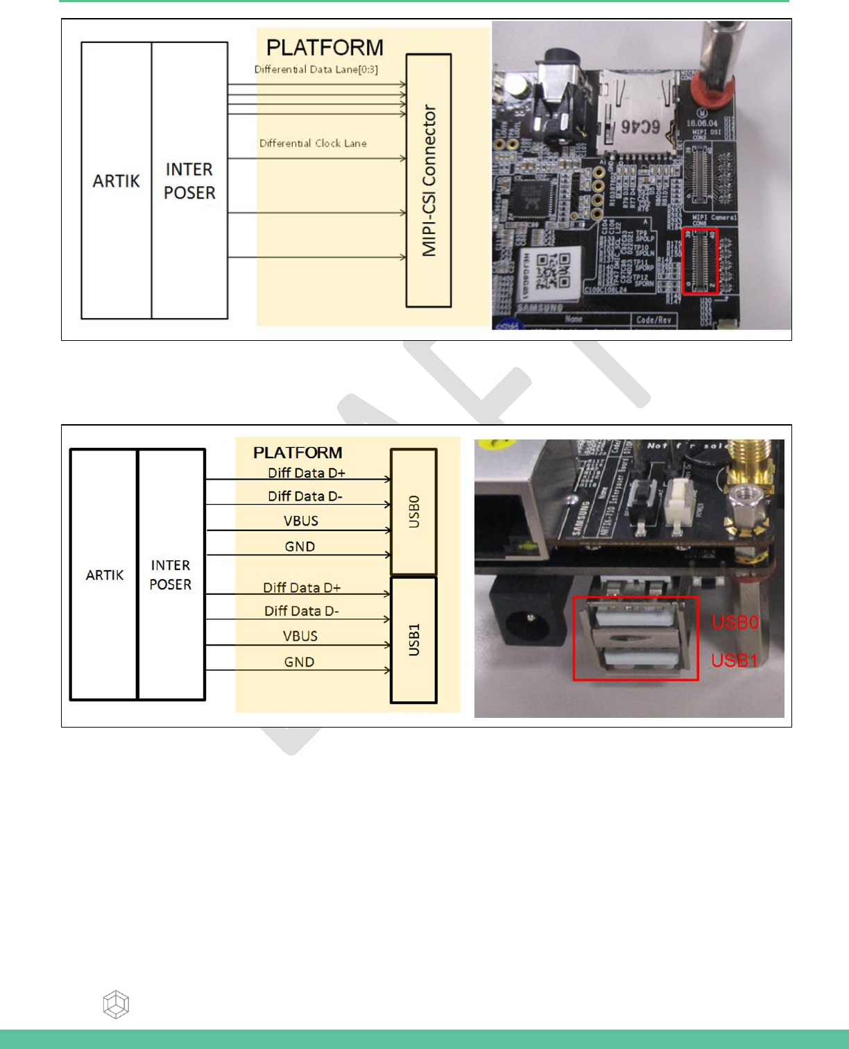
Figure 17. MIPI CSI Interface Location on the Platform Board
USB HOST 2.0 INTERFACE
The Platform board has 1x USB 2.0 Interface. The location of the USB 2.0 interface can be seen in .
Figure 18 USB2.0 Interface location on the Platform Board
Samsung Semiconductor, Inc. ARTIK 530 Development Board User Guide
Samsung Confidential
Specifications in this document are tentative and subject to
change.
20
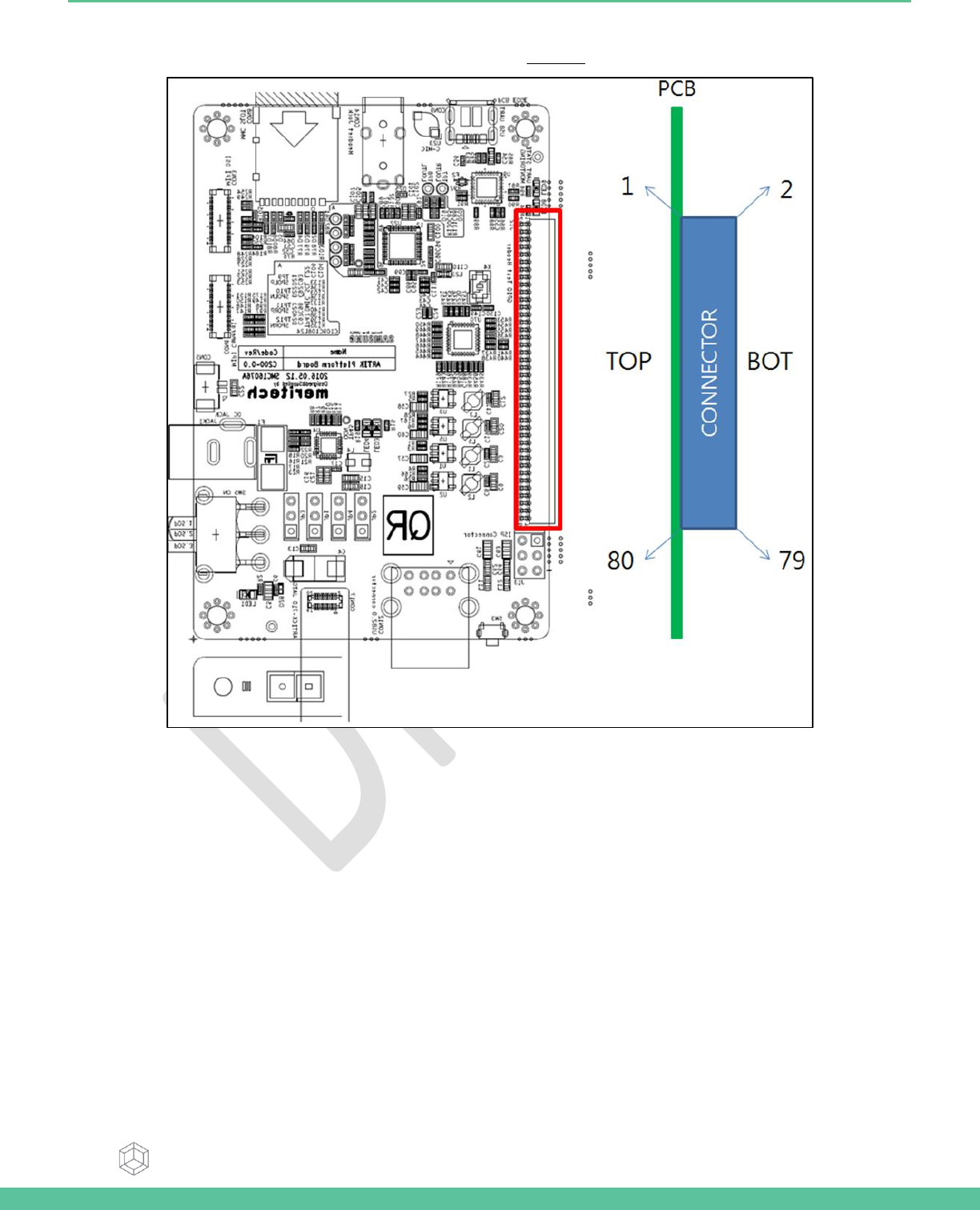
CONNECTOR TO IF BOARD INTERFACE
The Platform board has 1x expansion connector that can be seen in Figure 19. This connector enables expansion
Figure 19. Expansion Connector Interface location on the Platform Board
Samsung Semiconductor, Inc. ARTIK 530 Development Board User Guide
Samsung Confidential
Specifications in this document are tentative and subject to
change.
21
ARTIK 530 DEVELOPMENT BOARD IF BOARD
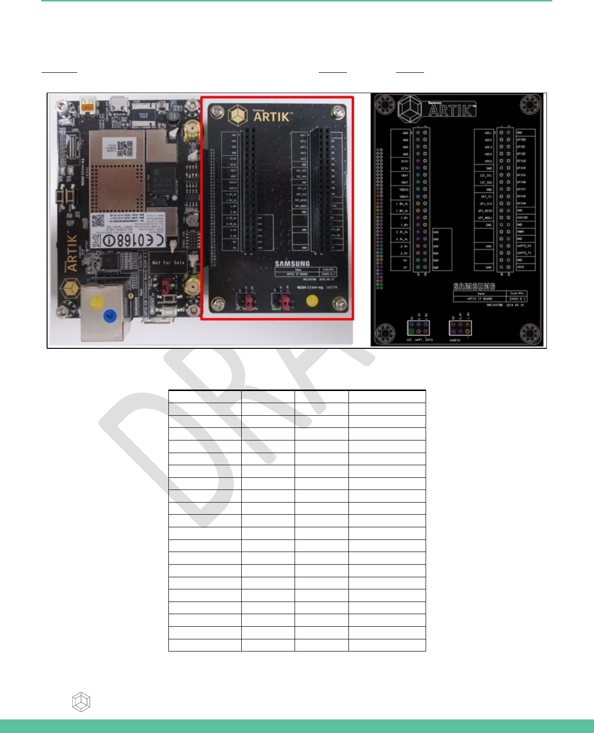
PREVIEW ON THE ARTIK IF BOARD
Figure 20 shows the highlights of the connector IF board. In addition Table 4 with J2 and Table 5 with J3 show the pinout of the
connectors with its meaning.
Figure 20. ARTIK 530 Development Board IF Board
Table 4. Connector J2
Pin Name
Pin Number
Pin Number
Pin Name
XADC1
1
2
GND
XADC2
3
4
ADD_XGPIO0
XADC3
5
6
ADD_XGPIO1
XADC4
7
8
ADD_XGPIO2
XADC5
9
10
ADD_XGPIO3
GND
11
12
ADD_XGPIO4
ADD_XI2C0_SCL
13
14
ADD_XGPIO5
ADD_XI2C0_SDA
15
16
ADD_XGPIO6
GND
17
18
ADD_XGPIO7
ADD_XSPI0_CS
19
20
ADD_XGPIO8
ADD_XSPI0_CLK
21
22
ADD_XGPIO9
ADD_XSPI0_MISO
23
24
GND
ADD_XSPI0_MOSI
25
26
ADD_XAGPIO0
GND
27
28
GND
NC
29
30
ADD_XPWM0_OUT
MICOM_GPIO1
31
32
GND
GND
33
34
ADD_XUART0_RX
NC
35
36
ADD_XUART0_TX
NC
37
38
GND
GND
39
40
XADC0
Samsung Semiconductor, Inc. ARTIK 530 Development Board User Guide
Samsung Confidential
Specifications in this document are tentative and subject to
change.
22
Table 5. Connector J3
Pin Name
Pin Number
Pin Number
Pin Name
GND
1
2
MICOM_GPIO1
GND
3
4
MICOM_GPIO2
GND
5
6
MICOM_GPIO3
GND
7
8
MICOM_GPIO4
DC5V
9
10
MICOM_GPIO5
11
12
MICOM_GPIO6
VBAT_MAIN
13
14
MICOM_GPIO7
15
16
MICOM_GPIO8
AP_VDDIO
17
18
MICOM_GPIO9
19
20
MICOM_GPIO10
VDD_EXT1P8_ALIVE
21
22
MICOM_GPIO11
23
24
MICOM_GPIO12
VDD_EXT1P8
25
26
MICOM_GPIO13
27
28
MICOM_GPIO14
VDD_EXT3P3_ALIVE
29
30
GND
31
32
GND
VDD_EXT3P3
33
34
GND
35
36
GND
VDD_EXT5P0_1
37
38
GND
39
40
GND
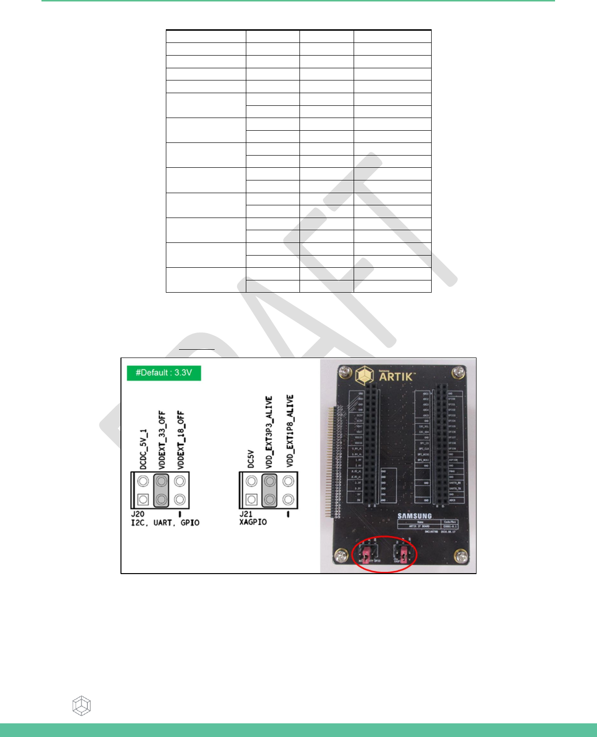
CONFIGURATION OF EXTERNAL POWER SOURCE
Through selection of the Jumpers J20 and J21 you can choose the IO power source (I2C, UART GPIO) or the XGPIO power
source of either, 1.8V, 3.3V or 5V. Figure 21 shows how to set the various jumpers to switch between power sources.
Figure 21. Jumper Interface locations J20, J21 on the IF Board
Samsung Semiconductor, Inc. ARTIK 530 Development Board User Guide
Samsung Confidential
Specifications in this document are tentative and subject to
change.
23
ARTIK 530 DEVELOPMENT BOARD BOOTING
This section will describe how to setup a connection with the ARTIK 530 Module using the Serial Port Connection and a variety
of tools.
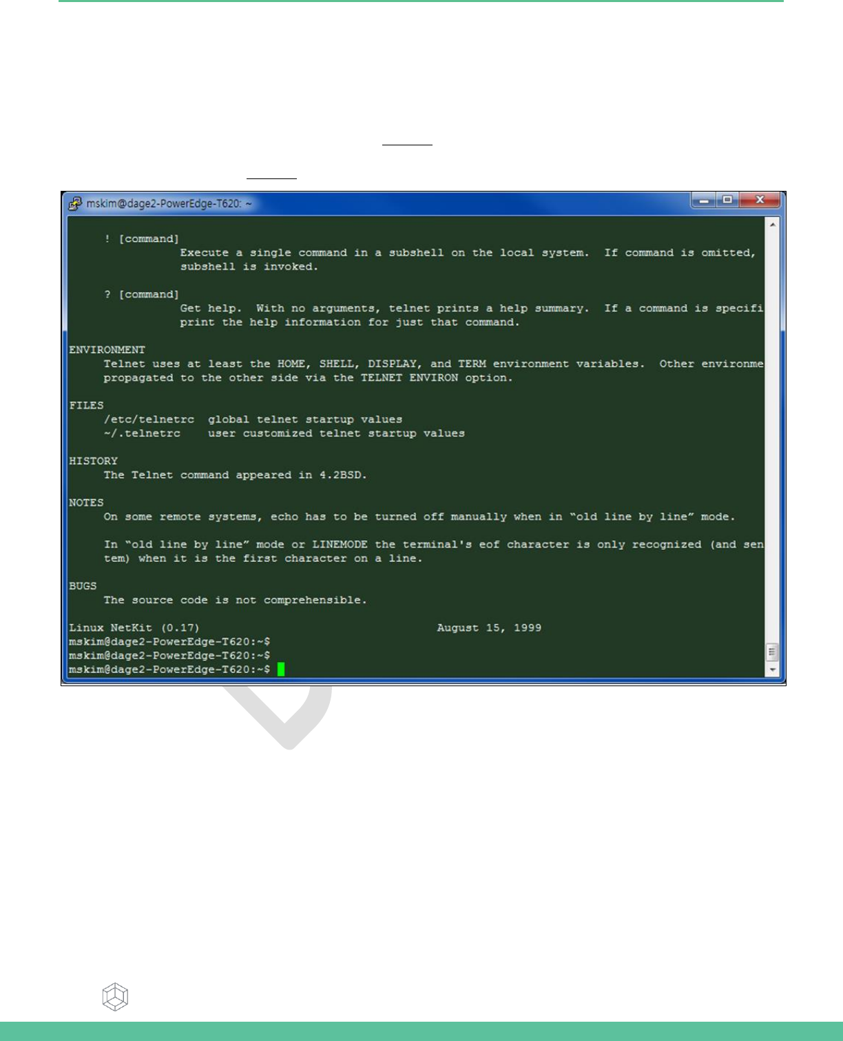
SERIAL PORT CONNECTION
You can use a typical Linux serial console as depicted in Figure 22, using the serial connector. If your PC does not have a serial
port use the USB serial cable instead. To use the serial USB cable you need to install the device driver that is associated with
your particular USB serial cable. Figure 23 depicts the USB serial cable and where it is hooked up to the Platform Board.
Figure 22. Typical Linux Serial Console
Samsung Semiconductor, Inc. ARTIK 530 Development Board User Guide
Samsung Confidential
Specifications in this document are tentative and subject to
change.
24
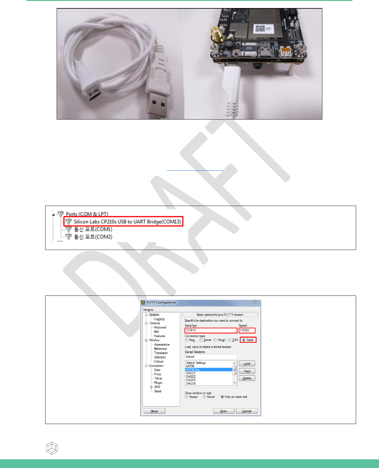
Figure 23. USB Serial Cable hooked up to the Platform Board
TERMINAL EMULATOR INSTALLATION
Setting up a connection with the ARTIK 530 Module can be done in a variety of ways. Here we choose to install PuTTY a free
serial console. The software can be downloaded from http://www.putty.org/. Once downloaded go through the following
steps:
1. Open the device manager on the control panel.
2. Check the COM port number on your PC when you connect the USB serial cable. In our case the COM port allocated
is COM13.
3. Set the PuTTY configuration as follows:
a. Set the “Serial line” as the COM port number found in step 2.
b. Set the COM speed to "115200".
c. Set the connection type to "Serial".
d. Save the session under ARTIK-Pro.
4. Select your saved session and click the “Open” button.
Samsung Semiconductor, Inc. ARTIK 530 Development Board User Guide
Samsung Confidential
Specifications in this document are tentative and subject to
change.
25
5. Power on the ARTIK 530 Development Board and hold the power button for about 1 second.
6. You should see booting messages from the ARTIK 530 Module
7. Once booting is completed you can exercise the ARTIK 530 Module using Fedora Linux commands.
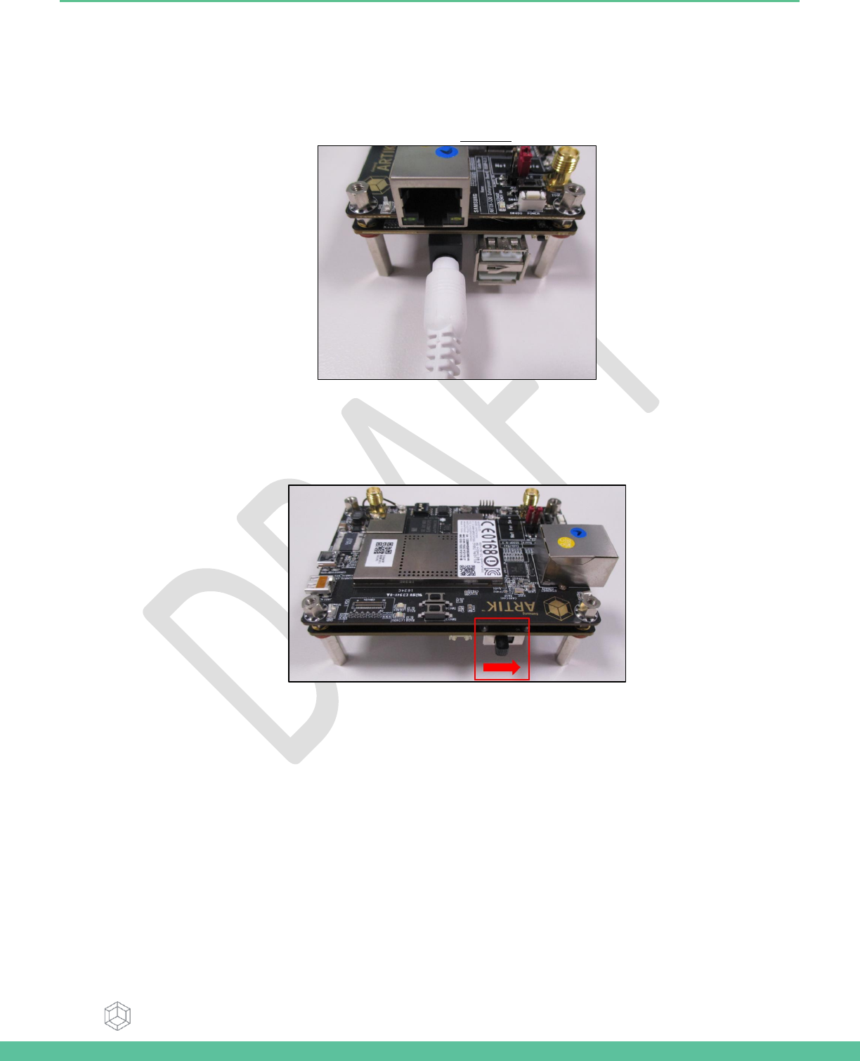
POWER ON THE ARTIK 530 DEVELOPMENT BOARD
go through the following steps:
1. Connect Power adapter and Platform board as depicted in Figure 24
Figure 24 Connection Power adaptor with development Board
2. Turn on Power switch .
Figure 25. Power switch location on the development Board
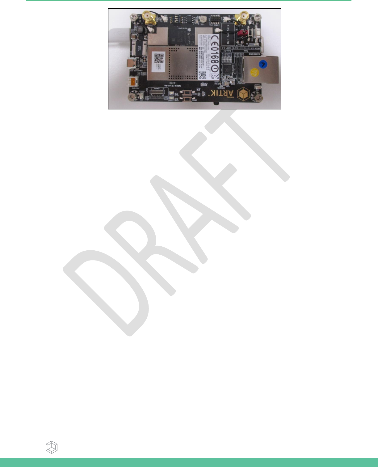
3. Hold the power button for about 1 second.
Samsung Semiconductor, Inc. ARTIK 530 Development Board User Guide
Samsung Confidential
Specifications in this document are tentative and subject to
change.
26
Figure 26. Power button location on the development Board

Samsung Semiconductor, Inc. ARTIK 530 Development Board User Guide
Samsung Confidential
Specifications in this document are tentative and subject to
change.
27
LEGAL INFORMATION
INFORMATION IN THIS DOCUMENT IS PROVIDED IN CONNECTION WITH THE SAMSUNG ARTIK™ DEVELOPMENT BOARD AND
ALL RELATED PRODUCTS, UPDATES, AND DOCUMENTATION (HEREINAFTER “SAMSUNG PRODUCTS”). NO LICENSE, EXPRESS
OR IMPLIED, BY ESTOPPEL OR OTHERWISE, TO ANY INTELLECTUAL PROPERTY RIGHTS IS GRANTED BY THIS DOCUMENT. THE
LICENSE AND OTHER TERMS AND CONDITIONS RELATED TO YOUR USE OF THE SAMSUNG PRODUCTS ARE GOVERNED
EXCLUSIVELY BY THE SAMSUNG ARTIK™ DEVELOPER LICENSE AGREEMENT THAT YOU AGREED TO WHEN YOU REGISTERED AS
A DEVELOPER TO RECEIVE THE SAMSUNG PRODUCTS. EXCEPT AS PROVIDED IN THE SAMSUNG ARTIK™ DEVELOPER LICENSE
AGREEMENT, SAMSUNG ELECTRONICS CO., LTD. AND ITS AFFILIATES (COLLECTIVELY, “SAMSUNG”) ASSUMES NO LIABILITY
WHATSOEVER, INCLUDING WITHOUT LIMITATION CONSEQUENTIAL OR INCIDENTAL DAMAGES, AND SAMSUNG DISCLAIMS
ANY EXPRESS OR IMPLIED WARRANTY, ARISING OUT OF OR RELATED TO YOUR SALE, APPLICATION AND/OR USE OF
SAMSUNG PRODUCTS INCLUDING LIABILITY OR WARRANTIES RELATED TO FITNESS FOR A PARTICULAR PURPOSE,
MERCHANTABILITY, OR INFRINGEMENT OF ANY PATENT, COPYRIGHT, OR OTHER INTELLECTUAL PROPERTY RIGHT.
SAMSUNG RESERVES THE RIGHT TO CHANGE PRODUCTS, INFORMATION, DOCUMENTATION AND SPECIFICATIONS WITHOUT
NOTICE. THIS INCLUDES MAKING CHANGES TO THIS DOCUMENTATION AT ANY TIME WITHOUT PRIOR NOTICE. THIS
DOCUMENTATION IS PROVIDED FOR REFERENCE PURPOSES ONLY, AND ALL INFORMATION DISCUSSED HEREIN IS PROVIDED
ON AN “AS IS” BASIS, WITHOUT WARRANTIES OF ANY KIND. SAMSUNG ASSUMES NO RESPONSIBILITY FOR POSSIBLE ERRORS
OR OMISSIONS, OR FOR ANY CONSEQUENCES FROM THE USE OF THE DOCUMENTATION CONTAINED HEREIN.
Samsung Products are not intended for use in medical, life support, critical care, safety equipment, or similar applications
where product failure could result in loss of life or personal or physical harm, or any military or defense application, or any
governmental procurement to which special terms or provisions may apply.
This document and all information discussed herein remain the sole and exclusive property of Samsung.
All brand names, trademarks and registered trademarks belong to their respective owners. For updates or
additional information about Samsung ARTIK™, contact the Samsung ARTIK™ team via the Samsung ARTIK™
website at www.artik.io.
Copyright © 2016 Samsung Electronics Co., Ltd.
All rights reserved. No part of this publication may be reproduced, stored in a retrieval system, or transmitted in any form or
by any means, electric or mechanical, by photocopying, recording, or otherwise, without the prior written consent of
Samsung Electronics.