Samsung Electronics Co SLS-2C40680700 Remote Radio Head User Manual LTE eNB System Description
Samsung Electronics Co Ltd Remote Radio Head LTE eNB System Description
UserManual.wiki
>
Samsung Electronics Co
>
SLS 2C40680700 User Manual
Manual
Navigation menu
Upload a User Manual
Namespaces
Wiki Guide
HTML
PDF
Info
Views
User Manual
Discussion / Help
Navigation


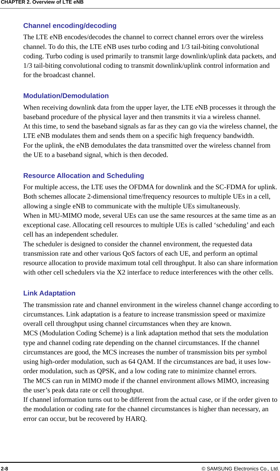

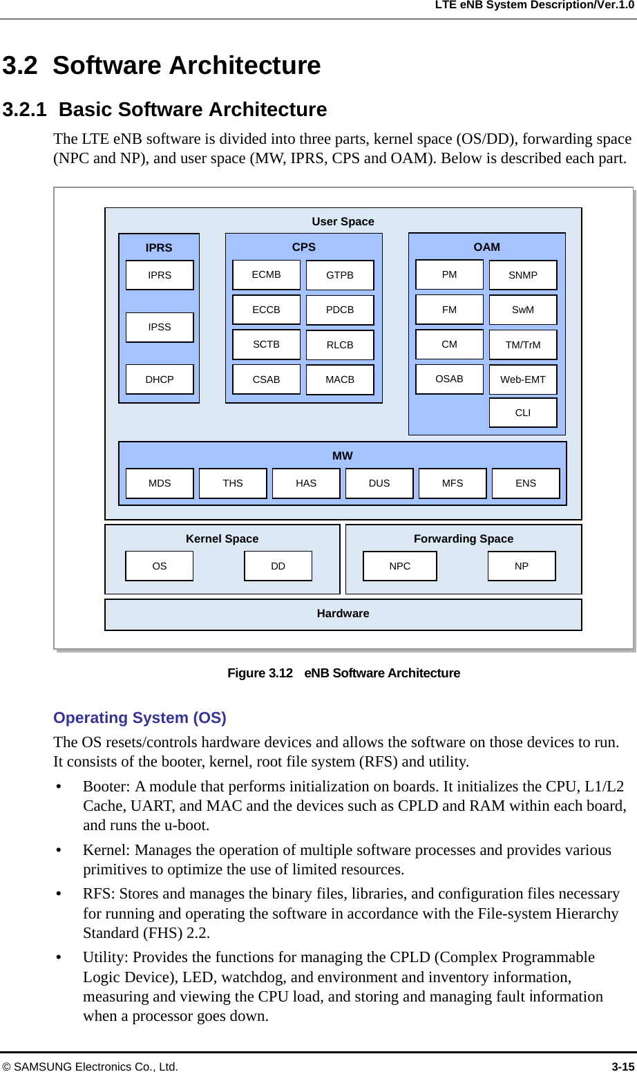
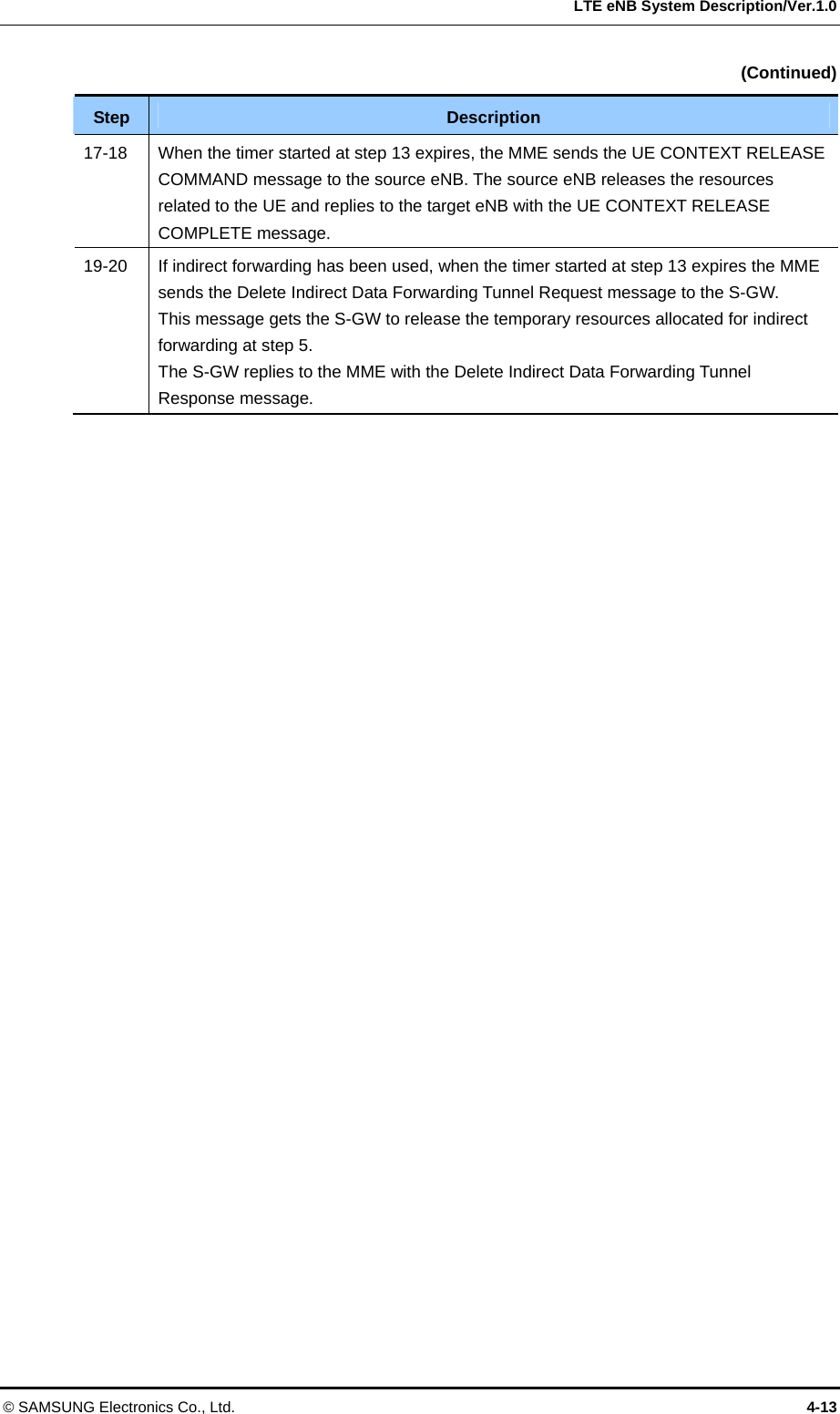
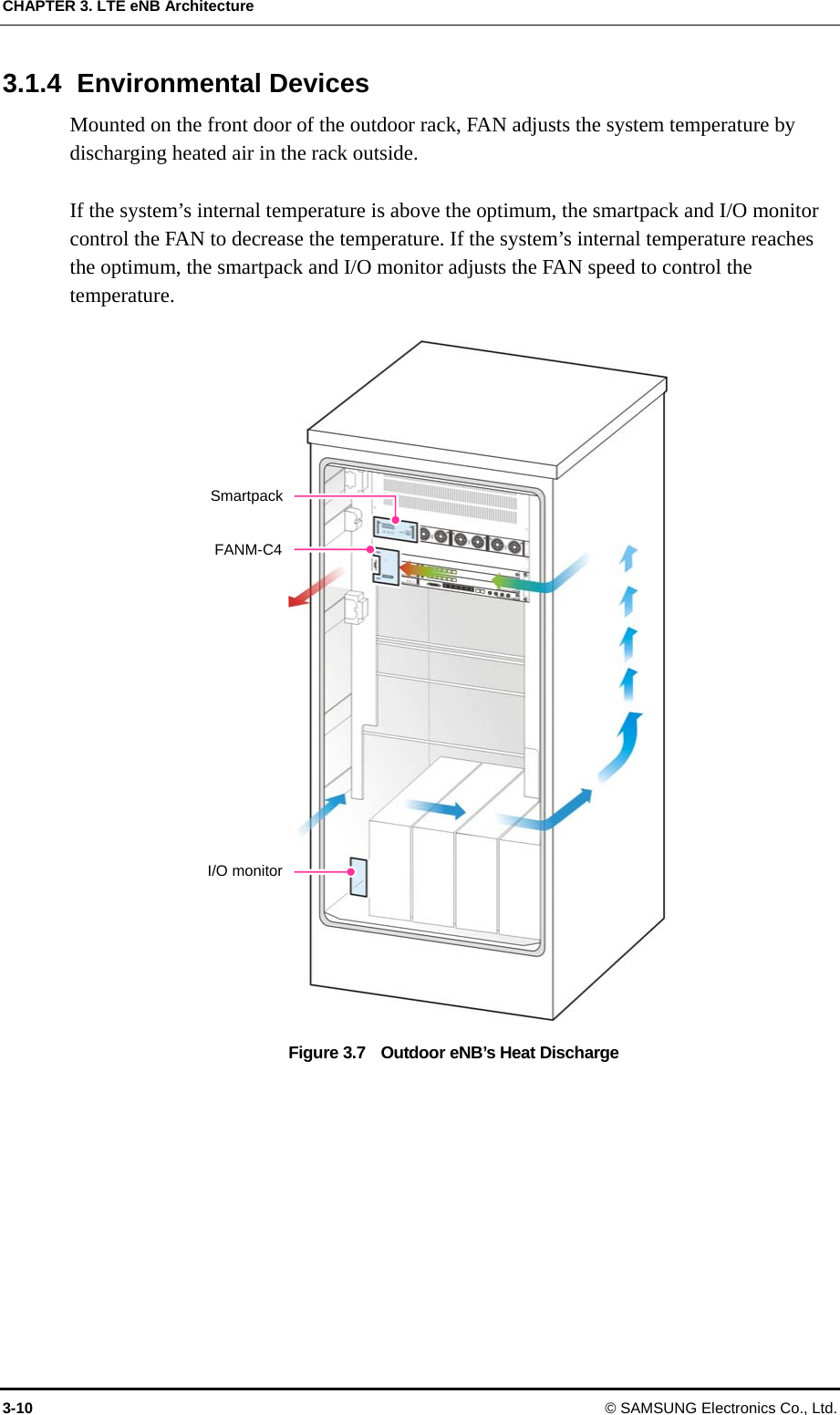
![CHAPTER 3. LTE eNB Architecture 3.1.2 L8HU The following shows the configuration of L8HU. [Top View] [Front View] [Bottom View] Figure 3.4 L8HU Configuration By default, the L8HU is installed outdoors for natural cooling. The L8HU consists of a 2Tx/4Rx RF chain as an integrated RF unit with a transceiver, power amplifier and filter installed in the single outdoor unit. It can support 10 MHz and 15 MHz bandwidth with firmware changes. In the downlink path, the L8HU performs O/E conversion for the baseband signals received from the UADU via the optic CPRI. The converted O/E signals are converted again into analog signals by the DAC. The frequency of those analog signals is up converted through the modulator and then those signals are amplified into high-power RF signals through the power amplifier. The amplified signals are sent to the antenna through the filter part. In the uplink path of the L8HU, the RF signals received through the filter part are amplified low noise in the LNA (Low Noise Amplifier) and their frequency is then down-converted through the demodulator. These down-converted frequency signals are converted to baseband signals through the ADC. The signals converted into baseband are changed to E/O through the CPRI and sent to the UADU. The control signals of the L8HU are transmitted through the control path in the CPRI. 3-6 © SAMSUNG Electronics Co., Ltd.](https://usermanual.wiki/Samsung-Electronics-Co/SLS-2C40680700/User-Guide-1504368-Page-42.png)
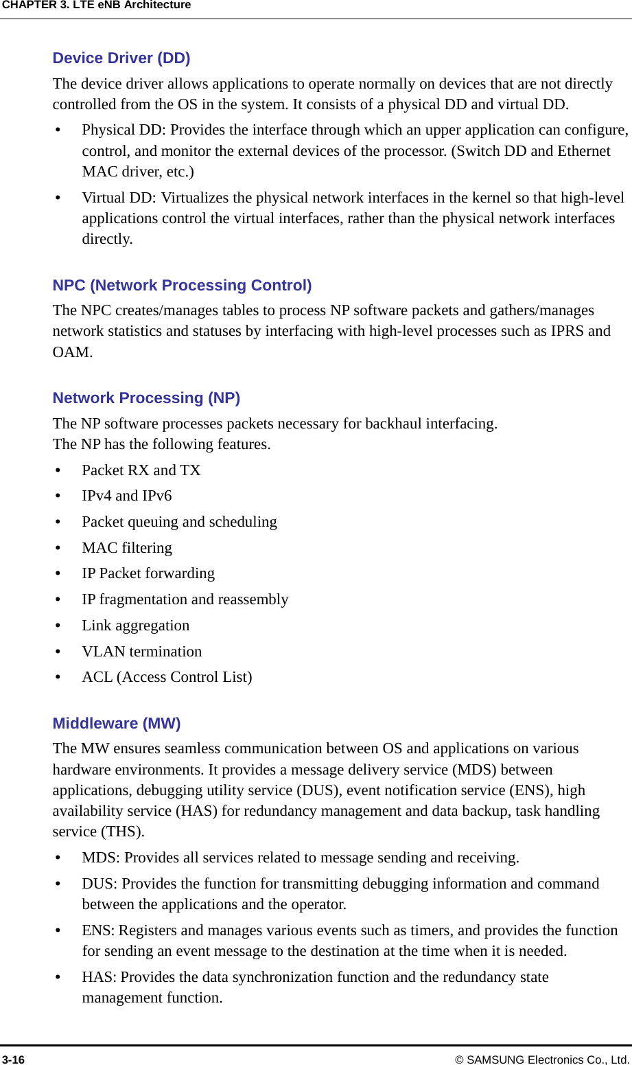
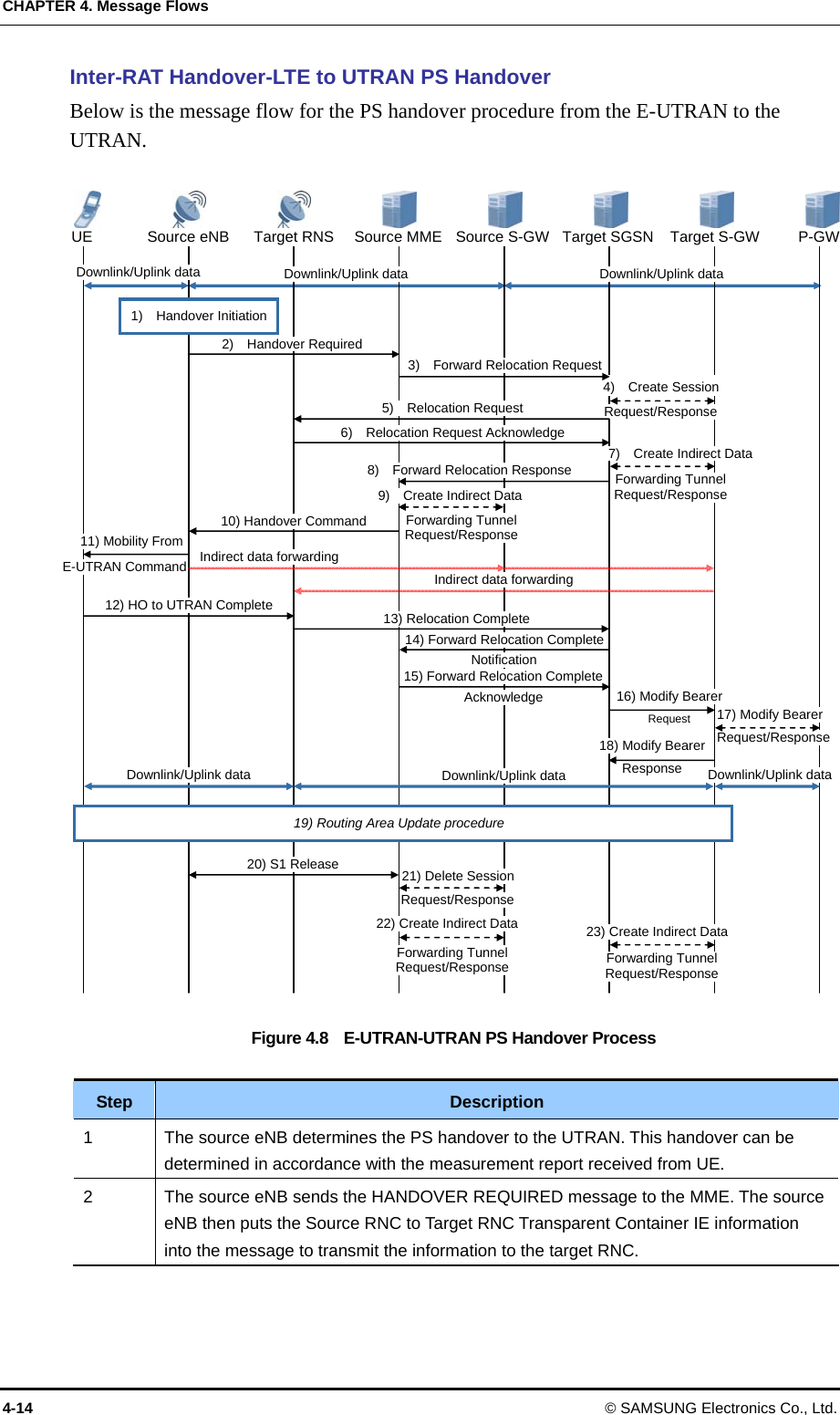
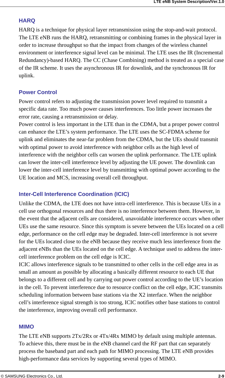
![CHAPTER 3. LTE eNB Architecture L8HU External Interface The following shows the external interfaces of L8HU. TXMON0 TXMON1 Ground TRX1 RX3TRX0 PWR OPT 0/1 RETRX2 [Bottom View] Figure 3.11 L8HU External Interface Interface Description PWR DC -48 V power input port Ground Frame Ground OPT 0/1 Optic cable terminal connected to the UADU (cable gland) RX2 RF receiving terminal #2 TXMON0 Tx signal monitoring terminal #0 TRX0 RF Tx/Rx terminal #0 RX3 RF receiving terminal #3 TXMON1 Tx signal monitoring terminal #1 TRX1 RF Tx/Rx terminal #1 RET AISG connector for remote electric tilting 3-14 © SAMSUNG Electronics Co., Ltd.](https://usermanual.wiki/Samsung-Electronics-Co/SLS-2C40680700/User-Guide-1504368-Page-50.png)