Samsung Electronics Co SLS-2C40680700 Remote Radio Head User Manual LTE eNB System Description
Samsung Electronics Co Ltd Remote Radio Head LTE eNB System Description
Manual
Ver.
LTE eNB
System Description

COPYRIGHT
This manual is proprietary to SAMSUNG Electronics Co., Ltd. and is protected by copyright.
No information contained herein may be copied, translated, transcribed or duplicated for any commercial
purposes or disclosed to the third party in any form without the prior written consent of SAMSUNG Electronics
Co., Ltd.
TRADEMARKS
Product names mentioned in this manual may be trademarks and/or registered trademarks of their respective
companies.
This manual should be read and used as a guideline for properly installing and operating the product.
This manual may be changed for the system improvement, standardization and other technical reasons without prior
notice.
If you need updated manuals or have any questions concerning the contents of the manuals, contact our Document
Center at the following address or Web site:
Address: Document Center 3rd Floor Jeong-bo-tong-sin-dong. Dong-Suwon P.O. Box 105, 416, Maetan-3dong
Yeongtong-gu, Suwon-si, Gyeonggi-do, Korea 442-600
Homepage: http://www.samsungdocs.com
©2011 SAMSUNG Electronics Co., Ltd. All rights reserved.

LTE eNB System Description
INTRODUCTION
Purpose
This manual describes the features, functions and configuration of LTE eNB.
Content and Organization
This manual consists of five Chapters and Abbreviations.
CHAPTER 1. Overview of Samsung LTE System
Introduction to Samsung LTE System
Network Configurations of Samsung LTE Network
Functional Architecture of Samsung LTE
CHAPTER 2. Overview of LTE eNB
Introduction to LTE eNB
Key Functions
Specifications
System-to-System Interfaces
CHAPTER 3. LTE eNB Architecture
Hardware Architecture
Software Architecture
CHAPTER 4. Message Flows
Call processing Message Flow
Data Message Flow
Network Synchronization Flow
Alarm Signal Flow
Loading Flow
Operation/Maintenance Message Flow
© SAMSUNG Electronics Co., Ltd. I
INTRODUCTION
CHAPTER 5. Supplementary Functions and Tools
Web-EMT
About CLI
ABBREVIATIONS
Provides explanations of the abbreviations used throughout this manual.
Conventions
The following symbols are used in this manual. The following types of paragraphs contain
special information that must be carefully read and thoroughly understood.
NOTE
This provides references for additional information.
Revision History
EDITION DATE OF ISSUE REMARKS
1.0 06. 2011. First Edition
II © SAMSUNG Electronics Co., Ltd.

LTE eNB System Description
TABLE OF CONTENTS
INTRODUCTION I
Purpose ....................................................................................................................................... I
Content and Organization............................................................................................................ I
Conventions................................................................................................................................II
Revision History.......................................................................................................................... II
CHAPTER 1. Overview of Samsung LTE System 1-1
1.1 Introduction to Samsung LTE System ................................................................................. 1-1
1.2 Samsung LTE Network Configuration.................................................................................. 1-2
1.3 LTE System Functional Architecture.................................................................................... 1-4
CHAPTER 2. Overview of LTE eNB 2-1
2.1 Introduction to LTE eNB........................................................................................................ 2-1
2.2 Key Functions........................................................................................................................ 2-7
2.2.1 Physical layer processing ........................................................................................... 2-7
2.2.2 Call Processing......................................................................................................... 2-10
2.2.3 IP Processing............................................................................................................ 2-12
2.2.4 SON.......................................................................................................................... 2-13
2.2.5 Convenient Operation and Maintenance .................................................................. 2-14
2.3 Specifications ...................................................................................................................... 2-16
2.4 System-to-System Interface................................................................................................ 2-18
2.4.1 Interface Architecture................................................................................................ 2-18
2.4.2 Protocol Stack........................................................................................................... 2-19
CHAPTER 3. LTE eNB Architecture 3-1
3.1 Hardware Architecture .......................................................................................................... 3-1
3.1.1 UADU ......................................................................................................................... 3-4
3.1.2 L8HU .......................................................................................................................... 3-6
3.1.3 Power supply .............................................................................................................. 3-8
3.1.4 Environmental Devices ............................................................................................. 3-10
© SAMSUNG Electronics Co., Ltd. III

TABLE OF CONTENTS
3.1.5 External Interface ......................................................................................................3-13
3.2 Software Architecture ..........................................................................................................3-15
3.2.1 Basic Software Architecture.......................................................................................3-15
3.2.2 CPS Block .................................................................................................................3-18
3.2.3 OAM Blocks...............................................................................................................3-21
CHAPTER 4. Message Flows 4-1
4.1 Call-Processing Message Flows...........................................................................................4-1
4.2 Data Message Flow ..............................................................................................................4-21
4.3 Network Synchronization Flow ...........................................................................................4-22
4.4 Alarm Signal Flow ................................................................................................................4-23
4.5 Loading Flow ........................................................................................................................4-24
4.6 Operation and Maintenance Message Flow .......................................................................4-25
CHAPTER 5. Supplementary Functions and Tools 5-1
5.1 Web-EMT .................................................................................................................................5-1
5.2 CLI ...........................................................................................................................................5-2
ABBREVIATION I
A ~ C ..........................................................................................................................................I
D ~ G .........................................................................................................................................II
H ~ M ........................................................................................................................................III
N ~ Q ....................................................................................................................................... IV
R ~ T ........................................................................................................................................ V
U ~ W ....................................................................................................................................... VI
IV © SAMSUNG Electronics Co., Ltd.

LTE eNB System Description/Ver.1.0
LIST OF FIGURES
Figure 1.1 Samsung LTE Network Configurations.................................................................. 1-2
Figure 1.2 Functions of E-UTRAN and EPC........................................................................... 1-4
Figure 2.1 Indoor eNB + L8HU Installation............................................................................. 2-2
Figure 2.2 Outdoor eNB + L8HU Installation .......................................................................... 2-3
Figure 2.3 LTE eNB System Interface Architecture .............................................................. 2-18
Figure 2.4 UE eNB Protocol Stack ....................................................................................... 2-19
Figure 2.5 eNB S-GW User Plane Protocol Stacks.......................................................... 2-20
Figure 2.6 eNB MME Control Plane Protocol Stacks....................................................... 2-20
Figure 2.7 eNB eNB User Plane Protocol Stacks ........................................................... 2-21
Figure 2.8 eNB eNB Control Plane Protocol Stacks ........................................................ 2-21
Figure 2.9 eNB LSM Interface Protocol Stacks............................................................... 2-22
Figure 3.1 Removable eNB’s Internal Configuration .............................................................. 3-2
Figure 3.2 Outdoor eNB Configuration ................................................................................... 3-3
Figure 3.3 Configuration......................................................................................................... 3-4
Figure 3.4 L8HU Configuration............................................................................................... 3-6
Figure 3.5 Power Supply........................................................................................................ 3-8
Figure 3.6 Power Diagram ..................................................................................................... 3-9
Figure 3.7 Outdoor eNB’s Heat Discharge ........................................................................... 3-10
Figure 3.8 UADU Heat-Discharge Mechanism......................................................................3-11
Figure 3.9 Sensors............................................................................................................... 3-12
Figure 3.10 UADU External Interface................................................................................... 3-13
Figure 3.11 L8HU External Interface .................................................................................... 3-14
Figure 3.12 eNB Software Architecture ................................................................................ 3-15
Figure 3.13 CPS Architecture............................................................................................... 3-18
Figure 4.1 Attach Process ...................................................................................................... 4-2
Figure 4.2 Service Request Process by UE ........................................................................... 4-4
Figure 4.3 Service Request Process by Networking .............................................................. 4-5
Figure 4.4 Detach Process by UE .......................................................................................... 4-6
Figure 4.5 Detach Process by MME....................................................................................... 4-8
Figure 4.6 X2-based Handover Process ................................................................................ 4-9
Figure 4.7 S1-based Handover Process ...............................................................................4-11
Figure 4.8 E-UTRAN-UTRAN PS Handover Process........................................................... 4-14
Figure 4.9 UTRAN-E-UTRAN PS Handover Process........................................................... 4-16
Figure 4.10 CS Fallback to UTRAN Process (UE in Active Mode, No PS HO Support)....... 4-18
Figure 4.11 CS Fallback to GERAN Process (UE in Active Mode, No PS HO Support)....... 4-19
© SAMSUNG Electronics Co., Ltd. V

TABLE OF CONTENTS
VI © SAMSUNG Electronics Co., Ltd.
Figure 4.12 eNB System Control and Traffic Flow ................................................................4-21
Figure 4.13 eNB Network Synchronization Flow...................................................................4-22
Figure 4.14 eNB System Alarm Flow ....................................................................................4-23
Figure 4.15 Loading Signal Flow...........................................................................................4-24
Figure 4.16 Operation and Maintenance Signal Flow ...........................................................4-25
Figure 5.1 Web-EMT Interface................................................................................................5-1

LTE eNB System Description
CHAPTER 1. Overview of Samsung
LTE System
1.1 Introduction to Samsung LTE System
The Samsung LTE system is a wireless network system supporting 3GPP Long Term
Evolution (3GPP LTE; hereafter, LTE) based services. It improved the disadvantages of
low transmission speed and the high cost of the data services provided by the existing
3GPP mobile communication system. The Samsung LTE system is a next generation
wireless network system that can provide high-speed data services at a low cost regardless
of time and location.
The Samsung LTE system supports the downlink Orthogonal Frequency Division Multiple
Access (OFDMA) transmission technology and the uplink Single Carrier (SC) FDMA
transmission technology in Frequency Division Duplex (FDD) mode, and supports a
scalable bandwidth for supporting various spectrum allocations to provide high-speed data
services. In addition, system performance and capacity have increased as a result of high-
performance hardware; the Samsung LTE system can easily accommodate a variety of
functions and services.
The Samsung LTE system consists of the evolved UTRAN Node B (eNB), Evolved Packet
Core (EPC), and LTE System Manager (LSM). The eNB is a system between the UE and
EPC, and processes packet calls by connecting to the User Equipment (UE) wirelessly in
accordance with the LTE Air standards. The EPC is between the eNB and the Packet Data
Network (PDN), and performs various control functions. The EPC consists of the Mobility
Management Entity (MME), the Serving Gateway (S-GW), and PDN Gateway (P-GW).
The LSM also provides an interface with an operator, functions to manage software,
configurations, performance, and failures as well as an ability to act as a Self-Organizing
Network (SON) server.
Supported System Specifications
The Samsung LTE system is based on the Rel-8 and Rel-9 standards of the LTE
3rd Generation Partnership Project (3GPP).
© SAMSUNG Electronics Co., Ltd. 1-1
CHAPTER 1. Overview of Samsung LTE System
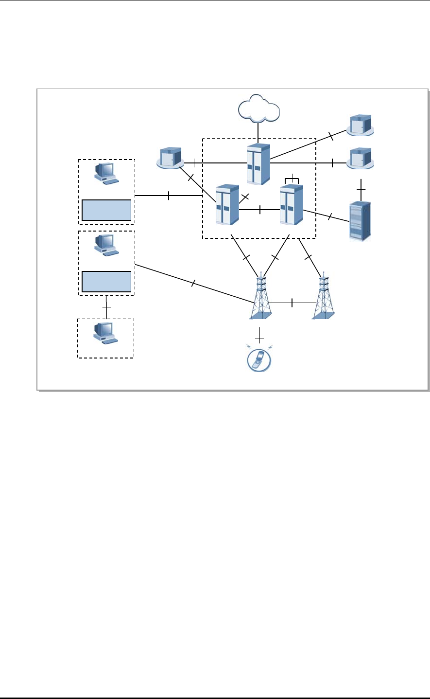
1.2 Samsung LTE Network Configuration
The Samsung LTE system consists of eNB, LSM, and EPC (MME, S-GW, P-GW), and its
network configurations are shown below.
RMI
MSS
EMS
ESM
EPC
P-GW
OCS
PCRF
OFCS
eNB eNB
PDN
MME S-GW
LSM
EMS
TL1
Sp
Gx
Gy
S10
Gz
Gz
Uu
X2-C
X2-U
S1
S1-
MME
S1-U
S5/S8
S11
S6a
HSS
UE
SNMP/FTP/UDP
Figure 1.1 Samsung LTE Network Configurations
evolved UTRAN Node-B (eNB)
The eNB is located between the UE and EPC. It processes packet calls by connecting to the
UE wirelessly according to the LTE Air standard. The eNB performs functionalities such as
transmission and receipt of wireless signals, modulation and demodulation of packet traffic
signals, packet scheduling for efficient utilization of wireless resources, Hybrid Automatic
Repeat Request (HARQ)/ARQ processing, Packet Data Convergence Protocol (PDCP) for
packet header compression, and wireless resources control.
It also performs handovers interoperating with the EPC.
Evolved Packet Core (EPC)
The EPC is a system between the eNB and PDN, consisting of the MME, S-GW and P-GW.
The MME processes control messages through the eNB and the NAS signaling protocol,
and processes the control functions for the control plane, such as mobility management,
tracking area list management, and bearer and session management for UEs.
The S-GW carries out the anchor function in the user plane between the 2G/3G access
system and the LTE system, and manages the packet transport layer for downlink/uplink data.
1-2 © SAMSUNG Electronics Co., Ltd.

LTE eNB System Description/Ver.1.0
The P-GW allocates an IP address to the UE. For mobility between the LTE system and the
non-3GPP access system, the P-GW carries out the anchor function and manages the
charging and transmission rate according to the service level.
LTE System Manager (LSM)
The LSM provides an interface to perform operations and maintenance on the eNB by the
operator, functions to manage software, configurations, performance, and failures as well
as an ability to act as a Self-Organizing Network (SON) server.
EPC System Manager (ESM)
The ESM provides the user interface for the operator to run and maintain the MME, S-GW,
and P-GW as system management activities.
Master SON Server (MSS)
The MSS interoperates with the local SON server as its higher node, performing the
optimized interoperation for the multi-LSM. The MSS can work with OSS (Operating
Support System) of the service provider who can decide whether to link them.
Home Subscriber Server (HSS)
The HSS is a database management system that stores and manages the parameters and
location information for all registered mobile subscribers. The HSS manages key data such
as the mobile subscriber’s access capability, basic services and supplementary services, and
provides a routing function to the subscribed receivers.
Policy and Charging Rule Function (PCRF)
The PCRF creates policy rules to dynamically apply the QoS (Quality of Service) and
accounting policies differentiated by service flow, or creates the policy rules that can be
applied commonly to multiple service flows. The IP edge includes the PCEF (Policy and
Charging Enforcement Function), which allows implementation of policy rules sent from
the PCRF per service flow.
Online Charging System (OCS)
The OCS sends/receives charging information required for a subscriber’s online charging
during calls.
Offline Charging System (OFCS)
The OFCS stores offline charging data and provides subscriber charging information.
© SAMSUNG Electronics Co., Ltd. 1-3
CHAPTER 1. Overview of Samsung LTE System
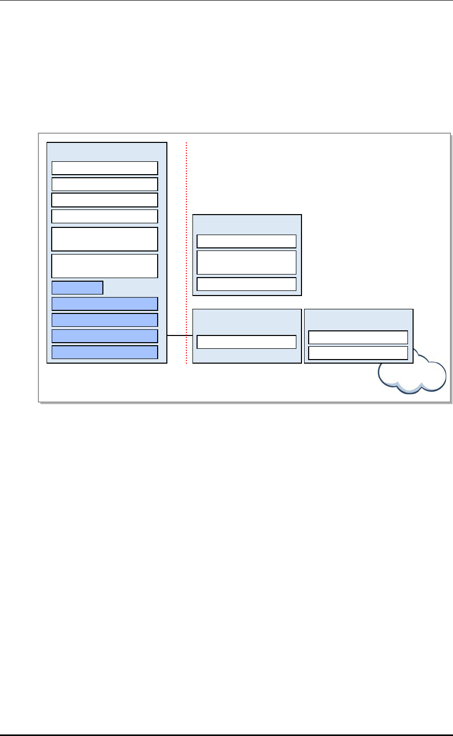
1.3 LTE System Functional Architecture
The eNB manages UEs, which are in connected mode, at the AS (Access Stratum) level.
The MME manages UEs, which are in idle mode, at the NAS (Non-Access Stratum) level,
and the P-GW manages user data at the NAS level as well as working with other networks.
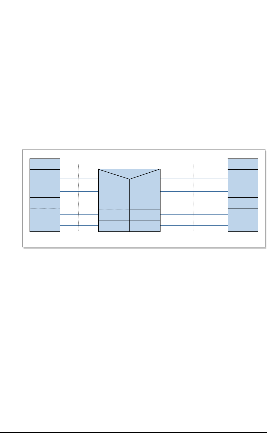
The functional architecture of E-UTRAN eNB, MME, S-GW, and P-GW according to the
3GPP standards is shown below. The eNB is structured in layers while the EPC is not.
E-UTRAN
PHY
MAC
RLC
PDCP
RRC
Dynamic Resource
Allocation (Scheduler)
eNB Measurement
Configuration & Provision
Radio Admission Control
Connection Mobility Control
RB Control
Inter Cell RRM
eNB
S1
MME
NAS Security
Idle State Mobility
Handling
EPS Bearer Control
S-GW
Mobility Anchoring
P-GW
Packet Filtering
UE IP address allocation
EPC Internet
Figure 1.2 Functions of E-UTRAN and EPC
eNB
The eNB serves the E-UTRAN (Evolved UTRAN), a wireless access network in the LTE
system.
The eNBs are connected through the X2 interface whereas the eNB and EPC are connected
through S1 interface.
The eNB’s wireless protocol layers are divided into Layer 2 and Layer 3. Layer 2 is
subdivided into the MAC (Media Access Control) layer, RLC (Radio Link Control) layer,
and PDCP layer, each operating independently. Layer3 has the RRC layer.
The MAC layer distributes wireless resources to each bearer according to its priority, and
carries out the multiplexing function and the HARQ function for the data received from the
multiple upper logical channels.
The RLC layer carries out the following functions.
Reconstructs the data received from the PDCP layer in accordance with the size
specified by the MAC layer (segmentation and reassembly).
When data transmission fails in the lower layer, requests retransmission to recover
them (ARQ).
Reorders the data recovered by performing HARQ in the MAC layer.
1-4 © SAMSUNG Electronics Co., Ltd.

LTE eNB System Description/Ver.1.0
The PDCP layer carries out the following functions.
Compresses and decompresses headers
Encrypts and decrypts the user plane and control plane data
Protects and verifies data integrity of the control plane
Transmits data and manages serial numbers
Removes data based on a timer as well as removing duplicates
The RRC layer is responsible for managing mobility in the wireless access network,
keeping and controlling the RB (Radio Bearer), managing RRC connections, and sending
system information.
Mobility Management Entity (MME)
The MME works with the E-UTRAN (eNB), handling S1-AP (S1 Application Protocol)
signaling messages in the SCTP (Stream Control Transmission Protocol) base to control
call connections between the MME and eNB as well as handling NAS signaling messages
in the SCTP base to control mobility and call connections between the UE and EPC.
The MME also works with the HSS to obtain, modify and authenticate subscriber
information, and works with the S-GW to request assignment, release and modification of
bearer paths for data routing and forwarding using the GTP-C protocol.
The MME can work with the 2G and 3G systems, SGSN, and MSC to provide mobility,
HO (Handover), CS (Circuit Service) fallback, and SMS (Short Message Service) services.
The MME is also responsible for managing mobility between eNBs, idle-mode UE
reachability, TA (Tracking Area) list as well as for P-GW/S-GW selection, authentication,
and bearer management.
MME supports the handover between MMEs and provides the mobility for the handover
between the eNBs.
It also supports the SGSN selection function upon handover to a 2G or 3G 3GPP network.
Serving Gateway (S-GW)
The S-GW carries out the mobility anchor function upon inter-eNB handover and inter-
3GPP handover, and processes routing and forwarding of packet data. The S-GW allows
the operator to set a different charging policy by UE, PDN or QCI, and manages the packet
transport layer for uplink/downlink data. The S-GW also works with the MME, P-GW, and
SGSN to support the GTP (GPRS Tunneling Protocol) and PMIP (Proxy Mobile IP).
PDN Gateway (P-GW)
The P-GW works with PCRF to carry out charging and bearer policies, and manage the
charging and transmission rate based on the service level. It also provides packet filtering
per subscriber, assigns IP addresses to UEs, and manages the packet transmission layer of
the downlink data.
© SAMSUNG Electronics Co., Ltd. 1-5

CHAPTER 1. Overview of Samsung LTE System
This page is intentionally left blank.
1-6 © SAMSUNG Electronics Co., Ltd.

LTE eNB System Description
CHAPTER 2. Overview of LTE eNB
2.1 Introduction to LTE eNB
The LTE eNB system is located between the UE and EPC, and interfaces via a wireless
connection according to the LTE Air Interface, providing subscribers with wireless
communication services. The eNB engages in sending and receiving radio signals with the
UE, and handling traffic modulation/demodulation signals. The LTE eNB is also
responsible for packet scheduling and wireless bandwidth allocation as well as for
handovers by interfacing with the EPC.
It consists of a DU (Digital Unit), i.e., UADU (Universal platform type A Digital Unit) and
a RU (Radio Unit), i.e., L8HU (LTE eNB remote radio Head Unit).
The UADU is a 19 inch shelf-type digital unit and can be mounted on a 19 inch rack in an
indoor/ outdoor environment.
The L8HU is an RF integration module consisting of a transceiver, power amplifier, and
filter. It sends and receives traffic, clock information, and alarm/control messages to and
from the L9CA. The L8HU has a 2Tx/4Rx structure with optic CPRI support, and can be
installed on a wall or pole in an outdoor environment.
© SAMSUNG Electronics Co., Ltd. 2-1
CHAPTER 2. Overview of LTE eNB
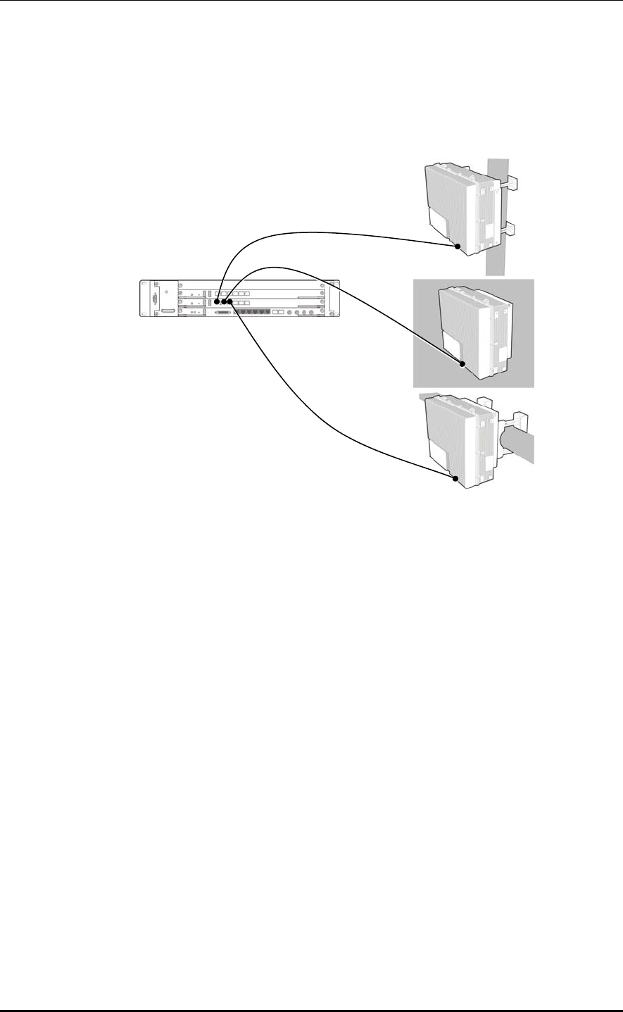
The LTE eNB can be installed as shown below:
Indoor eNB + L8HU
The L9CA from the UADU mounted on an indoor 19 inch rack is connected to the L8HU.
The L8HU can be installed on a wall or pole.
Figure 2.1 Indoor eNB + L8HU Installation
2-2 © SAMSUNG Electronics Co., Ltd.
LTE eNB System Description/Ver.1.0
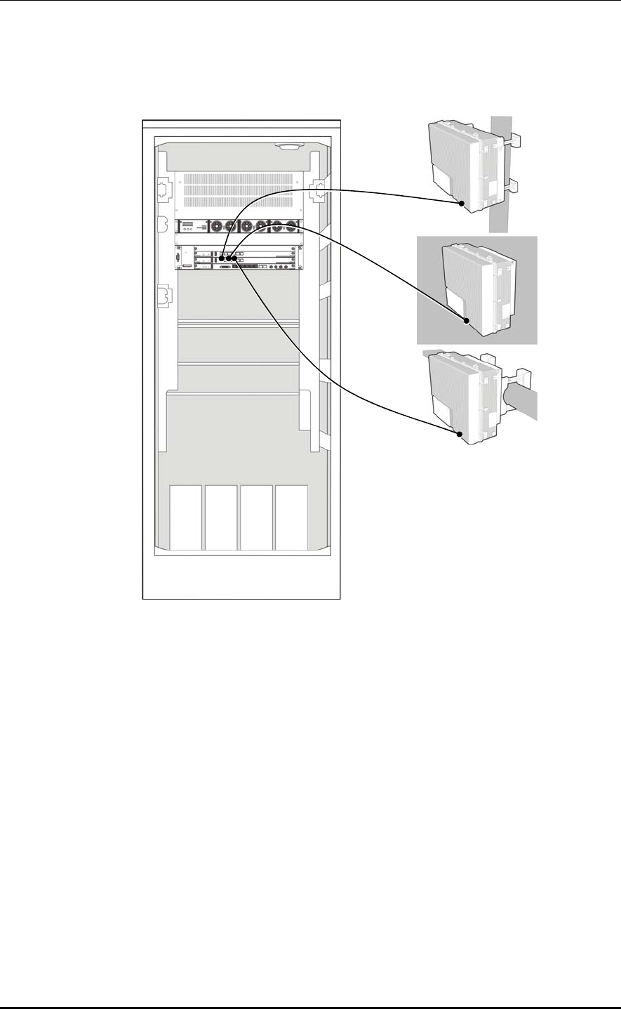
Outdoor eNB + L8HU
The L9CA from the UADU mounted on an outdoor rack is connected to the L8HU.
The L8HU can be installed on a wall or pole.
Figure 2.2 Outdoor eNB + L8HU Installation
© SAMSUNG Electronics Co., Ltd. 2-3

CHAPTER 2. Overview of LTE eNB
The LTE eNB system has the following key features:
High Compatibility and Interoperability
Samsung LTE system adheres to specifications released in accordance with the 3GPP
standards, providing excellent compatibility and interoperability.
High-Performance Modular Structure
The LTE eNB system uses a high-performance processor and has a modular structure that
allows an easy hardware and software upgrade.
Support for Advanced RF and Antenna Solutions
The LTE eNB system adopted a power amplifier to support bandwidth for broadband
operation, and also supports MIMO (Multiple Input Multiple Output).
Maintenance with Enhanced Security
The LTE eNB system provides security functions (SNMPv2c, SSH, FTP/SFTP, and
HTTPs) for all channels for operation and maintenance. It authenticates operators accessing
the system, grants them permissions, and stores their system execution histories as logs.
6Rx Multi Antenna Support
Compared to generic eNBs with 2Rx antennas that receive 2Rx in one sector, Samsung
LTE eNB has enhanced reception, receiving antenna signals up to 6Rx from its own sector
as well as from the repeater mode.
OFDMA/SC-FDMA Scheme
The LTE eNB performs the downlink OFDMA/uplink SC-FDMA (Single Carrier
Frequency Division Multiple Access) channel processing that supports the standard LTE
physical layer.
The downlink OFDMA allows the system to transmit data to multiple users simultaneously
using the subcarrier allocated to each user. Depending on the channel status and the
transmission rate requested by the user, the downlink OFDM can allocate one or more
subcarriers to a specific subscriber to transmit data. Moreover, when all subcarriers are
divided for multiple users, the FDMA can select and assign to each subscriber a subcarrier
with the most appropriate features, distributing resources efficiently and increasing data
throughput.
The uplink SC-FDMA, which is similar to the modulation/demodulation method of the
OFDMA, minimizes the PAPR (Peak-to-Average Power Ratio) of the transmitter by
computing, for each user, DFT (Discrete Fourier Transform) during modulation at the
transmitting end, and IDFT (Inverse Discrete Fourier Transform) during demodulation at
the receiving end, and continuously assigns frequency resources to users. As a result, it
saves the UE’s power.
2-4 © SAMSUNG Electronics Co., Ltd.

LTE eNB System Description/Ver.1.0
Support for Multiple System Configurations
The LTE eNB supports multiple system and network configurations with a digital unit
(UADU) and radio unit (RRH: Remote Radio Head). The digital I/Q and C & M (Control &
Maintenance) interface based on the CPRI (Common Public Radio Interface) standard is
used between the DU and RU to send and receive data traffic signals and OAM
information, and uses optic cable physically.
The UADU and L8HU each have a power supply of DC -48 V.
Multiple Configurations for Network Operation
The LTE eNB supports multiple configurations including RRH (L8HU).
The RRH is highly flexible in its installation, and helps with setting up a network in a
variety of configurations depending on the location and operation method.
Easy Installation
The optic interface component that interfaces with the UADU and the RF signal
processing component is integrated into the RRH, which becomes a very small and
very light single unit. The L8HU can be installed on a wall or pole.
Moreover, as the distance between the RRH and antenna is minimized, the loss of RF
signals due to the antenna feeder line can be reduced so that the line can provide more
enhanced RF receiving performance than the existing rack-type eNB.
Natural Cooling
Because the RRH is installed outdoors and has an efficient design, it can radiate heat
efficiently without any additional cooling system. No additional maintenance cost is
needed for cooling the RRH.
Loopback Test
The LTE eNB provides the loopback test function to check whether communication is
normal on the Digital I/Q and C & M interface line between the DU and RU.
Remote Firmware Downloading
Operators can upgrade the L8HU and its service by replacing its firmware.
They can download firmware to the L8HU remotely using a simple command from the
LSM without visiting field stations.
As a result, the number of visits is minimized, leading to reduced maintenance costs
and system operation with ease.
Monitoring Port
Operators can monitor the information for an L8HU using its debug port.
MIMO Support
The LTE eNB supports 2Tx/2Rx or 4Tx/4Rx MIMO by default using multiple antennas.
MIMO has the following techniques.
SFBC (Space Frequency Block Coding)-Downlink
Reliability for the links is increased. (Note that the peak data rate is not increased.)
This technology implements Space Time Block Coding (STBC) not on time but on
frequency.
For 2 Tx: The method similar to STBC (Alamouti codes) is used.
For 4 Tx: Both the SFBC and Frequency Switched Transmit Diversity (FSTD) are
used simultaneously.
© SAMSUNG Electronics Co., Ltd. 2-5

CHAPTER 2. Overview of LTE eNB
SM (Spatial Multiplexing)-Downlink
This technology can increase the peak data rate by dividing and sending other data
via multiple antenna paths. (Each path uses the same time/frequency resource.)
SU (Single User)-MIMO: SM between the eNB and single UE, it increases the
UE’s peak data rate.
MU (Multi-User)-MIMO: SM between the eNB and multiple UEs; it increases cell
throughput instead of the UE peak data rate.
Open-loop SM: Runs without the UE’s PMI (Precoding Matrix Indicator) feedback
when the channel changes quickly or is unknown due to the UE’s fast mobility.
Closed-loop SM: Runs with the UE’s PMI feedback received from the eNB when
there is channel information due to the UE’s slow mobility.
UL (Uplink) Transmit Antenna Selection-Uplink
The UE uses one RF chain and 2Tx antennas. The eNB informs the UE which Tx
antenna to use.
Closed-loop selection of Tx antenna
MU (Multi-User) MIMO or Collaborative MIMO-Uplink
SM in which two UEs use the same time/frequency resources in the UL
simultaneously to transmit different data.
Each UE uses a single Tx antenna.
The eNB selects two orthogonal UEs.
There is an increase in overall cell throughput, but not in each UE’s peak data rate.
2-6 © SAMSUNG Electronics Co., Ltd.

LTE eNB System Description/Ver.1.0
2.2 Key Functions
Samsung LTE eNB has the following key features.
Physical layer processing
Call processing
IP processing
SON
Convenient operation and maintenance
2.2.1 Physical layer processing
The LTE eNB sends/receives data via wireless channels between the eNB and UE.
The eNB handles the following:
Downlink reference signal generation/transmission
Downlink synchronization signal generation/transmission
Channel encoding/decoding
Modulation/demodulation
Resource allocation and scheduling
Link adaptation
HARQ
Power control
ICIC
MIMO
Downlink reference signal generation/transmission
The reference signal is used to demodulate downlink signals in the UE, and to measure the
characteristics of the channel for scheduling, link adaptation, and handover.
Cell-specific and UE-specific reference signals are used when transmitting non-MBSFN.
The cell-specific reference signal is used to measure the quality of the channel, calculate
the MIMO rank, perform MIMO precoding matrix selection, and measure the strength of
the signals for handover. To operate MIMO, a different reference signal is sent for each
antenna path.
Downlink Synchronization Signal Generation/Transmission
The synchronization signal is used to perform the initial synchronization when the UE
starts to communicate with the base station. It can be PSS (Primary Synchronization
Signal) or SSS (Secondary Synchronization Signal). The UE obtains cell identify through
the synchronization signal, and other cell information through the broadcast channel.
Transmission in the synchronization signal and broadcast channel occurs at 1.08 MHz of
the cell’s channel bandwidth as the UE can identify cell ID and other basic information
regardless of the eNB’s transmission bandwidth.
© SAMSUNG Electronics Co., Ltd. 2-7

CHAPTER 2. Overview of LTE eNB
Channel encoding/decoding
The LTE eNB encodes/decodes the channel to correct channel errors over the wireless
channel. To do this, the LTE eNB uses turbo coding and 1/3 tail-biting convolutional
coding. Turbo coding is used primarily to transmit large downlink/uplink data packets, and
1/3 tail-biting convolutional coding to transmit downlink/uplink control information and
for the broadcast channel.
Modulation/Demodulation
When receiving downlink data from the upper layer, the LTE eNB processes it through the
baseband procedure of the physical layer and then transmits it via a wireless channel.
At this time, to send the baseband signals as far as they can go via the wireless channel, the
LTE eNB modulates them and sends them on a specific high frequency bandwidth.
For the uplink, the eNB demodulates the data transmitted over the wireless channel from
the UE to a baseband signal, which is then decoded.
Resource Allocation and Scheduling
For multiple access, the LTE uses the OFDMA for downlink and the SC-FDMA for uplink.
Both schemes allocate 2-dimensional time/frequency resources to multiple UEs in a cell,
allowing a single eNB to communicate with the multiple UEs simultaneously.
When in MU-MIMO mode, several UEs can use the same resources at the same time as an
exceptional case. Allocating cell resources to multiple UEs is called ‘scheduling’ and each
cell has an independent scheduler.
The scheduler is designed to consider the channel environment, the requested data
transmission rate and other various QoS factors of each UE, and perform an optimal
resource allocation to provide maximum total cell throughput. It also can share information
with other cell schedulers via the X2 interface to reduce interferences with the other cells.
Link Adaptation
The transmission rate and channel environment in the wireless channel change according to
circumstances. Link adaptation is a feature to increase transmission speed or maximize
overall cell throughput using channel circumstances when they are known.
MCS (Modulation Coding Scheme) is a link adaptation method that sets the modulation
type and channel coding rate depending on the channel circumstances. If the channel
circumstances are good, the MCS increases the number of transmission bits per symbol
using high-order modulation, such as 64 QAM. If the circumstances are bad, it uses low-
order modulation, such as QPSK, and a low coding rate to minimize channel errors.
The MCS can run in MIMO mode if the channel environment allows MIMO, increasing
the user’s peak data rate or cell throughput.
If channel information turns out to be different from the actual case, or if the order given to
the modulation or coding rate for the channel circumstances is higher than necessary, an
error can occur, but be recovered by HARQ.
2-8 © SAMSUNG Electronics Co., Ltd.

LTE eNB System Description/Ver.1.0
HARQ
HARQ is a technique for physical layer retransmission using the stop-and-wait protocol.
The LTE eNB runs the HARQ, retransmitting or combining frames in the physical layer in
order to increase throughput so that the impact from changes of the wireless channel
environment or interference signal level can be minimal. The LTE uses the IR (Incremental
Redundancy)-based HARQ. The CC (Chase Combining) method is treated as a special case
of the IR scheme. It uses the asynchronous IR for downlink, and the synchronous IR for
uplink.
Power Control
Power control refers to adjusting the transmission power level required to transmit a
specific data rate. Too much power causes interferences. Too little power increases the
error rate, causing a retransmission or delay.
Power control is less important in the LTE than in the CDMA, but a proper power control
can enhance the LTE’s system performance. The LTE uses the SC-FDMA scheme for
uplink and eliminates the near-far problem from the CDMA, but the UEs should transmit
with optimal power to avoid interference with neighbor cells as the high level of
interference with the neighbor cells can worsen the uplink performance. The LTE uplink
can lower the inter-cell interference level by adjusting the UE power. The downlink can
lower the inter-cell interference level by transmitting with optimal power according to the
UE location and MCS, increasing overall cell throughput.
Inter-Cell Interference Coordination (ICIC)
Unlike the CDMA, the LTE does not have intra-cell interference. This is because UEs in a
cell use orthogonal resources and thus there is no interference between them. However, in
the event that the adjacent cells are considered, unavoidable interference occurs when other
UEs use the same resource. Since this symptom is severe between the UEs located on a cell
edge, performance on the cell edge may be degraded. Inter-cell interference is not severe
for the UEs located close to the eNB because they receive much less interference from the
adjacent eNBs than the UEs located on the cell edge. A technique used to address the inter-
cell interference problem on the cell edge is ICIC.
ICIC allows interference signals to be transmitted to other cells in the cell edge area in as
small an amount as possible by allocating a basically different resource to each UE that
belongs to a different cell and by carrying out power control according to the UE’s location
in the cell. To prevent interference due to resource conflict on the cell edge, ICIC transmits
scheduling information between base stations via the X2 interface. When the neighbor
cell’s interference signal strength is too strong, ICIC notifies other base stations to control
the interference, improving overall cell performance.
MIMO
The LTE eNB supports 2Tx/2Rx or 4Tx/4Rx MIMO by default using multiple antennas.
To achieve this, there must be in the eNB channel card the RF part that can separately
process the baseband part and each path for MIMO processing. The LTE eNB provides
high-performance data services by supporting several types of MIMO.
© SAMSUNG Electronics Co., Ltd. 2-9

CHAPTER 2. Overview of LTE eNB
2.2.2 Call Processing
Cell Information Transmission
The LTE eNB periodically transmits, within the cell range being served, system information,
i.e., the MIB (Master Information Block) and SIBs (System Information Blocks), which are
then received by UEs to process calls appropriately.
Call Control and Air Resource Assignment
The LTE eNB allows the UE to be connected to or released from the network.
When the UE is connected to or released from the network, the LTE eNB sends and
receives the signaling messages required for call processing to and from the UE via the Uu
interface, and to and from the EPC via the S1 interface.
When the UE connects to the network, the eNB carries out call control and resource
allocation required for service. When the UE is released from the network, the eNB collects
and releases the allocated resources.
Handover Processing
The LTE eNB supports intra-frequency or inter-frequency handover between intra-eNB
cells, X2 handover between eNBs, and S1 handover between eNBs, and carries out the
signaling and bearer processing functions required for handover. At intra-eNB handover,
handover-related messages are transmitted via internal eNB interfaces; at X2 handover, via
the X2 interface; at S1 handover, via the S1 interface.
The eNB carries out the data forwarding function to minimize user traffic disconnections at
X2 and S1 handovers. The source eNB provides two forwarding methods to the target eNB,
direct forwarding via the X2 interface and indirect forwarding via the S1 interface.
The eNB allows the UE to receive traffic without loss through the data forwarding method
at handover.
Handover Procedure
For more on the handover procedure, refer to Chapter 4. Message Flow.
Admission Control (AC)
The LTE eNB provides capacity-based and QoS-based admission control for bearer setup
requests from the EPC to avoid system overload. Capacity-based admission control and
QoS-based admission control operate as follows respectively.
Capacity-based admission control
There is a threshold for the maximum number of connected UEs (new calls/handover
calls) and a threshold for the maximum number of connected bearers that can be
allowed in the eNB. When a call setup is requested, the permission is determined
depending on whether the connected UEs and bearers exceed the thresholds.
2-10 © SAMSUNG Electronics Co., Ltd.

LTE eNB System Description/Ver.1.0
QoS-based admission control
The eNB provides the function for determining whether to permit a call depending on
the estimated PRB usage of the newly requested bearer, the PRB usage status of the
bearers in service, and the maximum acceptance limit of the PRB (per bearer type,
QCI, and UL/DL).
RLC ARQ
The eNB carries out the ARQ function for the RLC Acknowledged Mode (AM) only.
The RLC can increase reliability of data communications by dividing the Service Data Unit
(SDU) into the Protocol Data Unit (PDU) prior to transmission, and retransmitting the
packets according to ARQ feedback from the receiver.
QoS Support
The eNB receives the QoS Class Identifier (QCI) in which the QoS characteristics of the
bearer are defined, and the Guaranteed Bit Rate (GBR), the Maximum Bit Rate (MBR),
and the Aggregated Maximum Bit Rate (AMBR) from the EPC. It provides the QoS for the
wireless section between the UE and the eNB and the backhaul section between the eNB
and the S-GW.
In the wireless section, it carries out retransmission to satisfy the rate control due to the
GBR/MBR/AMBR value, priority of bearer defined in the QCI, and scheduling considering
packet delay budget, and Packet Loss Error Rate (PLER).
In the backhaul section, the eNB carries out QCI-based packet classification, QCI to DSCP
mapping, and marking for the QoS. The eNB provides queuing based on mapping results,
and each queue transmits packets to the EPC according to strict priority, etc.
In the EMS (Element Management System), besides the QCI predefined in the
specifications, an operator specific QCI and a QCI-to-DSCP mapping can be set.
© SAMSUNG Electronics Co., Ltd. 2-11

CHAPTER 2. Overview of LTE eNB
2.2.3 IP Processing
IP QoS
The LTE eNB can provide the backhaul QoS when communicating with the EPC by
supporting the Differentiated Services (DiffServ).
The LTE eNB supports eight backhaul QoS classes as well as mapping between the user
traffic service class and the backhaul QoS class. It also supports mapping between the
Differentiated Services Code Points (DSCP) and the 802.3 Ethernet MAC service classes.
IP Routing
The LTE eNB provides several Ethernet interfaces and stores in the routing table
information on which Ethernet interface IP packets will be routed.
The LTE eNB’s routing table is configured by the operator. The table configuration and its
setting are similar to standard router settings.
The LTE eNB supports static routing settings, but doesn’t support dynamic routing
protocols such as OSPF (Open Shortest Path First) or BGP (Border Gateway Protocol).
Ethernet/VLAN Interfacing
The LTE eNB provides Ethernet interfaces, and supports static link grouping, VLAN
Virtual Local Area Network(VLAN), and Ethernet Class of Service(CoS) functions that
comply with IEEE 802.3ad for Ethernet interfaces. A MAC bridge defined in IEEE 802.1D
is excluded.
The LTE eNB allows multiple VLAN IDs for an Ethernet interface. To support the Ethernet
CoS, it maps the DSCP value of the IP header to the CoS value of the Ethernet header for
Tx packets.
2-12 © SAMSUNG Electronics Co., Ltd.

LTE eNB System Description/Ver.1.0
2.2.4 SON
System Self-Configuration and Self-Establishment
The self-configuration and the self-establishment automatically configure and establish
radio parameters between the power-on stage and the service stage to minimize efforts in
installing a base station. The detailed functions are as follows.
Self-configuration
Initial PCI (Physical Cell Identity) self-configuration
Initial neighbor information self-configuration
Initial PRACH (Physical Random Access Channel) self-configuration
Self-establishment
Automatic IP address acquisition
Automatic OAM connectivity
S/W and Configuration data loading
Automatic S1/X2 setup
Self-test
Self-Optimization
PCI auto-configuration
The SON server of the LSM provides the function for allocating the initial PCI in the
self-establishment procedure of a new eNB, and the function for detecting a problem
automatically and selecting, changing, and setting a proper PCI when a PCI
collision/confusion occurs with the adjacent cells during operation.
Automatic Neighbor Relation (ANR) optimization
ANR optimization minimizes the network operator’s effort to maintain the optimal
NRT by dynamically managing the Neighbor Relation Table (NRT) according to the
addition/removal of neighbor cells. It needs to automatically configure each eNB’s
initial NRT, and recognize environment changes, such as cell addition/removal or new
eNB installations during operation to maintain the optimal NRT. In other words, the
ANR function updates the NRT for each eNB by automatically recognizing the
topology change such as new adjacent cell or eNB installation/removal and adding or
removing the Neighbor Relation (NR) to or from a new adjacent cell.
Mobility robustness optimization
The mobility robustness optimization function is the function for improving handover
performance in the eNB by recognizing the problem that handover is triggered at the
incorrect time (e.g., too early or too late) before, after, or during handover depending
on UE mobility, or handover is triggered to the incorrect target cell (handover to the
wrong cell) and then by optimizing the handover parameters according to the reasons
for the problem.
Energy Saving Management (ESM)
The energy saving feature helps reduce the LTE eNB’s power consumption. The ESM
adjusts power consumption automatically according to the specified schedule or
through traffic quantity analysis. The basic principle is that power consumption is
reduced by limiting the number of used Resource Blocks (RBs) and adjusting the PA
bias voltage.
© SAMSUNG Electronics Co., Ltd. 2-13

CHAPTER 2. Overview of LTE eNB
Random Access Channel (RACH) optimization
RACH optimization (RO) can minimize access delay and interference by dynamically
managing parameters related to random access. The RO function is divided into the
initial RACH setting operation and the operation for optimizing parameters related to
the RACH. The initial RACH setting operation is for setting the preamble signatures
and the initial time resource considering the neighbor cells. The operation for
optimizing parameters related to the RACH is for estimating the RACH resources,
such as time resource and subscriber transmission power required for random access,
that change depending on time, and for optimizing the related parameters.
2.2.5 Convenient Operation and Maintenance
The LTE eNB works with management systems (LSM, Web-EMT, CLI) to operate
maintenance activities, such as resetting/restarting a system as well as managing system
configurations, failure/status/diagnosis of system resources and services, statistics on
system resources and various performance data, and security for system access and operation.
Graphics and Text Based Console Interfaces
The LSM manages the entire eNB system using the Database Management System (DBMS).
The eNB also works with a console terminal to allow the operator to connect directly to the
Network Element (NE), not through the LSM, for operation and maintenance activities.
The operator can choose between the graphic-based console interface (Web-EMT, Web-
based Element Maintenance Terminal) or the text-based Command Line Interface(CLI) to
suit operational convenience and purpose.
The operator can access the console interfaces without separate software. For the Web-EMT,
the operator can log in to the system using Internet Explorer. For the CLI, the operator can
log in to the system using the telnet or Secure Shell (SSH) in the command window.
Tasks such as managing configurations and operational information, failures and statuses,
and monitoring statistics can be done through the terminal. However, increasing/decreasing
resources or configuring neighbor lists in which multiple NEs are related can only be
performed using the LSM.
Operator Authentication
The eNB can authenticate system operators and manage their privileges.
An operator accesses the eNB using the operator’s account and password through the CLI.
The eNB grants an operational privilege in accordance with the operator’s level.
The eNB logs successes/failures of access to the CLI, activities during the login, etc.
Maintenance with Enhanced Security
The eNB supports the SNMP (Simple Network Management Protocol) and SFTP (SSH File
Transfer Protocol) for security during communications with the LSM, and the HTTPs
(Hyper Text Transfer Protocol over SSL) and SSH (Secure Shell) during communications
with the console terminal.
2-14 © SAMSUNG Electronics Co., Ltd.

LTE eNB System Description/Ver.1.0
Online Software Upgrade
When a software package is upgraded, the EPC can upgrade the existing package while it is
still running. A package upgrade is performed in the following steps: download new
package (Add) and change to the new package (Change).
When upgrading the package, the service stops temporarily during the ‘change to the new
package’ step to exit the existing process and start the new process. But the operating
system does not restart, so it can provide the service within several minutes.
After upgrading the software, the eNB updates the package stored in the internal
nonvolatile storage.
Call Trace
When tracing calls for a specific UE using the MME, the eNB transmits to the LSM a
signaling message for the call in the UE.
OAM Traffic Throttling
The eNB provides the operator with the function for suppressing the OAM-related traffic
that can occur in the system using an operator command. At this time, the target OAM-
related traffic includes the fault trap messages for alarm reporting and the statistics files
generated periodically.
For the fault trap messages, the operator can suppress generation of alarms for the whole
system or some fault traps using the alarm inhibition command, consequently allowing the
operator to control the amount of alarm traffic that is generated. For the statistics files, the
operator can control the amount of statistics files by disabling the statistics collection
function for each statistics group using the statistics collection configuration command.
© SAMSUNG Electronics Co., Ltd. 2-15
CHAPTER 2. Overview of LTE eNB
2.3 Specifications
Capacity
The following table shows LTE eNB’s capacity.
Item Specifications
Air specification FDD LTE
Operating Frequency DL: 728~746 MHz
UL: 698~716 MHz
Channel Bandwidth 5 MHz
Capacity 1/2 Carrier/3Sector
RF Power per Sector 40 W (2 Tx Path)
Backhaul Links 100/1000 Base-T (RJ-45, 2 ports)
1000 Base-SX/LX (SFP, 2 ports)
DU-RRH Interface CPRI 4.0 (Optic)
Holdover 24 h
Input Power
The following table shows the power specifications of the LTE eNB. The LTE eNB
complies with UL60950 safety standard for electrical equipment.
Item Specifications
System Input Voltage 220 V AC (input voltage of the single outdoor station system)
UADU
L8HU
-48 VDC
Dimensions and Weight
The following table shows the size and weight of LTE eNB.
Item Specifications
UADU 434(W) × 385(D) × 88(H) Size(mm)
L8HU 450(W) × 175(D) × 390(H)
UADU 12 or less Weight (kg)
L8HU 23 or less
The following table shows the size and weight of the outdoor rack of LTE eNB.
Item Specifications
Size (mm) 700 (W) × 820 (D) × 1,800 (H)
Weight (kg) Approx. 370 or less (with 1 set of battery)
2-16 © SAMSUNG Electronics Co., Ltd.

LTE eNB System Description/Ver.1.0
GPSR Specifications
The following table shows the features of LTE eNB’s GPSR (GPS Receiver).
Item Specifications
Received Signal from GPS GPS L1 Signal
Accuracy/Stability 0.02 ppm
Ambient Conditions
The following table shows the ambient conditions and related standard of the outdoor rack.
Item Range Applicable Standard
Temperature -20~50°C GR-487-CORE Sec.3.26
Humidity 5~95%
The moisture content must not
exceed 30 g per 1 m3 of air.
GR-63-CORE Sec.4.1.2
GR-487-CORE Sec.3.34.2
(Issue 2, April, 2002) R3-204
Altitude -60~1,800 m GR-63-CORE Sec.4.1.3
Earthquake Earthquake (Zone4) GR-63-CORE Sec.4.4.1
Vibration - Office Vibration
- Transportation Vibration
GR-63-CORE Sec.4.4.4
GR-63-CORE Sec.4.4.5
Noise (sound pressure level) Less than 65 dBA measured at
point 1.5 m above the floor and
0.6 m all around
GR-63-CORE Sec.4.6
GR-487-CORE Sec.3.29
The following table shows the ambient conditions and related standard of the L8HU.
Item Range Applicable Standard
Temperature -40~50°C GR-487-CORE Sec.3.26
Humidity 10~95%
The moisture content must not
exceed 30 g per 1 m3 of air.
GR-487-CORE Sec.3.34.2
(Issue 2, April, 2002) R3-204
Altitude -60~1,800 m GR-63-CORE Sec.4.1.3
Earthquake Earthquake (Zone4) GR-63-CORE Sec.4.4.1
Vibration - Office Vibration
- Transportation Vibration
GR-63-CORE Sec.4.4.4
GR-487-CORE Sec.3.35.5
GR-63-CORE Sec.4.4.5
GR-487-CORE Sec.3.35.3
Noise (sound pressure level) FAN less -
Electromagnetic Interference
(EMI)
Complied FCC Title47 Part 15 Class B
GR-1089-CORE
EN 55022, EN 55024
EN 301 489
© SAMSUNG Electronics Co., Ltd. 2-17
CHAPTER 2. Overview of LTE eNB
2-18 © SAMSUNG Electronics Co., Ltd.
SGSN
HSS
eNB
eNB LSM-R
S-GW P-GW
PCRF
UTRAN
GERAN
UE
UE
MME
Iu-PS S4
LTE-Uu S1-U S5 SGi
S10
SNMP/
FTP
LTE-Uu
S3
S1-MME S11
S6a Gxc Rx
Gx
Gb
X2
Operator’
s
IP S i
EPC
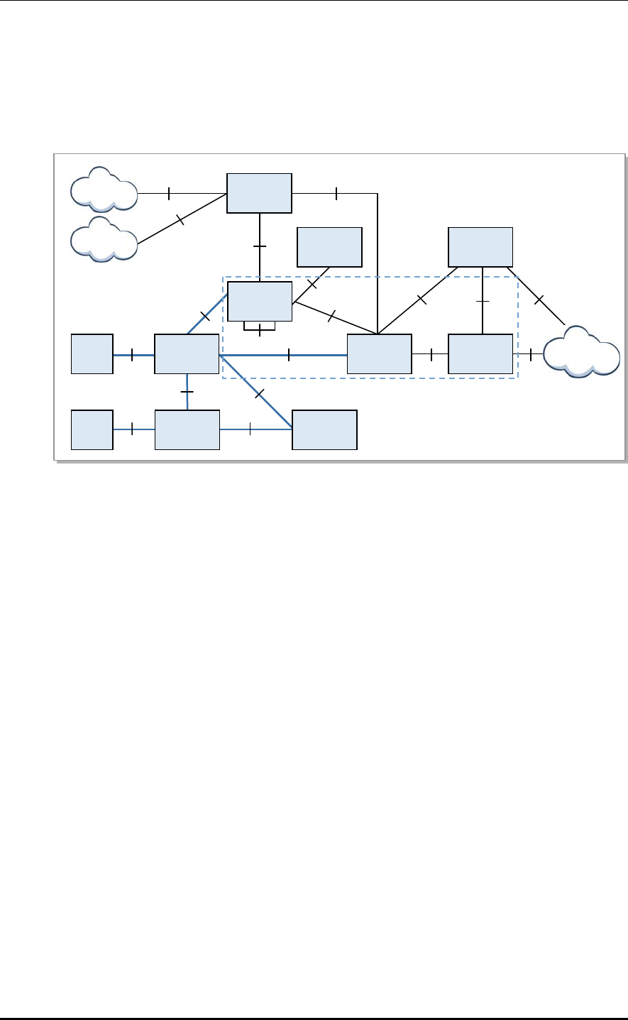
2.4 System-to-System Interface
2.4.1 Interface Architecture
The LTE eNB system provides the following interface to allow interoperation between NEs.
Figure 2.3 LTE eNB System Interface Architecture
Interface between UE and eNB
A physical connection between the UE and eNB is established via radio according to
LTE Air Interface, and the interface standards should satisfy the LTE Uu interface.
The UE interfaces and communicates data with the eNB via radio.
Interface between eNB and EPC
A physical connection between the eNB and EPC is established through the FE (Fast
Ethernet) and GE (Gigabit Ethernet), and the interface standards should satisfy the
interface between the S-GW and LTE S1-U for the user plane, and the interface
between the MME and S1-MME for the control plane.
Interface between eNBs
A physical connection between the eNBs is established through the FE and GE, and
the interface standards should satisfy the LTE X2 interface.
Interface between eNB and LSM
A physical connection between the eNB and LSM is established through the FE and
GE, and the interface standards should satisfy the SNMP/FTP interface.
LTE eNB System Description/Ver.1.0
2.4.2 Protocol Stack
The protocol stack between NEs in the eNB system is as follows:
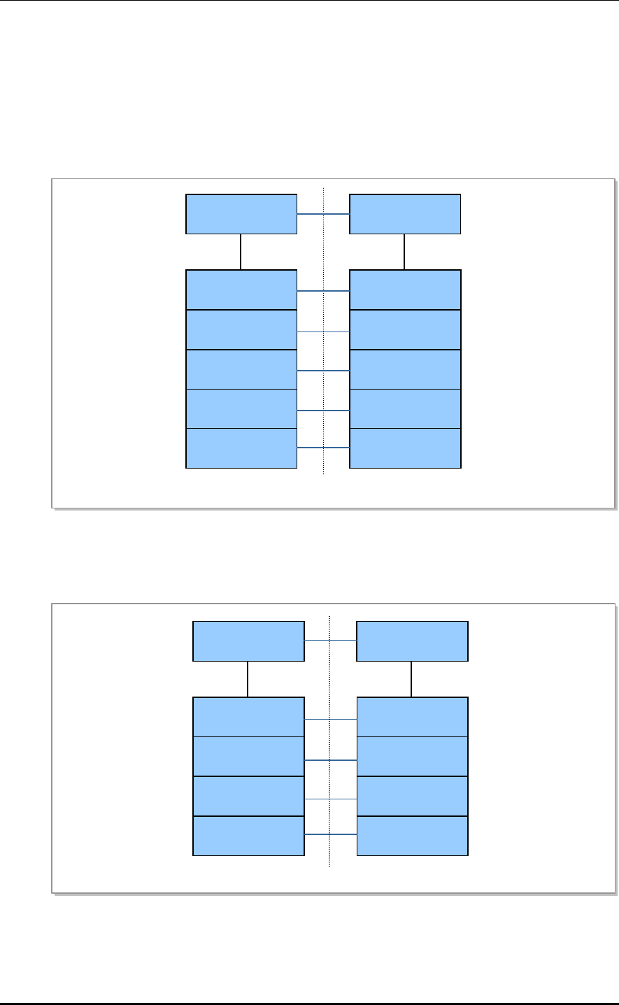
Interface between UE and eNB
The user plane protocol stack consists of PDCP, RLC, MAC, and PHY layers. The user
plane is responsible for transmitting user data (e.g., IP packets) received from the higher
layer. All protocols in the user plane are terminated in the eNB.
The control plane protocol stack consists of NAS, RRC, PDCP, RLC, MAC, and PHY
layers. Located above the wireless protocol, the NAS layer is responsible for UE
authentication between the UE and MME, security control, and paging/mobility
management of UEs in LTE idle mode.
In the control plane, all protocols except the NAS signal are terminated in the eNB.
NAS
RRC
PDCP
RLC
MAC
L1
NAS
S1-AP
SCTP
IP
L2
L1
RRC
PDCP
RLC
MAC
L1
S1-AP
SCTP
IP
L2
L1
UE LTE-Uu eNB
Relay
MME S1-MME
Figure 2.4 UE eNB Protocol Stack
© SAMSUNG Electronics Co., Ltd. 2-19
CHAPTER 2. Overview of LTE eNB
Interface between eNB and EPC
A physical connection between the eNB and EPC is established through the FE and GE,
and the interface standards should satisfy the interface between the LTE S1-U and S1-
MME. The user plane uses the GTP-U (GTP-User) above the IP, and the control plane uses
the SCTP above the IP.
The user plane protocol stacks between the eNB and S-GW are shown below.
eNB
UDP
IP
L2
L1
S-GW
S1-U
UDP
IP
L2
L1
GTP-U GTP-U
User Plane
PDUs
User Plane
PDUs
Figure 2.5 eNB S-GW User Plane Protocol Stacks
The control plane protocol stacks between the eNB and MME are shown below.
eNB
IP
L2
L1
MME
IP
L2
L1
SCTP SCTP
S1-MME
S1-AP S1-AP
Figure 2.6 eNB MME Control Plane Protocol Stacks
2-20 © SAMSUNG Electronics Co., Ltd.
LTE eNB System Description/Ver.1.0
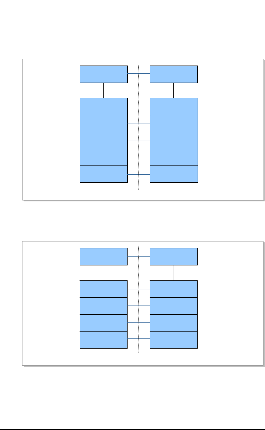
Interface between eNBs
A physical connection between the eNBs is established through the FE and GE, and the
interface standards should satisfy the LTE X2 interface. The user plane protocol stacks
between the eNBs are shown below.
eNB
UDP
IP
L2
L1
eNB
UDP
IP
L2
L1
GTP-U GTP-U
X2
PDUs
User Plane
PDUs
User Plane
Figure 2.7 eNB eNB User Plane Protocol Stacks
The control plane protocol stack is shown below.
eNB
IP
L2
L1
eNB
IP
L2
L1
SCTP SCTP
X2
X2-AP X2-AP
Figure 2.8 eNB eNB Control Plane Protocol Stacks
© SAMSUNG Electronics Co., Ltd. 2-21
CHAPTER 2. Overview of LTE eNB
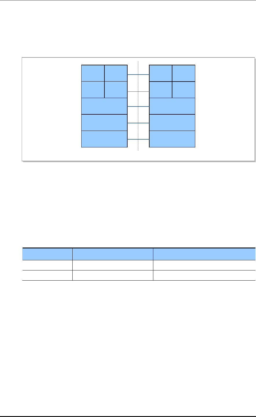
Interface between eNB and LSM
A physical connection between the eNB and LSM is established through the FE and GE,
and the interface standards should satisfy the FTP/SNMP interface. The interface protocol
stacks between the eNB and LSM are shown below.
eNB
IP
L2
L1
LSM
IP
L2
L1
TCP UDP TCP UDP
FTP/SNMP
SNMPFTP
SNMPFTP
Figure 2.9 eNB LSM Interface Protocol Stacks
Physical Interface Options
The LTE eNB provides two types (copper and optic) for the EPC interface, which can be
selected based on network configurations. The interface can be used in any number
according to the LTE eNB capacity and required bandwidth.
The interface types are shown below.
Interface Type Port Type Maximum Number of Ports per System
Copper 1000 Base-T (RJ-45) 2
Optic 1000 Base-LX/SX (SFP) 2
2-22 © SAMSUNG Electronics Co., Ltd.

LTE eNB System Description
CHAPTER 3. LTE eNB Architecture
3.1 Hardware Architecture
The LTE eNB system consists of a digital unit, UADU, and a radio unit, L8HU, of a
common platform. The UADU connects with the L8HU through the CPRI, and is capable
of 2-carrier/3-sector services.
© SAMSUNG Electronics Co., Ltd. 3-1
CHAPTER 3. LTE eNB Architecture
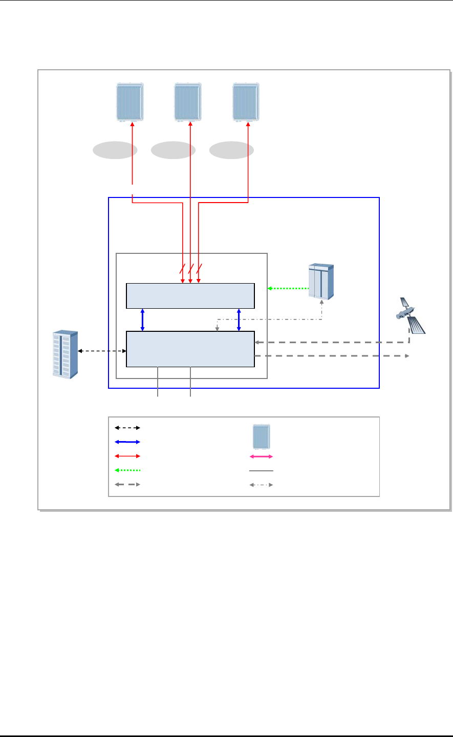
LTE eNB’s Internal Configuration
The following figure shows the internal configuration of the LTE eNB.
UADA
UAMA
L9C
A
(CPRI Optic interface Max.6)
EPC
GPS
TEST
A
nalog 10 MHz/
1PPs
Clock
UDE UDA
GE Traffic +
Alarm/Control +
Clock
333
α secto
r
(3 lines)
β
sec
t
or
(3 lines) γsec
t
or
(3 lines)
Rectifier
/
PDP
Ethernet
-48 VDC
Backhaul interface (FE/GE)
FE/GE
LTE Outdoor Rack
Traffic + Alarm/Control + Clock
CPRI Optic
-48 VDC
Clock
Rectifier Ethernet Interface
External Interface (UDA, UDE)
Analog IF
8HU (LTE 700 MHz, 2Tx4Rx) L
Figure 3.1 Removable eNB’s Internal Configuration
2Tx/4Rx is supported by default in the UADU, and up to three L9CAs (LTE eNB Channel
card board Assembly) can be mounted additionally. A maximum of 5 MHz 2-carrier/3-sector
can be supported.
The L9CA has a capacity of 5MHz 2-carrier/3-sector (2Tx/2Rx) per board, by default.
The four slots of the UADU are multi-board type slots where the UAMA carries out the
main processor function, network interface function, clock generation and distribution
function, provider-requested alarm processing, etc. and the L9CA carries out the modem
function. The power module, FAN, and dust filter are also installed.
3-2 © SAMSUNG Electronics Co., Ltd.
LTE eNB System Description/Ver.1.0
The L8HU is an RF integration module consisting of a transceiver, power amplifier, and
filter. It sends and receives traffic, clock information, and alarm/control messages to and
from the L9CA. It has a 2Tx/4Rx structure with optic CPRI support.
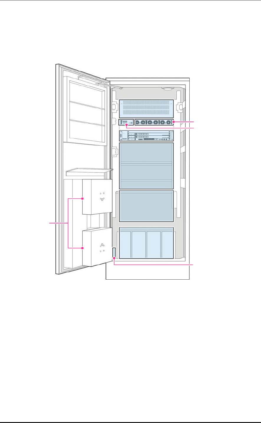
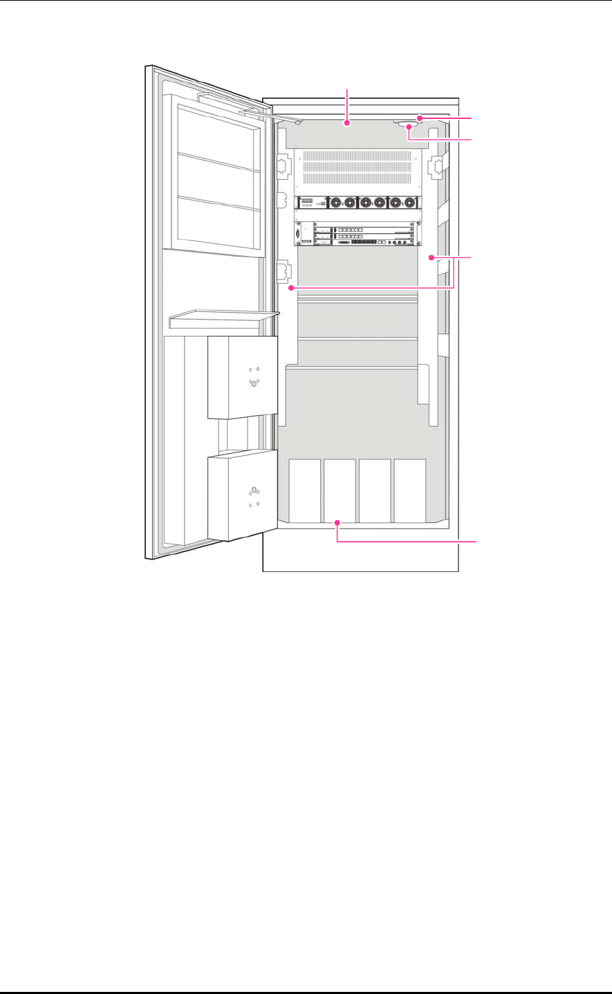
The following shows the configuration of LTE’s outdoor eNB.
DC Distribution
UADU
User Space
Reserved Battery
Space
Battery
Fan
Rectifier
Smartpack
I/O Monitor
Figure 3.2 Outdoor eNB Configuration
© SAMSUNG Electronics Co., Ltd. 3-3
CHAPTER 3. LTE eNB Architecture
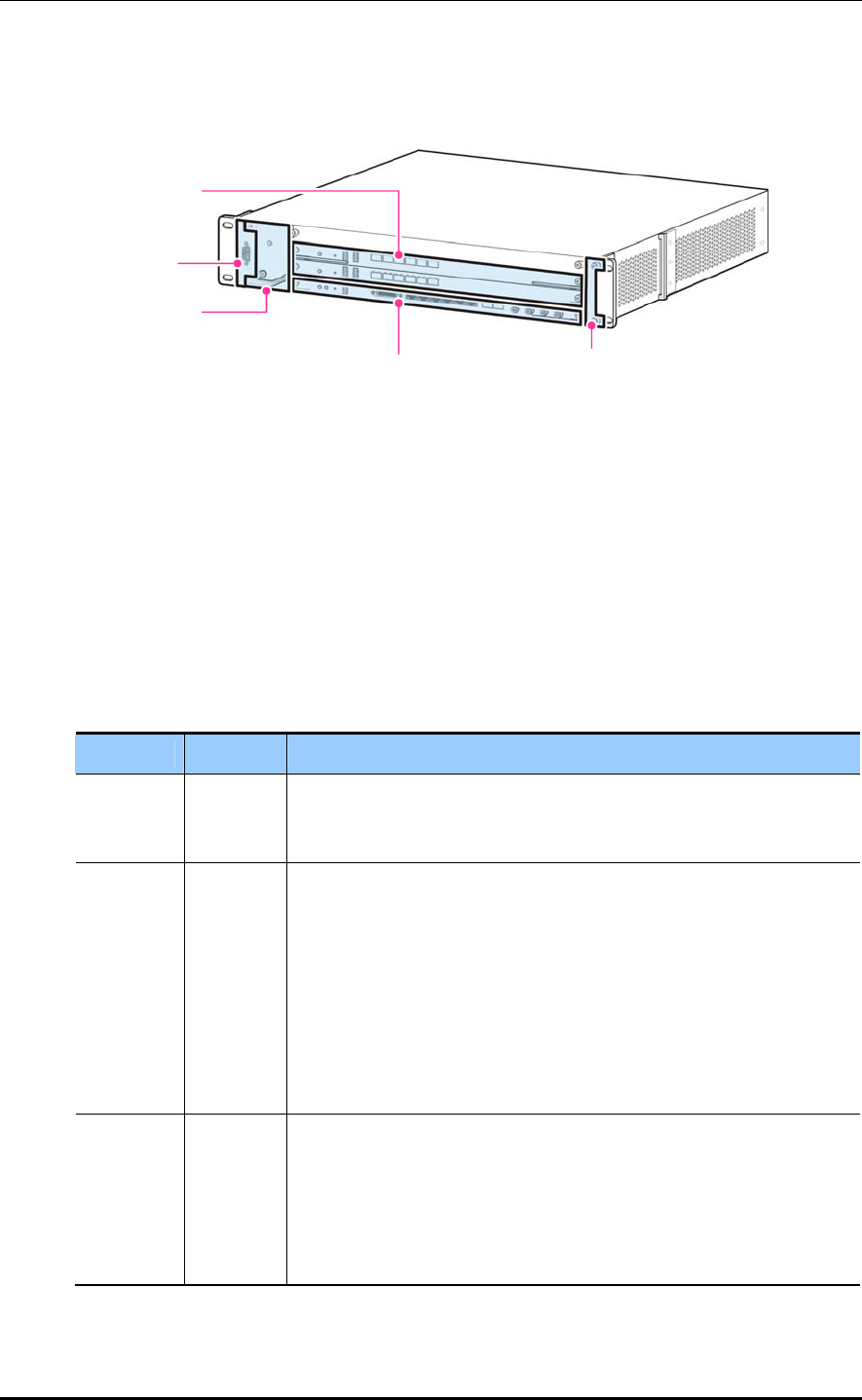
3.1.1 UADU
The following shows the configuration of the UADU.
Power
Dust Filter
UAMA
FANM-C4
L9CA
Figure 3.3 Configuration
The UADU is the Multi-board type in which the UAMA that carries out the main processor
function, network interface function, and clock creation and distribution function and the
L9CA that carries out the modem function are mounted. It consists of the power module,
FANM-C4 module, and dust filter.
The UADU is mounted on a 19 inch rack, with fan cooling and EMI available in each unit,
and has a capacity of up to 2-carrier/3-sector per a single L9CA. In addition to optic CPRI
with the L8HU, up to six optic ports per channel card are available.
The following table shows the key features and configurations of each board.
Board Quantity Description
UADB 1 Universal platform type A Digital Backplane board assembly
- UADU’s backboard
- Routing signals for traffic, control, clocks, power, etc.
UAMA 1 Universal platform type A Management board Assembly
- Main processor in the system
- Resource allocation/operation and maintenance
- Alarm collection and report to LSM
- Backhaul support (GE/FE)
- UADU FAN alarm handling
- Provides the interface for rectifier alarms
- Provides UDE (User Defined Ethernet) and UDA (User Defined Alarm)
- Generates and supplies GPS clocks (sync in & out)
L9CA Max. 3 LTE eNB Channel card board Assembly
- Call processing, resource allocation/operation and maintenance
- OFDMA/SC-FDMA Channel Processing
- Interface between the L8HU and optic CPRI
- Support for optic interface with CPRI RRH (E/O, O/E conversion in
CPRI Mux)
3-4 © SAMSUNG Electronics Co., Ltd.

LTE eNB System Description/Ver.1.0
UAMA
The UAMA acts as a main processor of the UADU, and is responsible for network and
external interfacing, reset, and clock generation/distribution.
Main Processor
The eNB’s main processor is a board acting in the topmost role of the eNB, and is
responsible for communication path setups between the UE and EPC, Ethernet
switching in the eNB, and system operation/maintenance. It also manages the status
for all hardware/software in the eNB, allocates and manages resources, collects alarms,
and reports all status information to the LSM.
Network Interface
The UAMA directly interfaces with the EPC through the GE/FE and supports a total of
four ports (two optic and two copper ports). If only one type of port (either optic or
copper) is used, ports not in use can be other UDEs.
External Interface
The UAMA provides the Ethernet interface for UDE in the UADU, and paths for
alarm information generated in external devices (additional devices supplied by the
provider) as well as reporting alarm information to the LSM.
Reset
The UAMA provides the reset function for each board.
Clock Generation and Distribution
By using the PP2S (even clock), digital 10 MHz signals received from the UCCM
(Universal Core Clock Module), the UAMA generates 10 MHz, even, and System
Fame Number (SFN) clocks for synchronization and distributes them to the hardware
blocks.
These clocks are used to maintain internal synchronization in the eNB and to operate
the system.
The UAMA also provides analog 10 MHz and 1 pps for measuring and relaying
equipments.
The UCCM transmits time information and location information through the TOD
(Time Of Day) path.
If the UCCM fails to receive GPS (Global Positioning System) signals due to an error
during system operation, it carries out the holdover function that supplies the normal
clocks that have been provided for a specific period of time.
L9CA
The L9CA is responsible for subscriber channel handling and CPRI interfacing.
Subscriber Channel Processing Function
The L9CA modulates the packet data received from the upper processor and transmits
it to the RF part via CPRI. In the other direction, it demodulates the packet data
received from the RF, converts them to the format which is defined in the LTE
standard physical layer specifications, and transmits them to the upper processor.
CPRI Interface
The L9CA interfaces via the L8HU and CPRI.
© SAMSUNG Electronics Co., Ltd. 3-5

CHAPTER 3. LTE eNB Architecture
3.1.2 L8HU
The following shows the configuration of L8HU.
[Top View]
[Front View] [Bottom View]
Figure 3.4 L8HU Configuration
By default, the L8HU is installed outdoors for natural cooling.
The L8HU consists of a 2Tx/4Rx RF chain as an integrated RF unit with a transceiver,
power amplifier and filter installed in the single outdoor unit. It can support 10 MHz and
15 MHz bandwidth with firmware changes.
In the downlink path, the L8HU performs O/E conversion for the baseband signals received
from the UADU via the optic CPRI. The converted O/E signals are converted again into
analog signals by the DAC. The frequency of those analog signals is up converted through
the modulator and then those signals are amplified into high-power RF signals through the
power amplifier. The amplified signals are sent to the antenna through the filter part.
In the uplink path of the L8HU, the RF signals received through the filter part are amplified
low noise in the LNA (Low Noise Amplifier) and their frequency is then down-converted
through the demodulator. These down-converted frequency signals are converted to
baseband signals through the ADC. The signals converted into baseband are changed to
E/O through the CPRI and sent to the UADU. The control signals of the L8HU are
transmitted through the control path in the CPRI.
3-6 © SAMSUNG Electronics Co., Ltd.

LTE eNB System Description/Ver.1.0
The main functions are as follows
Unit Description Configuration
L8HU LTE eNB remote radio Head Unit
- 700 MHz (DL 728~746 MHz, UL 698~716 MHz)
- Support for 5 MHz 2Tx4Rx per L8HU
- Support for 5 MHz 2-carrier/1-sector
- 20 + 20 W per carrier (40 W total)
- Up/Down RF conversion
- Low-noise amplifier
- RF high-power amplification
- Spurious wave suppression outside the bandwidth
- Includes E/O and O/E conversion modules for optic communications
with UADU.
- Support for RET (Remote Electrical Tilt)
Distributed type
© SAMSUNG Electronics Co., Ltd. 3-7
CHAPTER 3. LTE eNB Architecture
3.1.3 Power supply
The following shows the configuration of the outdoor eNB’s power supply.
Smartpack
Rectifier
DC Distribution
Figure 3.5 Power Supply
Unit Quantity Description
DC Distribution 1 Divides the DC power from the rectifier to provide a supply to the
UADU, L8HU and additional devices.
Smartpack 1 Controls the rectifier and reports to the UAMA with alarms collected
by the I/O monitor.
Rectifier 3 Supplies DC power to the system. Up to three rectifiers can be
mounted.
3-8 © SAMSUNG Electronics Co., Ltd.
LTE eNB System Description/Ver.1.0
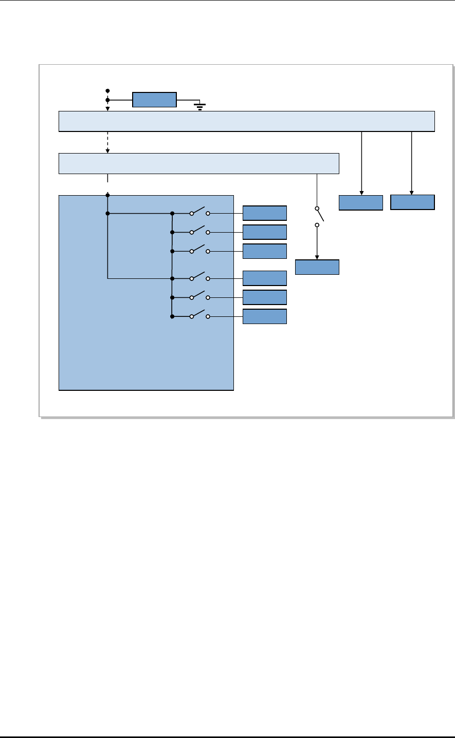
The type of power supplied to the outdoor eNB and the connection points are shown in the
power diagram below.
SPD: Surge Protect Device
BATTERY
L8HU 2
L8HU 1
L8HU 0
DC5
DC4
AC 220 V
AC SPD
AC BOX
INPUT
OUTPUT AC 220 V
OUTLET/HEATER
Rectifier
DC Distribution
DC0
DC1
DC2
DC -48 V BATT
TERMINAL
HEATER
OUTLET
UADU
CSR
SPARE
DC3
Figure 3.6 Power Diagram
The input power (220 VAC) is directly supplied to the outlet and heater through the AC box,
and converted through the rectifier into DC -48 V. DC -48 V goes to the DC distribution,
and is distributed through the circuit breaker to the CSR, UADU, L8HU, etc.
© SAMSUNG Electronics Co., Ltd. 3-9
CHAPTER 3. LTE eNB Architecture
3-10 © SAMSUNG Electronics Co., Ltd.
Smartpack
I/O monitor
FANM-C4
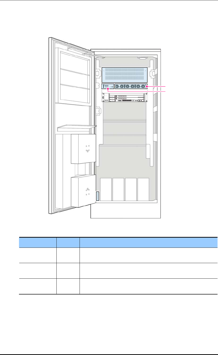
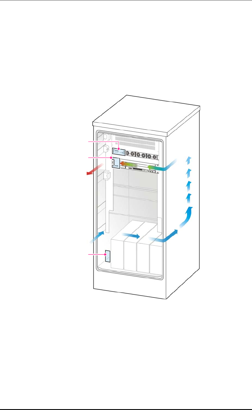
3.1.4 Environmental Devices
Mounted on the front door of the outdoor rack, FAN adjusts the system temperature by
discharging heated air in the rack outside.
If the system’s internal temperature is above the optimum, the smartpack and I/O monitor
control the FAN to decrease the temperature. If the system’s internal temperature reaches
the optimum, the smartpack and I/O monitor adjusts the FAN speed to control the
temperature.
Figure 3.7 Outdoor eNB’s Heat Discharge
LTE eNB System Description/Ver.1.0
The following table shows the outdoor eNB’s environmental devices.
Name Quantity Function
FAN 2 - Outdoor rack’s cooling fan
- Controls the fan according to the system’s internal temperature
detected through the sensor installed in the rack
Room temperature mode: Low-speed operation
High temperature mode: High-speed operation.
FANM-C4 1 Fan Module-C4
UADU’s cooling fan
SmartPack &
I/O monitor
1 - The built-in sensor detects the system temperature.
- Collects fire alarms
- Collects ‘door open’ alarms
- Collects flood alarms
- Collects ‘door fan’ alarms
- Reports collects alarms to the UAMA
Sensor 5 Sensors for temperature (2), flood (1), fire (1) and door (1)
UADU
A cooling fan is installed to keep the UADU shelf’s internal temperature optimal.
This allows the UADU to operate normally regardless of changes to the external temperature.
The UADU’s heat-discharge mechanism is shown below.
FANM-C4 Dust Filter
Figure 3.8 UADU Heat-Discharge Mechanism
L8HU
The L8HU is designed to discharge heat effectively through natural cooling without an
additional cooling device.
© SAMSUNG Electronics Co., Ltd. 3-11
CHAPTER 3. LTE eNB Architecture
The following shows the outdoor eNB’s sensors.
Lamp
Fire sensor
Door sensor
Flood sensor
Temp sensor
Figure 3.9 Sensors
The smartpack and I/O monitor maintain/control the outdoor rack’s internal temperature,
and collect/report external environment alarms.
The smartpack and I/O monitor detects the rack’s internal temperature through the sensor
in the air outlet of the UADU to control the FAN speed. They are connected to the
environmental sensors (for temperature, flood, fire and door) installed in the rack to gather
environment data real-time, and report environment alarms to the LSM at the UAMA.
3-12 © SAMSUNG Electronics Co., Ltd.
LTE eNB System Description/Ver.1.0
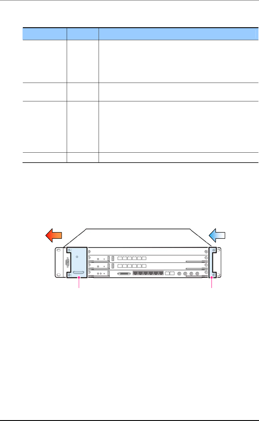
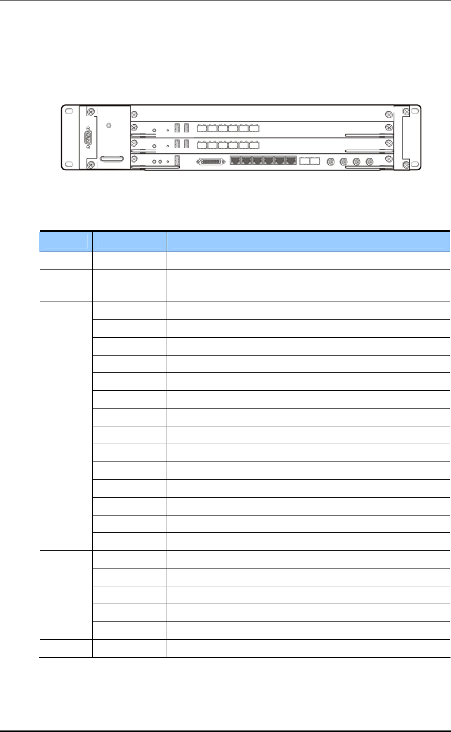
3.1.5 External Interface
External Interfaces of UADU
The following shows the interfaces of UADU.
A
CT RST DBG0 DBG1
L0
L1 L2
L3 L4
L5
-48 V
A
/F
A
CT RST DBG0 DBG1
L0
L1 L2
L3 L4 L5
PWR/ALM
PWR
RTN
UDA BH0 BH1 UDE0 UDE1 EDBG REC BH2
BH3
FANM-C4
A
CT GPS RST DBG
1PPS A10M GPS0 GPS1
Figure 3.10 UADU External Interface
Unit Interface Description
PWR RTN/-48 V Power Input (RTN/-48 V)
FANM-C4 PWR/ALM Fan Module-C4
UADU’s cooling fan
ACT CPU Active LED
GPS UCCM Status LED
RST Reset Switch (CPU Chip Reset)
DBG For the debugger (UART, RS-232)
UDA User Defined Alarm (Rx: 9 port, Tx: 2 port), Mini Champ
BH0, BH1 Copper Backhaul (1000Base-T), RJ-45
UDE0, UDE1 User Defined Ethernet (1000Base-T), RJ-45
EDBG For the debugger (10/100/1000Base-T), RJ-45
REC For the rectifier, RS-485
BH2, BH3 1000Base-LX or SX, RJ-45
1PPS Test Port 1PPS Output (from UCCM), SMA
A10M Test Port Analog 10 M Output (from UCCM), SMA
GPS 0 GPS ANT Input #0 (to UCCM), SMA
UAMA
GPS 1 GPS ANT Input #1 (to UCCM), SMA
ACT L9CA ACT LED
RST System reset
DBG0, DBG1 UART DSP Debug, USB
L0~5 L8HU IF (CPRI 4.0), Optic
L9CA
EDBG 10/100/1000 Base-T, RJ-45
Dust filter A/F Dust filter
© SAMSUNG Electronics Co., Ltd. 3-13
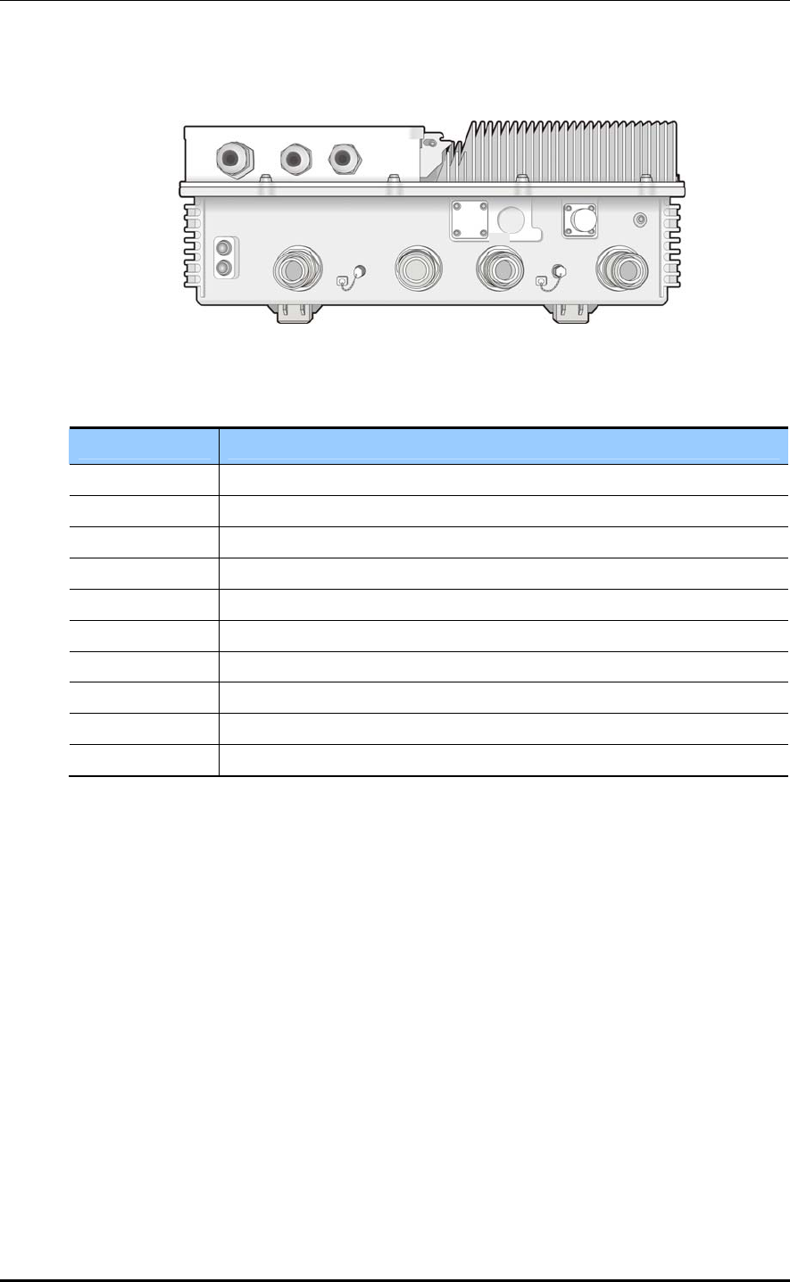
CHAPTER 3. LTE eNB Architecture
L8HU External Interface
The following shows the external interfaces of L8HU.
TXMON0 TXMON1
Ground
TRX1 RX3TRX0
PWR
OPT 0/1
RET
RX2
[Bottom View]
Figure 3.11 L8HU External Interface
Interface Description
PWR DC -48 V power input port
Ground Frame Ground
OPT 0/1 Optic cable terminal connected to the UADU (cable gland)
RX2 RF receiving terminal #2
TXMON0 Tx signal monitoring terminal #0
TRX0 RF Tx/Rx terminal #0
RX3 RF receiving terminal #3
TXMON1 Tx signal monitoring terminal #1
TRX1 RF Tx/Rx terminal #1
RET AISG connector for remote electric tilting
3-14 © SAMSUNG Electronics Co., Ltd.
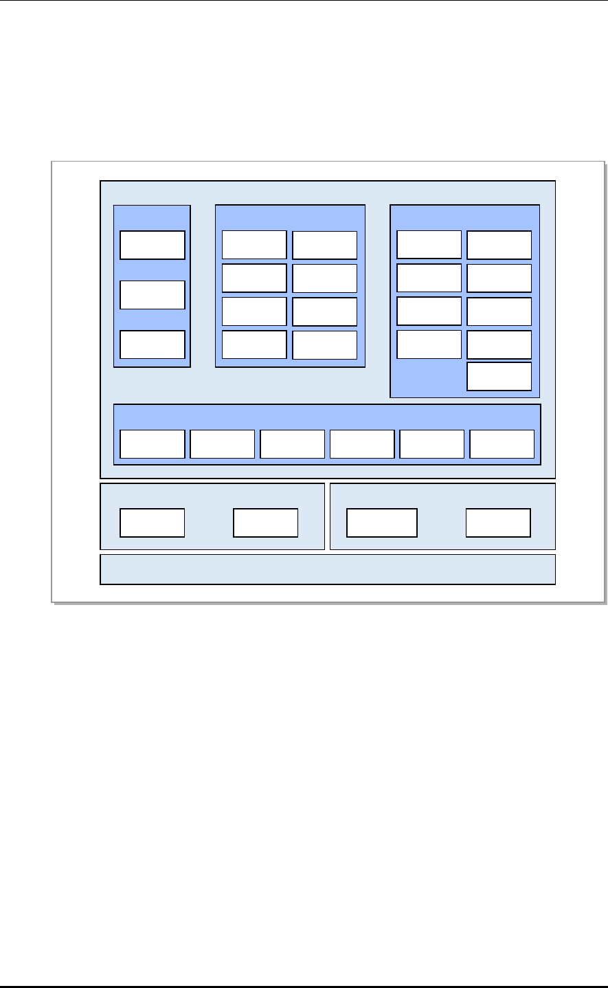
LTE eNB System Description/Ver.1.0
3.2 Software Architecture
3.2.1 Basic Software Architecture
The LTE eNB software is divided into three parts, kernel space (OS/DD), forwarding space
(NPC and NP), and user space (MW, IPRS, CPS and OAM). Below is described each part.
Hardware
Forwarding Space
NPC NP
IPRS
IPRS
IPSS
DHCP
CPS
ECMB
ECCB
SCTB
CSAB
GTPB
PDCB
RLCB
MACB
TM/TrM
SwM
SNMP
OSAB
CLI
Web-EMT
ENS MFS DUS
MW
MDS THS HAS
Kernel Space
OS DD
DHCP
CM
FM
PM
OAM
User Space
Figure 3.12 eNB Software Architecture
Operating System (OS)
The OS resets/controls hardware devices and allows the software on those devices to run.
It consists of the booter, kernel, root file system (RFS) and utility.
Booter: A module that performs initialization on boards. It initializes the CPU, L1/L2
Cache, UART, and MAC and the devices such as CPLD and RAM within each board,
and runs the u-boot.
Kernel: Manages the operation of multiple software processes and provides various
primitives to optimize the use of limited resources.
RFS: Stores and manages the binary files, libraries, and configuration files necessary
for running and operating the software in accordance with the File-system Hierarchy
Standard (FHS) 2.2.
Utility: Provides the functions for managing the CPLD (Complex Programmable
Logic Device), LED, watchdog, and environment and inventory information,
measuring and viewing the CPU load, and storing and managing fault information
when a processor goes down.
© SAMSUNG Electronics Co., Ltd. 3-15

CHAPTER 3. LTE eNB Architecture
Device Driver (DD)
The device driver allows applications to operate normally on devices that are not directly
controlled from the OS in the system. It consists of a physical DD and virtual DD.
Physical DD: Provides the interface through which an upper application can configure,
control, and monitor the external devices of the processor. (Switch DD and Ethernet
MAC driver, etc.)
Virtual DD: Virtualizes the physical network interfaces in the kernel so that high-level
applications control the virtual interfaces, rather than the physical network interfaces
directly.
NPC (Network Processing Control)
The NPC creates/manages tables to process NP software packets and gathers/manages
network statistics and statuses by interfacing with high-level processes such as IPRS and
OAM.
Network Processing (NP)
The NP software processes packets necessary for backhaul interfacing.
The NP has the following features.
Packet RX and TX
IPv4 and IPv6
Packet queuing and scheduling
MAC filtering
IP Packet forwarding
IP fragmentation and reassembly
Link aggregation
VLAN termination
ACL (Access Control List)
Middleware (MW)
The MW ensures seamless communication between OS and applications on various
hardware environments. It provides a message delivery service (MDS) between
applications, debugging utility service (DUS), event notification service (ENS), high
availability service (HAS) for redundancy management and data backup, task handling
service (THS).
MDS: Provides all services related to message sending and receiving.
DUS: Provides the function for transmitting debugging information and command
between the applications and the operator.
ENS: Registers and manages various events such as timers, and provides the function
for sending an event message to the destination at the time when it is needed.
HAS: Provides the data synchronization function and the redundancy state
management function.
3-16 © SAMSUNG Electronics Co., Ltd.

LTE eNB System Description/Ver.1.0
THS: Provides the task creation/termination function, the task control function, and
the function for providing task information, etc.
Miscellaneous Function Service (MFS): The MFL is responsible for all hardware-
dependent functions, such as accessing physical addresses of hardware devices.
IP Routing Software (IPRS)
The IP routing software is responsible for IP routing and security for the eNB backhaul.
The IPRS consists of IPRS, IPSS (IP Security Software), DHCP (Dynamic Host
Configuration Protocol), each with the following features:
IPRS: Collects and manages the system configuration and status information necessary
for IP routing. Based on this data, the IPRS provides the function for creating routing
information.
Ethernet, VLAN-TE, link aggregation management
Ethernet OAM
IP address management
IP routing information management
QoS management
IPSS: Software to perform the security function for the IP layer. It performs the
filtering function referring to IP address, TCP/UDP port number, and protocol type.
DHCP: Software block to perform the automatic IP address allocation function.
The DHCP provides the function for obtaining an IP address automatically by
communicating with the DHCP server.
© SAMSUNG Electronics Co., Ltd. 3-17
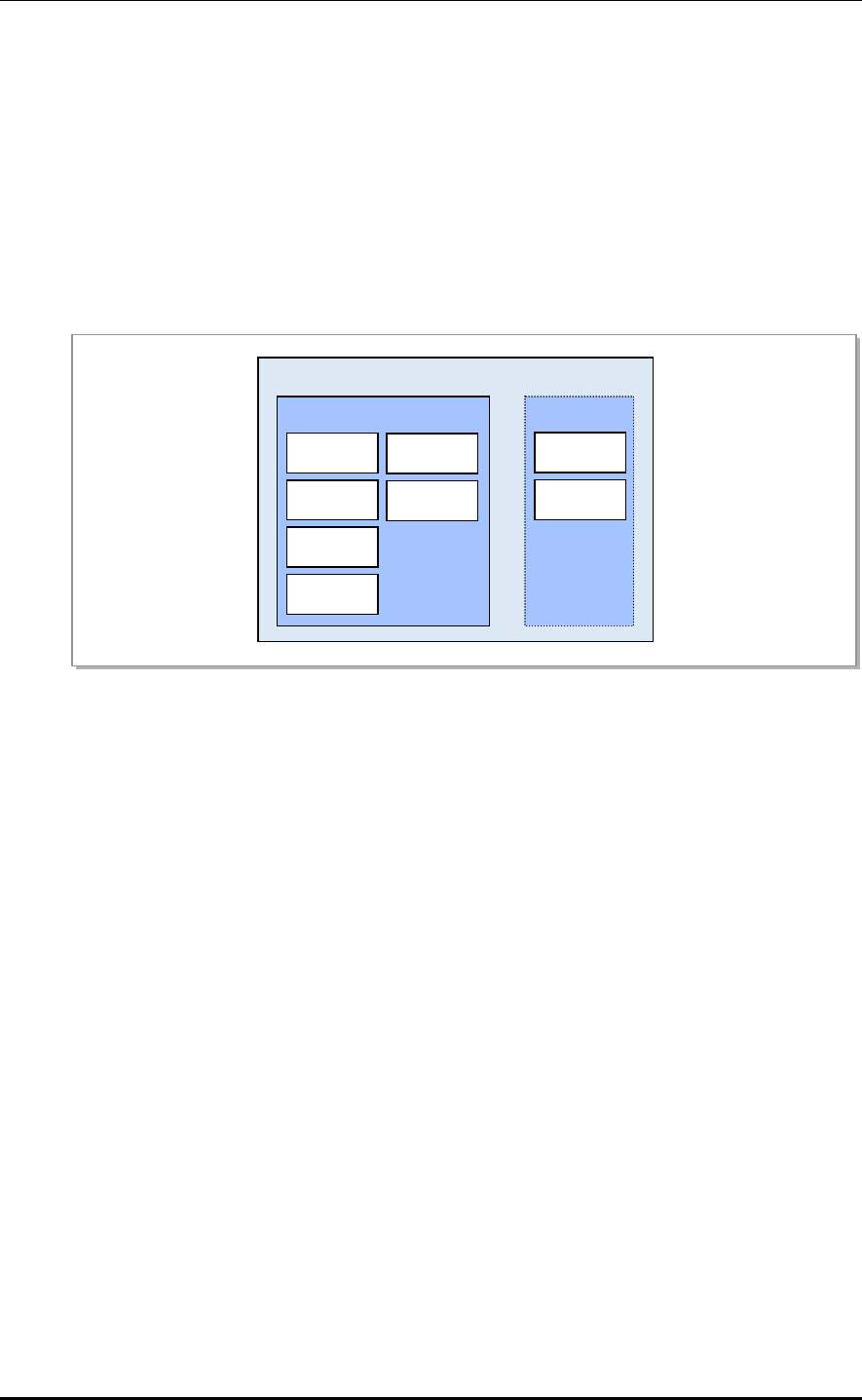
CHAPTER 3. LTE eNB Architecture
3.2.2 CPS Block
The CPS (Call Processing Software) block performs the resource management of the LTE
eNB and the call processing function in the eNB defined in the 3GPP and performs the
interface function with the EPC, UE, and adjacent eNBs. The CPS consists of the eNB
control processing subsystem (ECS) for network access and call control, and the eNB data
processing subsystem (EDS) for user traffic handling.
According to eNB specifications by the 3GPP, the ECS is composed of the SCTB, ECMB,
ECCB, SCTB and CSAB. The EDS is composed of GTPB, PDCB, RLCB and MACB.
The following shows the CPS architecture.
UAMA
GPRS
Packet
L9CA
Radio
Medium
CSAB
eNB Call
eNB
Stream
CPS
Figure 3.13 CPS Architecture
Stream Control Transmission protocol Block (SCTB)
The SCTB acts as the S1 interface between the eNB and the MME, and as the X2 interface
with the adjacent eNBs. It runs on the UAMA.
The SCTB has the following major functions:
S1 interfacing
X2 interfacing
eNB Common Management Block (ECMB)
The ECMB is responsible for call processing per eNB/cell, such as transmitting system
information and controlling the eNB overload. It runs on the UAMA.
The ECMB has the following major functions:
Cell setting/release
System information transmission
eNB overload control
Access barring control
Resource measurement control
Cell load information transmission
3-18 © SAMSUNG Electronics Co., Ltd.

LTE eNB System Description/Ver.1.0
eNB Call Control Block (ECCB)
The ECCB is responsible for controlling a series of call processes between call setting and
release as well as for processing calls from the MME and neighbor eNB. It runs on the
UAMA.
The ECCB has the following major functions:
Radio Resource Management
Idle-Active status transition
Bearer setting/change/release
Paging
MME selection and load balancing
Call admission control
Security
Handover control
UE measurement control
Statistics processing
SON-related call processing (mobility robustness and RACH optimization)
CPS SON Agent Block (CSAB)
The CSAB acts as a self-organizing network (SON) performed by the eNB CPS, and runs
on the UAMA.
The CSAB has the following major functions:
Mobility robustness optimization
RACH optimization
GPRS Tunneling Protocol Block (GTPB)
The GTPB is responsible for GTP handling as part of call processing in the eNB user plane,
and runs on the UAMA.
The GTPB has the following major functions:
GTP tunnel control
GTP management
GTP data transmission
© SAMSUNG Electronics Co., Ltd. 3-19

CHAPTER 3. LTE eNB Architecture
PDCP Block (PDCB)
The PDCB is responsible for PDCP handling as part of call processing in the eNB user
plane, and runs on the UAMA.
The PDCB has the following major functions:
Header compression/decompression: ROHC only
User and control plane data transmission
PDCP sequence number maintenance
DL/UL data forwarding during handover
User and control data ciphering/deciphering
Control data integrity protection
Timer based PDCP SDU discard
Radio Link Control Block (RLCB)
The RLCB is responsible for RLC protocol handling as part of call processing in the eNB
user plane, and runs on the L9CA.
The RLCB has the following major functions:
Higher-layer PDU transmission
Automatic repeat request (ARQ) for AM mode data transmission
RLC SDU concatenation, segmentation and reassembly
Re-segmentation of RLC data PDUs
In sequence delivery
Duplicate detection
RLC SDU discard
RLC re-establishment
Protocol error detection and recovery
Medium Access Control Block (MACB)
The MACB is responsible for MAC protocol handling as part of call processing in the eNB
user plane, and runs on the L9CA.
The MACB has the following major functions:
Mapping between logical and transport channels
Multiplexing & de-multiplexing
HARQ
Transport format selection
Priority handling between UEs
Priority handling between logical channels of one UE
3-20 © SAMSUNG Electronics Co., Ltd.

LTE eNB System Description/Ver.1.0
3.2.3 OAM Blocks
The operation and maintenance (OAM) block is responsible for eNB operations and
maintenance.
The OAM consists of the OSAB, PM, FM, CM, SNMP, SwM, TM, TrM, Web-EMT and CLI.
The OAM has the following major functions:
OSAB (OAM SON Agent Block)
Self-configuration and self-establishment of system information
Automatic neighbor relation (ANR) optimization
Energy saving management
Performance management (PM)
Statistics collection
Statistics storage
Statistics transmission
Fault management (FM)
Fault detection and alarm reporting
Alarm view
Alarm filtering
Alarm severity setting
Alarm threshold setting
Alarm correlation
Status management and reporting
Status view
Configuration management (CM)
System/cell addition/removal
Configuration view/change/add/remove
Call parameter view/change
Neighbor view/change/add/remove
SNMP (Simple Network Management Protocol)
Interface with the SNMP Manager
© SAMSUNG Electronics Co., Ltd. 3-21

CHAPTER 3. LTE eNB Architecture
3-22 © SAMSUNG Electronics Co., Ltd.
SwM (Software Management)
Software and data file download/install
Hardware unit and system reset
Status monitoring of software units in operation
Software and firmware information management/update
Software upgrade
Inventory management
Test management (TM)
OCNS (Orthogonal Channel Noise Simulator) setting/release
Model setting/release
Ping test
Tx/Rx output measurement
Antenna VSWR (Voltage Standing Wave Ratio) measurement
Trace management (TrM)
Call trace
Web-EMT (Web-based Element Maintenance Terminal)
Web server
Operation with other OAM blocks for processing commands
Command Line Interface (CLI)
CLI user management
Command input and output display
Fault/status message display

LTE eNB System Description
CHAPTER 4. Message Flows
4.1 Call-Processing Message Flows
This chapter describes message flow diagrams and functions for attach, service request,
detach and handover processes. The handover process includes the intra E-UTRAN
handover and inter-RAT (UTRAN) handover processes. The message flow diagram and
function of the CS fallback process as part of the inter RAT (UTRAN, GERAN) operation
are described below.
© SAMSUNG Electronics Co., Ltd. 4-1
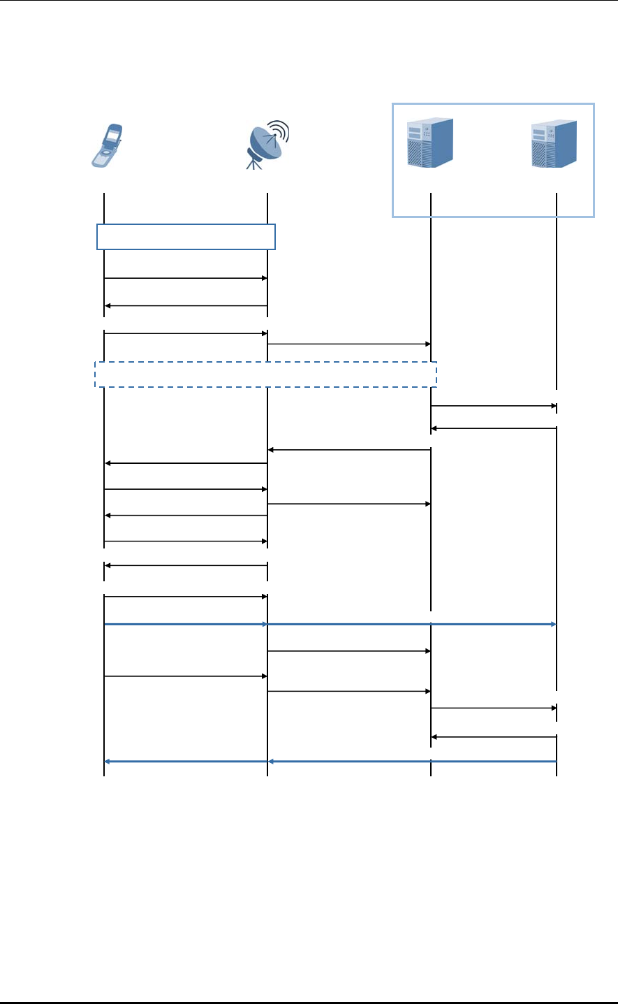
CHAPTER 4. Message Flows
Attach Process
The figure below shows the message flow of the Attach procedure.
UE eNB MME S-GW
EPC
Downlink data
Downlink data
1) Random Access Procedure
2) RRCConnectionRequest
3) RRCConnectionSetup
4) RRCConnectionSetupComplete
(Attach Request) 5) Initial UE Message
(Attach Request)
6) Authentication/NAS Security Setup
10) UECapabilityEnquiry
11) UECapabilityInformation
13) SecurityModeCommand
14) SecurityModeComplete
15) RRCConnectionReconfiguration
(Attach Accept)
18) ULInformationTransfer
(Attach Complete)
(Attach Complete)
19) Uplink NAS Transport
17) Initial Context Setup
Response
(Attach Accept)
9) Initial Context Setup Request
7) Create Session Request
8) Create Session Response
20) Modify Bearer Request
21) Modify Bearer Response
Uplink data Uplink data
12) UE Capability Info Indication
16) RRCConnectionReconfiguration Complete
Figure 4.1 Attach Process
4-2 © SAMSUNG Electronics Co., Ltd.

LTE eNB System Description/Ver.1.0
Step Description
1 The UE runs the Random Access process (TS 36.321, 5.1) with the eNB.
2-4 The UE initializes the RRC Connection Establishment process (TS 36.331, 5.3.3).
The UE includes the ATTACH REQUEST message (NAS) in the
RRCConnectionSetupComplete message (PRC) and sends it to the eNB.
5 The eNB induces the MME from the RRC factors, includes the ATTCH REQUEST
message in the INITIAL UE message, which is an S1-MME Control message, and
sends it to the MME.
6 If there is no UE context in the network, the integrity of the ATTACH REQUEST
message is not protected, or the integrity check fails, then authentication and NAS
security setup are performed as a requisite. The UE runs the Evolved Packet System
(EPS) Authentication and Key Agreement (AKA) process (TS 33.401, 6.1.1) with the
MME. The MME establishes an NAS security association with the UE using the NAS
Security Mode Command (SMC) process (TS 33.401, 7.2.4.4).
7-8 The MME selects the P-GW and S-GW. The MME sends the Create Session Request
message to the S-GW. The S-GW adds an item to the EPS bearer table.
From this step and until it receives the Modify Bearer Request message of Step 20, the
S-GW stores the downlink packet received from the P-GW. The S-GW sends the Create
Session Response message back to the MME.
9 The MME includes the ATTACH REQUEST message in the INITIAL CONTEXT SETUP
REQUEST message, which is an S1-MME Control message, and sends it to the eNB.
This S1 message also includes the AS security context information on the UE, which
starts the RRC-level AS SMC process.
10-12 If the INITIAL CONTEXT SETUP REQUEST message doesn’t have UE Radio
Capability IE, the eNB starts the process to obtain UE Radio Capability from the UE,
and sends the results to the MME.
13-14 The eNB sends the Security Mode Command message to the UE, and the UE responds
with the SecurityModeComplete message. In the eNB, downlink encryption must start
after Security Mode Command is transmitted and the uplink decryption must start after
Security Mode Complete is received.
In the UE, the uplink encryption must be started after the SecurityModeComplete
message has been sent, and the downlink decryption must be started after the
SecurityModeCommand message has been received (TS 33.401, 7.2.4.5).
15-16 The eNB includes ATTACH ACCEPT in the RRC Connection Reconfiguration message
and sends it to the UE. The UE sends the RRC Connection Reconfiguration Complete
message to the eNB.
After receiving the ATTACH ACCEPT message, the UE can send uplink packets to the
S-GW and P-GW via the eNB.
17 The eNB sends the INITIAL CONTEXT SETUP RESPONSE message to the MME.
18-19 The UE sends the UL Information Transfer message containing the ATTACH
COMPLETE to the eNB. The eNB passes the UPLINK NAS TRANSPORT message
containing the ATTCH COMPLETE to the MME.
20-21 After receiving both of the INITIAL CONTEXT RESPONSE message at step 17 and the
ATTACH COMPLETE message at step 19, the MME sends the Modify Bearer Request
message to the S-GW.
The S-GW sends the Modify Bearer Response message to the MME, and then can
send the stored downlink packets.
© SAMSUNG Electronics Co., Ltd. 4-3
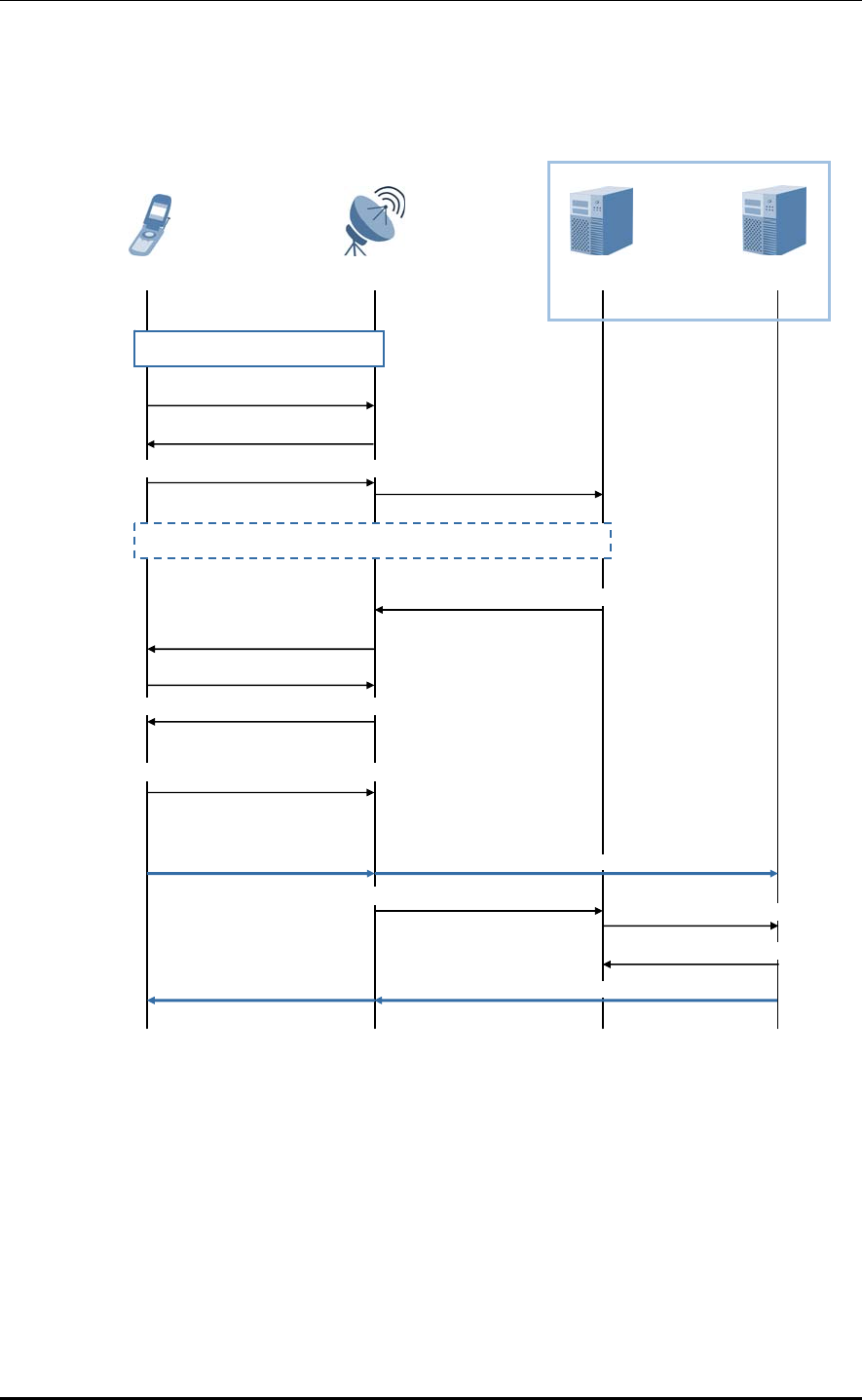
CHAPTER 4. Message Flows
Service Request Initiated by the UE
The figure below shows the message flow of the Service Request procedure initiated by the
UE.
UE eNB MME S-GW
EPC
Downlink data
Downlink data
14) Modify Bearer Response
13) Modify Bearer Request
1) Random Access Procedure
2) RRCConnectionRequest
3) RRCConnectionSetup
4) RRCConnectionSetupComplete
(Service Request) 5) Initial Message
(Service Request)
6) Authentication/NAS Security Setup
8) SecurityModeCommand
9) SecurityModeComplete
10) RRCConnectionReconfiguration
11) RRCConnectionReconfiguration Complete
(Service Accept)
12) Initial Context Setup Response
(Service Accept)
7) Initial Context Setup Request
Uplink data Uplink data
Figure 4.2 Service Request Process by UE
4-4 © SAMSUNG Electronics Co., Ltd.
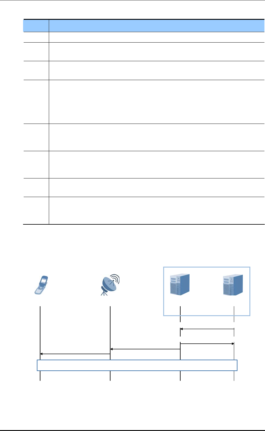
LTE eNB System Description/Ver.1.0
Step Description
1 The UE runs the Random Access process with the eNB.
2-4 The UE includes the SERIVCE REQUEST message, which is an NAS message, in the
RRC message that will be sent to the eNB, and sends it to the MME.
5 The eNB includes the SERVICE REQUEST message in the INITIAL UE message,
which is an S1-AP message, and passes it to the MME.
6 If there is no UE context for the UE in the network, the integrity is not protected for the
ATTACH REQUEST message, or the integrity check fails, an authentication and an
NAS security setup are always performed. The UE carries out the EPS AKA procedure
(TS 33.401, 6.1.1) with the MME. The MME establishes an NAS security association
with the UE using the NAS SMC process (TS 33.401, 7.2.4.4).
7 The MME sends the INITIAL CONTEXT SETUP REQUEST message, which is an S1-
AP message, to the eNB. This step activates radio and S1 bearers for all active EPS
bearers.
8-11 The eNB sets up the RRC radio bearers. The user plane security is established at this
step. The uplink data from the UE can now be passed by the eNB to the S-GW.
The eNB sends the uplink data to the S-GW, which, in turn, passes it to the P-GW.
12 The eNB sends the INITIAL CONTEXT SETUP RESPONSE message, which is an S1-
AP message, to the MME.
13-14 The MME sends the Modify Bearer Request message per PDN connection to the S-GW.
The S-GW can now send the downlink data to the UE, and sends Modify Bearer
Response to the MME.
Service Request by Networking
The message flow diagram below shows the Service Request process by networking.
UE eNB
EPC
3) PAGING Acknowled
g
e
1) Downlink Data Notification
S-GW MME
2) Downlink Data Notification
4) Paging
5) UE triggered Service Request procedure
Figure 4.3 Service Request Process by Networking
© SAMSUNG Electronics Co., Ltd. 4-5
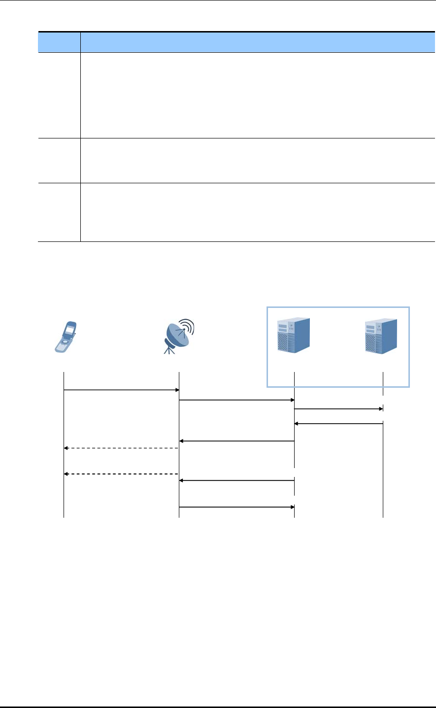
CHAPTER 4. Message Flows
Step Description
1-2 When the S-GW receives downlink data packets for a UE whose user plane is not
connected, it sends the Downlink Data Notification message to the MME which has the
control plane connection with the UE. The MME replies to the S-GW with the Downlink
Data Notification Acknowledge message. The S-GW stores additional downlink data
packets for the UE when it receives them. In this case, it does not send a new Downlink
Data Notification message.
3-4 When the UE is registered to the MME, the MME sends the PAGING message to all
eNBs that belong to the trace area where the UE is registered. When the eNB receives
the PAGING message from the MME, the eNB sends the Paging message to the UE.
5 When the UE in Idle mode receives the PAGING message via the E-UTRAN
connection, the Service Request procedure initiated by the UE is started. The S-GW
sends the downlink data to the UE via the RAT which has performed the Service
Request procedure.
Detach Initiated by the UE
The figure below shows the message flow of the Detach procedure initiated by the UE.
9) UE Context Release Complete
UE eNB MME S-GW
5) Downlink NAS Transport
(Detach Accept)
(Detach)
8) RRCConnectionRelease
(Detach Accept)
6) DLInformationTransfer
7) UE Context Release Command
3) Delete Session Request
2) Uplink NAS Transport
(Detach Request)
4) Delete Session Response
1) ULInformationTransfer
EPC
Figure 4.4 Detach Process by UE
4-6 © SAMSUNG Electronics Co., Ltd.

LTE eNB System Description/Ver.1.0
Step Description
1-2 The UE sends the DETACH REQUEST message, which is an NAS message, to the
MME. This NAS message is used to start setting up an S1 connection when the UE is in
Idle mode.
3 The active EPS bearers and their context information for the UE and MME which are in
the S-GW are deactivated when the MME sends the Delete Session Request message
for each PDN connection.
4 When receiving the Delete Session Request message from the MME, the S-GW
releases the related EPS bearer context information and replies with the Delete Session
Response message.
5-6 If the detach procedure has been triggered due to other reason except for the case that
the power of the UE was turned off, the MME sends the DETACH ACCEPT message to
the UE.
7 The MME sets the Cause IE value of the UE CONTEXT RELEASE COMMAND
message to ‘Detach’ and sends this message to the eNB to release the S1-MME
signaling connection to the UE.
8 If the RRC connection has not yet been released, the eNB sends the
RRCConnectionRelease message to the UE in Requested Reply mode. Once a reply to
this message is received from the UE, the eNB removes the UE context.
9 The eNB returns the UE CONTEXT RELEASE COMPLETE message to the MME to
confirm the S1 release. This releases the signaling connection between the MME and
ENB for the UE. This step must be performed immediately following step 7.
© SAMSUNG Electronics Co., Ltd. 4-7
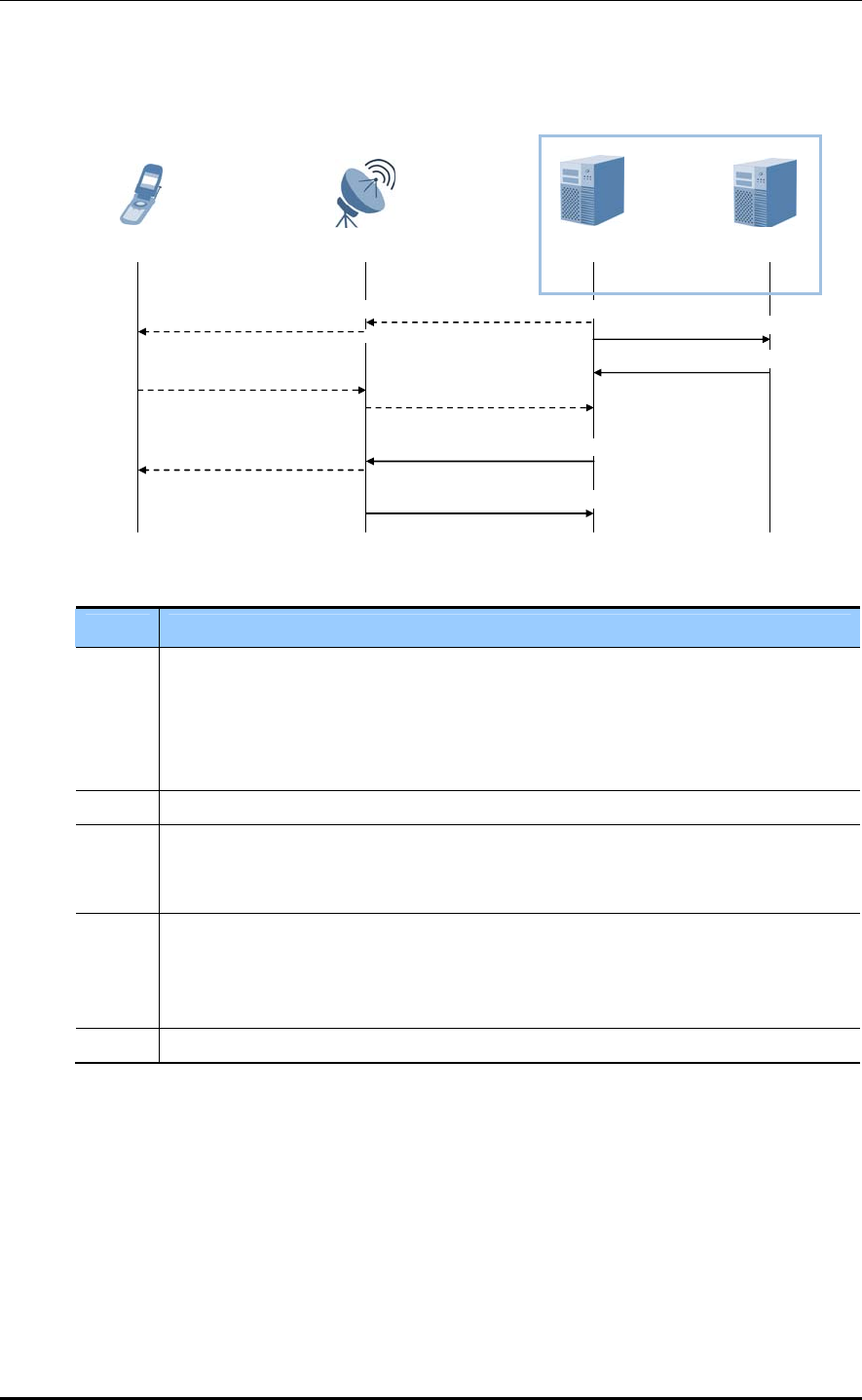
CHAPTER 4. Message Flows
Detach Initiated by the MME
The figure below shows the message flow of the Detach procedure initiated by the MME.
UE eNB MME S-GW
3) Delete Session Request
6) UPLINK NAS TRANSPORT
(Detach Accept)
9) UE Context Release Complete
4) Delete Session Response
1) DOWNLINK NAS TRANSPORT
(DETACH REQUEST)
7) UE Context Release Command
(Detach)
2) DLInformationTransfer
(Detach Request)
8) RRCConnectionRelease
5) ULInformationTransfer
(Detach Accept)
EPC
Figure 4.5 Detach Process by MME
Step Description
1-2 The MME detaches the UE implicitly if there is no communication between them for a
long time.
In case of the implicit detach, the MME does not send the DETACH REQUEST
message to the UE. If the UE is in the connected status, the MME sends the DETACH
REQUEST message to the UE to detach it explicitly.
3-4 These steps are the same as Step 3 and 4 in ‘Detach Procedure by UE’.
5-6 When the UE receives the DETACH REQUEST message from the MME in Step2, the
UE sends the DETACH ACCEPT message to the MME. The eNB transmits this NAS
message to the MME.
7 After receiving both of the DETACH ACCEPT message and the Delete Session
Response message, the MME sets the Cause IE value of the UE CONTEXT RELEASE
COMMAND message to ‘Detach’ and sends this message to the eNB to release the S1
connection to the UE.
8-9 These steps are the same as Step 8 and 9 in ‘Detach Procedure by UE’.
4-8 © SAMSUNG Electronics Co., Ltd.
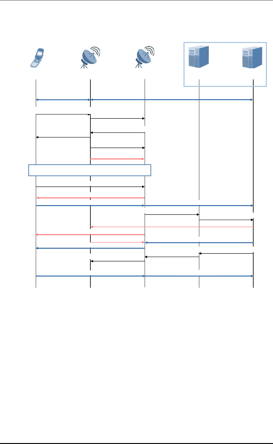
LTE eNB System Description/Ver.1.0
LTE Handover-X2-based Handover
The figure below shows the message flow of the X2-based Handover procedure.
UE Source eNB MME S-GW
EPC
1) MeasurementReport
Down/Uplink data Down/Uplink data
3) Handover Request Acknowledge
5) SN Status Transfer
4) RRCConnection-
Reconfiguration
(mobilityControlinfo)
Data forwarding
6
)
S
y
nchronization/UL allocation and timin
g
7) RRCConnectionReconfigurationComplete
Forwarded data
Uplink data
Forwarded data
Downlink data
Uplink data
Downlink data
8) Path Switch Request 9) Modify Bearer Request
End marker
End marker
10) Modify Bearer Response
12) UE Context Release
2) Handover Request
Request
Acknowledge
11) Path Switch
Target eNB
Downlink/Uplink data
Downlink/Uplink data
Figure 4.6 X2-based Handover Process
© SAMSUNG Electronics Co., Ltd. 4-9

CHAPTER 4. Message Flows
Step Description
1 The UE sends the Measurement Report message according to the system information,
standards and rules.
The UE sends the Measurement Report message according to the system information,
standards and rules.
2 The source eNB sends the target eNB a HANDOVER REQUEST message containing
the information required for handover. The target eNB can perform management control
in accordance with the received E-RAB QoS information.
3-4 The target eNB prepares the handover and creates an RRCConnectionReconfiguration
message, containing the mobileControlInfo IE that tells the source eNB to perform the
handover. The target eNB includes the RRCConnectionReconfiguration message in the
HANDOVER REQUEST ACKNOWLEDGE message, and sends it to the source eNB.
The source eNB sends the UE an RRCConnectionReconfiguration message, containing
the needed parameter values to command it to perform the handover.
5 To send the uplink PDCP SN receiver status and the downlink PDCP SN transmitter
status of the E-RABs of which the PDCP status must be preserved, the source eNB
sends the SN STATUS TRANSFER message to the target eNB.
6 After receiving the RRCConnectionReconfiguration message containing
mobileControlInfo IE, the UE performs synchronization with the target eNB and
connects to the target cell via a Random Access Channel (RACH). The target eNB
replies with an allocated UL and a timing advance value.
7 After having connected to the target cell successfully, the UE notifies the target eNB that
the Handover procedure has been completed using an RRCConnection-
ReconfigurationComplete message.
8 The target eNB, using the PATH SWITCH REQUEST message, notifies the MME that
the UE has changed the cell.
9-10 The MME sends the Modify Bearer Request message to the S-GW. The S-GW changes
the downlink data path into the target eNB. The S-GW sends at least one ‘end marker’
to the source eNB through the previous path, and releases the user plane resources for
the source eNB.
The S-GW sends a Modify Bearer Response message to the MME.
11 The MME sends the PATH SWITCH REQUEST ACKNOWLEDGE message to
acknowledge the PATH SWITCH REQUEST message.
12 The target eNB sends the UE CONTEXT RELEASE message to the source eNB to
notify the handover has succeeded and to make the source eNB release its resources.
When receiving the UE CONTEXT RELEASE messages, the source eNB released the
radio resource and the control plane resource related to the UE context.
4-10 © SAMSUNG Electronics Co., Ltd.
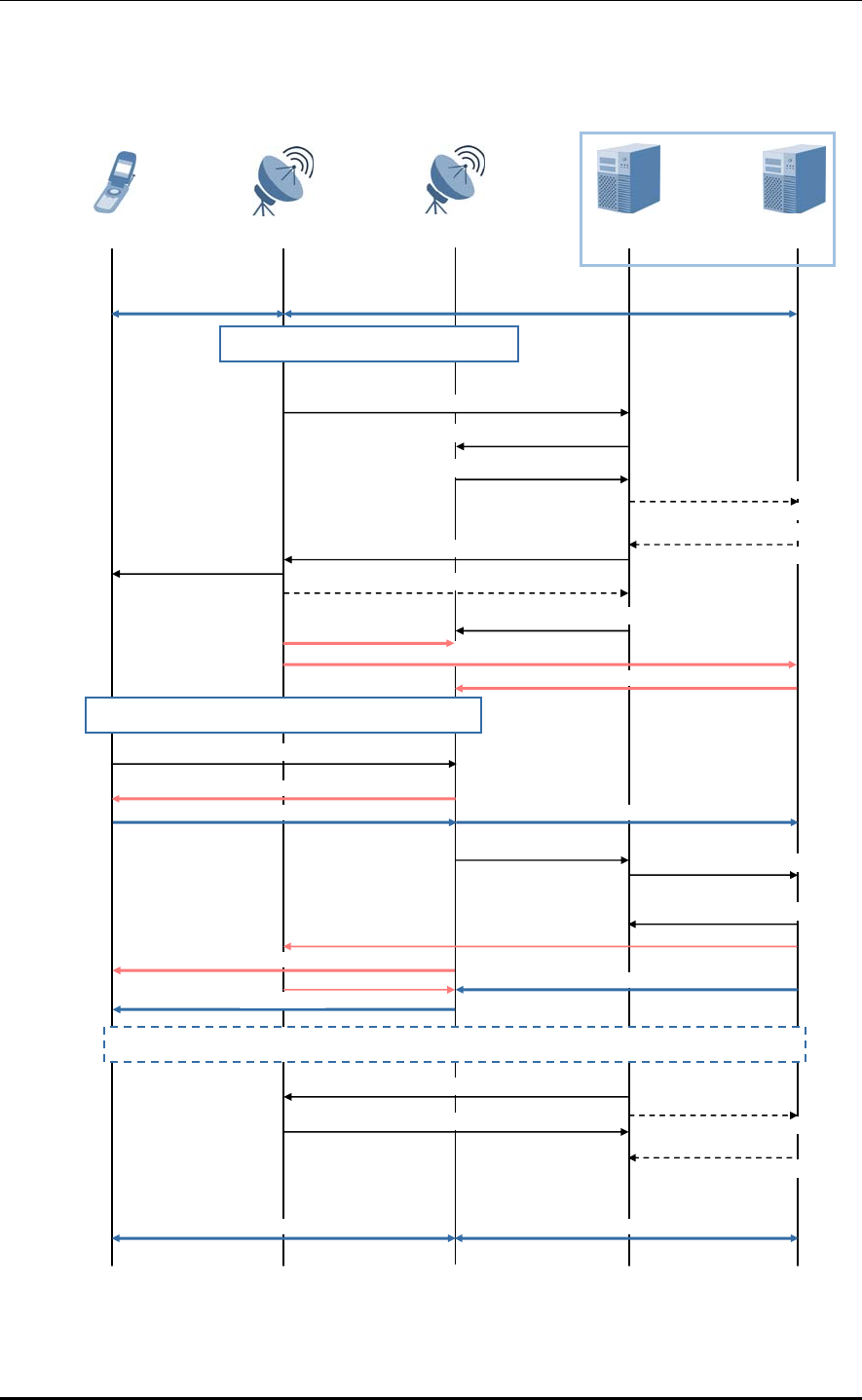
LTE eNB System Description/Ver.1.0
LTE Handover-S1-based Handover
The figure below shows the message flow of the S1-based Handover procedure.
UE Source eNB MME S-GW
EPC
Target eNB
Downlink/Uplink data Downlink/Uplink data
3) Handover Request
5) Create Indirect Data
Forwarding Tunnel Request
17) UE Context Release Command
18) UE Context Release Complete 19) Delete Indirect Data
Forwarding Tunnel Request
20) Delete Indirect Data
Forwarding Tunnel Response
Downlink/Uplink data Downlink/Uplink data
16
)
Trackin
g
Area U
p
date
p
rocedure
8) RRCConnection-
Reconfiguration
(mobilityControlinfo)
1) Direct data forwarding
1
)
Decision to tri
gg
er a relocation via
2) Handover Required
Indirect data forwarding
Downlink data
Downlink data
15) Modify Bearer Response
6) Create Indirect Data
Forwarding Tunnel Response
7) Handover Command
9) eNB Status Transfer
10) MME Status Transfer
2) Indirect data forwarding
11
)
Detach from old cell/S
y
nchronize to new cell
12) RRCConnectionReconfigurationComplete
Forwarded data
Uplink data Uplink data
13) Handover Notify 14) Modify Bearer Request
4) Handover Request
Acknowledge
End marker
Forwarded data
End marker
Figure 4.7 S1-based Handover Process
© SAMSUNG Electronics Co., Ltd. 4-11

CHAPTER 4. Message Flows
Step Description
1 The source eNB determines whether to perform S1-based handover into the target eNB.
The source eNB can make this decision when there is no X2 connection to the target or
when an error is notified by the target eNB after an X2-based handover has failed, or
based on the information the source eNB has obtained dynamically.
2 The source eNB sends the HANDOVER REQUIRED message to the MME. The source eNB
notifies the target eNB which bearer is used for data forwarding and whether forwarding
can be made directly from the source eNB to the target eNB.
3-4 The MME sends the HANDVER REQUEST message to the target eNB. This message
makes the target eNB to create a UE context containing the bearer-related information
and the security context.
The target eNB sends the HANDOVER REQUEST ACKNOWLEDGE message to the
MME.
5-6 If indirect forwarding is used, the MME sends the Create Indirect Data Forwarding
Tunnel Request message to the S-GW. The S-GW replies the MME with the Create
Indirect Data Forwarding Tunnel Response message.
7-8 The MME sends the HANDOVER COMMAND message to the source eNB. The source
eNB creates the RRCConnectionReconfiguration message using the Target to Source
Transparent Container IE value contained in the HANDOVER COMMAND message and
then sends it to the UE.
9-10 To send the PDCP status, and the HFN status of the E-RABs of which the PDCP status
must be preserved, the source eNB sends the eNB/MME STATUS TRANSFER message
to the target eNB via the MME. The source eNB must start forwarding the downlink data
to the target eNB through the bearer which was determined to be used for data
forwarding. This can be either direct or indirect forwarding.
11 The UE performs synchronization with the target eNB and connects to the target cell via
a RACH.
The target eNB replies with an allocated UL and a timing advance value.
12 After having synchronized with the target cell, the UE notifies the target eNB that the
Handover procedure has been completed using the
RRCConnectionReconfigurationComplete message. The downlink packets forwarded
from the source eNB cab be sent to the UE.
The uplink packets can be also sent from the UE to the S-GW via the target eNB.
13 The target eNB sends the HANDOVER NOTIFY message to the MME. The MME starts
the timer which tells when the resources of the source eNB and the temporary resources
used by the S-GW for indirect forwarding will be released.
14 For each PDN connection, the MME sends the Modify Bearer Request message to the
S-GW. Downlink packets are sent from the S-GW to the target eNB immediately.
15 The S-GW sends the Modify Bearer Response message to the MME. As soon as the
target eNB changes the path to help packet reordering, the S-GW sends at least one
‘end marker’ packet to the source eNB through the previous path.
16 If any of the conditions listed in section 5.3.3.0 of TS 23.401 (6) are met, the UE starts
the Tracking Area Update procedure.
4-12 © SAMSUNG Electronics Co., Ltd.

LTE eNB System Description/Ver.1.0
(Continued)
Step Description
17-18 When the timer started at step 13 expires, the MME sends the UE CONTEXT RELEASE
COMMAND message to the source eNB. The source eNB releases the resources
related to the UE and replies to the target eNB with the UE CONTEXT RELEASE
COMPLETE message.
19-20 If indirect forwarding has been used, when the timer started at step 13 expires the MME
sends the Delete Indirect Data Forwarding Tunnel Request message to the S-GW.
This message gets the S-GW to release the temporary resources allocated for indirect
forwarding at step 5.
The S-GW replies to the MME with the Delete Indirect Data Forwarding Tunnel
Response message.
© SAMSUNG Electronics Co., Ltd. 4-13
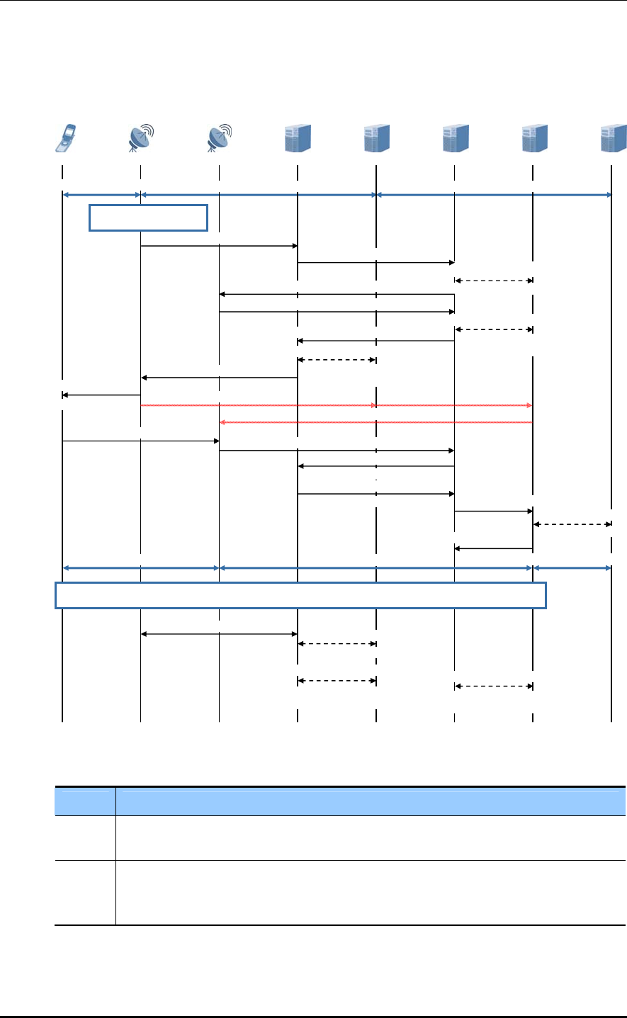
CHAPTER 4. Message Flows
Inter-RAT Handover-LTE to UTRAN PS Handover
Below is the message flow for the PS handover procedure from the E-UTRAN to the
UTRAN.
Figure 4.8 E-UTRAN-UTRAN PS Handover Process
Step Description
1 The source eNB determines the PS handover to the UTRAN. This handover can be
determined in accordance with the measurement report received from UE.
2 The source eNB sends the HANDOVER REQUIRED message to the MME. The source
eNB then puts the Source RNC to Target RNC Transparent Container IE information
into the message to transmit the information to the target RNC.
Downlink/Uplink data Downlink/Uplink data
1) Handover Initiation
2) Handover Required
3) Forward Relocation Request
4) Create Session
Request/Response
5) Relocation Request
6) Relocation Request Acknowledge
7) Create Indirect Data
Forwarding Tunnel
Request/Response
8) Forward Relocation Response
9) Create Indirect Data
10) Handover Command
E-UTRAN Command
11) Mobility From Indirect data forwarding
Indirect data forwarding
12) HO to UTRAN Complete 13) Relocation Complete
14) Forward Relocation Complete
Notification
15) Forward Relocation Complete
Acknowledge
17) Modify Bearer
Request/Response
18) Modify Bearer
Response Downlink/Uplink data
Downlink/Uplink data
Downlink/Uplink data
19) Routing Area Update procedure
20) S1 Release
Request/Response
21) Delete Session
22) Create Indirect Data
Forwarding Tunnel
Request/Response
23) Create Indirect Data
Forwarding Tunnel
Downlink/Uplink data
Forwarding Tunnel
Request/Response
16) Modify Bearer
Re
q
uest
Request/Response
P-GW Target S-GW Target SGSN Source MME Source S-GW Target RNS Source eNB UE
4-14 © SAMSUNG Electronics Co., Ltd.

LTE eNB System Description/Ver.1.0
(Continued)
Step Description
3-4 The source MME recognizes the handover from the target ID IE of the HANDVER
REQUIRED message to the UTRAN and sends the FORWARD RELOCATION
REQUEST message to the target SGSN. The target SGSN determines whether to
change the S-GW. Then if change is required, it carries out the Create Session
Request/Response procedure with a new S-GW.
5-6 The target SGSN transmits the RELOCATION REQUEST message to the target RNC
to request resource allocation for the target RNC. The target RNC carries out the CAC
and resource allocation for each RAB for which handover is requested, and transmits
the RELOCATION REQUEST ACKNOWLEDGE message containing the result to the
target SGSN to respond to the request. The Target RNC to Source RNC Transparent
Container IE to transmit to the source eNB is then contained.
7-9 To perform the forwarding tunnel setup, the target SGSN carries out the Create Indirect
Data Forwarding Tunnel Request/Response procedure with target S-GW and transmits
the FORWARD RELOCATION RESPONSE message to the source MME. To perform
the forwarding tunnel setup, the source MME carries out the Create Indirect Data
Forwarding Tunnel Request/Response procedure with the source S-GW.
10-11 The source MME sends the HANDOVER COMMAND message to the source eNB. By
doing so, the handover preparation procedure to the target UTRAN is completed.
The Source eNB configures the MOBILITY FROM E-UTRAN COMMAND containing the
Target RNC to Source RNC Transparent Container IE in the HANDOVER COMMAND
message and transmits it to the UE to request the PS handover to the UTRAN.
12 The UE performs synchronization with the target UTRAN and connects to the target cell
via a RACH.
After UE is successfully connected to the target cell, UE transmits the HANDOVER TO
UTRAN COMPLETE message to the target UTRAN to complete the handover
procedure.
13-15 The target RNC transmits the RELOCATION COMPLETE message to the target SGSN
to notify that the handover procedure from the UE to the UTRAN has been completed
successfully.
The target SGSN transmits the FORWARD RELOCATION COMPLETE NOTIFICATION
message to the source MME. At this time, the source MME operates the waiting timer
for releasing the resource of the E-UTRAN and transmits the FORWARD RELOCATION
COMPLETE ACKNOWLEDGE response message to the target SGSN. The target
SGSN operates the waiting timer for releasing the forwarding tunnel at the time when
the source MME receives the response message.
16-18 For each PDN connection, the target SGSN sends the Modify Bearer Request message
to the target S-GW. The downlink packet is then transmitted from the S-GW to the target
RNC. The target S-GW
carries out the Modify Bearer Request/Response procedure with the P-GW and
transmits the Modify Bearer Response message to the target SGSN.
19 When UE satisfies the conditions specified in section 5.5.2.1 of TS 23.401, the Routing
Area Update procedure starts.
20-23 When the timer of procedure 14 has expired, the source MME requests the resource
release procedure to be carried out on the source eNB and the source S-GW.
When the timer of procedure 15 has expired, the target SGSN carries out the resource
release allocated for the forwarding tunnel with the target S-GW.
© SAMSUNG Electronics Co., Ltd. 4-15
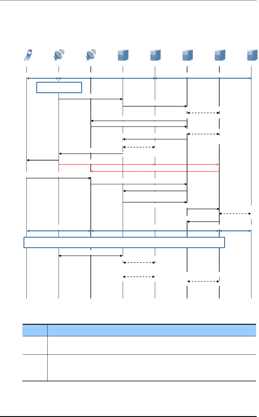
CHAPTER 4. Message Flows
Inter-RAT Handover-UTRAN to LTE PS Handover
Below is the message flow for the PS handover procedure from the UTRAN to the E-
UTRAN.
11) HO from UTRAN
UE Source RNC
Downlink/Uplink data
Target eNB Source SGSN Source S-GW Target MME Target S-GW P-GW
Downlink/Uplink data Downlink/Uplink data
1) Handover Initiation
2) Relocation Required
3) Forward Relocation Request
4) Create Session
Request/Response
5) Handover Request
6) Handover Request Acknowledge
7) Create Indirect Data
Forwarding Tunnel
Request/Response
8) Forward Relocation Response
Forwarding Tunnel
Request/Response
9) Create Indirect Data
10) Relocation Command
Command Indirect data forwarding
Indirect data forwarding
12) RRC Connection Reconfiguration Complete
13) Handover Notify
14) Forward Relocation Complete
Notification
15) Forward Relocation Complete
Acknowledge 17) Modify Bearer
Request/Response
18) Modify Bearer
Response Downlink/Uplink data Downlink/Uplink data Downlink/Uplink data
19) Tracking Area Update procedure
20) Iu Release
21) Delete Session
Request/Response
22) Delete Indirect Data
Forwarding Tunnel
Request/Response 23) Delete Indirect Data
Forwarding Tunnel
Request/Response
16) Modify Bearer
Request
Figure 4.9 UTRAN-E-UTRAN PS Handover Process
Step Description
1 The source RNC determines the PS handover to the E-UTRAN. This handover can be
determined in accordance with the measurement report received from UE.
2 The source RNC sends the RELOCATION REQUIRED message to the SGSN.
The source RNC then puts the Source eNB to Target eNB Transparent Container IE
information into the message to transmit the information to the target eNB.
4-16 © SAMSUNG Electronics Co., Ltd.

LTE eNB System Description/Ver.1.0
(Continued)
Step Description
3-4 The source SGSN recognizes the handover from the target ID IE of the RELOCATION
REQUIRED message to the E-UTRAN and sends the FORWARD RELOCATION
REQUEST message to the target MME. The target MME determines whether to change
the S-GW, if change is required, it carries out the Create Session Request/Response
procedure with a new S-GW.
5-6 The target MME transmits the HANDOVER REQUEST message to the target eNB to
request resource allocation for the target eNB. The target eNB carries out the CAC and
resource allocation for each RAB for which handover is requested, and transmits the
HANDOVER REQUEST ACKNOWLEDGE message containing the result to the target
MME to respond to the request. At this time, the Target eNB to Source eNB Transparent
Container IE to transmit to the source RNC is contained.
7-9 To perform the forwarding tunnel setup, the target MME carries out the Create Indirect
Data Forwarding Tunnel Request/Response procedure with target S-GW and transmits
the FORWARD RELOCATION RESPONSE message to the source SGSN. To perform
the forwarding tunnel setup, the source SGSN carries out the Create Indirect Data
Forwarding Tunnel Request/Response procedure with the source S-GW.
10-11 The source SGSN sends the RELOCATION COMMAND message to the source RNC.
By doing so, the handover preparation procedure to the target E-UTRAN is completed.
The source RNC configures the Handover FROM UTRAN COMMAND message
containing the Target eNB to Source eNB Transparent Container IE in the
RELOCATION COMMAND message and transmits it to UE to request the PS handover
to the E-UTRAN.
12 The UE performs synchronization with the target E-UTRAN and connects to the target
cell via a RACH.
After UE is successfully connected to the target cell, UE transmits the RRC
CONNECTION RECONFIGURATION COMPLETE message to the target E-UTRAN to
complete the handover procedure.
13-15 The target eNB then transmits the HANDOVER NOTIFY message to the target MME
to notify that the handover procedure to the E-UTRAN has been completed
successfully. The target MME transmits the FORWARD RELOCATION COMPLETE
NOTIFICATION message to the source SGSN. At this time, the source SGSN operates
the waiting timer for releasing the resource of the UTRAN and transmits the FORWARD
RELOCATION COMPLETE ACKNOWLEDGE response message to the target MME.
The target MME operates the waiting timer for releasing the forwarding tunnel at the
time when the source SGSN receives the response message.
16-18 For each PDN connection, the target MME sends the Modify Bearer Request message
to the target S-GW. The downlink packet is then transmitted from the S-GW to the target
eNB. The target S-GW carries out the Modify Bearer Request/Response procedure with
the P-GW and transmits the Modify Bearer Response message to the target MME.
19 When UE satisfies the conditions specified in section 5.5.2.2 of TS 23.401, the Tracking
Area Update procedure starts.
20-23 When the timer of procedure 14 has expired, the source SGSN requests the resource
release procedure to be carried out on the source RNC and the source S-GW.
When the timer of procedure 15 has expired, the target MME carries out the resource
release allocated for the forwarding tunnel with the target S-GW.
© SAMSUNG Electronics Co., Ltd. 4-17
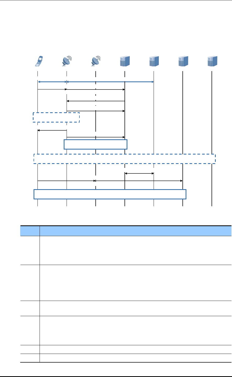
CHAPTER 4. Message Flows
CS Fallback to UTRAN
Below is the message flow for the CS Fallback process from the E-UTRAN to the UTRAN.
The procedure below shows that the CS Fallback process is carried out through redirection
processing to the UTRAN without PS HO when UE, which is in RRC Connected status,
sends the CS call.
Figure 4.10 CS Fallback to UTRAN Process (UE in Active Mode, No PS HO Support)
Step Description
1 When an RRC Connected UE in the E-UTRAN requests a CS call, it creates an EXTENDED
SERVICE REQUEST message (NAS) containing the CS fallback indicator, and sends it
to the network. The UE uses an RRC UL INFORMATION TRANSFER message.
The eNB sends this to the MME using a UL NAS TRANSPORT message.
2-3 The MME prepares an S1AP message (UE CONTEXT MODIFICATION REQUEST)
containing the CS fallback indicator, and sends it to the eNB to request CS fallback
handling.
The eNB transmits a response message (UE CONTEXT MODIFICATION RESPONSE)
appropriate for Process 2 to the MME.
4 The eNB can instruct the UE to measure the target RAT if it needs the UE’s
measurement for CS fallback handling (optional).
5 The eNB uses a redirection process for a CS fallback to UTRAN.
The eNB includes redirected carrier information on the target UTRAN in the RRC
CONNECTION RELEASE message to send to the UE. The UE redirects to the UTRAN
based on the redirected carrier information instructed by the eNB.
6 The eNB transmits the UE CONTEXT RELEASE REQUEST message to the MME.
7 The MME carries out the procedure for releasing the UE context of the E-UTRAN.
SGSN MSC S/P-GW MME Target RNS
Downlink/U
p
link data Downlink/Uplink data
4) UE Measurement
Solicitation (Optional)
2) S1AP Request Message
3) S1AP Response Message
1) UL Information Transfer/UL NAS Transport
6) UE Context Release Request
Release
5) RRC Connection
8) UE changes RAT then LAU or Combined RA/LA update or RAU or LAU and RAU
(Extended Service Request)
With CS Fallback indicator
7) S1 Release
9) Update bearer (s)
10) RRC/Iu-CS messages
(CM Service Request)
CS Call Setup
Source eNB UE
4-18 © SAMSUNG Electronics Co., Ltd.
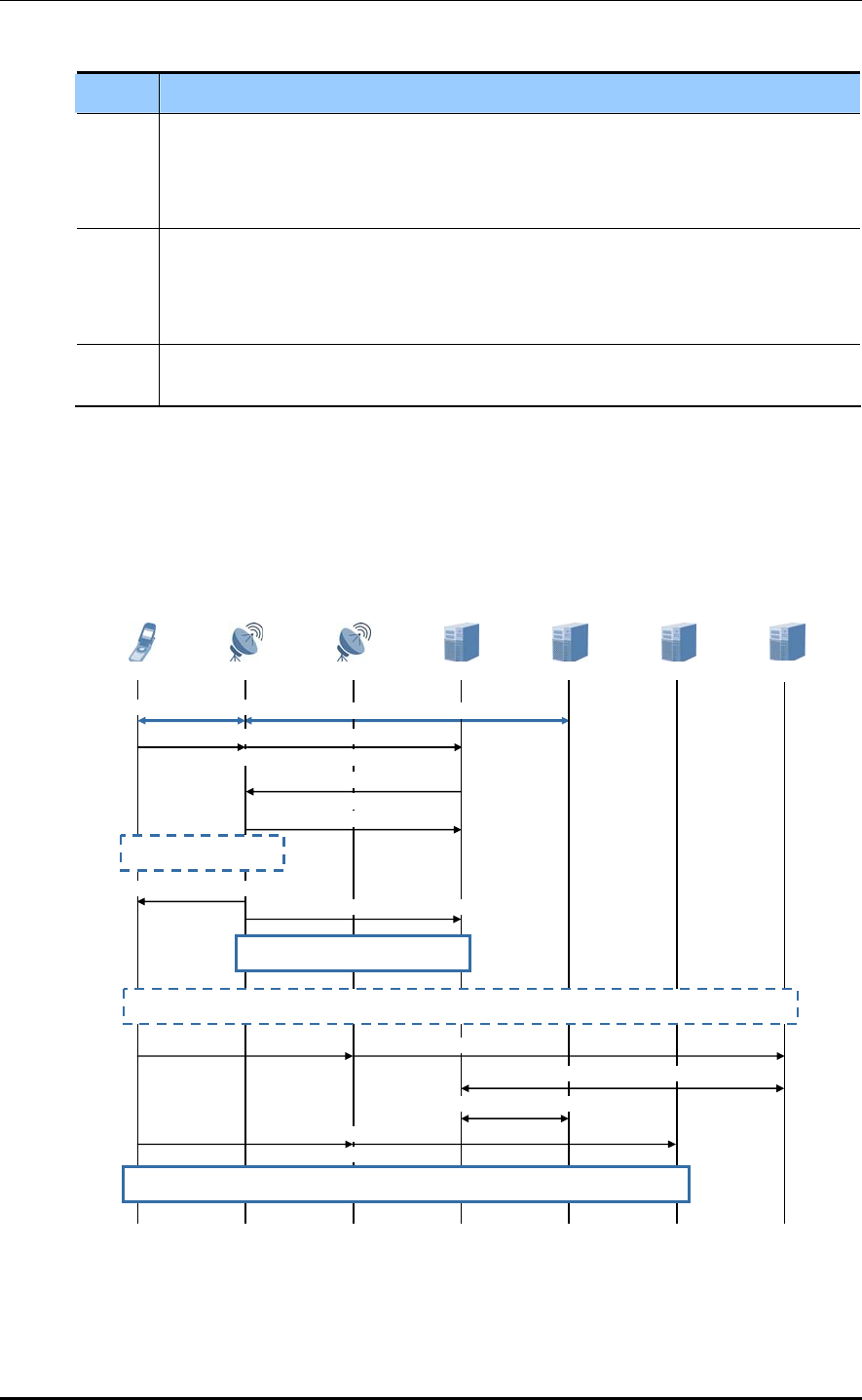
LTE eNB System Description/Ver.1.0
(Continued)
Step Description
8 After connecting to the UTRAN, UE transmits the RRC INITIAL DIRECT TRANSFER
message to set the CS signaling connection. If the LA or RA of the connected UTRAN
cell is different from the stored information, the location registration procedure (LAU
and/or RAU or combined LAU/RAU) is carried out.
9 After receiving the UE CONTEXT RELEASE REQUEST message in Procedure 6, the
MME carries out the suspension processing of the non-GBR bearer (s) of the S-GW/P-
GW and the deactivation processing of the GBR bearer (s).
Afterward, the MME manages the UE context in the suspended status.
10 The UE transmits the CM SERVICE REQUEST message to the UTRAN to carry out
next procedure for the CS call setup.
CS Fallback to GERAN
Below is the message flow for the CS Fallback procedure from the E-UTRAN to the
GERAN. The procedure below shows that the CS Fallback procedure is carried out through
Cell Change Order processing to the GERAN without PS HO when a UE which is in the
RRC_Connected status sends the CS call.
UE
Figure 4.11 CS Fallback to GERAN Process (UE in Active Mode, No PS HO Support)
Source eNB
Downlink/Uplink data
Target BSS MME S/P-GW MSC
Downlink/Uplink data
4) UE Measurement
Solicitation (Optional)
2) S1AP Request Message
3) S1AP Response Message
1) UL Information Transfer/UL NAS Transport
6) UE Context Release Request
UTRA Command
5) Mobility from E-
8) UE changes RAT then LAU or Combined RA/LA update or RAU or LAU and RAU
(Extended Service Request)
With CS Fallback Indicator
7) S1 Release
11) Update bearer (s)
12) RRC/Iu-CS messages
(CM Service Request)
CS Call Setup
10) Suspend Request/Response
9) Suspend
SGSN
© SAMSUNG Electronics Co., Ltd. 4-19

CHAPTER 4. Message Flows
Step Description
1 When an RRC Connected UE in the E-UTRAN requests a CS call, it creates an
EXTENDED SERVICE REQUEST message (NAS) containing the CS fallback indicator,
and sends it to the network. The UE uses an RRC UL INFORMATION TRANSFER
message.
The eNB sends this to the MME using a UL NAS TRANSPORT message.
2-3 The MME prepares an S1AP message (UE CONTEXT MODIFICATION REQUEST)
containing the CS fallback indicator, and sends it to the eNB to request CS fallback
handling.
The eNB transmits a response message (UE CONTEXT MODIFICATION RESPONSE)
appropriate for Process 2 to the MME.
4 The eNB can instruct the UE to measure the target RAT if it needs the UE’s
measurement for CS fallback handling (optional).
5 The eNB uses the Cell Change Order procedure for the CS Fallback processing to the
GERAN.
The eNB transmits the MOBILITY FROM E-UTRA COMMAND message containing the
PCI and carrierFreq which is applicable to the GERAN target cell to the UE.
The UE carries out the cell change order procedure on the GERAN target cell specified
by the eNB.
6 The eNB transmits the UE CONTEXT RELEASE REQUEST message to the MME.
7 The MME carries out the procedure for releasing the UE context of the E-UTRAN.
8 After connecting to the GERAN, the UE carries out the RR connection setup procedure.
If the LA or RA of the connected GERAN cell is different from the stored information, the
location registration procedure (LAU and/or RAU or combined LAU/RAU) is carried out.
9-10 When the UE or the target GERAN cell does not support the Dual Transfer Mode
(DTM), the UE starts the Suspend procedure. When the Suspend request is received
from the UE, the SGSN processes the Suspend Request/Response procedure with the
MME.
11 The MME carries out the suspension processing for the non-GBR bearer (s) of the S-
GW/P-GW and the deactivation processing of the GBR bearer (s). Afterward, the MME
manages the UE context in the suspended status.
12 The UE transmits the CM SERVICE REQUEST message to the UTRAN to carry out
next procedure for the CS call setup.
4-20 © SAMSUNG Electronics Co., Ltd.
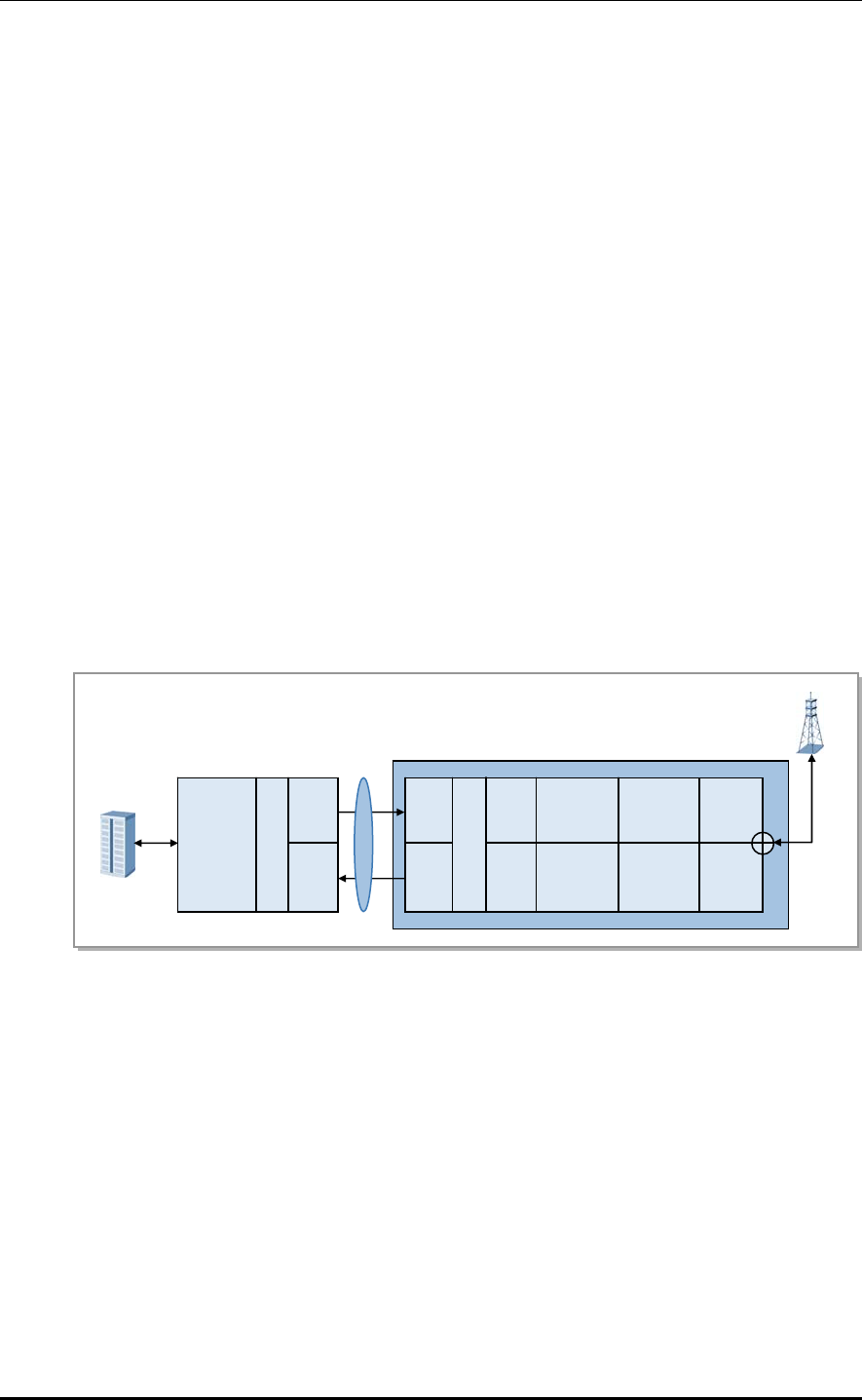
LTE eNB System Description/Ver.1.0
4.2 Data Message Flow
Sending Path
The user data received from the EPC is transmitted to the eNB UADU through the Ethernet
switch after passing the network interface module. The transmitted user data goes through
baseband-level digital processing before being configured for the CPRI, and then E/O
converted. The converted signal is transmitted to the L8HU that is located remotely
through an optic cable. L8HU operates the O/E conversion on the transmitted optic signal.
The converted baseband signal from the broadband is converted into an analog signal and
sent through the high-power amplifier, filter and antenna.
Receiving Path
The RF signal received by the antenna goes through the L8HU filter and low-noise
amplification by the LNA.
This signal is then converted into a baseband signal after RF down-conversion and digital
down-conversion. It is configured for the CPRI, and goes through E/O conversion again.
The converted signal is transmitted to the UADU that is located remotely through an optic
cable. The data for which the SC-FDMA signal processing is carried out in the UADU is
converted to the Gigabit Ethernet frame and transmitted from the UADU to the EPC via the
GE/FE.
L8HU
Figure 4.12 eNB System Control and Traffic Flow
Main
Processor
&
Channel
Card
C
P
R
I
Con
ver
sion
E/O
O/E
GE/FE
UADU
Optic CPRI
E/O
O/E
A/D
D/A
C
P
R
I
Con
ver
sion
DOWN
Conversion
UP
Conversion
LNA
Power
Amp
Rx
Filte
r
Tx
Filte
r
EPC
© SAMSUNG Electronics Co., Ltd. 4-21
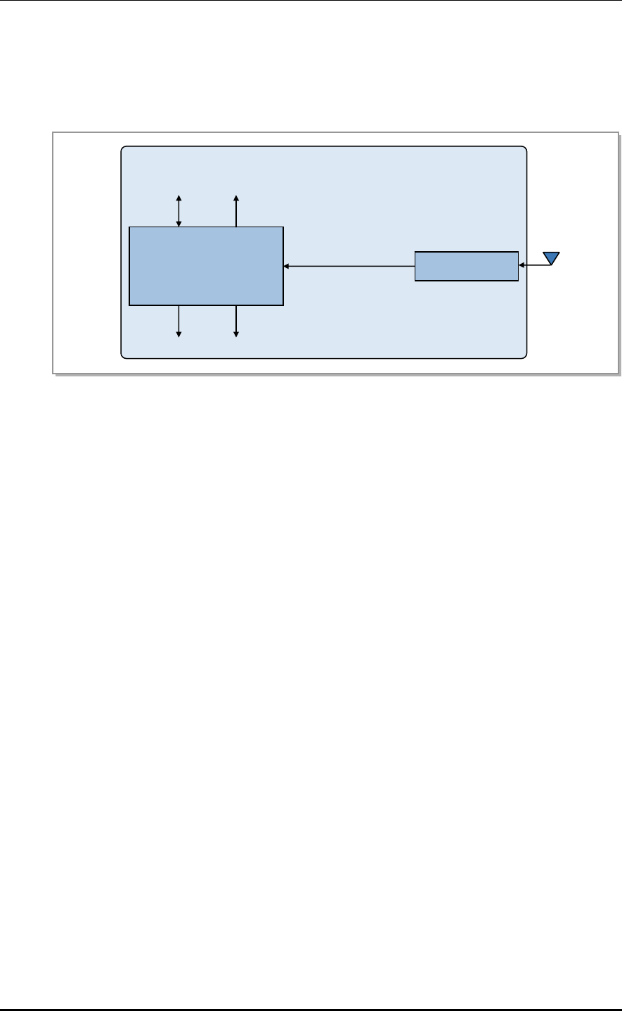
CHAPTER 4. Message Flows
4.3 Network Synchronization Flow
The eNB uses GPS to synchronize the system. The UCCM is a GPS receiving module in
the UADU, and receives synchronization signals from the GPS to generate/distribute clocks.
SYS (System Clock 30.72 MHz) UADU
SFN (System Frame Number)
PP2S (Even Clock)
Control
Figure 4.13 eNB Network Synchronization Flow
Clock
Generation & Distribution UCCM
1 pps Analog 10 MHz
Test equipment
Digital 10 MHz GPS
PP2S (Even Clock)
4-22 © SAMSUNG Electronics Co., Ltd.
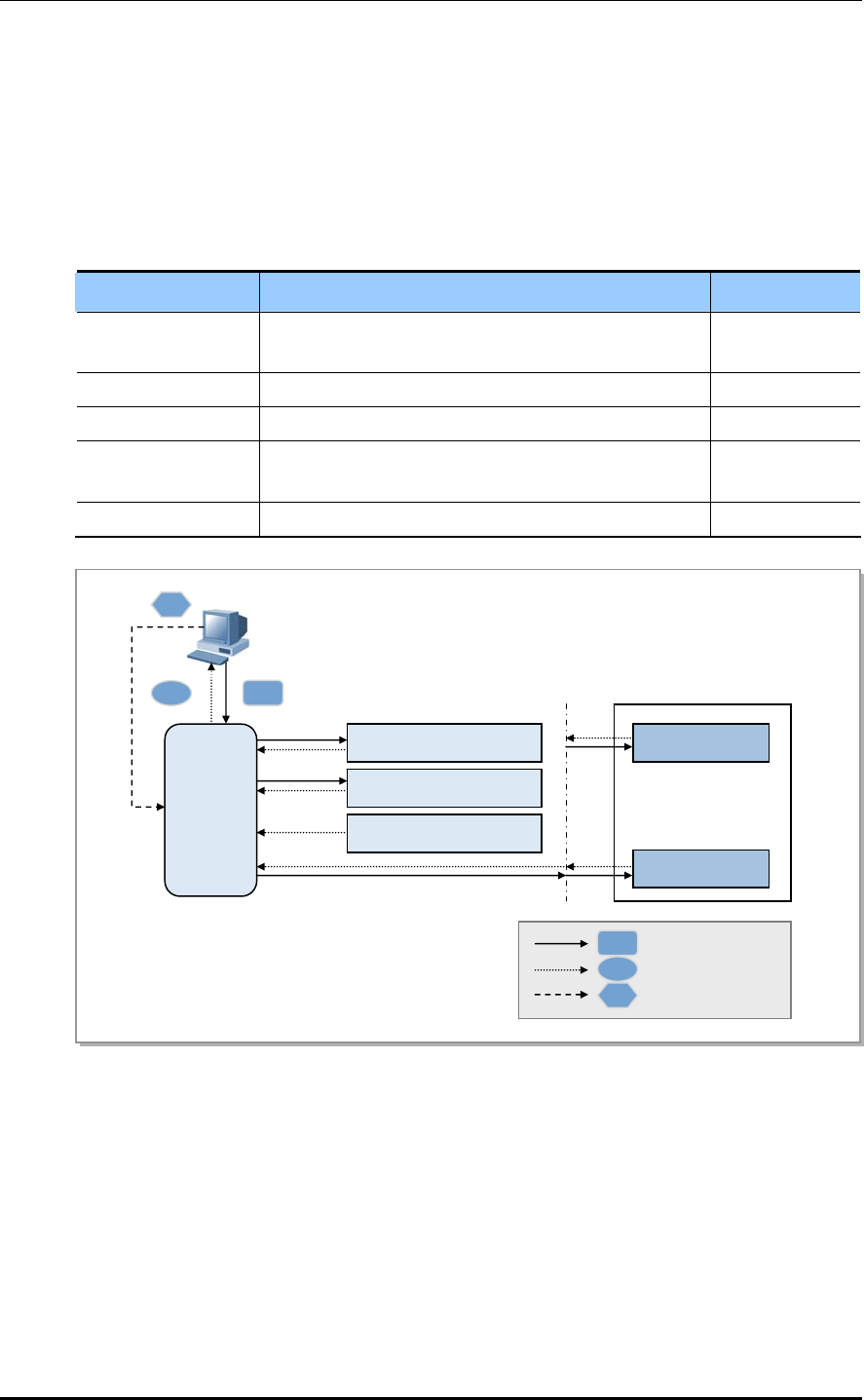
LTE eNB System Description/Ver.1.0
© SAMSUNG Electronics Co., Ltd. 4-23
4.4 Alarm Signal Flow
An environmental fault or hardware mount/dismount is reported with an alarm signal,
which is collected by the UAMA of the UADU, and then reported to the LTE system
manager (LSM). The user can provide custom alarms through the UDA and environmental
alarms (flood, door, fire, temperature, etc.) through the ECM, and control the FAN in the rack.
The following alarms are collected by the UAMA:
Alarm Type Description Target to Apply
Function Fail Alarm Fault alarm due to software/hardware problems defined
as ‘function fail’
L9CA, UAMA
Power Fail Alarm Fault alarm due to power problems L9CA, UAMA
Deletion Alarm System report alarm due to hardware mount/dismount L9CA
Environmental Fault
Alarm
Alarms for the rectifier, flood, fire, FANM-B2, door,
control, etc.
System
UDA Custom Alarm by the operator UAMA
Figure 4.14 eNB System Alarm Flow
UAMA
L9CA
GPS Module (in UAMA)
ECM
L8HU #120
L8HU #0
: Reset
: Alarm
: Remote Pattern Reset
LSM
C
B
A
A
B
C
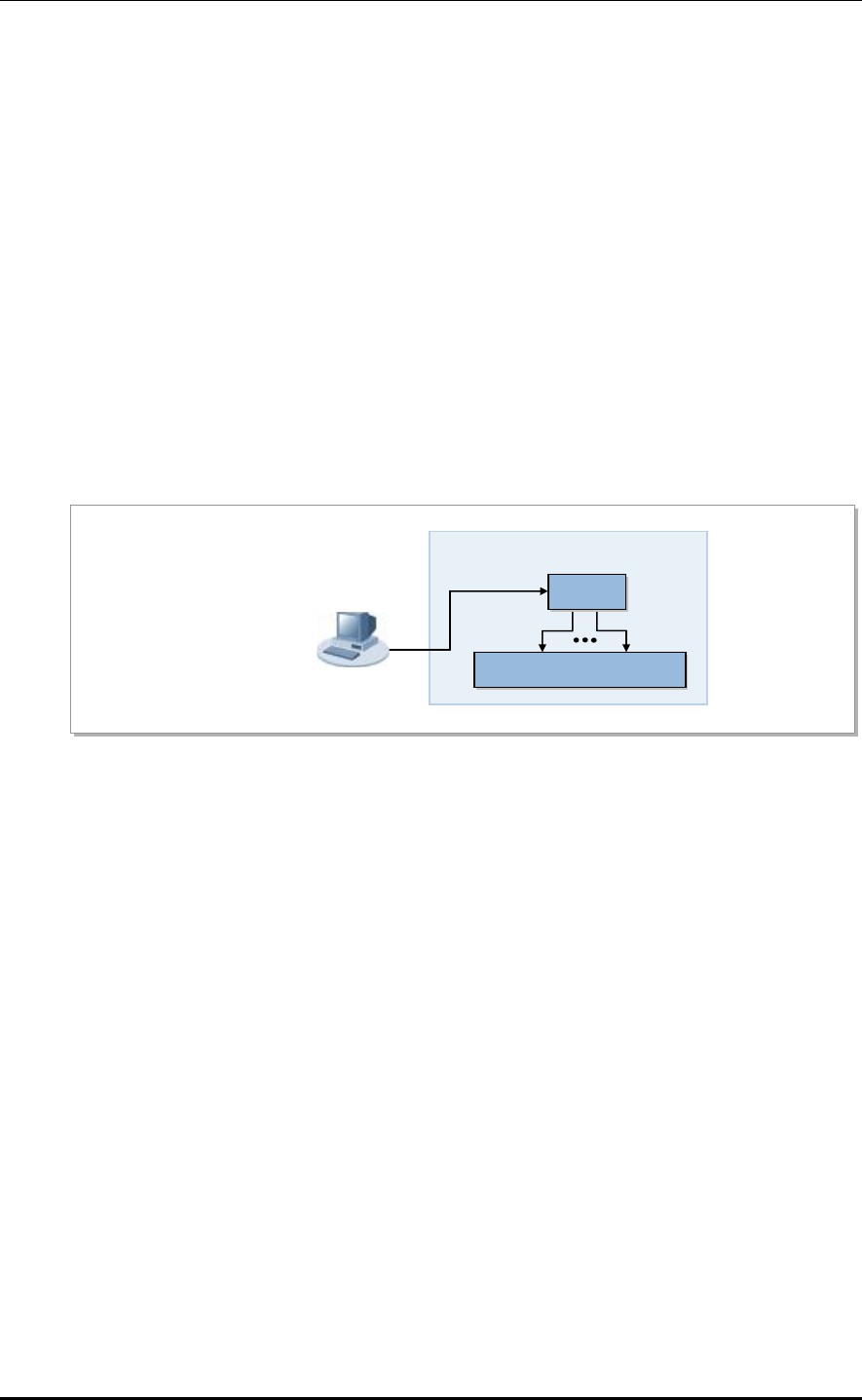
CHAPTER 4. Message Flows
4.5 Loading Flow
Loading is a process that downloads, from the LSM, software executables, data, etc.
required by the eNB’s processors and devices to operate.
The eNB’s loading is run during system initialization. Loading can also be run when a
board is mounted on the system, hardware is reset, or the high-level system operator
restarts a board.
On the first system initialization, the eNB is loaded through the LSM. As the loading
information is stored in the internal storage, no unnecessary loading is carried out afterward.
When comparing versions after initialization, if the information stored in the internal
storage is the latest information, remote loading is not carried out.
The loading information contains the software image and default configuration information
file, etc.
eNB
Figure 4.15 Loading Signal Flow
UAMA
Sub-processor
LSM
4-24 © SAMSUNG Electronics Co., Ltd.
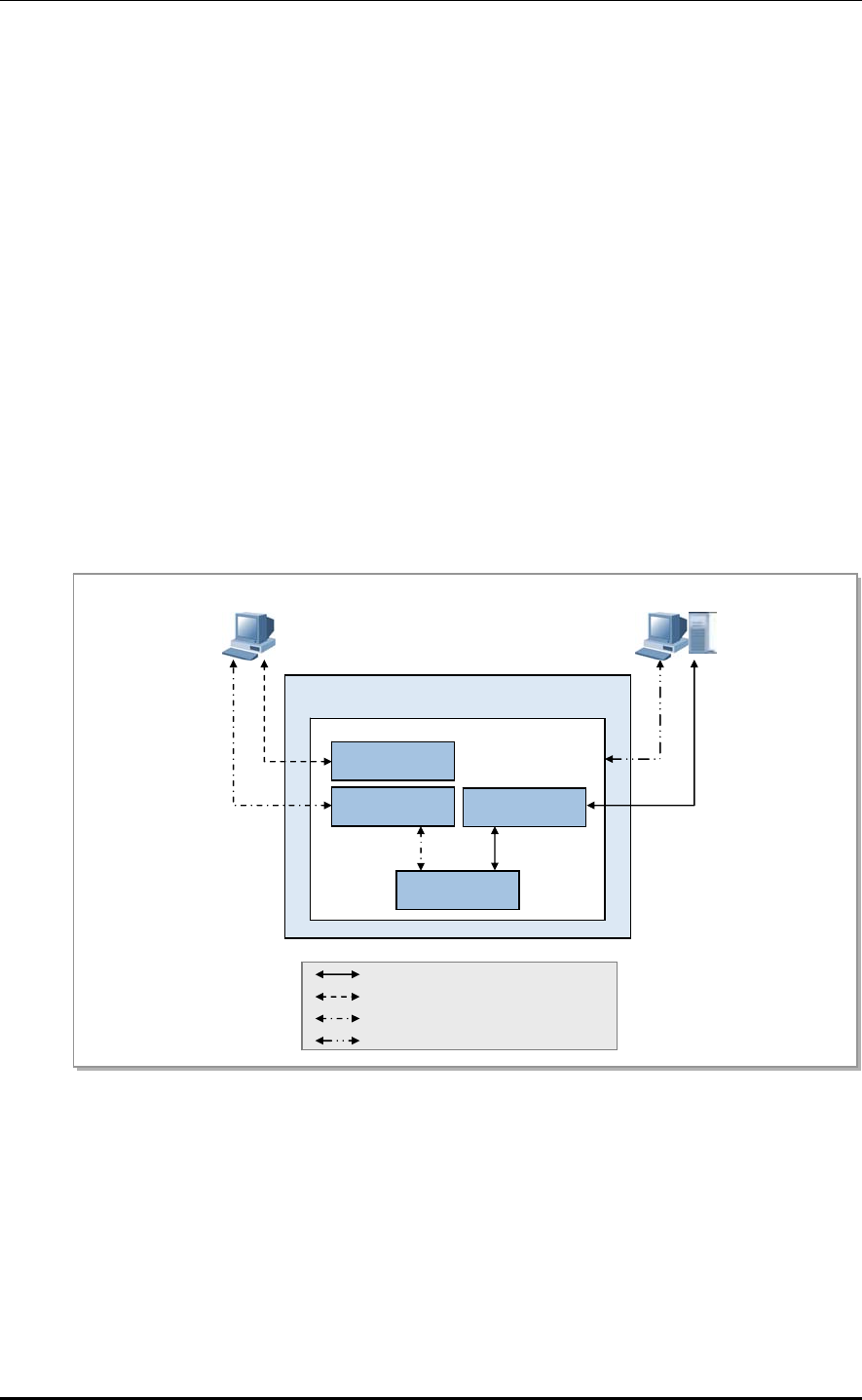
LTE eNB System Description/Ver.1.0
4.6 Operation and Maintenance Message Flow
The operator can view/change the eNB status through the system manager. To do this, the
eNB has an SNMP agent through which the LSM operator can run eNB operations and
maintenance remotely. The operator can also perform Web-EMT-based maintenance
activities using the web browser in the console terminal or through the CLI using
telnet/SSH access.
The statistical information provided by the eNB is given to the operator in accordance with
the collection interval.
Operation and Maintenance Message Flow
The eNB operation and maintenance occur through SNMP messages between the SNMP
agent in the main OAM and the LSM’s SNMP manager.
The eNB processes various messages from the LTE’s SNMP manager, and reports the
results back to the manager as well as reporting real time if events such faults or status
changes occur. The operation and maintenance signal flow is shown below.
Web-EMT (HTTP Client)/CLI LSM (SNMP Manager)
eNB
UAMA
HTTP Server
CLI SNMP
Other Block
SNMP message
HTTP message (command/response)
CLI command
Statistical Data
Figure 4.16 Operation and Maintenance Signal Flow
© SAMSUNG Electronics Co., Ltd. 4-25

CHAPTER 4. Message Flows
This page is intentionally left blank.
4-26 © SAMSUNG Electronics Co., Ltd.
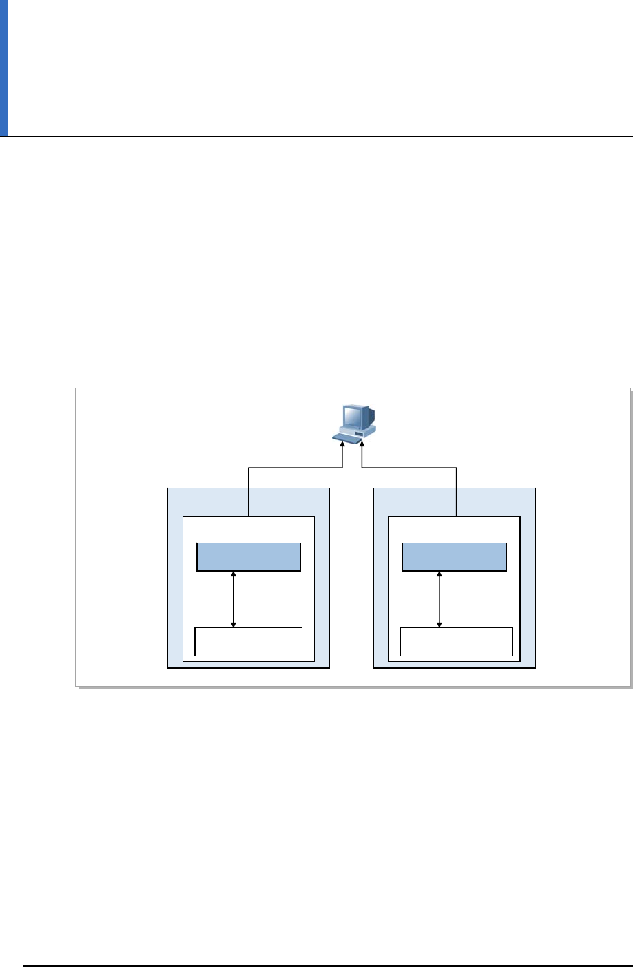
LTE eNB System Description
CHAPTER 5. Supplementary
Functions and Tools
5.1 Web-EMT
The Web-EMT is a GUI-based console terminal and tool for device-monitoring, operation,
and maintenance through direct access to the eNB. The operator can run the Web-EMT
using Internet Explorer, without installing additional software. The GUI is provided using
the HTTPs protocol internally.
Figure 5.1 Web-EMT Interface
The operator can use the Web-EMT to restart the eNB or internal boards, view/set
configuration and operation parameters, monitor statuses and faults, and run a diagnosis.
However, increasing/decreasing resources or changing operational information on neighbor
lists is possible only through the LSM which manages the entire network and loaded image.
eNB
UAMA
HTTP Server
Other Block
OAM
command/
response
eNB
HTTP message HTTP message
UAMA
HTTP Server
OAM
command/
response
…Other Block
© SAMSUNG Electronics Co., Ltd. 5-1

CHAPTER 5. Supplementary Functions and Tools
5.2 CLI
The CLI can be used for eNB operations and maintenance. The operator can log onto the
eNB via telnet over the PC that is allowed access through the eNB Ethernet, and perform
operations/maintenance via the text-based CLI.
Below are the functions the CLI provides.
Loading
The CLI loads programs required by the eNB. It can initialize the eNB normally without
working with the LSM, and load specific devices selectively. The CLI can also reset or
restart the boards.
Configurations Management
The CLI can run man-machine commands (MMC) to view or change the eNB’s
configurations.
Status Management
The CLI manages statuses of the eNB’s processor and various devices.
Fault Management
The CLI checks the possibility of faults in the eNB’s processor and various devices, and
provides the operator with fault locations and details. The CLI displays both hardware and
software faults, so the operator can check all failures that occur in the eNB.
Diagnosis and Test
The CLI can run a diagnosis on connection paths, processors and other devices that the
eNB is running, and detect their faults. The major test functions that the CLI can perform
include measuring the sending output and the antenna diagnosis function, etc.
5-2 © SAMSUNG Electronics Co., Ltd.

LTE eNB System Description
ABBREVIATION
3GPP 3rd Generation Partnership Project
64 QAM 64 Quadrature Amplitude Modulation
A
AC Admission Control
ACL Access Control List
ADC Analog to Digital Converter
AKA Authentication and Key Agreement
AM Acknowledged Mode
AMBR Aggregated Maximum Bit Rate
ANR Automatic Neighbor Relation
ARQ Automatic Repeat Request
AS Access Stratum
B
BGP Border Gateway Protocol
BSS Base Station System
C
C & M Control & Maintenance
CC Chase Combining
CLI Command Line Interface
CM Configuration Management
CoS Class of Service
CPLD Complex Programmable Logic Device
CPRI Common Public Radio Interface
CPS Call Processing Software
CS Circuit Service
CSAB CPS SON Agent Block
CSCU Cold Start Control Unit
© SAMSUNG Electronics Co., Ltd. I

ABBREVIATION
D
DAC Digital to Analog Converter
DBMS Database Management System
DD Device Driver
DFT Discrete Fourier Transform
DHCP Dynamic Host Configuration Protocol
DiffServ Differentiated Services
DL Downlink
DSCP Differentiated Services Code Point
DTM Dual Transfer Mode
DU Digital Unit
DUS Debugging Utility Service
E
ECCB eNB Call Control Block
ECMB eNB Common Management Block
ECS eNB Control processing Subsystem
EDS eNB Data processing Subsystem
EMC Electromagnetic Compatibility
EMI Electromagnetic Interference
EMS Element Management System
eNB evolved UTRAN Node-B
ENS Event Notification Service
E/O Electric-to-Optic
EPC Evolved Packet Core
EPS Evolved Packet System
ES Energy Saving
ESM Energy Saving Management
ESM EPC System Manager
E-UTRAN Evolved UTRAN
F
FANM-C4 Fan Module-C4
FDD Frequency Division Duplex
FE Fast Ethernet
FHS File-system Hierarchy Standard 2.2
FM Fault Management
FSTD Frequency Switched Transmit Diversity
FTP File Transfer Protocol
G
GBR Guaranteed Bit Rate
GE Gigabit Ethernet
GPRS General Packet Radio Service
GPS Global Positioning System
GTP GPRS Tunneling Protocol
II © SAMSUNG Electronics Co., Ltd.

LTE eNB System Description/Ver.1.0
GTPB GPRS Tunneling Protocol Block
GTP-U GTP-User
GW Gateway
H
HARQ Hybrid Automatic Repeat Request
HAS High Availability Service
HETM-FC Heater Module-FC
HO Handover
HSS Home Subscriber Server
HTTP Hypertext Transfer Protocol
HTTPs Hyper Text Transfer Protocol over SSL
I
ICIC Inter-Cell Interference Coordination
ICMP Internet Control Message Protocol
IDFT Inverse Discrete Fourier Transform
IETF Internet Engineering Task Force
IF Intermediate Frequency
IP Internet Protocol
IPRS IP Routing Software
IPSS IP Security Software
IPv4 Internet Protocol version 4
IPv6 Internet Protocol version 6
IR Incremental Redundancy
L
L8HU LTE eNB remote radio Head Unit
L9CA LTE eNB Channel card board Assembly
LNA Low Noise Amplifier
LSM LTE System Manager
LTE Long Term Evolution
M
MAC Media Access Control
MACB Medium Access Control Block
MBR Maximum Bit Rate
MCS Modulation Coding Scheme
MDS Message Delivery Service
MFS Miscellaneous Function Service
MIB Master Information Block
MIMO Multiple-Input Multiple-Output
MMC Man Machine Command
MME Mobility Management Entity
MSS Master SON Server
MU Multiuser
© SAMSUNG Electronics Co., Ltd. III

ABBREVIATION
N
NAS Non-Access Stratum
NE Network Element
NP Network Processing
NPC Network Processing Control
NR Neighbor Relation
NRT Neighbor Relation Table
O
OAM Operation and Maintenance
OCNS Orthogonal Channel Noise Simulator
OCS Online Charging System
O/E Optic-to-Electric
OFCS Offline Charging System
OFD Optic Fiber Distributor
OFDMA Orthogonal Frequency Division Multiple Access
OS Operating System
OSAB OAM SON Agent Block
OSPF Open Shortest Path First
OSS Operating Support System
P
PAPR Peak-to-Average Power Ratio
PCI Physical Cell Identity
PCRF Policy and Charging Rule Function
PDCB PDCP Block
PDCP Packet Data Convergence Protocol
PDN Packet Data Network
PDPU Power Distribution Panel Unit
PDU Protocol Data Unit
P-GW PDN Gateway
RLCB Radio Link Control Block
PLER Packet Loss Error Rate
PM Performance Management
PMI Precoding Matrix Indicator
PMIP Proxy Mobile IP
PRACH Physical Random Access Channel
PSS Primary Synchronization Signal
Q
QCI QoS Class Identifier
QoS Quality of Service
QPSK Quadrature Phase Shift Keying
IV © SAMSUNG Electronics Co., Ltd.

LTE eNB System Description/Ver.1.0
R
RACH Random Access Channel
RB Radio Bearer
RB Resource Block
RECS-B2 Rectifier System-B2
RET Remote Electrical Tilt
RF Radio Frequency
RFS Root File System
RLC Radio Link Control
RO RACH Optimization
RRH Remote Radio Head
RU Radio Unit
S
S1-AP S1 Application Protocol
SC Single Carrier
SC-FDMA Single Carrier Frequency Division Multiple Access
SCTB Stream Control Transmission protocol Block
SCTP Stream Control Transmission Protocol
SDU Service Data Unit
SFBC Space Frequency Block Coding
SFN System Fame Number
SFTP SSH File Transfer Protocol
S-GW Serving Gateway
SIBs System Information Blocks
SM Spatial Multiplexing
SMC Security Mode Command
SMS Short Message Service
SNMP Simple Network Management Protocol
SON Self Organizing Network
SPD Surge Protect Device
SSH Secure Shell
SSS Secondary Synchronization Signal
STBC Space Time Block Coding
SU Single User
SwM Software Management
T
TA Tracking Area
THS Task Handling Service
TM Test Management
TOD Time Of Day
TrM Trace Management
© SAMSUNG Electronics Co., Ltd. V

ABBREVIATION
VI © SAMSUNG Electronics Co., Ltd.
U
UADB Universal platform type A Digital Backplane board assembly
UADU Universal platform type A Digital Unit
UAMA Universal platform type A Management board Assembly
UCCM Universal Core Clock Module
UDA User Defined Alarm
UDE User Defined Ethernet
UDP User Datagram Protocol
UE User Equipment
UL Uplink
UTRAN UMTS Terrestrial Radio Access Network
V
VLAN Virtual Local Area Network
VSWR Voltage Standing Wave Ratio
W
Web-EMT Web-based Element Maintenance Terminal

LTE eNB
System Description
©2011 Samsung Electronics Co., Ltd.
All rights reserved.
Information in this manual is proprietary to SAMSUNG
Electronics Co., Ltd.
No information contained here may be copied, translated,
transcribed or duplicated by any form without the prior written
consent of SAMSUNG.
Information in this manual is subject to change without notice.

MPE Information
ⓒ SAMSUNG Electronics Co., Ltd.
Warning: Exposure to Radio Frequency Radiation The radiated output power
of this device is far below the FCC radio frequency exposure limits.
Nevertheless, the device should be used in such a manner that the potential
for human contact during normal operation is minimized. In order to avoid
the possibility of exceeding the FCC radio frequency exposure limits, human
proximity to the antenna should not be less than 900cm during normal
operation. The gain of the antenna is 19.8 dBi.The antenna(s) used for this
transmitter must not be co-located or operating in conjunction with any other
antenna or transmitter.