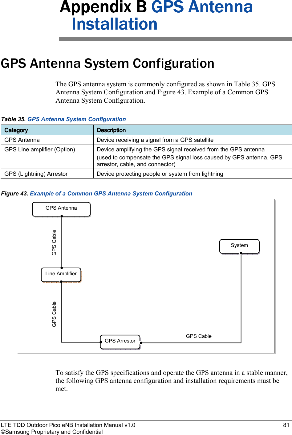
Samsung Electronics Co SLS-BP008Q Outdoor Pico eNB User Manual Manual rev1
Samsung Electronics Co Ltd Outdoor Pico eNB Manual rev1
UserManual.wiki
>
Samsung Electronics Co
>
SLS BP008Q User Manual
User Manual
Navigation menu
Upload a User Manual
Namespaces
Wiki Guide
HTML
PDF
Info
Views
User Manual
Discussion / Help
Navigation


![Error! Use the Home tab to apply 제목 1 to the text that you want to appear here. Error! Use the Home tab to apply 제목 1 to the text that you want to appear here. LTE TDD Outdoor Pico eNB Installation Manual v1.0 3 ©Samsung Proprietary and Confidential System Configuration Outdoor Pico eNB Configuration Figure 1. Outdoor Pico eNB Configuration shows the configuration of Outdoor Pico eNB. Figure 1. Outdoor Pico eNB Configuration Unit: in. (mm) [Bottom View] 12.64 (321) [Top View] 4.66 (118.4) [Right View] [Rear View] [Left View] [Front View] 13.41 (340.5)](https://usermanual.wiki/Samsung-Electronics-Co/SLS-BP008Q/User-Guide-2378976-Page-16.png)
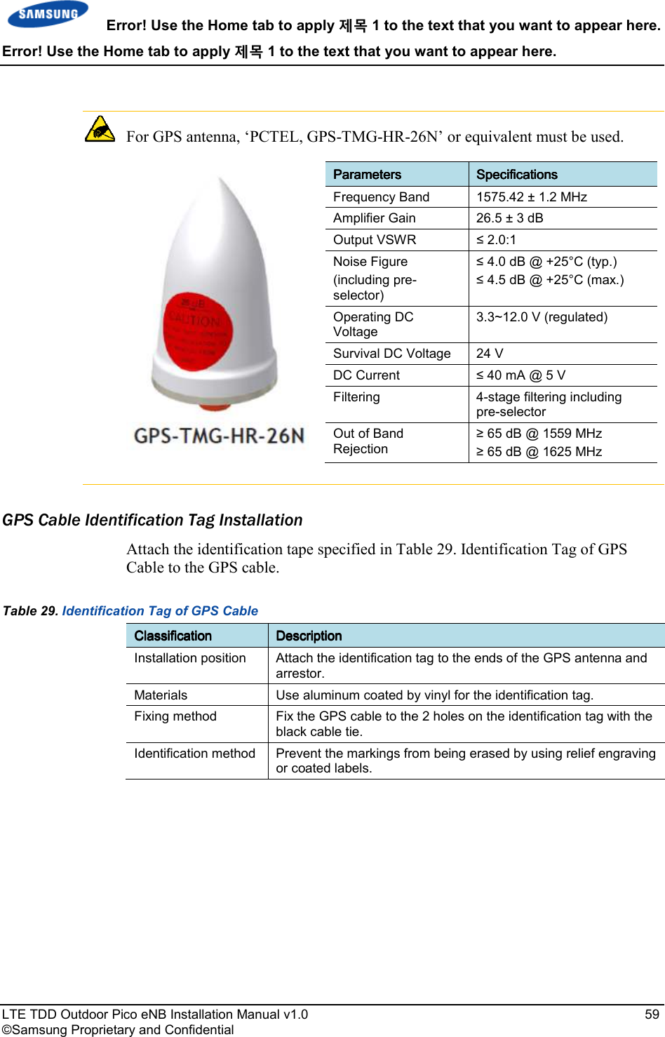
![Error! Use the Home tab to apply 제목 1 to the text that you want to appear here. Error! Use the Home tab to apply 제목 1 to the text that you want to appear here. LTE TDD Outdoor Pico eNB Installation Manual v1.0 5 ©Samsung Proprietary and Confidential Specifications Key Specification Table 1. Key Specification lists the key specifications of the Outdoor Pico eNB. Table 1. Key Specification CategoryCategoryCategoryCategory SpecificationSpecificationSpecificationSpecification Air specification TDD LTE Operating Frequency 2496MHz - 2690MHz Channel Bandwidth 20 MHz Peak Throughput (with Category 3 UE) • 20 MHz BW: DL 78.2 Mbps (2x2 MIMO), UL 19.5 Mbps (1x2 SIMO) • Calculation condition: DL/UL PHY error rate 2 %, configuration 1-3 Tx Power /Carrier • 5 W/Carrier/Path (1 Carrier case) • 3 W/Carrier/Path (2 Carrier case) • 2 W/Carrier/Path (3 Carrier case) Antenna Configuration Max. 3Carriers, 2Tx/2Rx Backhaul Copper GE 2 port Optic GE 1 port Daisy chain Copper FE/GE 1 port Holdover 8 h Power Specification Table 2. Power Specifications lists the power specifications of the Outdoor Pico eNB. Table 2. Power Specifications CategoryCategoryCategoryCategory StandardStandardStandardStandard Rated Voltage 120-240 V AC With tolerance +/- 10% Rated Current Rated current 2 A @ 120 V AC Dimension and Weight Table 3. Dimension and Weight lists the dimensions and weight of the Outdoor Pico eNB. Table 3. Dimension and Weight ItemItemItemItem SpecificationSpecificationSpecificationSpecification Dimension [in. (mm)], W × D × H 12.64 × 4.66 × 13.4 (321 × 118.4 × 340.5)](https://usermanual.wiki/Samsung-Electronics-Co/SLS-BP008Q/User-Guide-2378976-Page-18.png)
![Error! Use the Home tab to apply 제목 1 to the text that you want to appear here. Error! Use the Home tab to apply 제목 1 to the text that you want to appear here. LTE TDD Outdoor Pico eNB Installation Manual v1.0 6 ©Samsung Proprietary and Confidential Weight [lb(kg)] Less than 26.45 lb (12 kg) GPSR Specification Table 4. GPSR Specification lists the specifications of the Outdoor Pico eNB’s GPS receiver (GPSR). Table 4. GPSR Specification ItemItemItemItem SpecificationSpecificationSpecificationSpecification Received Signal from GPS GPS L1 Signal Accuracy/Stability 0.05 ppm Phase Accuracy • ±1 us (lock state) • ±8 us (holdover state) Environmental Condition Table 5. Ambient Specification lists the environmental conditions and related standards such as operational temperature and humidity. Table 5. Ambient Specification CategoryCategoryCategoryCategory RangeRangeRangeRange Temperature Condition (-30) to 55°C (without solar load) (-30) to 50°C (with solar load) Storage Temperature -40~70°C Humidity Condition 0~99 % (relative humidity), not to exceed 30g/m3 absolute humidity Storage Humidity 5~95 % (relative humidity), not to exceed 30g/m3 absolute humidity Altitude (-60)~1,800 m@50°C Earthquake Telcordia GR-63-Core (Zone4) Sound Pressure Level N/A Dust and Waterproof Rating IEC 60529 IP65 Cooling Natural Convection Cooling](https://usermanual.wiki/Samsung-Electronics-Co/SLS-BP008Q/User-Guide-2378976-Page-19.png)
![Error! Use the Home tab to apply 제목 1 to the text that you want to appear here. Error! Use the Home tab to apply 제목 1 to the text that you want to appear here. LTE TDD Outdoor Pico eNB Installation Manual v1.0 12 ©Samsung Proprietary and Confidential Unit: in. (mm) [Front View] 14.78 (375.5) [Top View] 6.32 (160.5) 14.25 (362) Foundation Work System Arrangement Refer to Table 7. Recommended Distances for System for the minimum distances that must be secured around the Outdoor Pico eNB in each direction for its installation and maintenance. Table 7. Recommended Distances for System CategoryCategoryCategoryCategory Recommended DistancesRecommended DistancesRecommended DistancesRecommended Distances Front/Rear 31.5 in. (800 mm) or more Side 7.87 in. (200 mm) or more Top/Bottom 11.8 in. (300 mm) or more Figure 4. Outdoor Pico eNB Arrangement (Wall Type)](https://usermanual.wiki/Samsung-Electronics-Co/SLS-BP008Q/User-Guide-2378976-Page-25.png)
![Error! Use the Home tab to apply 제목 1 to the text that you want to appear here. Error! Use the Home tab to apply 제목 1 to the text that you want to appear here. LTE TDD Outdoor Pico eNB Installation Manual v1.0 13 ©Samsung Proprietary and Confidential Figure 5. Outdoor Pico eNB Arrangement (Pole Type) Pole: Ф2.375 ~4.5 in. (Ф60.3 ~114.3 mm) [Side View] Unit: in. (mm) 14.78 (375.5) 12.56 (319) 6.32 (160.5) 4.8 ~7.24 (122 ~184) Pole: Ф2.375 ~4.5 in. (Ф60.3 ~114.3 mm)](https://usermanual.wiki/Samsung-Electronics-Co/SLS-BP008Q/User-Guide-2378976-Page-26.png)
![Error! Use the Home tab to apply 제목 1 to the text that you want to appear here. Error! Use the Home tab to apply 제목 1 to the text that you want to appear here. LTE TDD Outdoor Pico eNB Installation Manual v1.0 28 ©Samsung Proprietary and Confidential Figure 15. Leveling Using a Level (Wall Type) [Measuring Horizontal Position] [Wall Type] [Measuring Vertical Position] [Measuring Horizontal Position]](https://usermanual.wiki/Samsung-Electronics-Co/SLS-BP008Q/User-Guide-2378976-Page-41.png)
![Error! Use the Home tab to apply 제목 1 to the text that you want to appear here. Error! Use the Home tab to apply 제목 1 to the text that you want to appear here. LTE TDD Outdoor Pico eNB Installation Manual v1.0 29 ©Samsung Proprietary and Confidential Figure 16. Leveling Using a Level (Pole Type) Insulation Test The insulation test information is show in Table 17. Insulation Test. Table 17. Insulation Test ClassificationClassificationClassificationClassification DescriptionDescriptionDescriptionDescription Test Method The insulation tester (Megger) is used for measurement. Position of lead line of insulation tester Wall Type Lead line_A Unit Mounting Bracket Fixing Hex. Bolt Lead line_B Outdoor Pico eNB Fixing Hex Bolt Pole Type Lead line_A M12 Stud Bolt Lead line_B Outdoor Pico eNB Fixing Hex Bolt Evaluation Criteria • Good: 500 V/100 MΩ or more • Poor: Less than 500 V/100 MΩ Corrective Measures for Poor Leveling • Check contact between the system and anchor bolt and re-assemble it. (Note: The anchor bolt must be shielded using an insulator such as an insulation bushing.) • Check the damage of an insulator such as an insulation bushing or Bakelite, and replace it accordingly. [Measuring Vertical Position] [Measuring Horizontal Position] [Pole Type]](https://usermanual.wiki/Samsung-Electronics-Co/SLS-BP008Q/User-Guide-2378976-Page-42.png)
![Error! Use the Home tab to apply 제목 1 to the text that you want to appear here. Error! Use the Home tab to apply 제목 1 to the text that you want to appear here. LTE TDD Outdoor Pico eNB Installation Manual v1.0 31 ©Samsung Proprietary and Confidential Figure 17. Schematic Diagram for Insulation Test (Wall Type) Figure 18. Schematic Diagram for Insulation Test (Pole Type) Unit Mounting Bracket Fixing Hex. Bolt [Megger] [Wall Type] Outdoor Pico eNB Fixing Hex Bolt [Megger] [Pole Type] M12 Stud Bolt Outdoor Pico eNB Fixing Hex Bolt](https://usermanual.wiki/Samsung-Electronics-Co/SLS-BP008Q/User-Guide-2378976-Page-44.png)
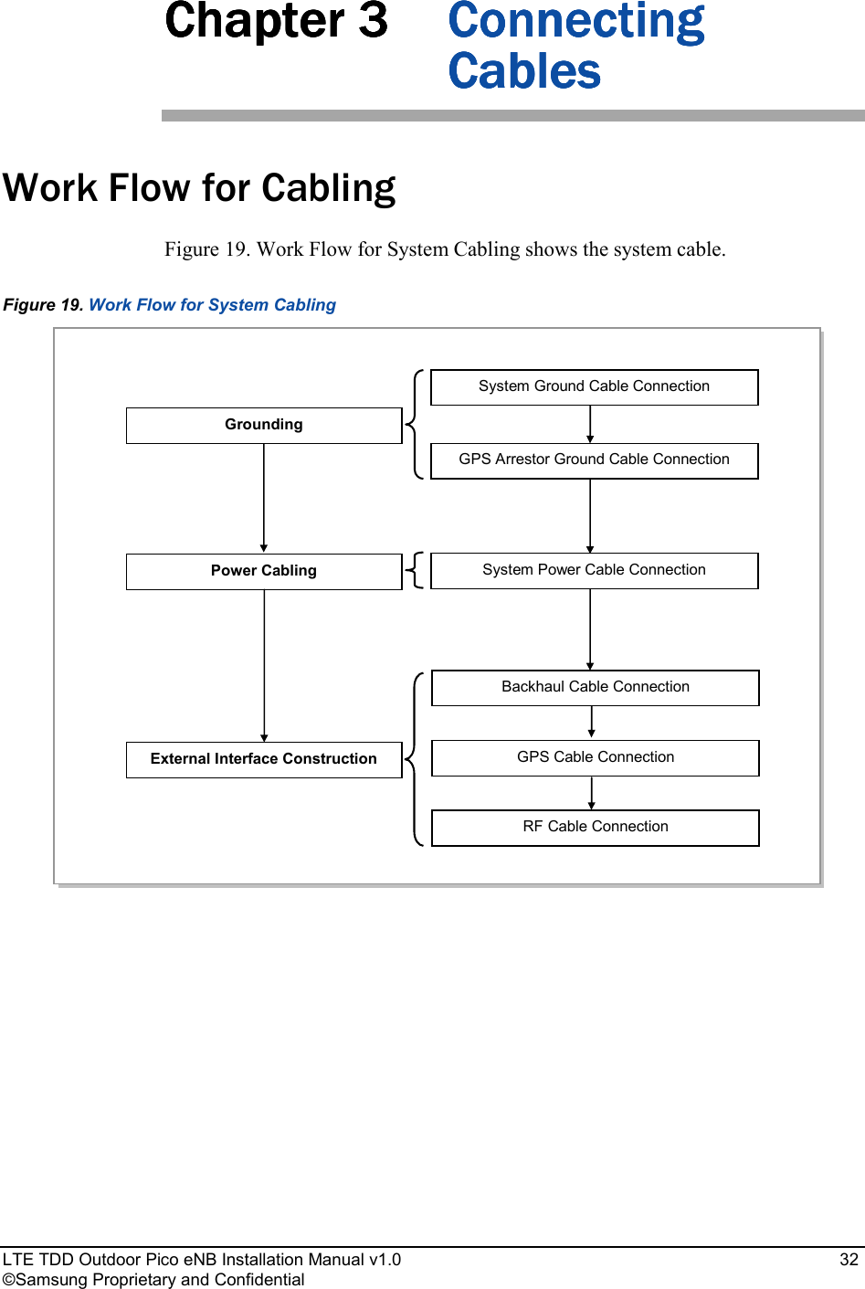
![Error! Use the Home tab to apply 제목 1 to the text that you want to appear here. Error! Use the Home tab to apply 제목 1 to the text that you want to appear here. LTE TDD Outdoor Pico eNB Installation Manual v1.0 37 ©Samsung Proprietary and Confidential Make sure the work is done by personnel properly trained for the job. Cabling Figure 21. Cabling Diagram shows the cabling of the Outdoor Pico eNB. Figure 21. Cabling Diagram 7) RF Cable [AC Distributor] [Ground Bar] [RF Antenna] [SAR, Site Aggregation Router] 3) AC Power Cable 5) Backhaul Ethernet Cable [GPS Antenna] 5) GPS Cable [GPS Arrestor] 4) Backhaul Optic Cable 6) GPS Cable 1) Ground Cable 2) GPS Arrestor Ground Cable 7) RF Cable](https://usermanual.wiki/Samsung-Electronics-Co/SLS-BP008Q/User-Guide-2378976-Page-50.png)
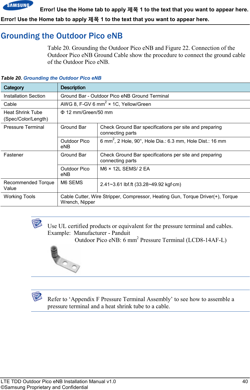
![Error! Use the Home tab to apply 제목 1 to the text that you want to appear here. Error! Use the Home tab to apply 제목 1 to the text that you want to appear here. LTE TDD Outdoor Pico eNB Installation Manual v1.0 41 ©Samsung Proprietary and Confidential Figure 22. Connection of the Outdoor Pico eNB Ground Cable 1) Install the ground cable from the Ground Bar to the Outdoor Pico eNB ground terminal. 2) Assemble a pressure terminal and a heat shrink tube at the end of the Outdoor Pico eNB ground cable. 3) Align the pressure terminal to the mounting hole of the Outdoor Pico eNB ground terminal. 4) Firmly fix the pressure terminal onto the Outdoor Pico eNB ground terminal using fasteners. M6 × 12L SEMS Pressure Terminal Ground Cable Heat Shrink Tube (Green) Ground Bar Ground Cable (AWG 8, F-GV 6 mm2 × 1C) [Outdoor Pico eNB]](https://usermanual.wiki/Samsung-Electronics-Co/SLS-BP008Q/User-Guide-2378976-Page-54.png)

![Error! Use the Home tab to apply 제목 1 to the text that you want to appear here. Error! Use the Home tab to apply 제목 1 to the text that you want to appear here. LTE TDD Outdoor Pico eNB Installation Manual v1.0 46 ©Samsung Proprietary and Confidential Connecting the AC Power Cable Use the following tables and figures to connect the AC power cable to the Outdoor Pico eNB. Table 22. Connecting the AC Power Cable CategoryCategoryCategoryCategory DescriptionDescriptionDescriptionDescription Installation Section AC Distributor - Outdoor Pico eNB Power Input Terminal Cable AWG16 × 3C Connector AC Distributor Check the specification of AC distributor output terminal and prepare fasteners. Outdoor Pico eNB JONHON, DY5T1203SNF, Straight Plug Working Tools Cable Cutter, Wire Stripper, Compressor, Heating Gun, Torque Driver(+), Torque Wrench, Nipper, Soldering Iron, and Lead Table 23. Power Connector Pin Map No.No.No.No. ColorColorColorColor 1 (L) Black 2 (PE) Yellow/green 3 (N) White 3 3 1 1 2 2 [System-side Connector: DY5F1203PNF] [Cable-side Connector: DY5T1203SNF]](https://usermanual.wiki/Samsung-Electronics-Co/SLS-BP008Q/User-Guide-2378976-Page-59.png)
![Error! Use the Home tab to apply 제목 1 to the text that you want to appear here. Error! Use the Home tab to apply 제목 1 to the text that you want to appear here. LTE TDD Outdoor Pico eNB Installation Manual v1.0 48 ©Samsung Proprietary and Confidential Figure 25. Connecting the Outdoor Pico eNB Power Cable (1) Figure 26. Connecting the Outdoor Pico eNB Power Cable (2) AC Distributor (120~240 V AC) 1) Worker shall install a power cable from the AC distributor to the power input port of the Outdoor Pico eNB. 2) Assemble a connector to the end of power cable (Outdoor Pico eNB-side). 3) Connect the power cable assembled with the power connector to the power port of the Outdoor Pico eNB. 4) Turn the connector coupling nut clockwise on the cable and fix it. AC Power Cable (AWG16 × 3C) [Outdoor Pico eNB] Power Connector AC Power Cable Power Input Port (120~240 V AC) Coupling Nut](https://usermanual.wiki/Samsung-Electronics-Co/SLS-BP008Q/User-Guide-2378976-Page-61.png)
![Error! Use the Home tab to apply 제목 1 to the text that you want to appear here. Error! Use the Home tab to apply 제목 1 to the text that you want to appear here. LTE TDD Outdoor Pico eNB Installation Manual v1.0 49 ©Samsung Proprietary and Confidential Backhaul Cable Connection (Optic Type) Follow the steps below to connect the backhaul cable (Optic type) to the Outdoor Pico eNB. Table 24. Backhaul Cable Connection (Optic Type) CategoryCategoryCategoryCategory DescriptionDescriptionDescriptionDescription Installation Section Site Aggregation Router ~ Outdoor Pico eNB_Backhaul (BH_OPT) Port Cable Optic Cable(Single Mode, Outdoor) Connector Site Aggregation Router Checking Site Aggregation Router side connector specifications and preparing connecting parts. Outdoor Pico eNB PDLC, 2LC/UPC[JONHON] Working Tools Optic Cleaner](https://usermanual.wiki/Samsung-Electronics-Co/SLS-BP008Q/User-Guide-2378976-Page-62.png)
![Error! Use the Home tab to apply 제목 1 to the text that you want to appear here. Error! Use the Home tab to apply 제목 1 to the text that you want to appear here. LTE TDD Outdoor Pico eNB Installation Manual v1.0 50 ©Samsung Proprietary and Confidential To prevent foreign substances, outdoor air and moisture from entering the system input/output port and cable inlet (including cable gland and conduit), finish it as follows: - Unused inlet Use the hole finishing materials including waterproof cap and rubber packing. - Cable-installed Port and Cable Inlet After cable installation, block any space in the inlet with tape, compressed sponge, rubber packing, and silicon. Caution for Laser Beam of Optical Module and Cable The optical module and cable used in the system emit bright laser beams. Always handle them with care as there is risk of serious injury if the eyes are exposed to the laser beam of the optical cable. Caution for Optic Cable Connection 1) After removing dust cap of optic cables, use optic cables. 2) Before connecting the optic connector, make sure that the connector is cleaned. If there is any dust or foreign substance when cleaning the connector, do not remove it by blowing with your mouth. Remove the dust or foreign substance by referring to the cleaning instructions in ANNEX E. 3) Don't touch ferrule of optic cables because it is weak. Precautions for connecting the optical cable connector are as follows: - Do not assemble the optical cable while pushing it toward the system. - After putting the cable in a straight line, pull the cable toward the arrow direction slightly with one hand and fix the coupling nut with the other hand. Dust Cap Ferrule [Before removing Dust Cap] [After removing Dust Cap] Cable Shell Coupling Nut](https://usermanual.wiki/Samsung-Electronics-Co/SLS-BP008Q/User-Guide-2378976-Page-63.png)
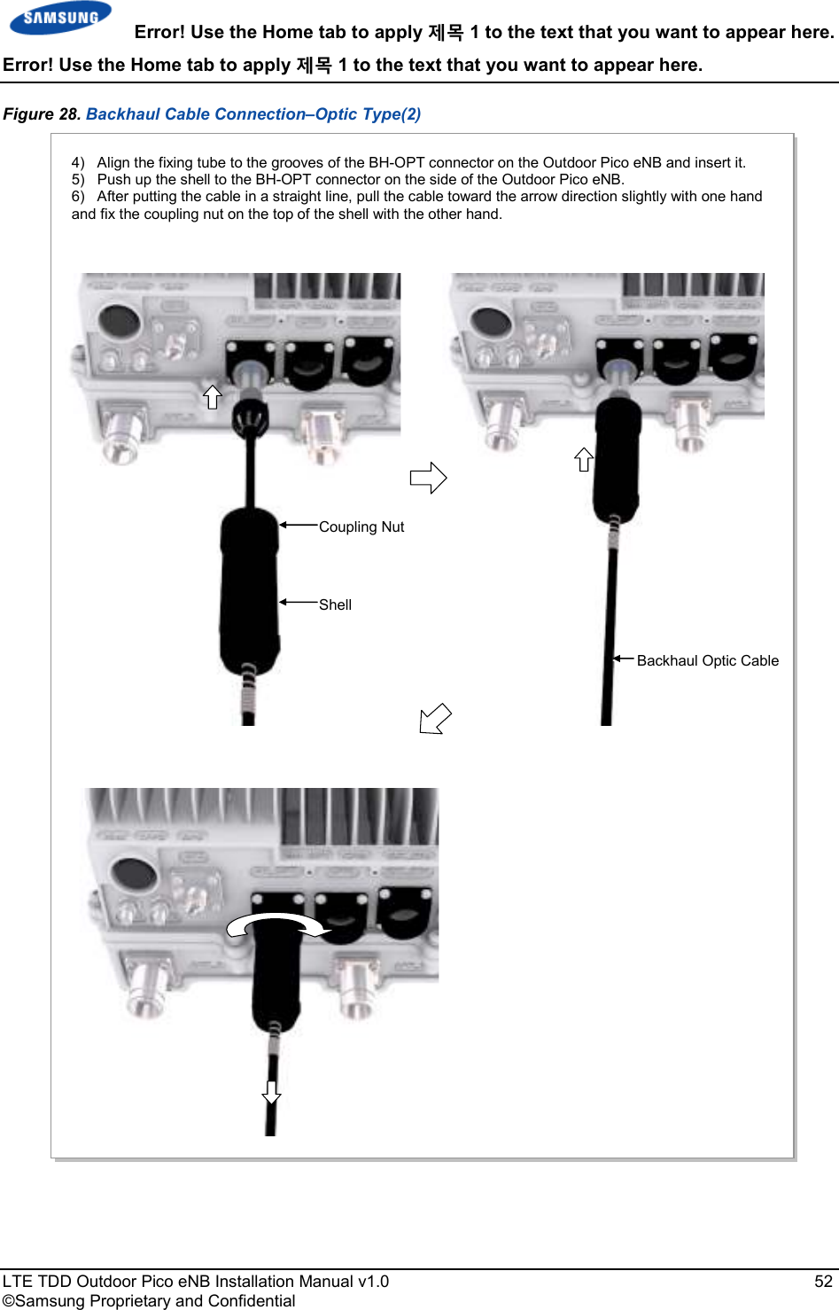
![Error! Use the Home tab to apply 제목 1 to the text that you want to appear here. Error! Use the Home tab to apply 제목 1 to the text that you want to appear here. LTE TDD Outdoor Pico eNB Installation Manual v1.0 51 ©Samsung Proprietary and Confidential Figure 27. Backhaul Cable Connection–Optic Type(1) Site Aggregation Router 1) Install a backhaul cable from the Site Aggregation Router to the backhaul port (BH_OPT) of the Outdoor Pico eNB. 2) Remove the dust cap in the 2LC plug of the backhaul cable. [Outdoor Pico eNB] Backhaul Cable (Optic, Outdoor Type) 3) Connect the 2LC plug on the side of the backhaul cable to the SFP module of the BH-OPT port on the side of the Outdoor Pico eNB. At the time, after inserting the 2LC plug latch upturned, check the ‘click’ sound. Backhaul Cable (Optic) BH-OPT Port 2LC Plug Fixing Tube Latch Latch](https://usermanual.wiki/Samsung-Electronics-Co/SLS-BP008Q/User-Guide-2378976-Page-64.png)
![Error! Use the Home tab to apply 제목 1 to the text that you want to appear here. Error! Use the Home tab to apply 제목 1 to the text that you want to appear here. LTE TDD Outdoor Pico eNB Installation Manual v1.0 55 ©Samsung Proprietary and Confidential Figure 29. Backhaul Cable Connection–Copper Type(1) Site Aggregation Router 1) Install a backhaul cable from the Site Aggregation Router to the backhaul port (BH_ETH) of the Outdoor Pico eNB. 2) Connect the connector of a backhaul cable to the backhaul port (BH_ETH) of the Outdoor Pico eNB. At the time, after inserting the RJ-45 plug latch downturned, check the ‘click’ sound. Backhaul Cable (Copper) [Outdoor Pico eNB] Fixing Tube RJ-45 Plug Latch](https://usermanual.wiki/Samsung-Electronics-Co/SLS-BP008Q/User-Guide-2378976-Page-68.png)
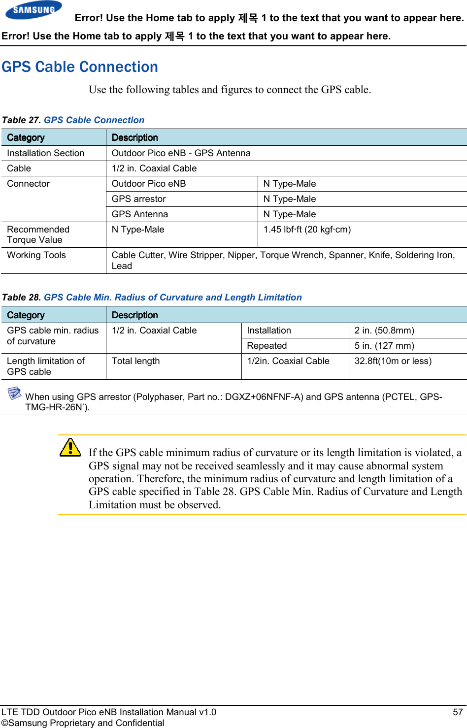

![Error! Use the Home tab to apply 제목 1 to the text that you want to appear here. Error! Use the Home tab to apply 제목 1 to the text that you want to appear here. LTE TDD Outdoor Pico eNB Installation Manual v1.0 60 ©Samsung Proprietary and Confidential GPS Cable Configuration The configuration of GPS cable is shown in Figure 31. GPS Cable Configuration. Figure 31. GPS Cable Configuration 1/2 in. Coaxial Cable (LDF4-50A or equivalent) [GPS Antenna] [Outdoor Pico eNB] [GPS Arrestor] 1/2 in Coaxial cable](https://usermanual.wiki/Samsung-Electronics-Co/SLS-BP008Q/User-Guide-2378976-Page-73.png)
![Error! Use the Home tab to apply 제목 1 to the text that you want to appear here. Error! Use the Home tab to apply 제목 1 to the text that you want to appear here. LTE TDD Outdoor Pico eNB Installation Manual v1.0 61 ©Samsung Proprietary and Confidential Figure 32. GPS Cable Connection (1) [GPS Antenna] 1) Worker shall install a GPS cable (LDF4-50A) from the GPS port of the Outdoor Pico eNB to the GPS antenna. 2) Worker shall assemble the connector to the GPS cable. - Outdoor Pico eNB-side Connector: N Type-Male - GPS Antenna-side Connector: N Type-Male 3) Worker shall connect the N Type-Male connector assembled to the end of the GPS cable to the GPS port of the Outdoor Pico eNB. 1/2 in. Coaxial Cable (LDF4-50A or equivalent) [Outdoor Pico eNB] N Type-Male ConnectorGPS Port[GPS Arrestor] 1/2 in. Coaxial cable GPS Cable (1/2 in. Coaxial Cable)](https://usermanual.wiki/Samsung-Electronics-Co/SLS-BP008Q/User-Guide-2378976-Page-74.png)
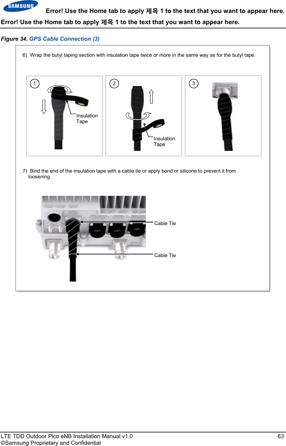
![Error! Use the Home tab to apply 제목 1 to the text that you want to appear here. Error! Use the Home tab to apply 제목 1 to the text that you want to appear here. LTE TDD Outdoor Pico eNB Installation Manual v1.0 64 ©Samsung Proprietary and Confidential Figure 35. GPS Cable Connection (4) 8) Connect the 1/2 in. Coaxial Cable assembled with the N Type-Male connector to the GPS Arrestor port. 9) Connect the N Type-Male connector (assembled to the end of GPS cable) to the GPS antenna port. 1/2 in. Coaxial Cable (LDF4-50A or equivalent) [GPS Antenna] 1/2 in. Coaxial Cable GPS Antenna N Type-Female PortClampHeat Shrink Tube (Jelly Type)Clamp Fixing Screw GPS Antenna Fixing Pipe N Type-Male Connector [GPS Arrestor] 1/2 in. Coaxial cable [Outdoor Pico eNB]](https://usermanual.wiki/Samsung-Electronics-Co/SLS-BP008Q/User-Guide-2378976-Page-77.png)
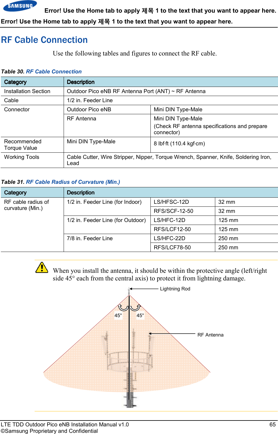
![Error! Use the Home tab to apply 제목 1 to the text that you want to appear here. Error! Use the Home tab to apply 제목 1 to the text that you want to appear here. LTE TDD Outdoor Pico eNB Installation Manual v1.0 70 ©Samsung Proprietary and Confidential RF Cable Connection Use the following figures to connect the cable between the Outdoor Pico eNB and the RF antenna. Figure 36. RF Cable Connection (1) RF Antenna RF Cable (1/2 in. Feeder Line) Mini DIN Type-Male ConnectorRF CableRF Antenna PortHeat Shrink Tube1) Worker shall connect the connectors to the RF ports (Mini DIN Type-Female) at the bottom of the Outdoor Pico eNB. 2) Worker shall assemble the connector at the end of the RF cable. (The specifications of the antenna, supplier-specific connector, and the tightening method are subject to change.) - Outdoor Pico eNB Side Connector: Mini DIN Type-Male - RF Antenna Side Connector: Mini DIN Type-Male 3) Connect the connector which is assembled at the end of the RF cable (Outdoor Pico eNB-side) to the RF antenna port of the Outdoor Pico eNB. [Outdoor Pico eNB]](https://usermanual.wiki/Samsung-Electronics-Co/SLS-BP008Q/User-Guide-2378976-Page-83.png)
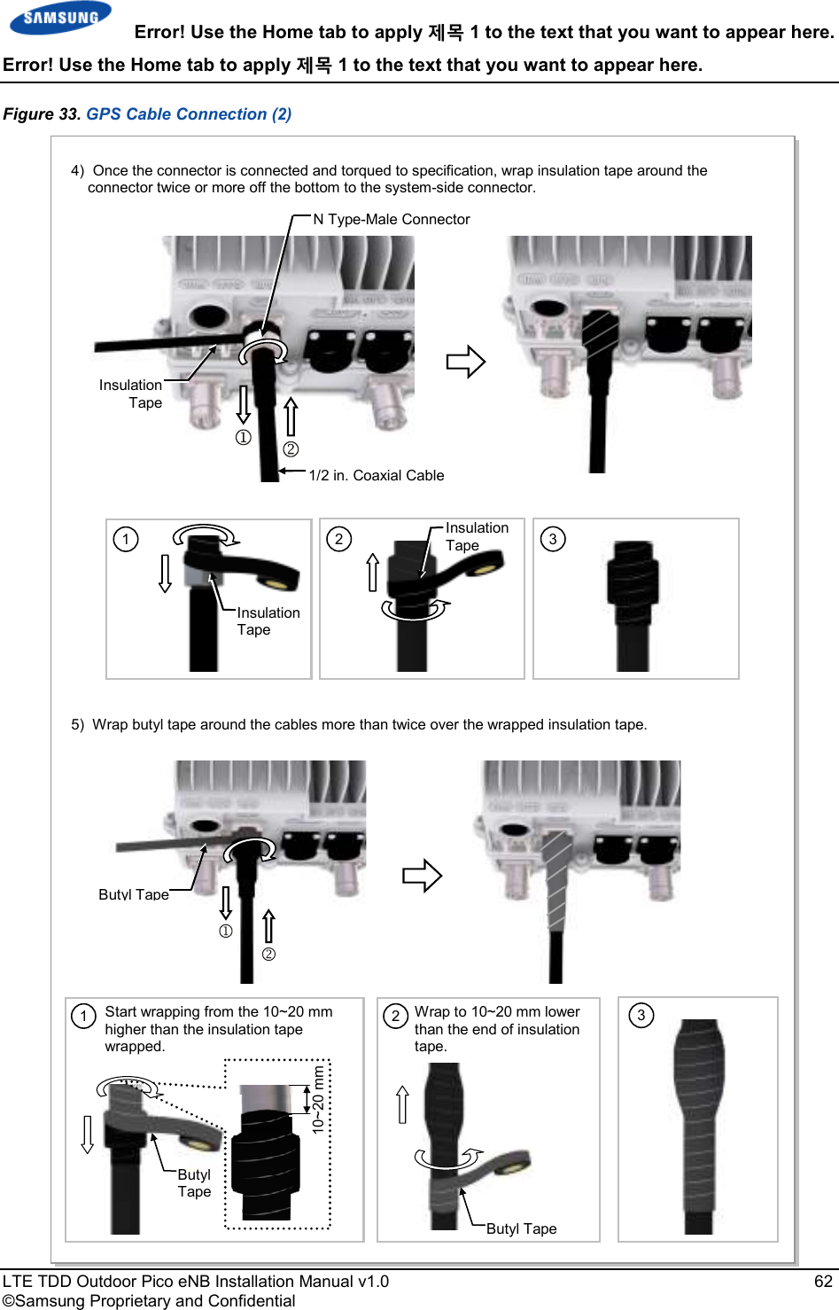
![Error! Use the Home tab to apply 제목 1 to the text that you want to appear here. Error! Use the Home tab to apply 제목 1 to the text that you want to appear here. LTE TDD Outdoor Pico eNB Installation Manual v1.0 71 ©Samsung Proprietary and Confidential Figure 37. RF Cable Connection (2) (1) Start and End points of Butyl Tape Start and End points of Insulation Tape [Mid-point between (1) and (2)] (2) Top side of Connector Nut 4) After connecting a connector, wrap the cable from the system-side connector using insulation tape more than twice so that the metal part of the connector is completely protected, as shown: or install the customer approved boot solution 5) Wrap butyl tape around the cables more than twice over the wrapped insulation tape. Butyl Tape 2 3 Insulation Tape 1 Insulation Tape 2 Butyl Tape 1 Butyl Tape 10~20 mm Start wrapping from 10~20 mm above the insulation tape wrapped. Wrap to 10~20 mm lower than the end of heat shrink tube for the connector nut. Heat Shrink Tube Connector Nut 3 10~20 mm Insulation Tape](https://usermanual.wiki/Samsung-Electronics-Co/SLS-BP008Q/User-Guide-2378976-Page-84.png)
![Error! Use the Home tab to apply 제목 1 to the text that you want to appear here. Error! Use the Home tab to apply 제목 1 to the text that you want to appear here. LTE TDD Outdoor Pico eNB Installation Manual v1.0 73 ©Samsung Proprietary and Confidential Figure 39. RF Cable Connection (4) RF Antenna 8) Connect the connector (assembled to the end of the cable on the RF antenna side) to the RF antenna port. RF Antenna Input Port Heat Shrink Tube (Jelly Type) Mini DIN Type-Male Connector RF Cable 9) After connecting a connector, wrap the cable from the system-side connector using insulation tape more than twice so that the metal part of the connection does not show or install a customer approved weather boot solution. Insulation Tape (1) Starting and Ending points of Butyl Tape Starting and Ending points of Insulation Tape [Mid-point between (1) and (2)] (2) Top side of Connector Nut 2 3 Insulation Tape 1 Insulation Tape](https://usermanual.wiki/Samsung-Electronics-Co/SLS-BP008Q/User-Guide-2378976-Page-86.png)
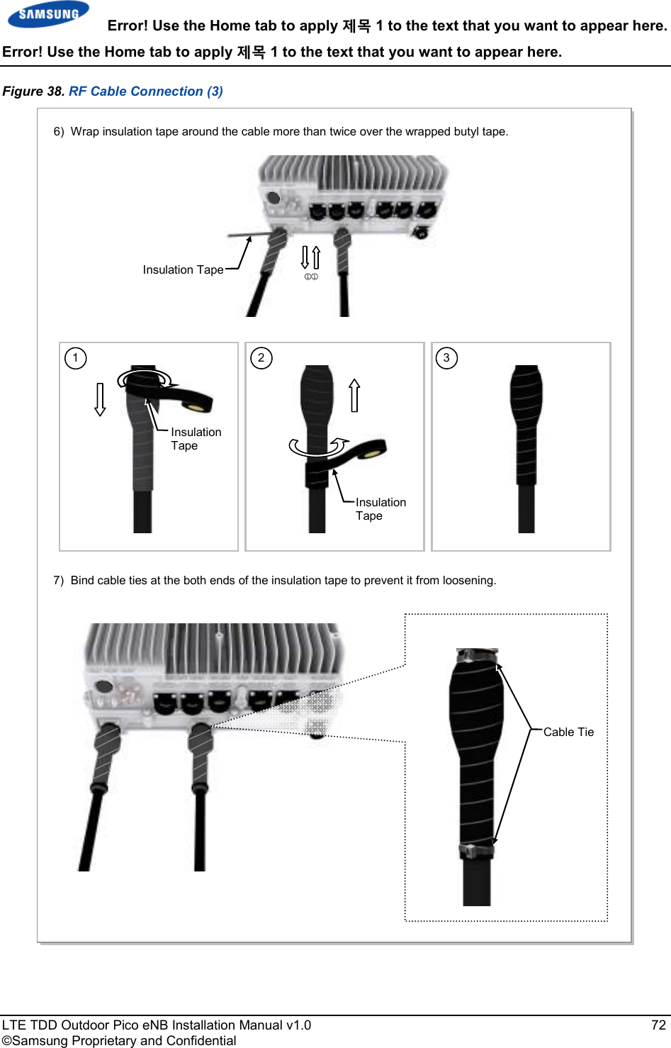
![Error! Use the Home tab to apply 제목 1 to the text that you want to appear here. Error! Use the Home tab to apply 제목 1 to the text that you want to appear here. LTE TDD Outdoor Pico eNB Installation Manual v1.0 74 ©Samsung Proprietary and Confidential Figure 40. RF Cable Connection (5) RF Antenna 8) Connect the connector (assembled to the end of the cable on the RF antenna side) to the RF antenna port. RF Antenna Input Port Heat Shrink Tube (Jelly Type) Mini DIN Type-Male Connector RF Cable 9) After connecting a connector, wrap the cable from the system-side connector using insulation tape more than twice so that the metal part of the connection does not show or install a customer approved weather boot solution. Insulation Tape (1) Starting and Ending points of Butyl Tape Starting and Ending points of Insulation Tape [Mid-point between (1) and (2)] (2) Top side of Connector Nut 2 3 Insulation Tape 1 Insulation Tape Butyl Tape10) Wrap butyl tape around the cables more than twice over the wrapped insulation tape. 11) Wrap insulation tape around the cable more than twice over the wrapped butyl tape. Insulation Tape 2 Butyl Tape 1 Butyl Tape 10~20 mm Start wrapping from the 10~20 mm higher than the insulation tape wrapped. Wrap to 10~20 mm lower than the end of heat shrink tube for the connector nut. 3 Heat shrink tube Connector Nut 10~20 mm 2 3 Insulation Tape 1 Insulation Tape](https://usermanual.wiki/Samsung-Electronics-Co/SLS-BP008Q/User-Guide-2378976-Page-87.png)


![Error! Use the Home tab to apply 제목 8 to the text that you want to appear here. Error! Use the Home tab to apply 제목 8 to the text that you want to appear here. LTE TDD Outdoor Pico eNB Installation Manual v1.0 90 ©Samsung Proprietary and Confidential Wall Figure 46. GPS Antennal Installation (Wall) GPS Antenna Wall Fixing Pipe [Ф 1~1.46 in. (25~37 mm)] GPS Antenna GPS Antenna Wall Fixing Clamp Assembly ≒ Min. 19.68 in. (500 mm)](https://usermanual.wiki/Samsung-Electronics-Co/SLS-BP008Q/User-Guide-2378976-Page-103.png)
![Error! Use the Home tab to apply 제목 8 to the text that you want to appear here. Error! Use the Home tab to apply 제목 8 to the text that you want to appear here. LTE TDD Outdoor Pico eNB Installation Manual v1.0 91 ©Samsung Proprietary and Confidential Floor Figure 47. GPS Antennal Installation (Floor) GPS Antenna Floor Fixing Pipe [Ф 1~1.46 in. (25~37 mm)] GPS Antenna M10 Anchor Bolt Assembly≒ Min. 19.69 in. (500 mm) Concrete Block ≒ Min. 15.74 in. (400 mm) ≒ Min. 9.84 in. (250 mm)](https://usermanual.wiki/Samsung-Electronics-Co/SLS-BP008Q/User-Guide-2378976-Page-104.png)
![Error! Use the Home tab to apply 제목 8 to the text that you want to appear here. Error! Use the Home tab to apply 제목 8 to the text that you want to appear here. LTE TDD Outdoor Pico eNB Installation Manual v1.0 101 ©Samsung Proprietary and Confidential Finishing the Connector Connection Part by Tape Check Items Check the following items in Figure 52. Check Items for Finishing the Connector Connection Part before finishing the connector connection part by tape. Figure 52. Check Items for Finishing the Connector Connection Part * Wrapping only the metal part of connector connection using insulation tape * Wrapping the tape with overlapping Starting and Ending points of Insulation Tape [Mid-point between (1) and (2)] Wrap the tape using half of the tape width so it is overlapped. (For both insulation tape and butyl tape) Tape Width Overlap area of tape (1) Starting and Ending points of Butyl tape (2) Top side of Connector Nut X O](https://usermanual.wiki/Samsung-Electronics-Co/SLS-BP008Q/User-Guide-2378976-Page-114.png)
![Error! Use the Home tab to apply 제목 8 to the text that you want to appear here. Error! Use the Home tab to apply 제목 8 to the text that you want to appear here. LTE TDD Outdoor Pico eNB Installation Manual v1.0 103 ©Samsung Proprietary and Confidential IBCTM Brand Cleaner Method that uses IBCTM Brand Cleaner is as follows: IBCTM Brand type Cleaner (P/N 9393) Method that uses IBCTM Brand Cleaner (P/N 9393) for LC-LC and MU connector is as follows: Figure 53. Optic Connector Cleaner (IBCTM Brand Type Cleaner: P/N 9393) Guide Cap Nozzle Outer Shell Lock Button Lock Button (for Extend Nozzle) Guide Cap Cover Guide Cap Guide Cap [Optic Connector Cleaner Configuration] [Nozzle Extension] [In Case of LC type Connector (Plug)] [In Case of LC type Connector (Jack)]](https://usermanual.wiki/Samsung-Electronics-Co/SLS-BP008Q/User-Guide-2378976-Page-116.png)
![Error! Use the Home tab to apply 제목 8 to the text that you want to appear here. Error! Use the Home tab to apply 제목 8 to the text that you want to appear here. LTE TDD Outdoor Pico eNB Installation Manual v1.0 104 ©Samsung Proprietary and Confidential Figure 54. Optic Module Cleaning (LC type Jack) 1) To clean the optic module, remove the guide cap from the cleaner (P/N: 9393). Guide Cap Nozzle Outer Shell Optic Module Nozzle Outer Shell [IBC Brand Cleaner: P/N 9393] 2) Insert a cleaner guide cap to every ferrule of the optic module. Clean it by pushing the outer shell toward the nozzle until you hear the sound of the detergent being sprayed. (Repeat once or twice.)](https://usermanual.wiki/Samsung-Electronics-Co/SLS-BP008Q/User-Guide-2378976-Page-117.png)
![Error! Use the Home tab to apply 제목 8 to the text that you want to appear here. Error! Use the Home tab to apply 제목 8 to the text that you want to appear here. LTE TDD Outdoor Pico eNB Installation Manual v1.0 105 ©Samsung Proprietary and Confidential Figure 55. Optic Cable Connector Cleaning (LC type plug) 1) To clean the optic cable connector, open the guide cap cover from the cleaner (P/N: 9393) 2) Insert a cleaner guide cap to every ferrule of the optic cable connector. Clean it by pushing the outer shell toward the nozzle until you hear the sound of the detergent being sprayed. (Repeat once or twice.) Guide Cap Nozzle Outer Shell Guide Cap Cover Guide Cap Nozzle Outer Shell LC Type Connector [IBC Brand Cleaner: P/N 9393]](https://usermanual.wiki/Samsung-Electronics-Co/SLS-BP008Q/User-Guide-2378976-Page-118.png)
![Error! Use the Home tab to apply 제목 8 to the text that you want to appear here. Error! Use the Home tab to apply 제목 8 to the text that you want to appear here. LTE TDD Outdoor Pico eNB Installation Manual v1.0 106 ©Samsung Proprietary and Confidential Figure 56. Measuring the Optical Output and Connecting the Optic Connector 1) Check the optical output again using an optic power meter. 2) If the optical output measurement result meets the reference value, clean the connector again and connect it. If the measurement result does not meet the reference value, discard the cable, replace it with a new cable, and then clean the new one and connect it to the system [LC/PC Plug] [Optic Power meter]](https://usermanual.wiki/Samsung-Electronics-Co/SLS-BP008Q/User-Guide-2378976-Page-119.png)
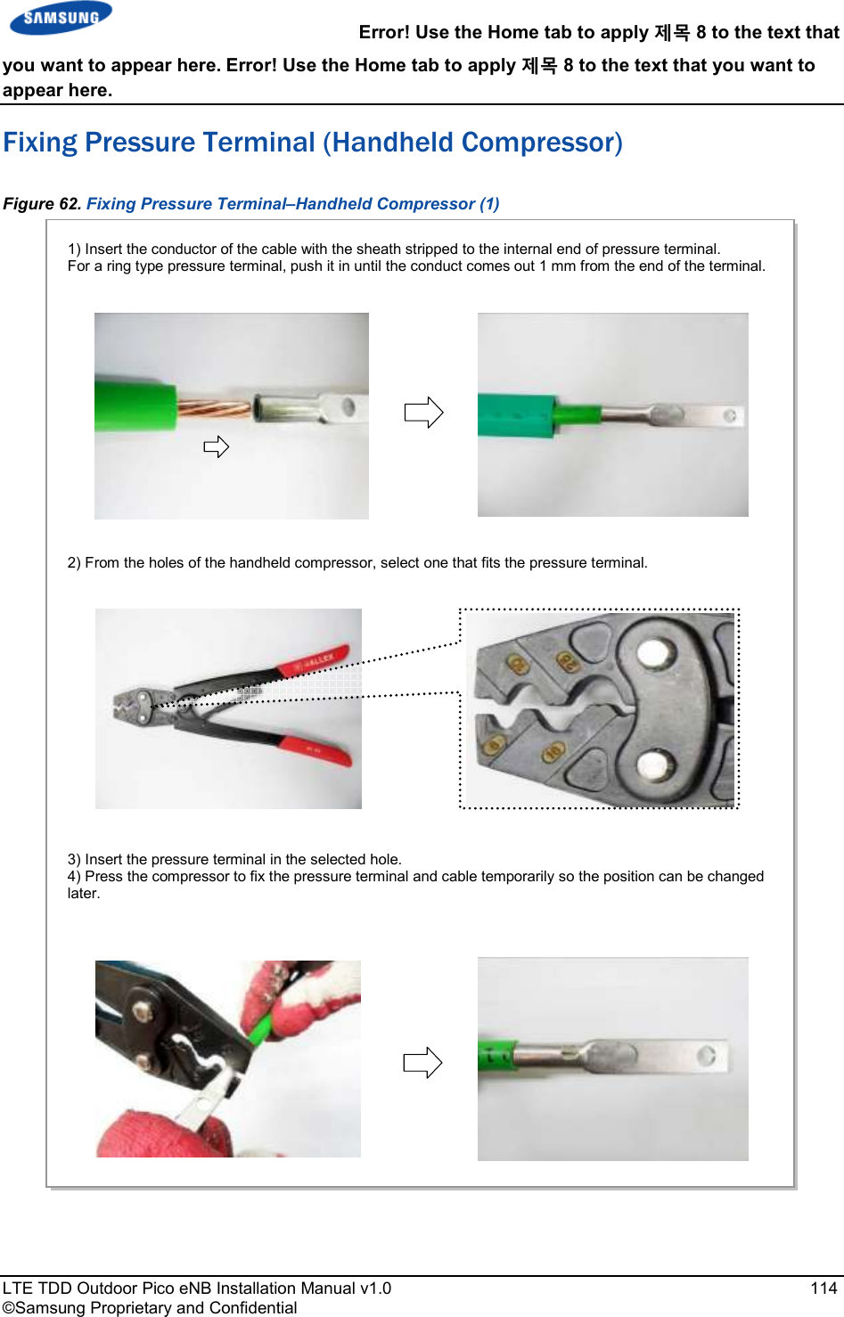
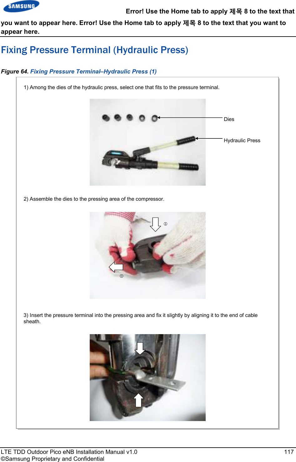
![LTE TDD Outdoor Pico eNB Installation Manual v1.0 107 ©Samsung Proprietary and Confidential Appendix G Appendix G Appendix G Appendix G Pressure Pressure Pressure Pressure Terminal AssemblyTerminal AssemblyTerminal AssemblyTerminal Assembly Preparations To connect a pressure terminal to a cable, prepare the items listed in Figure 57. Preparations. Figure 57. Preparations [Cable Cutter] [Wire Stripper] [Handheld Compressor] [Hydraulic Press] [Heating Gun] [Marking Pen] [Cutter Blade] [Steel Ruler] [Scissors] [Cable] [Pressure Terminal] [Heat Shrink Tube]](https://usermanual.wiki/Samsung-Electronics-Co/SLS-BP008Q/User-Guide-2378976-Page-120.png)
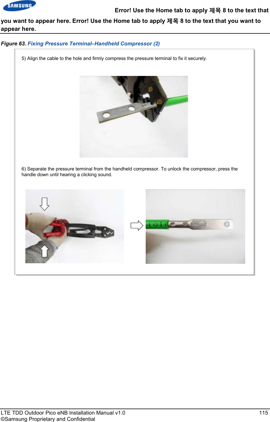
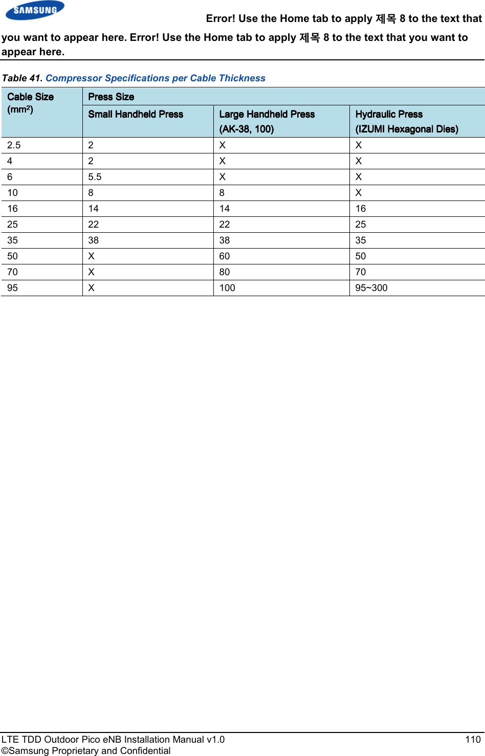
![Error! Use the Home tab to apply 제목 8 to the text that you want to appear here. Error! Use the Home tab to apply 제목 8 to the text that you want to appear here. LTE TDD Outdoor Pico eNB Installation Manual v1.0 108 ©Samsung Proprietary and Confidential Pressure Reference Table Refer to the following tables and figures to assemble a pressure terminal to a cable. Table 40. Pressure Reference Table for Pressure Terminal CategoryCategoryCategoryCategory Copper tube length of a pressure terminalCopper tube length of a pressure terminalCopper tube length of a pressure terminalCopper tube length of a pressure terminal Number ofNumber ofNumber ofNumber of pressure pressure pressure pressure pointspointspointspoints mmmmmmmm In.In.In.In. Hand 11 mm or less 0.43 in. 1 Hand 12~15 mm 0.47~0.59 in. 2 Hand 16~23 mm 0.63~0.91 in. 3 Hand 24~32 mm 0.94~1.26 in. 4 Hand 33 mm or more 1.3 in. or more 5 Hydraulic 30 mm or less 1.18 in. or less 2 Hydraulic 31~47 mm 1.22~1.85 in. 3 Hydraulic 48~63 mm 1.89~2.48 in. 4 Hydraulic 64 mm or more 2.52 in. or more 5 Figure 58. Pressure Reference Drawing (Handheld Compressor) [1-spot] [2-spot] [3-spot] [4-spot] Unit: in. (mm) 0.43 (11) 0.18 (4.5) 0.47 (12) 0.59 (15) 0.63 (16) 0.91 (23) 0.94 in. (24) 1.26 (32) 0.63 (16) 0.18 (4.5) Copper Tube Starting Middle of Copper Tube Arbitrary Fixing Reference Points](https://usermanual.wiki/Samsung-Electronics-Co/SLS-BP008Q/User-Guide-2378976-Page-121.png)
![Error! Use the Home tab to apply 제목 8 to the text that you want to appear here. Error! Use the Home tab to apply 제목 8 to the text that you want to appear here. LTE TDD Outdoor Pico eNB Installation Manual v1.0 109 ©Samsung Proprietary and Confidential Figure 59. Pressure Reference Drawing (Hydraulic Press) Unit: in. (mm) [2-spot] [3-spot] [4-spot] 1.18 (30) [4-spot] Copper Tube Starting Duplicate Pressure Arbitrary Fixing Reference Points 0.53 (13.5) 1.22 (31) 0.53 (13.5) 1.22 (31) 1.85 (47) 1.89 (48) 2.48 (63) 2.52 (64)](https://usermanual.wiki/Samsung-Electronics-Co/SLS-BP008Q/User-Guide-2378976-Page-122.png)
![you want to appear here. Error! Use the Home tab to apply appear here. LTE TDD Outdoor Pico eNB Installation Manual©Samsung Proprietary and Confidential A wire stripper is used differently depending on its manufacturer or type. Therefore, refer to the user manual enclosed with the product. The specifications and cautions Vender: Weidmuller Model: Weidmuller Specifications: For outer diameter 6 - To prevent the cutter blade of conductor, adjust the length of thickness. - Make sure that the cutter blade goes into the cable sheath completely.- Rotate the wire stripper perpendicularly to the cable. Error! Use the Home tab to apply 제목Error! Use the Home tab to apply 제목 8 to the text that you want to Installation Manual v1.0 ©Samsung Proprietary and Confidential A wire stripper is used differently depending on its manufacturer or type. Therefore, refer to the user manual enclosed with the product. The specifications and cautions for the wire stripper described in this manual are: Vender: Weidmuller Model: Weidmuller-AM25 (Order No-9001080000) Specifications: For outer diameter 6-24 mm PVC sheath up to 4.5 mm sheath cutting depth To prevent the cutter blade of the wire stripper from touching the cable conductor, adjust the length of the cutter blade by checking the cable sheath Make sure that the cutter blade goes into the cable sheath completely.Rotate the wire stripper perpendicularly to the cable. [X] [O] 제목 8 to the text that 8 to the text that you want to 113 A wire stripper is used differently depending on its manufacturer or type. wire stripper described in this manual are: wire stripper from touching the cable cutter blade by checking the cable sheath Make sure that the cutter blade goes into the cable sheath completely.](https://usermanual.wiki/Samsung-Electronics-Co/SLS-BP008Q/User-Guide-2378976-Page-126.png)