Samsung Electronics Co SLS-BP008Q Outdoor Pico eNB User Manual Manual rev1
Samsung Electronics Co Ltd Outdoor Pico eNB Manual rev1
User Manual

Radio Access Network
LTE TDD Outdoor Pico eNB
Installation Manual
Describes how to install the Samsung LTE Outdoor Pico eNB including how to
connect cables.
Document Version 1.0
August 2014
Document Number: 2600-00GR31GAA

© 2014 SAMSUNG Electronics Co. Ltd.
All Rights Reserved. No part of this document may be photocopied, reproduced, stored in a retrieval
system, or transmitted, in any form or by any means whether, electronic, mechanical, or otherwise
without the prior written permission of SAMSUNG Electronics Co., Ltd.
No warranty of accuracy is given concerning the contents of the information contained in this
publication. To the extent permitted by law no liability (including liability to any person by reason of
negligence) will be accepted by SAMSUNG Electronics Co., Ltd., its subsidiaries or employees for
any direct or indirect loss or damage caused by omissions from or inaccuracies in this document.
SAMSUNG Electronics Co., Ltd. reserves the right to change details in this publication without
notice.
This manual should be read and used as a guideline for properly installing and/or operating the
product. Owing to product variations across the range, any illustrations and photographs used in
this manual may not be a wholly accurate depiction of the actual products you are using.
This manual may be changed for system improvement, standardization and other technical
reasons without prior notice.
Samsung Networks documentation is available at http://www.samsungdocs.com

LTE TDD Outdoor Pico eNB Installation Manual v1.0 iii
©Samsung Proprietary and Confidential
Contents
ContentsContents
Contents
Preface ix
Relevance ........................................................................................................................................ ix
Conventions in This Document ....................................................................................................... ix
Revision History ................................................................................................................................ x
Organization of This Document ....................................................................................................... x
Related Documentation .................................................................................................................. xi
Personal and Product Safety ........................................................................................................... xii
Chapter 1 Installation Prerequisites 1
Unboxing and Transportation .......................................................................................................... 1
Prerequisites Required for Transport ........................................................................................... 1
OSHA Training .............................................................................................................................. 1
Unboxing Procedure .................................................................................................................... 2
System Configuration ....................................................................................................................... 3
Outdoor Pico eNB Configuration ................................................................................................. 3
External Interface of Outdoor Pico eNB ....................................................................................... 4
Specifications ................................................................................................................................... 5
Key Specification .......................................................................................................................... 5
Power Specification ..................................................................................................................... 5
Dimension and Weight ................................................................................................................ 5
GPSR Specification ....................................................................................................................... 6
Environmental Condition ............................................................................................................. 6
Cautions for Installation ................................................................................................................... 7
Before Installing ........................................................................................................................... 7
While Installing ............................................................................................................................ 7
After Installing ............................................................................................................................. 8
Installation Tools .............................................................................................................................. 9
Chapter 2 System Installation 11
Installation of Outdoor Pico eNB ................................................................................................... 11
Foundation Work ........................................................................................................................... 12
System Arrangement ................................................................................................................. 12
Marking and Drilling .................................................................................................................. 14
Fixing System .................................................................................................................................. 16
Assemble Tightening Parts for Outdoor Pico eNB ..................................................................... 17
Fix the Outdoor Pico eNB (Wall Type) ........................................................................................ 18
Fix the Outdoor Pico eNB (Pole Type) ........................................................................................ 21
Installing GPS arrestor ............................................................................................................... 26
System Leveling .............................................................................................................................. 27
Insulation Test ................................................................................................................................ 29
Chapter 3 Connecting Cables 32
Work Flow for Cabling .................................................................................................................... 32
Cable Path Inspection ................................................................................................................ 34
Cable Cutting ............................................................................................................................. 34
Cable Installation ....................................................................................................................... 34
Cable Binding ............................................................................................................................. 35
Connector Attachment............................................................................................................... 36

Contents
LTE TDD Outdoor Pico eNB Installation Manual v1.0 iv
©Samsung Proprietary and Confidential
Identification Tag Attachment ................................................................................................... 36
Cabling ............................................................................................................................................ 37
Grounding ...................................................................................................................................... 39
Grounding the Outdoor Pico eNB .............................................................................................. 40
Grounding GPS Arrestor ............................................................................................................. 42
Power Cabling ................................................................................................................................ 45
Connecting the AC Power Cable................................................................................................. 46
Backhaul Cable Connection (Optic Type) ................................................................................... 49
External Interface Construction ..................................................................................................... 53
Backhaul Cable Connection (Copper Type) ................................................................................ 53
GPS Cable Connection ................................................................................................................ 57
RF Cable Connection .................................................................................................................. 65
Chapter 4 Checking Installation Status 76
Inspection Plan........................................................................................................................... 77
On-site Inspection and Inspection Checklist ............................................................................... 77
Share Inspection Result and Take Corrective Measures ............................................................ 77
Check the Result of Corrective Action ........................................................................................ 77
Share Corrective Measure Result and Prepare Preventive Plan ................................................ 77
Appendix A Acronyms 80
Appendix B GPS Antenna Installation 81
GPS Antenna System Configuration ............................................................................................... 81
GPS Antenna .............................................................................................................................. 82
Lightening Arrestor .................................................................................................................... 85
Interference Signal ......................................................................................................................... 87
Interference Types ..................................................................................................................... 87
Avoiding Interference ................................................................................................................ 88
GPS Antenna Installation................................................................................................................ 89
Wall ............................................................................................................................................ 90
Floor ........................................................................................................................................... 91
Appendix C Sector Antenna Installation 92
Cautions when Installing a Sector Antenna ................................................................................... 92
Sector Antenna Installation ............................................................................................................ 93
Appendix D Installing Feeder Cable 95
Cautions When Installing Feeder Cable ......................................................................................... 95
Appendix E Connector Assembly 98
RJ-45 (Shield Type) ......................................................................................................................... 98
RJ-45 (Normal Type) ..................................................................................................................... 100
Finishing the Connector Connection Part by Tape ....................................................................... 101
Check Items .............................................................................................................................. 101
Appendix F Cleaning Optic Connector 102
Cleaning Optic Connector ............................................................................................................ 102
IBCTM Brand Cleaner ................................................................................................................... 103
IBCTM Brand type Cleaner (P/N 9393) .................................................................................... 103
Appendix G Pressure Terminal Assembly 107
Preparations ................................................................................................................................. 107
Pressure Reference Table............................................................................................................. 108
Assembling Pressure Terminal ..................................................................................................... 111
Strip the Cable Sheath ............................................................................................................. 111
Fixing Pressure Terminal (Handheld Compressor) ................................................................... 114

Contents
LTE TDD Outdoor Pico eNB Installation Manual v1.0 v
©Samsung Proprietary and Confidential
Fixing Pressure Terminal (Hydraulic Press) .............................................................................. 117
Assembling Heat Shrink Tube .................................................................................................. 120
Appendix H Standard Torque 121

LTE TDD Outdoor Pico eNB Installation Manual v1.0 vi
©Samsung Proprietary and Confidential
List of Figures
Figure 1. Outdoor Pico eNB Configuration ...................................................................................................... 3
Figure 2. External Interface of Outdoor Pico eNB ........................................................................................... 4
Figure 3. Procedure to Install the System ..................................................................................................... 11
Figure 4. Outdoor Pico eNB Arrangement (Wall Type) ................................................................................. 12
Figure 5. Outdoor Pico eNB Arrangement (Pole Type) ................................................................................. 13
Figure 6. System Marking-Wall Type (1) ....................................................................................................... 14
Figure 7. System Marking-Wall Type (2) ....................................................................................................... 15
Figure 8. Assemble Tightening Parts for Installing Outdoor Pico eNB .......................................................... 17
Figure 9. Fix Unit Mounting Bracket (Wall Type) .......................................................................................... 19
Figure 10. Fixing the Outdoor Pico eNB (Wall Type) (1) ................................................................................. 20
Figure 11. Fix Unit-Mounting Bracket and Pole-Mounting Bracket ................................................................ 22
Figure 12. Fix the Outdoor Pico eNB–Pole Type (1) ........................................................................................ 24
Figure 13. Fixing the Outdoor Pico eNB–Pole Type (2) ................................................................................... 25
Figure 14. Installing GPS arrestor (Wall) ......................................................................................................... 26
Figure 15. Leveling Using a Level (Wall Type) ................................................................................................. 28
Figure 16. Leveling Using a Level (Pole Type) ................................................................................................. 29
Figure 17. Schematic Diagram for Insulation Test (Wall Type) ....................................................................... 31
Figure 18. Schematic Diagram for Insulation Test (Pole Type) ....................................................................... 31
Figure 19. Work Flow for System Cabling ....................................................................................................... 32
Figure 20. Detailed Cabling Procedure ............................................................................................................ 33
Figure 21. Cabling Diagram ............................................................................................................................. 37
Figure 22. Connection of the Outdoor Pico eNB Ground Cable ...................................................................... 41
Figure 23. Connecting GPS Arrestor ground cable .......................................................................................... 43
Figure 24. Power Equipment Diagram ............................................................................................................ 45
Figure 25. Connecting the Outdoor Pico eNB Power Cable (1) ....................................................................... 48
Figure 26. Connecting the Outdoor Pico eNB Power Cable (2) ....................................................................... 48
Figure 27. Backhaul Cable Connection–Optic Type(1) .................................................................................... 51
Figure 28. Backhaul Cable Connection–Optic Type(2) .................................................................................... 52
Figure 29. Backhaul Cable Connection–Copper Type(1) ................................................................................. 55
Figure 30. Backhaul Cable Connection–Copper Type(2) ................................................................................. 56
Figure 31. GPS Cable Configuration ................................................................................................................ 60
Figure 32. GPS Cable Connection (1) ............................................................................................................... 61
Figure 33. GPS Cable Connection (2) ............................................................................................................... 62
Figure 34. GPS Cable Connection (3) ............................................................................................................... 63
Figure 35. GPS Cable Connection (4) ............................................................................................................... 64
Figure 36. RF Cable Connection (1) ................................................................................................................. 70
Figure 37. RF Cable Connection (2) ................................................................................................................. 71
Figure 38. RF Cable Connection (3) ................................................................................................................. 72
Figure 39. RF Cable Connection (4) ................................................................................................................. 73
Figure 40. RF Cable Connection (5) ................................................................................................................. 74
Figure 41. RF Cable Connection (6) ................................................................................................................. 75
Figure 42. Installation Checking Procedure .................................................................................................... 76
Figure 43. Example of a Common GPS Antenna System Configuration .......................................................... 81
Figure 44. Elevation Mask and Satellites......................................................................................................... 82
Figure 45. GPS Antenna Installation................................................................................................................ 85
Figure 46. GPS Antennal Installation (Wall) .................................................................................................... 90
Figure 47. GPS Antennal Installation (Floor) ................................................................................................... 91

List of Figures
LTE TDD Outdoor Pico eNB Installation Manual v1.0 vii
©Samsung Proprietary and Confidential
Figure 48. Sector Antenna............................................................................................................................... 94
Figure 49. Assembling the RJ-45 Connector (Shield Type) (1) ........................................................................ 98
Figure 50. Assembling the RJ-45 Connector (Shield Type) (2) ........................................................................ 99
Figure 51. Assembling the RJ-45 Connector (Normal Type) ......................................................................... 100
Figure 52. Check Items for Finishing the Connector Connection Part .......................................................... 101
Figure 53. Optic Connector Cleaner (IBCTM Brand Type Cleaner: P/N 9393) .............................................. 103
Figure 54. Optic Module Cleaning (LC type Jack) .......................................................................................... 104
Figure 55. Optic Cable Connector Cleaning (LC type plug) ........................................................................... 105
Figure 56. Measuring the Optical Output and Connecting the Optic Connector .......................................... 106
Figure 57. Preparations ................................................................................................................................. 107
Figure 58. Pressure Reference Drawing (Handheld Compressor) ................................................................. 108
Figure 59. Pressure Reference Drawing (Hydraulic Press) ............................................................................ 109
Figure 60. Stripping Cable Sheath (1) ............................................................................................................ 111
Figure 61. Stripping Cable Sheath (2) ............................................................................................................ 112
Figure 62. Fixing Pressure Terminal–Handheld Compressor (1) ................................................................... 114
Figure 63. Fixing Pressure Terminal–Handheld Compressor (2) ................................................................... 115
Figure 64. Fixing Pressure Terminal–Hydraulic Press (1) .............................................................................. 117
Figure 65. Fixing Pressure Terminal–Hydraulic Press (2) .............................................................................. 118
Figure 66. Assembling Heat Shrink Tube....................................................................................................... 120

LTE TDD Outdoor Pico eNB Installation Manual v1.0 viii
©Samsung Proprietary and Confidential
List of Tables
Table 1. Key Specification .............................................................................................................................. 5
Table 2. Power Specifications ........................................................................................................................ 5
Table 3. Dimension and Weight ..................................................................................................................... 5
Table 4. GPSR Specification ........................................................................................................................... 6
Table 5. Ambient Specification ...................................................................................................................... 6
Table 6. Basic Installation Tools ..................................................................................................................... 9
Table 7. Recommended Distances for System ............................................................................................. 12
Table 8. Anchor Bolt Drill Bits and Hole Depth ............................................................................................ 15
Table 9. Outdoor Pico eNB Installation Tools and Torque Value ................................................................. 16
Table 10. Tightening Parts for Outdoor Pico eNB .......................................................................................... 16
Table 11. Tightening Parts and Tools for Installing Outdoor Pico eNB .......................................................... 17
Table 12. Unit Mounting Bracket Fixing Parts and Tool (Wall Type) ............................................................. 18
Table 13. Outdoor Pico eNB Fixing Parts and Tools (Wall Type).................................................................... 20
Table 14. Unit/Pole Mounting Bracket Fixing Parts and Tools ...................................................................... 21
Table 15. Outdoor Pico eNB Fixing Parts and Tools (Pole Type) .................................................................... 23
Table 16. Leveling Using a Level .................................................................................................................... 27
Table 17. Insulation Test ................................................................................................................................ 29
Table 18. Minimum Recommended Cable Bend Radius ................................................................................ 35
Table 19. Outdoor Pico eNB Connection Cable ............................................................................................. 38
Table 20. Grounding the Outdoor Pico eNB .................................................................................................. 40
Table 21. Grounding GPS Arrestor ................................................................................................................. 42
Table 22. Connecting the AC Power Cable..................................................................................................... 46
Table 23. Power Connector Pin Map ............................................................................................................. 46
Table 24. Backhaul Cable Connection (Optic Type) ....................................................................................... 49
Table 25. Backhaul Cable Connection (Copper Type) .................................................................................... 53
Table 26. Backhaul Cable (Copper Type)/Connector Pin Map ....................................................................... 53
Table 27. GPS Cable Connection .................................................................................................................... 57
Table 28. GPS Cable Min. Radius of Curvature and Length Limitation .......................................................... 57
Table 29. Identification Tag of GPS Cable ...................................................................................................... 59
Table 30. RF Cable Connection ...................................................................................................................... 65
Table 31. RF Cable Radius of Curvature (Min.) .............................................................................................. 65
Table 32. RF Cable Connection at Antenna Connection Area ........................................................................ 68
Table 33. RF Cable Identification Tag ............................................................................................................. 69
Table 34. Construction Situation Checklist .................................................................................................... 77
Table 35. GPS Antenna System Configuration ............................................................................................... 81
Table 36. Curvature Radius of Feeder Cable for Outdoor ............................................................................. 95
Table 37. Curvature Radius of Feeder Cable for Indoor (Based on LS Feeder Line) ...................................... 96
Table 38. Curvature Radius of LDF4-50A ....................................................................................................... 96
Table 39. Connector Connection Torque Value ............................................................................................. 97
Table 40. Pressure Reference Table for Pressure Terminal ......................................................................... 108
Table 41. Compressor Specifications per Cable Thickness .......................................................................... 110
Table 42. Standard Torque Value for Tightening Bolts ................................................................................ 121
Table 43. Brass Bolts Torque Value.............................................................................................................. 121
LTE TDD Outdoor Pico eNB
Installation Manual
©
Samsung Proprietary and Confidential
Preface
PrefacePreface
Preface
This manual describes how to install
Pico eNB
, LTE eNB
Relevance
This manual applies to the following products/software.
Name
NameName
Name
Pico
Conventions
in
Samsung Networks product
Symbols
Symbol
SymbolSymbol
Symbol
Menu Commands
menu |
command
This i
ndicates that you
name of the menu, and
File Names and Paths
These are indicated by a bold typeface. For example:
Copy
filename.ext
Installation Manual
v1.0
Samsung Proprietary and Confidential
Preface
PrefacePreface
Preface
This manual describes how to install
and connect the
cables to
, LTE eNB
.
This manual applies to the following products/software.
Type
TypeType
Type
Hardware
in
This Document
Samsung Networks product
documentation uses
the following conventions
Description
DescriptionDescription
Description
Indicates a task.
Indicates a shortcut or an alternative method.
Provides additional information.
Provides information or instructions that you should follow to avoid
service failure or damage to equipment.
Provides information or instructions that you should follow to avoid
personal injury or fatality.
Provides antistatic precautions that you should observe.
command
ndicates that you
must select a command on a
menu, where
name of the menu, and
command
is the name of the command on that menu.
File Names and Paths
These are indicated by a bold typeface. For example:
filename.ext
into the /home/folder1/folder2/bin/
folder.
ix
cables to
2.5 GHz Outdoor
the following conventions
.
Provides information or instructions that you should follow to avoid
Provides information or instructions that you should follow to avoid
Provides antistatic precautions that you should observe.
menu, where
menu is the
is the name of the command on that menu.
folder.

Preface
LTE TDD Outdoor Pico eNB Installation Manual v1.0 x
©Samsung Proprietary and Confidential
User Input and Console Screen Output Text
Input and output text is presented in the Courier font. For example,
context <designated epc-context-name>
CLI commands are presented in bold small caps. For example,
Type the RTRV-NE-STS command in the input field.
Revision History
The following table lists all versions of this document.
Version
VersionVersion
Version
Publication Date
Publication DatePublication Date
Publication Date
1.0 August 2014
Organization of This Document
Section
SectionSection
Section
Title
TitleTitle
Title
Description
DescriptionDescription
Description
Chapter 1 Installation Prerequisites This chapter introduces the safety rules that must be
understood for installing the Outdoor Pico eNB and
describes some of the key specifications of the Outdoor Pico
eNB.
Chapter 2 System Installation This chapter describes the procedures to install the Outdoor
Pico eNB.
Chapter 3 Connecting Cables This chapter describes the procedures to connect the cables
to the Outdoor Pico eNB.
Chapter 4 Checking Installation Status This chapter describes the procedures of inspecting
installation status after Outdoor Pico eNB installation and
cabling is completed.
Appendix A Acronyms This appendix describes the acronyms used in this manual.
Appendix B GPS Antenna Installation This appendix describes the GPS antenna configurations
and its installation requirements.
Appendix C Sector Antenna Installation This appendix describes the Sector antenna configurations
and its installation requirements
Appendix D Installing Feeder Cable This appendix describes cautions and allowed radius of
curvature when installing feeder line.
Appendix E Connector Assembly This appendix describes the procedure of assembling the
connector.
Appendix F Cleaning Optic Connector This appendix describes the procedure of Cleaning Optic
Connector.
Appendix G Pressure Terminal Assembly This appendix describes the procedure of assembling the
pressure terminal.
Appendix H Standard Torque This appendix describes the standard torque when
tightening bolts.

Preface
LTE TDD Outdoor Pico eNB Installation Manual v1.0 xi
©Samsung Proprietary and Confidential
Related Documentation
• LTE TDD Outdoor Pico eNB System Description

Preface
LTE TDD Outdoor Pico eNB Installation Manual v1.0 xii
©Samsung Proprietary and Confidential
Personal and Product Safety
This product safety information includes European directives, which you must
follow. If these do not apply in your country, please follow similar directives that
do apply in your country.
Electrical
All structural parts are grounded and all input and outputs have built-in isolation
from the network. All input and output ports that connect to external power
sources are designed to meet relevant national safety requirements.
The product contains hazardous energy levels as defined by UL 60950. Care must
be taken when maintaining this equipment as injury to personnel or damage to the
equipment could result from mistakes. Maintenance should only be carried out by
trained and competent engineers who are familiar with the relevant procedures and
instructions.
Lasers
The product is fitted with optic modules rated as Class 1 radiation-emitting devices
under IEC 60825-1.
Manual Handling
Care should be taken when handling equipment. Give due consideration to the
weight of the equipment, the physical capability of the individual(s) handling the
equipment, and movements such as twisting, bending and stooping, which could
lead to skeletal and muscular injuries.
Installation
Installation must be carried out by trained and competent engineers only. All
relevant safety measures must be taken to ensure equipment is not connected to
live power and transmission sources during installation. Equipment must be
correctly installed in order to meet the relevant safety standards and approval
conditions.
The cable between the power distribution point and the installed equipment must
have a cross-sectional area of 1.5 mm
2
.
Maintenance
Maintenance must only be carried out by a suitably trained and competent
technician. All safety instructions must be carefully observed at all times.
Equipment covers should not be removed while live power and transmission is
connected unless in a controlled environment by trained technicians.
Preface
LTE TDD Outdoor Pico eNB Installation Manual v1.0 xiii
©Samsung Proprietary and Confidential
Environment
The product must be operated in an environment within the specified relative
humidity and ambient temperature ranges.
Grounding
To comply with UL 60950, the equipment must be connected to a safety
grounding point via a permanent connection. Grounding points are located on the
product for this purpose. Always connect the ground cable before fitting other
cables. The product must remain grounded continuously unless all connections to
the power supply and data network are all removed.
If equipment is grounded through a cabinet or rack, make sure it is done so
properly according to the installation instructions.
Chemical Warning
This product contains chemicals known to the State of California to cause cancer
and reproductive toxicity.
Double pole /Neutral fusing
Disconnect ac power, before servicing.

LTE TDD Outdoor Pico eNB
Installation Manual
©
Samsung Proprietary and Confidential
Chapter 1
Chapter 1Chapter 1
Chapter 1
Unboxing and Transportation
The following instructions will guide you through how
cabinets and other components to the installation location.
Prerequisite
s Required for Transport
Follow these guidelines when transporting:
•
Before moving the system, check the storage site and remove obstacles in
advance.
• Carry bo
ards in packing boxes and unpack them when installing or mounting.
•
Tighten the system so that it remains secure. Note that the vibration level
should be in the range from 1 to 500 Hz.
•
Use a lift or cart to prevent accidents. However, if the system is being
by people then make sure that there are enough people to carry it safely.
•
While moving the system, boards and other devices should not be damaged by
physical shock, dust, moisture, and static electricity.
OSHA Training
It is important that ALL W
SUPERVISING THIS STA installation manual is validated as qualified by
their G.C. employers as having sufficient training and adequate proficiency
in installing and maintaining MMBS and battery systems, and that they are
awar
e, understand, and abide by all requirements as defined in this manual
and the Field Site Audit Review systems checklist.
OSHA stands for the Occupational Safety and Health Administration, an
agency o
OSHA’s responsibility is
OSHA website:
Installation Manual
v1.0
Samsung Proprietary and Confidential
Chapter 1
Chapter 1Chapter 1
Chapter 1
Installation
InstallationInstallation
Installation
P
PP
P
rerequisite
rerequisitererequisite
rerequisite
Unboxing and Transportation
The following instructions will guide you through how
to unpack and transport
cabinets and other components to the installation location.
s Required for Transport
Follow these guidelines when transporting:
Before moving the system, check the storage site and remove obstacles in
ards in packing boxes and unpack them when installing or mounting.
Tighten the system so that it remains secure. Note that the vibration level
should be in the range from 1 to 500 Hz.
Use a lift or cart to prevent accidents. However, if the system is being
by people then make sure that there are enough people to carry it safely.
While moving the system, boards and other devices should not be damaged by
physical shock, dust, moisture, and static electricity.
It is important that ALL W
ORKERS AND LEADS PERFORMING AND
SUPERVISING THIS STA installation manual is validated as qualified by
their G.C. employers as having sufficient training and adequate proficiency
in installing and maintaining MMBS and battery systems, and that they are
e, understand, and abide by all requirements as defined in this manual
and the Field Site Audit Review systems checklist.
OSHA stands for the Occupational Safety and Health Administration, an
agency o
f the U.S. Department of Labor
OSHA’s responsibility is
worker safety and health protection
OSHA website:
http://www.osha.gov
1
Installation
InstallationInstallation
Installation
rerequisite
rerequisitererequisite
rerequisite
s
ss
s
to unpack and transport
Before moving the system, check the storage site and remove obstacles in
ards in packing boxes and unpack them when installing or mounting.
Tighten the system so that it remains secure. Note that the vibration level
Use a lift or cart to prevent accidents. However, if the system is being
carried
by people then make sure that there are enough people to carry it safely.
While moving the system, boards and other devices should not be damaged by
ORKERS AND LEADS PERFORMING AND
SUPERVISING THIS STA installation manual is validated as qualified by
their G.C. employers as having sufficient training and adequate proficiency
in installing and maintaining MMBS and battery systems, and that they are
e, understand, and abide by all requirements as defined in this manual
OSHA stands for the Occupational Safety and Health Administration, an
worker safety and health protection

Error! Use the Home tab to apply 제목 1 to the text that you want to appear here.
Error! Use the Home tab to apply 제목 1 to the text that you want to appear here.
LTE TDD Outdoor Pico eNB Installation Manual v1.0 2
©Samsung Proprietary and Confidential
Unboxing Procedure
Follow these guidelines when unboxing items:
• The items should remain boxed until they reach the installation site.
• The items are classified in accordance with each job specification and stored at
a location that does not interfere with the working area.
• Unboxed systems should be installed immediately. If not installed
immediately, temporarily store the systems at the installation site.
• Unbox the inner packaging after each system is placed on its installation
location.
• Do not recycle packaging waste. Dispose it in accordance with waste
management laws.
Error! Use the Home tab to apply 제목 1 to the text that you want to appear here.
Error! Use the Home tab to apply 제목 1 to the text that you want to appear here.
LTE TDD Outdoor Pico eNB Installation Manual v1.0 3
©Samsung Proprietary and Confidential
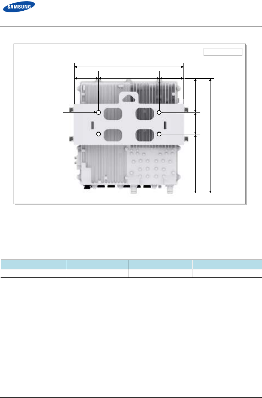
System Configuration
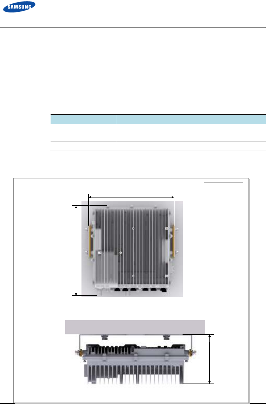
Outdoor Pico eNB Configuration
Figure 1. Outdoor Pico eNB Configuration shows the configuration of Outdoor
Pico eNB.
Figure 1. Outdoor Pico eNB Configuration
Unit: in. (mm)
[Bottom View]
12.64 (321)
[Top View]
4.66 (118.4)
[Right View] [Rear View] [Left View] [Front View]
13.41 (340.5)
Error! Use the Home tab to apply 제목 1 to the text that you want to appear here.
Error! Use the Home tab to apply 제목 1 to the text that you want to appear here.
LTE TDD Outdoor Pico eNB Installation Manual v1.0 4
©Samsung Proprietary and Confidential
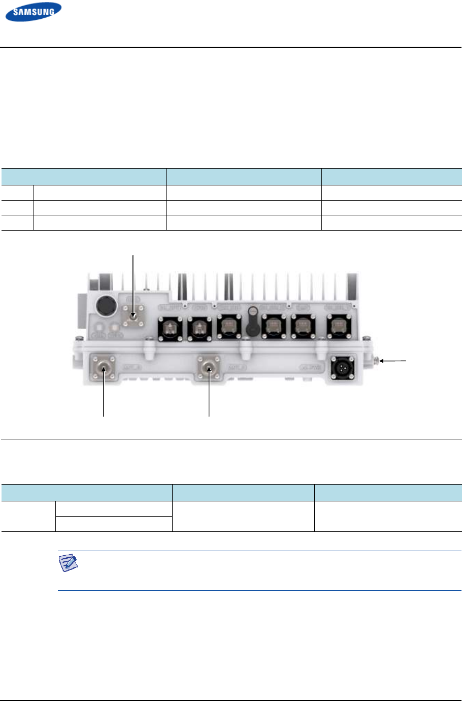
External Interface of Outdoor Pico eNB
Figure 2. External Interface of Outdoor Pico eNB shows the external interface
structure of Outdoor Pico eNB.
Figure 2. External Interface of Outdoor Pico eNB
GPS
BH_OPT
BH_ETH_1
ANT_0
BH_ETH_0
CPRI
LMT
EXT_ETH
ANT_1
Ground
Terminal
10MHz
SYNC
AC_PWR
Error! Use the Home tab to apply 제목 1 to the text that you want to appear here.
Error! Use the Home tab to apply 제목 1 to the text that you want to appear here.
LTE TDD Outdoor Pico eNB Installation Manual v1.0 5
©Samsung Proprietary and Confidential
Specifications
Key Specification
Table 1. Key Specification lists the key specifications of the Outdoor Pico eNB.
Table 1. Key Specification
Category
CategoryCategory
Category
Specification
SpecificationSpecification
Specification
Air specification TDD LTE
Operating Frequency 2496MHz - 2690MHz
Channel Bandwidth 20 MHz
Peak Throughput
(with Category 3 UE)
• 20 MHz BW: DL 78.2 Mbps (2x2 MIMO), UL 19.5 Mbps
(1x2 SIMO)
• Calculation condition: DL/UL PHY error rate 2 %,
configuration 1-3
Tx Power /Carrier • 5 W/Carrier/Path (1 Carrier case)
• 3 W/Carrier/Path (2 Carrier case)
• 2 W/Carrier/Path (3 Carrier case)
Antenna Configuration Max. 3Carriers, 2Tx/2Rx
Backhaul Copper GE 2 port
Optic GE 1 port
Daisy chain Copper FE/GE 1 port
Holdover 8 h
Power Specification
Table 2. Power Specifications lists the power specifications of the Outdoor Pico
eNB.
Table 2. Power Specifications
Category
CategoryCategory
Category
Standard
StandardStandard
Standard
Rated Voltage 120-240 V AC
With tolerance +/- 10%
Rated Current Rated current 2 A @ 120 V AC
Dimension and Weight
Table 3. Dimension and Weight lists the dimensions and weight of the Outdoor
Pico eNB.
Table 3. Dimension and Weight
Item
ItemItem
Item
Specification
SpecificationSpecification
Specification
Dimension [in. (mm)], W × D × H 12.64 × 4.66 × 13.4 (321 × 118.4 × 340.5)
Error! Use the Home tab to apply 제목 1 to the text that you want to appear here.
Error! Use the Home tab to apply 제목 1 to the text that you want to appear here.
LTE TDD Outdoor Pico eNB Installation Manual v1.0 6
©Samsung Proprietary and Confidential
Weight [lb(kg)] Less than 26.45 lb (12 kg)
GPSR Specification
Table 4. GPSR Specification lists the specifications of the Outdoor Pico eNB’s
GPS receiver (GPSR).
Table 4. GPSR Specification
Item
ItemItem
Item
Specification
SpecificationSpecification
Specification
Received Signal from GPS GPS L1 Signal
Accuracy/Stability 0.05 ppm
Phase Accuracy • ±1 us (lock state)
• ±8 us (holdover state)
Environmental Condition
Table 5. Ambient Specification lists the environmental conditions and related
standards such as operational temperature and humidity.
Table 5. Ambient Specification
Category
CategoryCategory
Category
Range
RangeRange
Range
Temperature Condition (-30) to 55°C (without solar load)
(-30) to 50°C (with solar load)
Storage Temperature -40~70°C
Humidity Condition 0~99 % (relative humidity), not to exceed 30g/m
3
absolute
humidity
Storage Humidity 5~95 % (relative humidity), not to exceed 30g/m
3
absolute
humidity
Altitude (-60)~1,800 m@50°C
Earthquake Telcordia GR-63-Core (Zone4)
Sound Pressure Level N/A
Dust and Waterproof
Rating
IEC 60529 IP65
Cooling Natural Convection Cooling

Error! Use the Home tab to apply 제목 1 to the text that you want to appear here.
Error! Use the Home tab to apply 제목 1 to the text that you want to appear here.
LTE TDD Outdoor Pico eNB Installation Manual v1.0 7
©Samsung Proprietary and Confidential
Cautions for Installation
Observe the following safety instructions while installing the Outdoor Pico eNB.
Before Installing
• Post warning signs in areas where high voltage cables are installed.
• Post ‘off limit’ signs in areas where accidents are most expected.
• With guardrails or fences, block open areas such as connecting parts, roof, and
scaffold.
When you install this equipment in the field, it should be installed in a Restricted
Access Location.
While Installing
• The system power must be cut off before installing.
• Be careful that boards mounted on the system and the cables among the boards
are not damaged or scratched when the system is transported or installed.
Make sure the power switch of power supply is off when installing the system.
Installing the system with power switch on may cause system damage or fatal
human injury when cables are not correctly connected.
Wear protection gloves and goggles to prevent damage from debris while drilling
holes in a wall or ceiling.
Do not wear accessories such as watches and rings in order to prevent electrical
shock.
Cover the unused ports (conduit, cable gland, and so on) with a waterproof cap
(sealing cap) to prevent infiltration of foreign material such as dust, moisture, or
insects.
Error! Use the Home tab to apply 제목 1 to the text that you want to appear here.
Error! Use the Home tab to apply 제목 1 to the text that you want to appear here.
LTE TDD Outdoor Pico eNB Installation Manual v1.0 8
©Samsung Proprietary and Confidential
Do not use a base station antenna within a distance of 100 cm from people; also
do not co-locate nor operate in conjunction with any other antenna or transmitter in
order to protect the general public from exposure to radio frequency
electromagnetic field.
To prevent foreign substances, outdoor air, and moisture from entering the system
input/output port and cable inlet (including cable gland and conduit), finish them
as follows:
- Unused Inlet:
Use the hole finishing materials, including waterproof cap and rubber packing.
- Cable-installed Port and Cable Inlet
After installing the cable, block any space in the inlet with tape, compressed
sponge, rubber packing, and silicon.
You must not work alone in any key process.
The outdoor fastening materials, such as stud bolts, hex nuts, spring washers, and
plain washers, must be made of stainless steel (STS 304). Otherwise, it may cause
corrosion and rust to fixing materials.
After Installing
• Cover the cable holes drilled on the floor with a solid cover.
• Remove any debris produced during work and clean up the installation site.
In the system, the laser beam light runs through the optical cable. Handle the
optical cables with care as the laser beam can seriously damage your eyes.
Do not damage installed cables while cleaning the system.
While cleaning the power supply device, take caution that the device does not
come in contact with foreign objects that may cause power failure.
Error
! Use the Home tab to apply
Error! Use the Home tab to apply
LTE TDD Outdoor Pico eNB
Installation Manual
©Samsung Proprietary and Confidential
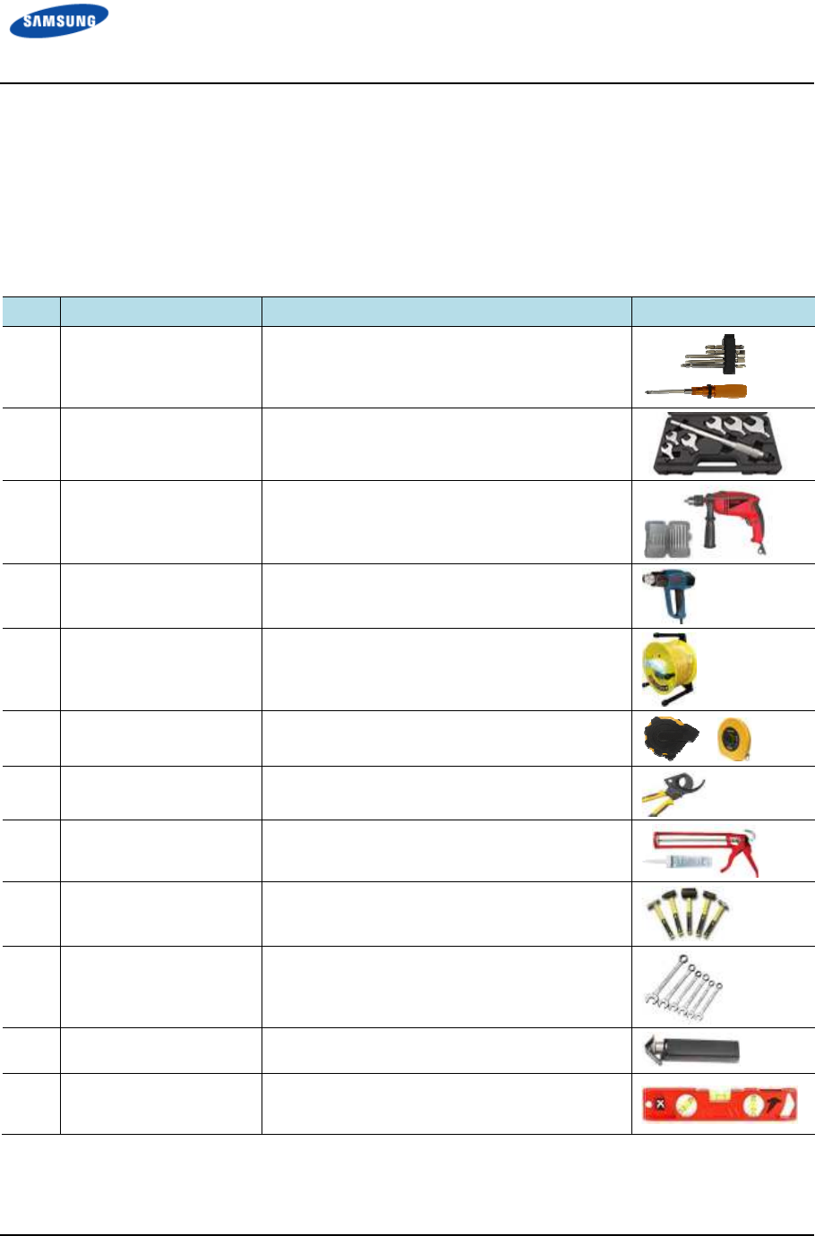
Installation Tools
The basic tools for installation are listed in
additional tools required for each site need to
site survey before starting installation.
Table 6. Basic Installation Tools
No.
No.No.
No.
Name
NameName
Name
1 Torque Driver Set
2 Torque Wrench Set
3 Drill/Bit Set
4 Heating Gun
5 Power Extension Cable
6 Tape Measure
7 Cable Cutter
8 Silicon Gun/Silicon
9 Hammer Set
10 Spanner
11 Wire Stripper
12 Level
! Use the Home tab to apply
제목
1 to the text that you want to appear here.
Error! Use the Home tab to apply
제목
1 to the text that you want to appear here.
Installation Manual
v1.0
©Samsung Proprietary and Confidential
Installation Tools
The basic tools for installation are listed in
Table 6.
Basic Installation Tools
additional tools required for each site need to
be
identified and prepared during a
site survey before starting installation.
Specification
SpecificationSpecification
Specification
Remarks
RemarksRemarks
Remarks
No.0~+No.3 (M2.6~M6 ‘+’ Driver)
0.07~4.34 lbf·ft (1.0~60 kgf·cm)
M6~M12
0.72~2.17 lbfft (10~30 kgfcm), 7.23~36.15 lbfft
(100~500 kgfcm), Replaceable head
0.24~0.67 in. (6~17 mm)
122~572°F (50~300°C)
98.42 ft. (30 m)
16.4 ft./164 ft. (5 m/50 m)
0.24~1.26 in. (6~32 mm)
Normal/Grey and Colorless
Still/Rubber/PVC
0.75 in., 0.94 in., 1.42 in.
(19 mm, 24 mm, 36 mm)
0.24~0.94 in. (6~24 mm)
Normal
1 to the text that you want to appear here.
1 to the text that you want to appear here.
9
Basic Installation Tools
. Any
identified and prepared during a
Remarks
RemarksRemarks
Remarks
Error! Use the Home tab to apply
Error! Use the Home tab to apply
LTE TDD Outdoor Pico eNB
Installation Manual
©Samsung Proprietary and Confidential
13 Megger
The required installation tools may vary depending on the conditions at the site.
In addition to the basic tools, a protractor, compass, GPS receiver, ladder, safety
equipment, cleaning tools
the site
conditions.
Error! Use the Home tab to apply
제목
1 to the text that you want to appear here.
Error! Use the Home tab to apply
제목
1 to the text that you want to appear here.
Installation Manual
v1.0
©Samsung Proprietary and Confidential
+/- 0.08 %, 40 M Ohms
The required installation tools may vary depending on the conditions at the site.
In addition to the basic tools, a protractor, compass, GPS receiver, ladder, safety
equipment, cleaning tools
, and so on
should also be prepared in consideration of
conditions.
1 to the text that you want to appear here.
1 to the text that you want to appear here.
10
The required installation tools may vary depending on the conditions at the site.
In addition to the basic tools, a protractor, compass, GPS receiver, ladder, safety
should also be prepared in consideration of
LTE TDD Outdoor Pico eNB Installation Manual v1.0 11
©Samsung Proprietary and Confidential
Chapter 2
Chapter 2Chapter 2
Chapter 2 System
SystemSystem
System
Installation
InstallationInstallation
Installation
Installation of Outdoor Pico eNB
The procedure to install the Outdoor Pico eNB is shown in Figure 3. Procedure to
Install the System.
Figure 3. Procedure to Install the System
Foundation Work
Unpacking and Transporting
Marking and Drilling
System Arrangement
Fixing System
System Leveling
Insulation Test
Unpacking Items
Importing Items
Pole Type Fixing
Wall Type Fixing
Error! Use the Home tab to apply 제목 1 to the text that you want to appear here.
Error! Use the Home tab to apply 제목 1 to the text that you want to appear here.
LTE TDD Outdoor Pico eNB Installation Manual v1.0 12
©Samsung Proprietary and Confidential
Unit: in. (mm)
[Front View]
14.78 (375.5)
[Top View]
6.32 (160.5)
14.25 (362)
Foundation Work
System Arrangement
Refer to Table 7. Recommended Distances for System for the minimum distances
that must be secured around the Outdoor Pico eNB in each direction for its
installation and maintenance.
Table 7. Recommended Distances for System
Category
CategoryCategory
Category
Recommended Distances
Recommended DistancesRecommended Distances
Recommended Distances
Front/Rear 31.5 in. (800 mm) or more
Side 7.87 in. (200 mm) or more
Top/Bottom 11.8 in. (300 mm) or more
Figure 4. Outdoor Pico eNB Arrangement (Wall Type)
Error! Use the Home tab to apply 제목 1 to the text that you want to appear here.
Error! Use the Home tab to apply 제목 1 to the text that you want to appear here.
LTE TDD Outdoor Pico eNB Installation Manual v1.0 13
©Samsung Proprietary and Confidential
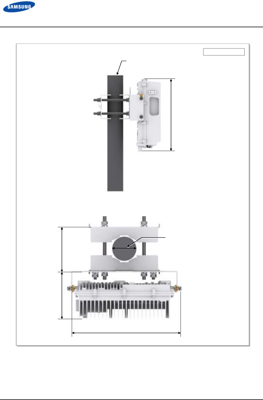
Figure 5. Outdoor Pico eNB Arrangement (Pole Type)
Pole: Ф2.375 ~4.5 in. (Ф60.3 ~114.3 mm)
[Side View]
Unit: in. (mm)
14.78 (375.5)
12.56 (319)
6.32 (160.5)
4.8 ~7.24
(122 ~184)
Pole: Ф2.375 ~4.5 in.
(Ф60.3 ~114.3 mm)
Error! Use the Home tab to apply 제목 1 to the text that you want to appear here.
Error! Use the Home tab to apply 제목 1 to the text that you want to appear here.
LTE TDD Outdoor Pico eNB Installation Manual v1.0 14
©Samsung Proprietary and Confidential
Marking and Drilling
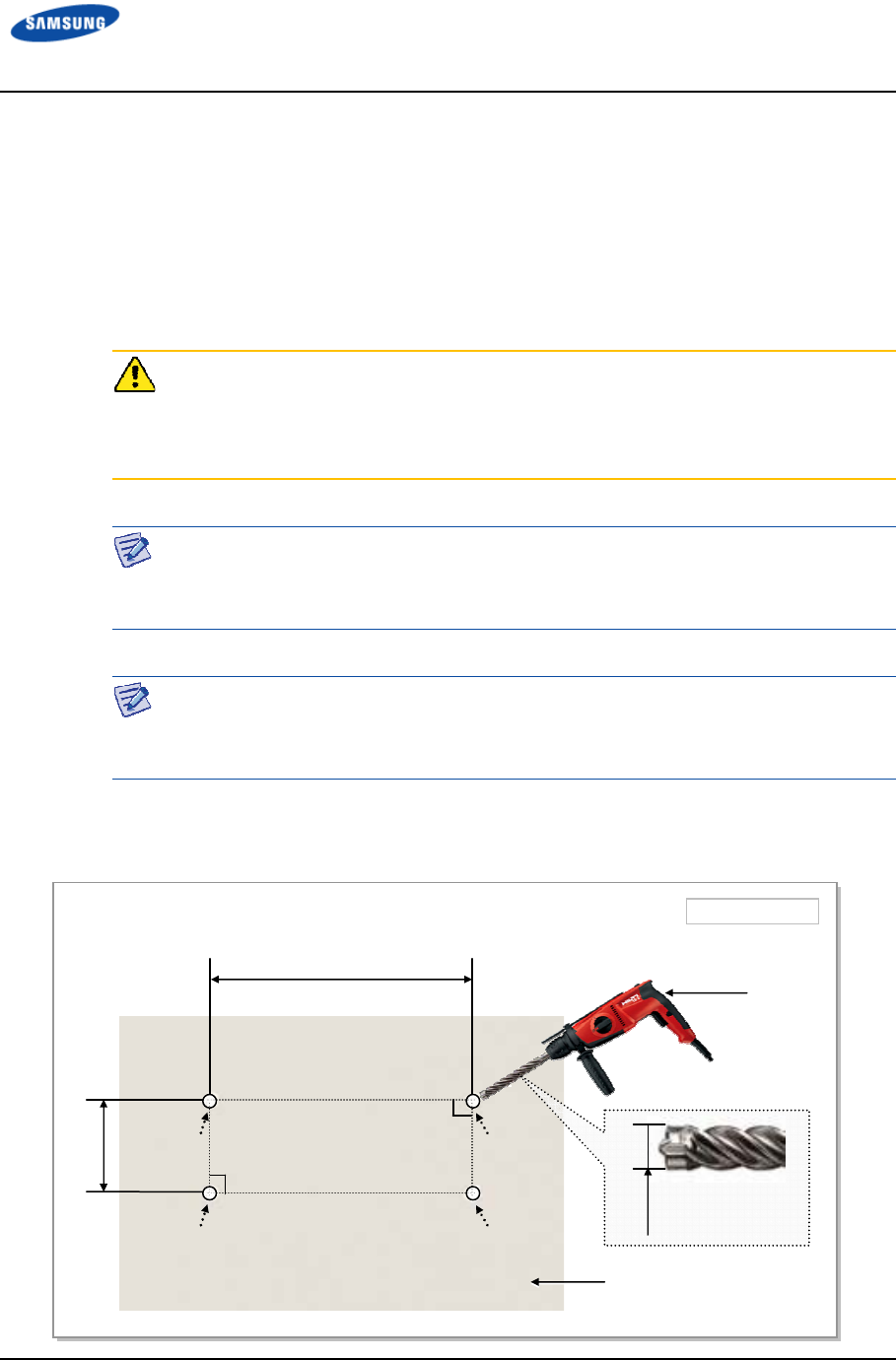
Marking
Before placing the system, mark the position where the system will be installed
using an ink line or a pen. Also mark the positions where anchor bolts will be
fixed.
As a limited range of tuning is allowed for leveling after the system is mounted on
a wall, perform the leveling test (refer to ‘System Leveling’) to check if positions
are marked to be horizontal or vertical before drilling. If the result shows they are
not horizontal or vertical, then modify the marking positions.
Before starting work, check the fixing method for the Outdoor Pico eNB because
the marking and drilling positions and specifications may differ as per the fixing
method.
When position of the system is determined, place the system on the position. Using
a pen, mark the positions where anchor bolts will be fixed in order to reduce
marking error range.
Figure 6. System Marking-Wall Type (1)
Unit: mm
Wall
2.76 (70)
Drill
0.67 (17)
90
°
7.80 (198)
90
°
Error! Use the Home tab to apply 제목 1 to the text that you want to appear here.
Error! Use the Home tab to apply 제목 1 to the text that you want to appear here.
LTE TDD Outdoor Pico eNB Installation Manual v1.0 15
©Samsung Proprietary and Confidential
Anchor Bolt Hole
Ф 0.55 (14)
7.80 (198)
2.76 (70)
Unit: in. (mm)
14.25 (362)
14.78 (375.5)
4.45 (113) 7.58 (192.5)
3.23 (82) 3.23 (82)
Figure 7. System Marking-Wall Type (2)
Drilling
When marking is completed, drill holes for anchor bolts.
Table 8. Anchor Bolt Drill Bits and Hole Depth
Category
CategoryCategory
Category
Anchor Bolt
Anchor BoltAnchor Bolt
Anchor Bolt
Drill Bits
Drill BitsDrill Bits
Drill Bits
Hole Depth
Hole DepthHole Depth
Hole Depth
Wall Type M12 0.67 in. (17 mm) 2.17 in. (55 mm)
Error! Use the Home tab to apply 제목 1 to the text that you want to appear here.
Error! Use the Home tab to apply 제목 1 to the text that you want to appear here.
LTE TDD Outdoor Pico eNB Installation Manual v1.0 16
©Samsung Proprietary and Confidential
Fixing System
Table 9. Outdoor Pico eNB Installation Tools and Torque Value and Table 10.
Tightening Parts for Outdoor Pico eNB list the installation tools and assembly
torque required to install and maintain the Outdoor Pico eNB.
Table 9. Outdoor Pico eNB Installation Tools and Torque Value
Category
CategoryCategory
Category
Installation Tools
Installation ToolsInstallation Tools
Installation Tools
Torque Value
Torque ValueTorque Value
Torque Value
A M6 SEMS Driver (+): M6 1.45 lbfft (20 kgfcm)
B N Type Hexagon: 19 mm 0.87 lbfft (12.0 kgfcm)
C Mini DIN Type Hexagon: 22 mm 8 lbfft (110.4 kgfcm)
Table 10. Tightening Parts for Outdoor Pico eNB
Category
CategoryCategory
Category
Installation Tools
Installation ToolsInstallation Tools
Installation Tools
Torque Value
Torque ValueTorque Value
Torque Value
M8 Hex Bolt Hexagon: 13 mm 8.82 lbfft (122.0 kgfcm)
Hex Nut
The outdoor fastening materials such as stud bolts, hex nuts, spring washers, and
plain washers must be made of stainless steel (STS 304).
‘B’
‘A’
‘C’
‘C’
Error! Use the Home tab to apply 제목 1 to the text that you want to appear here.
Error! Use the Home tab to apply 제목 1 to the text that you want to appear here.
LTE TDD Outdoor Pico eNB Installation Manual v1.0 17
©Samsung Proprietary and Confidential
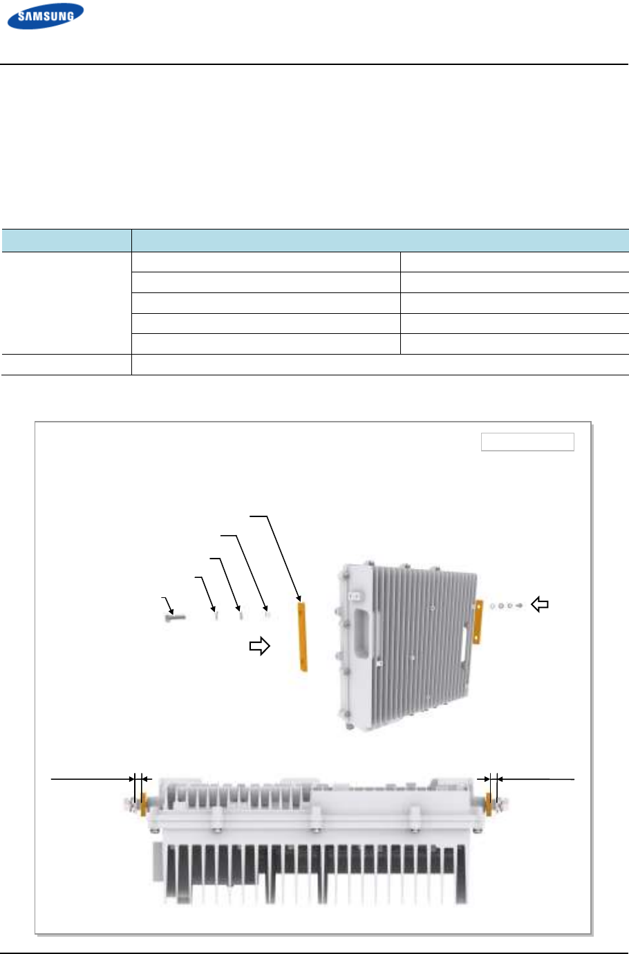
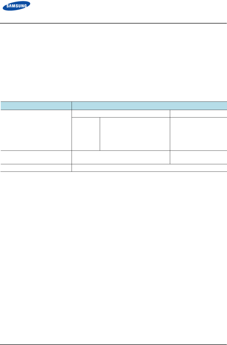
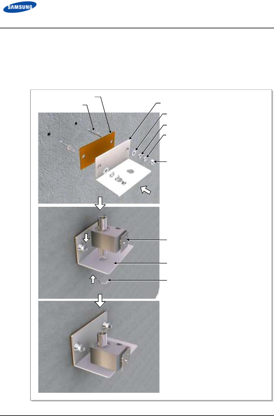
Assemble Tightening Parts for Outdoor Pico eNB
Figure 8. Assemble Tightening Parts for Installing Outdoor Pico eNB illustrates
how to assemble the tightening parts to the fixing holes at the top of left/right sides
to install the Outdoor Pico eNB to the mounting bracket using the items listed in
Table 11. Tightening Parts and Tools for Installing Outdoor Pico eNB.
Table 11. Tightening Parts and Tools for Installing Outdoor Pico eNB
Category
CategoryCategory
Category
Description
DescriptionDescription
Description
Fastener M8 × 30L Hex. Bolt 2 EA
M8 Spring Washer 2 EA
M8 Plain Washer 2 EA
M8 Insulation Bushing 2 EA
Bakelite (5T) 2 EA
Working Tools Torque Wrench (Hexagon: 13 mm), Spanner, Steel Ruler
Figure 8. Assemble Tightening Parts for Installing Outdoor Pico eNB
Tighten the fasteners to the second fixing hole on the left and right sides of the top of Outdoor Pico eNB,
leaving about 0.24 in. (6 mm) clearance.
M8 × 30L Hex. Bolt
M8 Spring Washer
M8 Plain Washer
M8 Insulation Bushing
Unit: in. (mm)
0.24 in. (6 mm)
Bakelite
0.24 in. (6 mm)
Error! Use the Home tab to apply 제목 1 to the text that you want to appear here.
Error! Use the Home tab to apply 제목 1 to the text that you want to appear here.
LTE TDD Outdoor Pico eNB Installation Manual v1.0 18
©Samsung Proprietary and Confidential
Fix the Outdoor Pico eNB (Wall Type)
The procedure for fixing the Outdoor Pico eNB on the wall is as follows:
Fix Unit Mounting Bracket
Use Table 12. Unit Mounting Bracket Fixing Parts and Tool (Wall Type) and
Figure 9. Fix Unit Mounting Bracket (Wall Type) to fix the unit mounting bracket.
Unit Mounting Bracket Fixing Parts and Tool (Wall Type)
Table 12. Unit Mounting Bracket Fixing Parts and Tool (Wall Type)
Category
CategoryCategory
Category
Description
DescriptionDescription
Description
Parts Unit Mounting Bracket 1 EA
Fastener M12 Strong Anchor Assembly
• M12 Strong Anchor
• M12 Spring Washer
• M12 Plain Washer
• M12 Hex. Bolt
4 set
1 EA/set
1 EA/set
1 EA/set
1 EA/set
Recommended Torque Value M12 Hex. Bolt 21.11~31.67 lbfft
(292.0~438.0 kgfcm)
Working Tools Drill, Hammer, Torque Wrench (Hexagon: 19 mm), Level
Error! Use the Home tab to apply 제목 1 to the text that you want to appear here.
Error! Use the Home tab to apply 제목 1 to the text that you want to appear here.
LTE TDD Outdoor Pico eNB Installation Manual v1.0 19
©Samsung Proprietary and Confidential
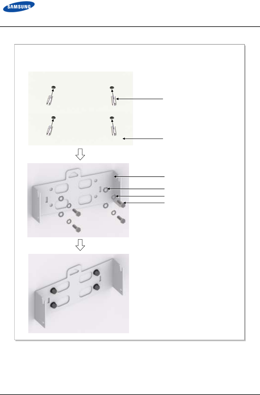
Figure 9. Fix Unit Mounting Bracket (Wall Type)
1) Fix the M12 strong anchors to the holes marked and drilled on the wall.
2) Firmly fix the anchor bolts and unit mounting bracket using the fasteners.
Unit Mounting Bracket
M12 Plain Washer
M12 Spring Washer
M12 Hex. Bolt
M12 Strong Anchor
Wall
Error! Use the Home tab to apply 제목 1 to the text that you want to appear here.
Error! Use the Home tab to apply 제목 1 to the text that you want to appear here.
LTE TDD Outdoor Pico eNB Installation Manual v1.0 20
©Samsung Proprietary and Confidential
Fix the Outdoor Pico eNB
Table 13. Outdoor Pico eNB Fixing Parts and Tools (Wall Type) lists the Outdoor
Pico eNB unit mounting bracket parts.
Table 13. Outdoor Pico eNB Fixing Parts and Tools (Wall Type)
Category
CategoryCategory
Category
Description
DescriptionDescription
Description
Parts M8 × 30L Hex Bolt 4 EA
M8 Spring Washer 4 EA
M8 Plain Washer 4 EA
M8 Insulation Bushing 4 EA
Recommended Torque Value M8 Hex Bolt 8.82 lbfft (122 kgfcm)
Working Tools Torque Wrench (Hexagon: 13 mm), Spanner
Figure 10. Fixing the Outdoor Pico eNB (Wall Type) (1)
1) Hang M8 hex. bolts, which are installed in the second fixing holes on left/right sides of Outdoor Pico
eNB, can on the groove at the top of the unit mounting bracket. At this point, the plain washer and
spring washer should be located outside of the unit mounting bracket.
2) Fix the product securely by tightening fasteners on the remaining holes of the unit mounting bracket.
3) Tighten completely and securely the M8 hex. bolts attached to the second fixing holes on the top of the
Outdoor Pico eNB
.
Top groove of Unit
Mounting Bracket
M8 × 30L Hex. Bolt
Bakelite
Unit Mounting Bracket
M8 Plain Washer
M8 Spring Washer
M8 × 30L Hex. Bolt
M8 Insulation Bushing
Error! Use the Home tab to apply 제목 1 to the text that you want to appear here.
Error! Use the Home tab to apply 제목 1 to the text that you want to appear here.
LTE TDD Outdoor Pico eNB Installation Manual v1.0 21
©Samsung Proprietary and Confidential
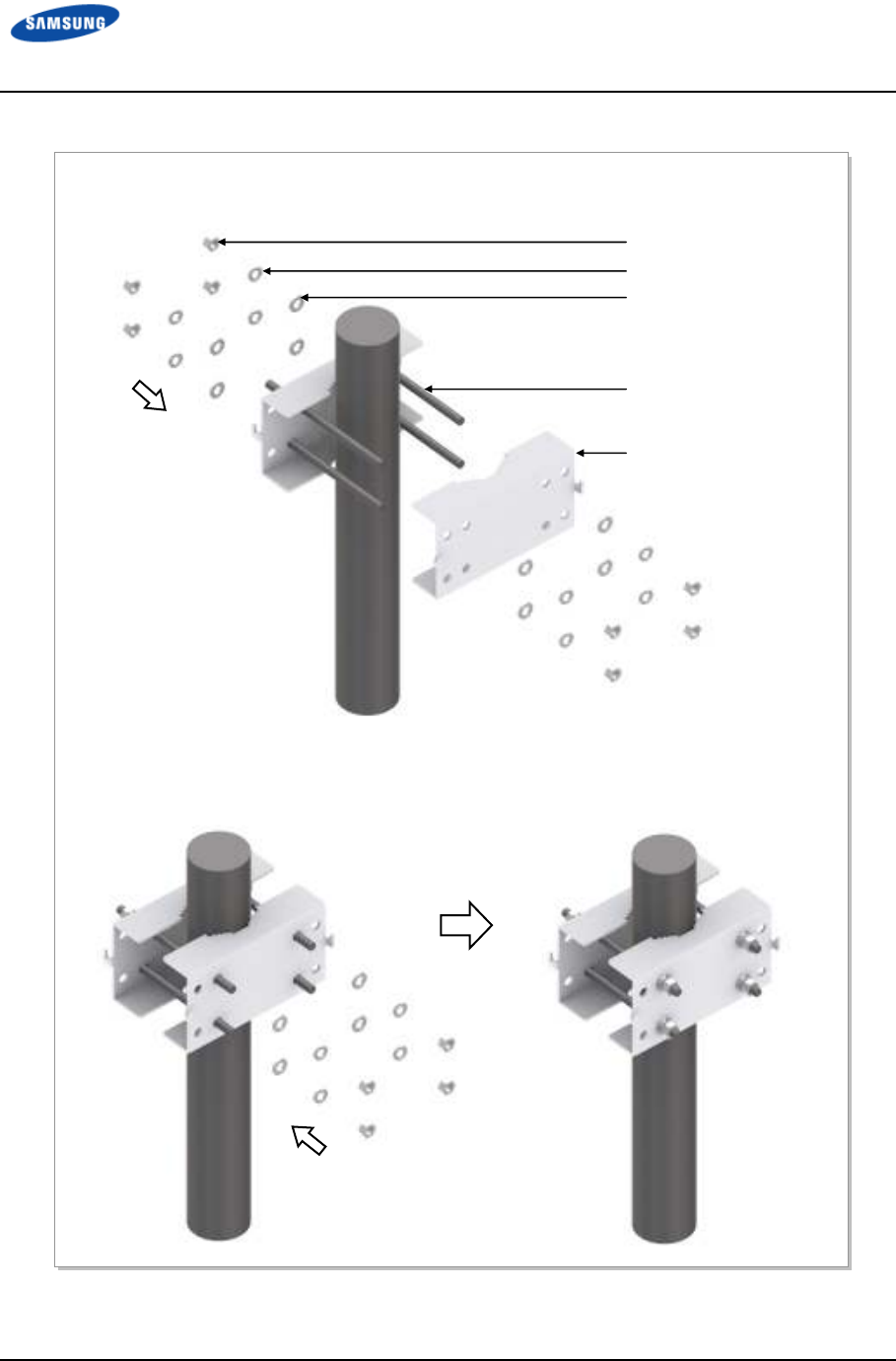
Fix the Outdoor Pico eNB (Pole Type)
The procedure for fixing the Outdoor Pico eNB on the 1-sector pole type is as
follows:
Fix Unit Mounting Bracket and Pole Mounting Bracket
Use Table 14. Unit/Pole Mounting Bracket Fixing Parts and Tools and Figure 11.
To Fix Unit Mounting Bracket and Pole Mounting Bracket to fix the unit mounting
bracket and pole mounting bracket.
Table 14. Unit/Pole Mounting Bracket Fixing Parts and Tools
Category
CategoryCategory
Category
Description
DescriptionDescription
Description
Parts Unit Mounting Bracket 1 EA
Pole Mounting Bracket 2 EA
Fastener M12 Stud Bolt
M12 Spring Washer
M12 Plain Washer
M12 Hex Nut
4 EA
8 EA
8 EA
8 EA
Recommended Torque Value M12 Hex Nut 21.11~31.67 lbfft
(292.0~438.0 kgfcm)
Working Tools Torque Wrench (Hexagon: 19 mm), Spanner
Error! Use the Home tab to apply 제목 1 to the text that you want to appear here.
Error! Use the Home tab to apply 제목 1 to the text that you want to appear here.
LTE TDD Outdoor Pico eNB Installation Manual v1.0 22
©Samsung Proprietary and Confidential
Figure 11. Fix Unit-Mounting Bracket and Pole-Mounting Bracket
1) Assemble the unit mounting bracket using the fasteners.
Pole Mounting Bracket
M12 Plain Washer
M12 Spring Washer
2) Adjust the pole mounting bracket to fit the M12 Stud bolts from the opposite side, and fix it securely
using the fasteners.
M12 Hex. Nut
M12 Stud Bolt
Error! Use the Home tab to apply 제목 1 to the text that you want to appear here.
Error! Use the Home tab to apply 제목 1 to the text that you want to appear here.
LTE TDD Outdoor Pico eNB Installation Manual v1.0 23
©Samsung Proprietary and Confidential
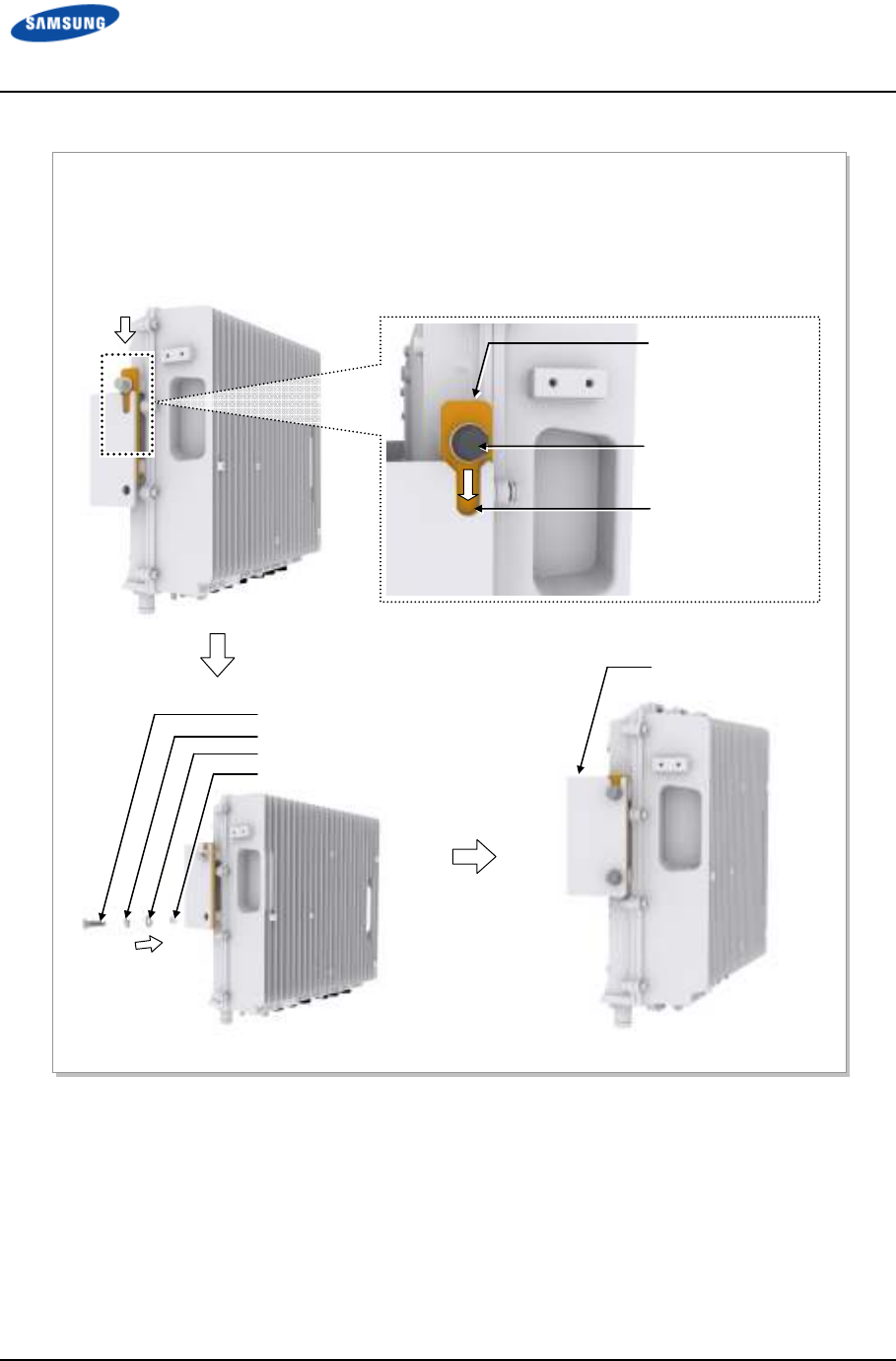
Fix the Outdoor Pico eNB
Use Table 15. Outdoor Pico eNB Fixing Parts and Tools (Pole Type) and Figure
12. To Fix the Outdoor Pico eNB–Pole Type (1) and Figure 13. Fixing the
Outdoor Pico eNB–Pole Type (2) to mount the Outdoor Pico eNB to the unit-
mounting bracket.
Table 15. Outdoor Pico eNB Fixing Parts and Tools (Pole Type)
Category
CategoryCategory
Category
Description
DescriptionDescription
Description
Parts M8 × 30L Hex Bolt 4 EA
M8 Spring Washer 4 EA
M8 Plain Washer 4 EA
M8 Insulation Bushing 4 EA
Bakelite (5T) 2 EA
M12 × 40L Hex Bolt 4 EA
M12 Spring Washer 8 EA
M12 Plain Washer 8 EA
M12 Hex. Nut 4 EA
Recommended Torque Value M8 Hex Bolt 8.82 lbfft (122 kgfcm)
M12 Hex Nut 21.11~31.67 lbfft
(292.0~438.0 kgfcm)
Working Tools Torque Wrench (Hexagon: 13 mm, 19 mm), Spanner
Error! Use the Home tab to apply 제목 1 to the text that you want to appear here.
Error! Use the Home tab to apply 제목 1 to the text that you want to appear here.
LTE TDD Outdoor Pico eNB Installation Manual v1.0 24
©Samsung Proprietary and Confidential
Figure 12. Fix the Outdoor Pico eNB–Pole Type (1)
Top groove of
Unit Mounting
Bracket
M8 × 30L Hex Bolt
Unit
Mounting Bracket
M8 Plain Washer
M8 Spring Washer
M8 × 30L Hex. Bolt
M8 Insulation Bushing
Unit Mounting Bracket
1) Hang M8 hex bolts, which are installed in the second fixing holes on the left/right sides of Outdoor Pico
eNB on the top groove of the unit-mounting bracket. Note that the plain washer and spring washer
should be located outside of the unit mounting bracket.
2) Assemble the unit mounting bracket and Outdoor Pico eNB using the fasteners.
Error! Use the Home tab to apply 제목 1 to the text that you want to appear here.
Error! Use the Home tab to apply 제목 1 to the text that you want to appear here.
LTE TDD Outdoor Pico eNB Installation Manual v1.0 25
©Samsung Proprietary and Confidential
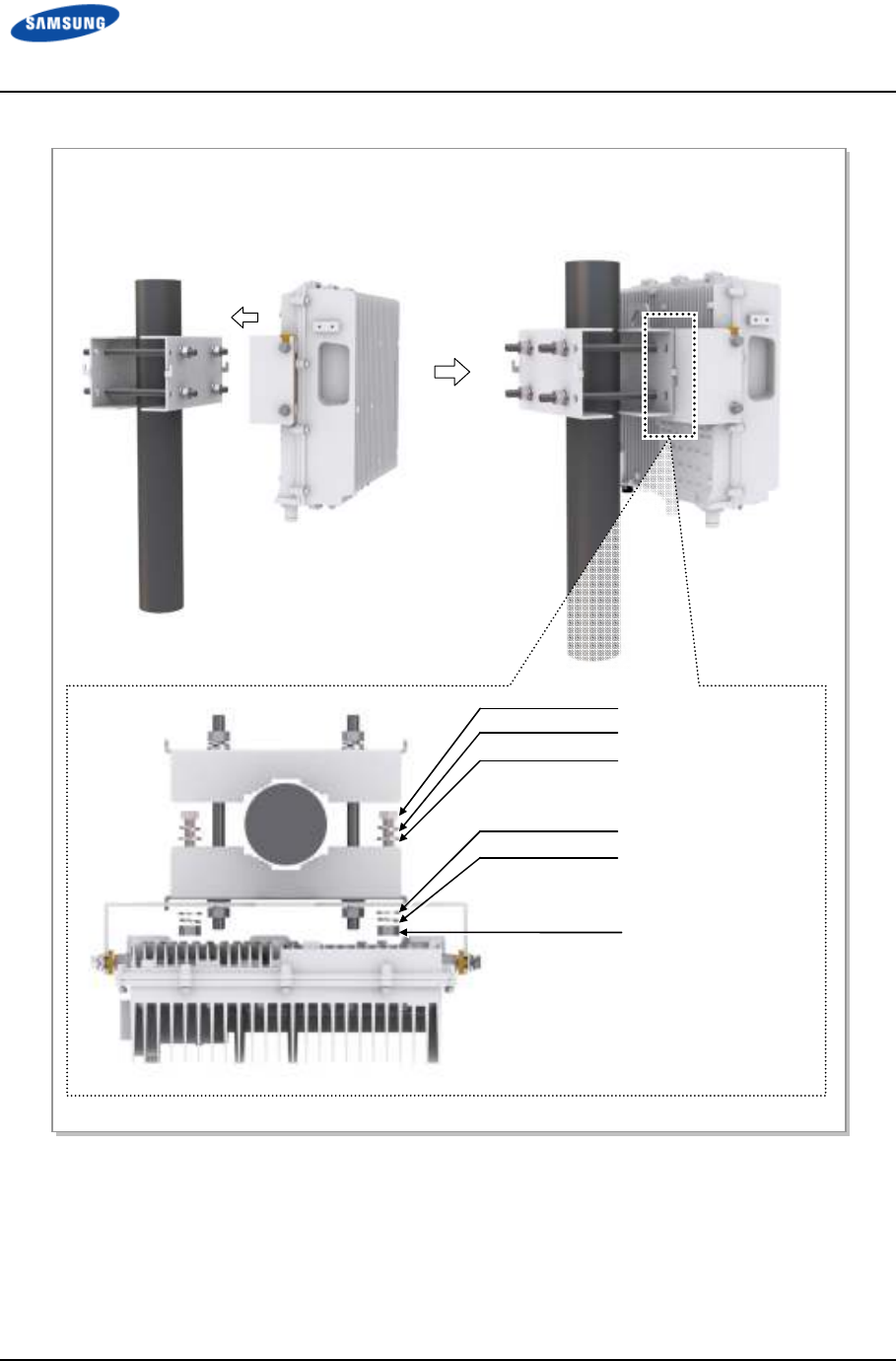
Figure 13. Fixing the Outdoor Pico eNB–Pole Type (2)
3) Align the grooves of the unit mounting bracket hook to the pole mounting bracket hook and hang it.
4) Fix the unit mounting bracket and the pole mounting bracket firmly to each other with the fastener.
M12 × 40L Hex. Bolt
M12 Spring Washer
M12 Plain Washer
M12 Plain Washer
M12 Spring Washer
M12 Hex. Nut
Error! Use the Home tab to apply 제목 1 to the text that you want to appear here.
Error! Use the Home tab to apply 제목 1 to the text that you want to appear here.
LTE TDD Outdoor Pico eNB Installation Manual v1.0 26
©Samsung Proprietary and Confidential
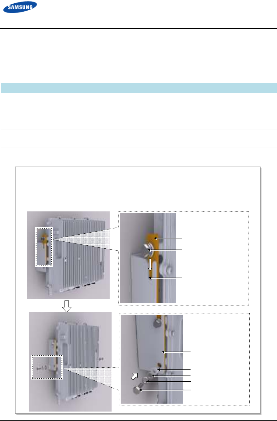
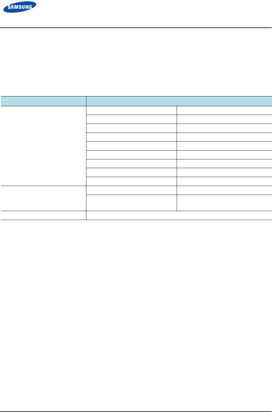
Installing GPS arrestor
Follow the steps below to install GPS arrestor to wall.
* Depending on site condition, install method of GPS arrestor may be vary.
Figure 14. Installing GPS arrestor (Wall)
Bulkhead
M6 Insulation Bushing
M6 Plain washer
M6 Spring washer
M6 Hex. Nut
Bakelite
M6 Anchor Bolt
GPS Arrestor
Bulkhead
N-Type Nut
Error! Use the Home tab to apply 제목 1 to the text that you want to appear here.
Error! Use the Home tab to apply 제목 1 to the text that you want to appear here.
LTE TDD Outdoor Pico eNB Installation Manual v1.0 27
©Samsung Proprietary and Confidential
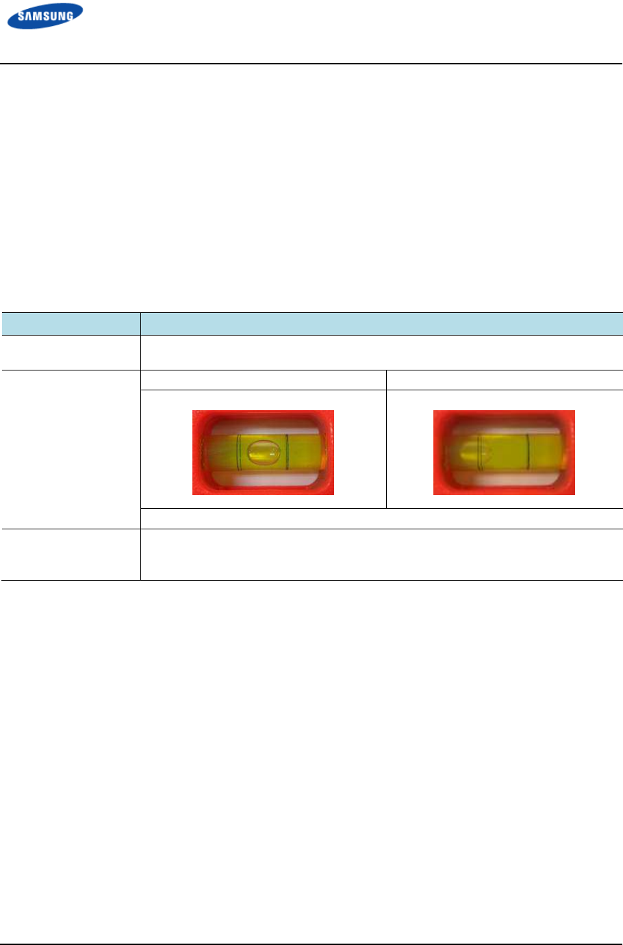
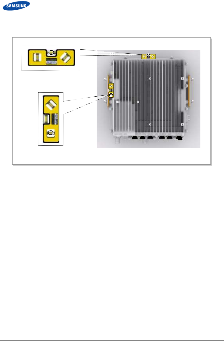
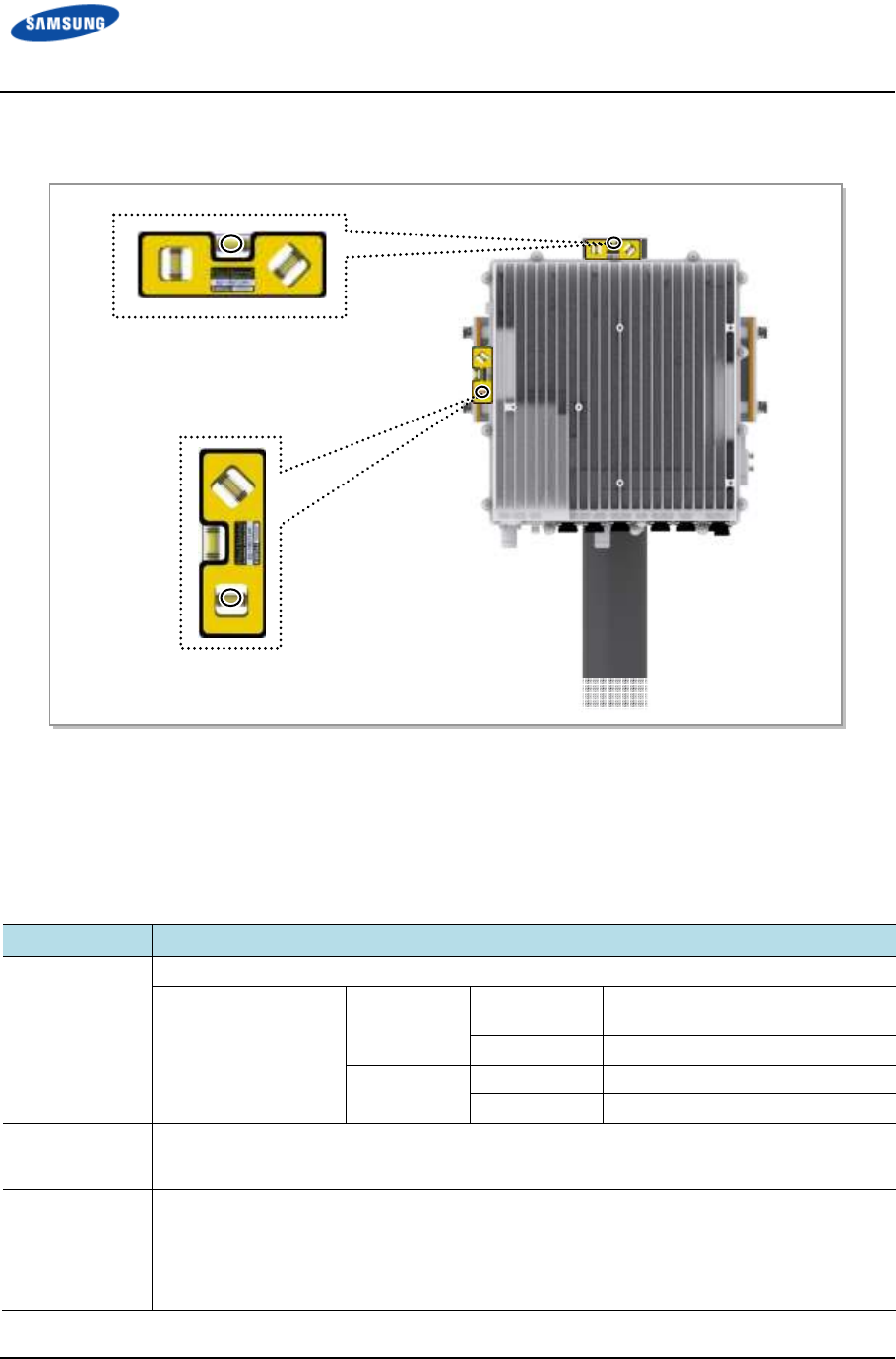
System Leveling
Leveling refers to compensating for the level difference on the floor when
installing devices horizontally or vertically. Leveling can be carried out using a
vinyl hose, a balance weight, or a level.
This section describes using a spirit level, a commonly used method.
Refer to Table 16. Leveling Using a Level and Figure 15. Leveling Using a Level
(Wall Type) and Figure 16. Leveling Using a Level (Pole Type) to use a spirit
level.
Table 16. Leveling Using a Level
Classification
ClassificationClassification
Classification
Description
DescriptionDescription
Description
Test Method The level is measured based on the position of a bubble after attaching the spirit level
to the top and side of the system.
Evaluation Criteria Good Poor
If it is level, the bubble of the spirit level is positioned at the center of both lines.
Corrective Measures
for Poor Leveling
Use an aid such as Bakelite or an auxiliary fixture on the backside of the system to
adjust the height.
Adjust the position of fasteners used to fix the system or its leveling status.
Error! Use the Home tab to apply 제목 1 to the text that you want to appear here.
Error! Use the Home tab to apply 제목 1 to the text that you want to appear here.
LTE TDD Outdoor Pico eNB Installation Manual v1.0 28
©Samsung Proprietary and Confidential
Figure 15. Leveling Using a Level (Wall Type)
[Measuring Horizontal Position]
[Wall Type]
[Measuring Vertical Position]
[Measuring Horizontal Position]
Error! Use the Home tab to apply 제목 1 to the text that you want to appear here.
Error! Use the Home tab to apply 제목 1 to the text that you want to appear here.
LTE TDD Outdoor Pico eNB Installation Manual v1.0 29
©Samsung Proprietary and Confidential
Figure 16. Leveling Using a Level (Pole Type)
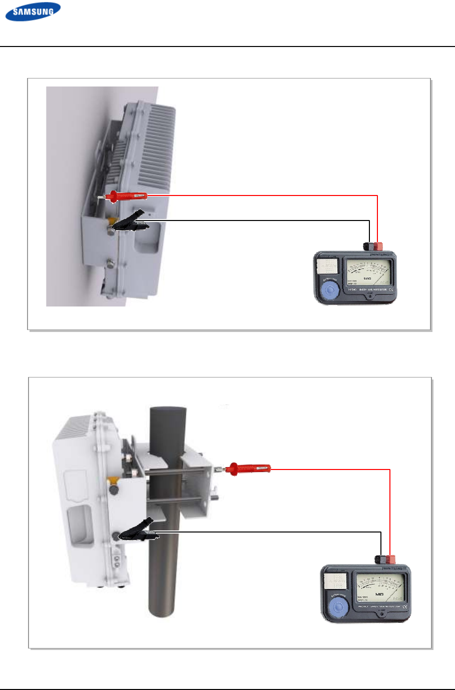
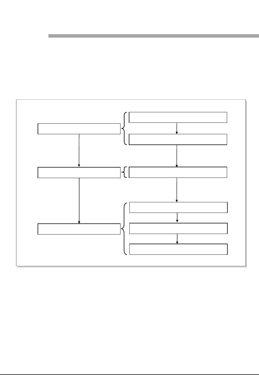
Insulation Test
The insulation test information is show in Table 17. Insulation Test.
Table 17. Insulation Test
Classification
ClassificationClassification
Classification
Description
DescriptionDescription
Description
Test Method The insulation tester (Megger) is used for measurement.
Position of lead line
of insulation tester
Wall Type Lead line_A Unit Mounting Bracket Fixing Hex.
Bolt
Lead line_B Outdoor Pico eNB Fixing Hex Bolt
Pole Type Lead line_A M12 Stud Bolt
Lead line_B Outdoor Pico eNB Fixing Hex Bolt
Evaluation
Criteria
• Good: 500 V/100 MΩ or more
• Poor: Less than 500 V/100 MΩ
Corrective
Measures for
Poor Leveling
• Check contact between the system and anchor bolt and re-assemble it.
(Note: The anchor bolt must be shielded using an insulator such as an insulation
bushing.)
• Check the damage of an insulator such as an insulation bushing or Bakelite, and replace
it accordingly.
[Measuring Vertical Position]
[Measuring Horizontal Position]
[Pole Type]
Error! Use the Home tab to apply 제목 1 to the text that you want to appear here.
Error! Use the Home tab to apply 제목 1 to the text that you want to appear here.
LTE TDD Outdoor Pico eNB Installation Manual v1.0 30
©Samsung Proprietary and Confidential
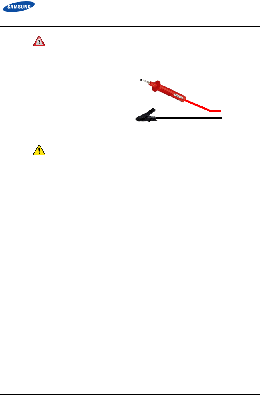
To prevent personal injury caused by an electric shock when using an insulation
tester, make sure the polarity is correct when connecting the Earth/Ground COM
(black) and AC.V (red) lead lines. Do not touch the connected probe inspecting
part of the lead line with your hands and avoid body contact.
Because there is very high voltage, observe the following to prevent any system
damage when measuring insulation resistance
- Before measuring insulation resistance, disconnect all cables connected to the
system.
- Do not measure insulation resistance when power is on.
- Do not measure insulation resistance at any position other than the target
insulation resistance measuring points.
Probe
(Inspecting part of the lead line)
Error! Use the Home tab to apply 제목 1 to the text that you want to appear here.
Error! Use the Home tab to apply 제목 1 to the text that you want to appear here.
LTE TDD Outdoor Pico eNB Installation Manual v1.0 31
©Samsung Proprietary and Confidential
Figure 17. Schematic Diagram for Insulation Test (Wall Type)
Figure 18. Schematic Diagram for Insulation Test (Pole Type)
Unit Mounting Bracket Fixing Hex. Bolt
[
Megger
]
[Wall Type]
Outdoor Pico eNB
Fixing Hex Bolt
[Megger]
[Pole Type]
M12 Stud Bolt
Outdoor Pico eNB Fixing Hex Bolt
LTE TDD Outdoor Pico eNB Installation Manual v1.0 32
©Samsung Proprietary and Confidential
Chapter 3
Chapter 3Chapter 3
Chapter 3 Connecting
Connecting Connecting
Connecting
Cables
CablesCables
Cables
Work Flow for Cabling
Figure 19. Work Flow for System Cabling shows the system cable.
Figure 19. Work Flow for System Cabling
Grounding
Power Cabling
System Ground Cable Connection
External Interface Construction
Backhaul Cable Connection
GPS Cable Connection
RF Cable Connection
System Power Cable Connection
GPS Arrestor Ground Cable Connection
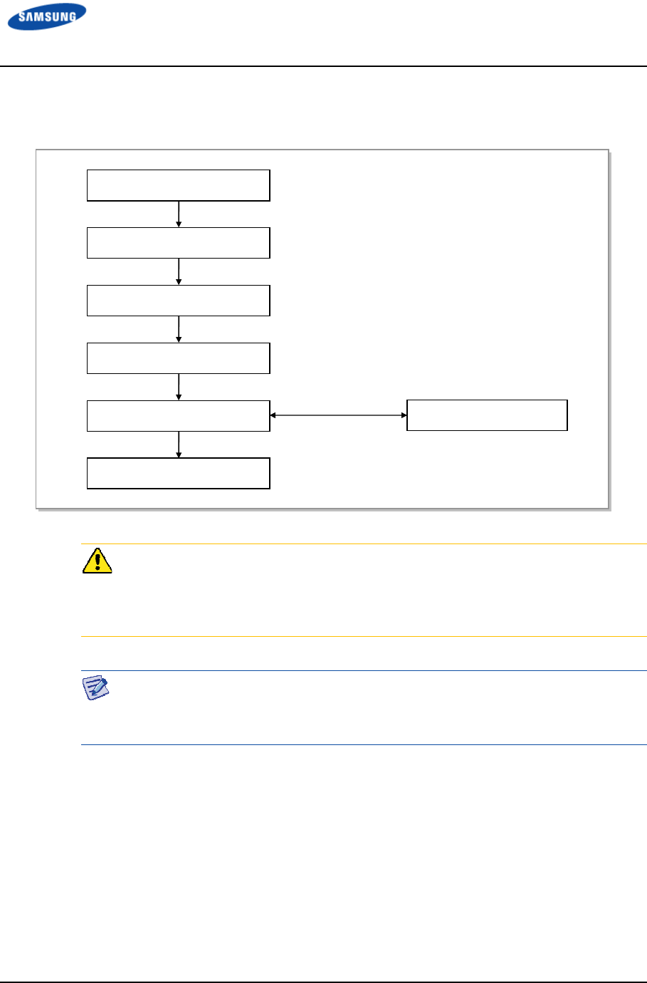
Error! Use the Home tab to apply 제목 1 to the text that you want to appear here.
Error! Use the Home tab to apply 제목 1 to the text that you want to appear here.
LTE TDD Outdoor Pico eNB Installation Manual v1.0 33
©Samsung Proprietary and Confidential
Figure 20. Detailed Cabling Procedure shows the detailed procedure of cabling.
Figure 20. Detailed Cabling Procedure
Before cutting the cable after installation, make sure that the connector is
disconnected from the equipment. Installation of the cable with the connector
connected to the system may cause failure or damage to the connector assembled
to the system and the cable.
The sequence of cable cutting and installation of the cable workflow can be
changed depending on the field situation, such as ‘cutting after installing’ or
‘installing after cutting’.
Cable Installation
Cable Binding
Connector Attachment
Identification Tag Attachment
Connector Assembly
When assembling the
connector at the site
Cable Path Inspection
Cable Cutting

Error! Use the Home tab to apply 제목 1 to the text that you want to appear here.
Error! Use the Home tab to apply 제목 1 to the text that you want to appear here.
LTE TDD Outdoor Pico eNB Installation Manual v1.0 34
©Samsung Proprietary and Confidential
Cable Path Inspection
When installing a cable that connects between the AC distributor, Ground Bar, and
backhaul device within the system, inspect the cable path, length, and installation
method.
Follow these guidelines while inspecting the cabling path:
• Select a minimum cable length provided it does not affect the cable installation
and maintenance.
• Place the cable in a location where it will not be damaged by external factors
(power line, flooding, footpaths, and so on).
• In areas where the cable may be damaged by external factors, ensure that
measures are taken to prevent damage to the cable (cable tray, ducts, and
flexible pipe).
Cable Cutting
Measure the exact distance and carefully check the route. Cut the cable using a
cutting tool.
Follow these guidelines while cutting the cable:
• Cut the cable to the length determined in the ‘Cable Path Inspection’ step.
• Use a cable-cutting tool specific to the cable.
• Cut the cable at right angles.
• Be careful to keep the cable away from any moisture, iron, lead, dust, or other
foreign material while cutting.
• Remove any foreign material attached to the cable using solvent and a brush.
Cable Installation
Cable installation involves running the cable along a path to the system target
connector or to an auxiliary device after path inspection and cable cutting
completion.
Follow these guidelines while installing a cable:
• Do not damage the cable.
• If the cable is damaged, cut the damaged section before installation or replace
the cable.
• Run the cable to avoid any knots. While installing the cable from a horizontal
section to a vertical section, exercise extra care so that the upper and lower
lines of the cable are not reversed.

Error! Use the Home tab to apply 제목 1 to the text that you want to appear here.
Error! Use the Home tab to apply 제목 1 to the text that you want to appear here.
LTE TDD Outdoor Pico eNB Installation Manual v1.0 35
©Samsung Proprietary and Confidential
• Always use the maximum possible curvature radius, and make sure that it is in
compliance with the minimum curvature radius specification.
• To protect the cable, use a PVC channel, spiral sleeve, flexible pipe, and cable
tray.
Table 18. Minimum Recommended Cable Bend Radius
No
NoNo
No
Type
TypeType
Type
Allowed Cable Bend Radius
Allowed Cable Bend RadiusAllowed Cable Bend Radius
Allowed Cable Bend Radius
Remark
RemarkRemark
Remark
1 F-GV/F-CV/FR-8 8 times of the cable external diameter 0.6/1 KV Cable
2 Optic Cable 20 times of the cable external diameter -
3 UTP/FTP/S-FTP Cable 4 times of the cable external diameter PVC/LSZH, 4 Pair
4 1/2 in. Feeder Line (Indoor) 1.26 in. (32 mm) RFS, LS
5 1/2 in. Feeder Line (Outdoor) 4.92 in. (125 mm) RFS, LS
6 7/8 in. Feeder Line (Outdoor) 9.84 in. (250 mm) RFS, LS
7 1-1/4 in. Feeder Line (Outdoor) 14.96 in. (380 mm) RFS, LS
8 1-5/8 in. Feeder Line (Outdoor) 19.69 in. (500 mm) RFS, LS
9 RG-316D 0.59 in. (15 mm) -
It should be in compliance with it the allowed cable bend radius as specified by the manufacturer.
Cable Binding
Cable binding involves fixing and arranging an installed cable using binding
thread, cable ties, binding wire, and ram clamps.
Follow these guidelines while binding a cable:
• Do not damage the cable during binding.
• Use appropriate cable binding tools according to the target location (indoor or
outdoor) with accordance to the use of the cable (for example, power supply
cable, optical cable, or feeder line).
• Do not let the cutting section of a cable tie and binding line be exposed to the
outside. This may cause damage to cables or personal injury.
• Cut off the remainder of the cable binding thread by leaving about 1.97 in.(50
mm) of extra length and put it through the knot so that it stays secured.
• Install the cable as short as possible to limit the danger of contact failure in a
connector connection due to tension.
Error! Use the Home tab to apply
Error! Use the Home tab to apply
LTE TDD Outdoor Pico eNB
Installation Manual
©Samsung Proprietary and Confidential
Connector Attachment
Connector attachment involves
or to a device on the site.
Follow these
•
Make sure
assembling a connector. Assemble the connector in accordance with its pin
map.
•
Each connector has a latch to prevent its core positions from being changed.
• Check
for a
connector.
• Use a
customer approved weatherproof method
that are installed outdoor
corrosion fr
•
Connect each cable of the connector assembly in a straight line.
•
Make sure
Identification Tag Attachment
Identification tag attachment involves
label to
both ends of
cabling path.
A label can be attached on
The appearance and specification may differ depending
on
the type and manufacturer.
Follow these guidelines when attaching an identification tag.
•
When installing a cable outdoor
prevent the markings from being erased.
•
Since the form and attachment method for identifica
each provider, consult with the provider before attaching them.
A
lways connect the ground cable first
due to static electricity and short circuit.
Cover the unused ports with
of foreign material such as dust, moisture
Error! Use the Home tab to apply
제목
1 to the text that you want to appear here.
Error! Use the Home tab to apply
제목
1 to the text that you want to appear here.
Installation Manual
v1.0
©Samsung Proprietary and Confidential
Connector Attachment
Connector attachment involves
the assembling of
a connector to an installed cable
or to a device on the site.
guidelines while attaching a connector.
Make sure
that
you are fully aware of the connector assembly method before
assembling a connector. Assemble the connector in accordance with its pin
Each connector has a latch to prevent its core positions from being changed.
for a
corresponding grooves before connecting
one
connector.
customer approved weatherproof method
at all the
connector
that are installed outdoor
s
, such as feeder lines, to prevent water leakage and
corrosion fr
om occurring at the connection.
Connect each cable of the connector assembly in a straight line.
Make sure
that
there is no cable strain by using extra cable length or cable ties.
Identification Tag Attachment
Identification tag attachment involves
attaching a marker cable tie, nameplate
both ends of
the
cable (connections to a connector) to identify its use and
A label can be attached on
the marker cable tie.
The appearance and specification may differ depending
the type and manufacturer.
Follow these guidelines when attaching an identification tag.
When installing a cable outdoor
s
, use relief engraving and coated labels to
prevent the markings from being erased.
Since the form and attachment method for identifica
tion tags are different for
each provider, consult with the provider before attaching them.
lways connect the ground cable first
to prevent
system damage or worker
due to static electricity and short circuit.
Cover the unused ports with
a water
proof cap (sealing cap) to prevent infiltration
of foreign material such as dust, moisture
, or insects.
1 to the text that you want to appear here.
1 to the text that you want to appear here.
36
a connector to an installed cable
you are fully aware of the connector assembly method before
assembling a connector. Assemble the connector in accordance with its pin
Each connector has a latch to prevent its core positions from being changed.
one
connector to another
connector
s for cables
, such as feeder lines, to prevent water leakage and
Connect each cable of the connector assembly in a straight line.
there is no cable strain by using extra cable length or cable ties.
attaching a marker cable tie, nameplate
, and
cable (connections to a connector) to identify its use and
, use relief engraving and coated labels to
tion tags are different for
each provider, consult with the provider before attaching them.
system damage or worker
injury
proof cap (sealing cap) to prevent infiltration
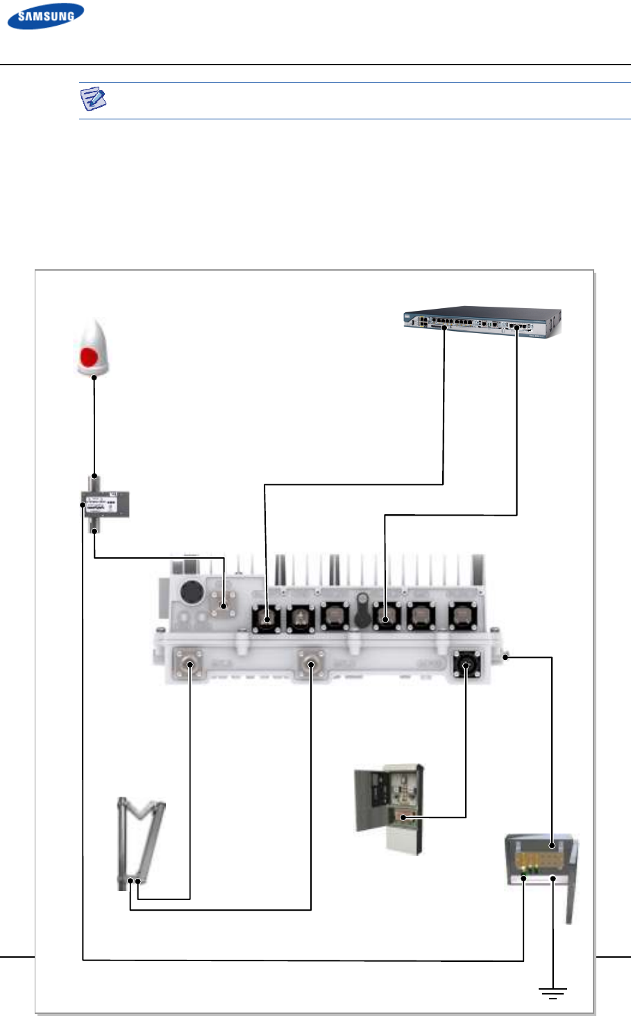
Error! Use the Home tab to apply 제목 1 to the text that you want to appear here.
Error! Use the Home tab to apply 제목 1 to the text that you want to appear here.
LTE TDD Outdoor Pico eNB Installation Manual v1.0 37
©Samsung Proprietary and Confidential
Make sure the work is done by personnel properly trained for the job.
Cabling
Figure 21. Cabling Diagram shows the cabling of the Outdoor Pico eNB.
Figure 21. Cabling Diagram
7) RF Cable
[AC Distributor]
[Ground Bar]
[RF Antenna]
[SAR, Site Aggregation Router]
3) AC Power Cable
5) Backhaul Ethernet Cable
[GPS Antenna]
5) GPS Cable
[GPS Arrestor]
4) Backhaul Optic Cable
6) GPS Cable
1) Ground Cable
2) GPS Arrestor Ground Cable
7) RF Cable

Error! Use the Home tab to apply 제목 1 to the text that you want to appear here.
Error! Use the Home tab to apply 제목 1 to the text that you want to appear here.
LTE TDD Outdoor Pico eNB Installation Manual v1.0 38
©Samsung Proprietary and Confidential
Table 19. Outdoor Pico eNB Connection Cable
From
FromFrom
From
To
ToTo
To
Cable
CableCable
Cable
Ground Bar Outdoor Pico eNB 1 Ground Cable
: AWG 8, F-GV 6 mm
2
× 1C
2 hole lug : Ex) Manufacturer: Panduit, LCD8-14AF-L
or equivalent
GPS Arrestor 2 GPS Arrestor Ground Cable
: AWG 10, F-GV 4 mm
2
× 1C
AC Distributor Outdoor Pico eNB 3 AC Power Cable
: AWG 16 × 3C
Outdoor Pico eNB Site Aggregation
Router
4 Backhaul Cable (Optic)
: Single Mode Outdoor, 2LC/UPC
5 Backhaul Cable (Copper)
: S-FTP, Cat.5e or Cat.6, 4 Pair
GPS Antenna 6 GPS Cable
: 1/2 in. Coaxial Cable
Connector: N Type-Male
RF Antenna 7 RF Cable
: 1/2 in. Feeder Line
Connector: Mini DIN Type-Male
Error! Use the Home tab to apply 제목 1 to the text that you want to appear here.
Error! Use the Home tab to apply 제목 1 to the text that you want to appear here.
LTE TDD Outdoor Pico eNB Installation Manual v1.0 39
©Samsung Proprietary and Confidential
Grounding
Grounding is required for protecting the electric systems such as power system,
communication system, and control system, from lightning, excessive-current,
high-voltage, and electric noise. Grounding will substantially reduce the possibility
of accidents, especially when used in combination with other safety measures.
The purpose of grounding is as follows:
• To prevent human life and the system from excessive current, high-voltage,
and lightning
• To provide a discharge path for surge voltage generated by lightning and
power switch
• To protect the system from static electricity
• To eliminate or minimize the high-frequency potential in system housing
• To stabilize the potential of the circuit against the ground
Connecting cables without the ground cable may cause damage to the equipment
or physical injury to the worker. Always connect the ground cable.
Ground bar for lightning protector/power/communication must be isolated from
each other. These three ground bars can be grounded using the isolation grounding
method, or branched from ground mesh buried in the ground using the common
grounding method.
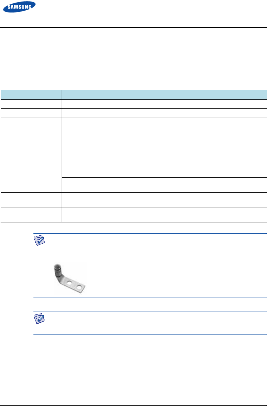
Error! Use the Home tab to apply 제목 1 to the text that you want to appear here.
Error! Use the Home tab to apply 제목 1 to the text that you want to appear here.
LTE TDD Outdoor Pico eNB Installation Manual v1.0 40
©Samsung Proprietary and Confidential
Grounding the Outdoor Pico eNB
Table 20. Grounding the Outdoor Pico eNB and Figure 22. Connection of the
Outdoor Pico eNB Ground Cable show the procedure to connect the ground cable
of the Outdoor Pico eNB.
Table 20. Grounding the Outdoor Pico eNB
Category
CategoryCategory
Category
Description
DescriptionDescription
Description
Installation Section Ground Bar - Outdoor Pico eNB Ground Terminal
Cable AWG 8, F-GV 6 mm
2
× 1C, Yellow/Green
Heat Shrink Tube
(Spec/Color/Length)
Φ 12 mm/Green/50 mm
Pressure Terminal Ground Bar Check Ground Bar specifications per site and preparing
connecting parts
Outdoor Pico
eNB
6 mm
2
, 2 Hole, 90°, Hole Dia.: 6.3 mm, Hole Dist.: 16 mm
Fastener Ground Bar Check Ground Bar specifications per site and preparing
connecting parts
Outdoor Pico
eNB
M6 × 12L SEMS/ 2 EA
Recommended Torque
Value
M6 SEMS 2.41~3.61 lbf.ft (33.28~49.92 kgf·cm)
Working Tools Cable Cutter, Wire Stripper, Compressor, Heating Gun, Torque Driver(+), Torque
Wrench, Nipper
Use UL certified products or equivalent for the pressure terminal and cables.
Example: Manufacturer - Panduit
Outdoor Pico eNB: 6 mm
2
Pressure Terminal (LCD8-14AF-L)
Refer to ‘Appendix F Pressure Terminal Assembly’ to see how to assemble a
pressure terminal and a heat shrink tube to a cable.
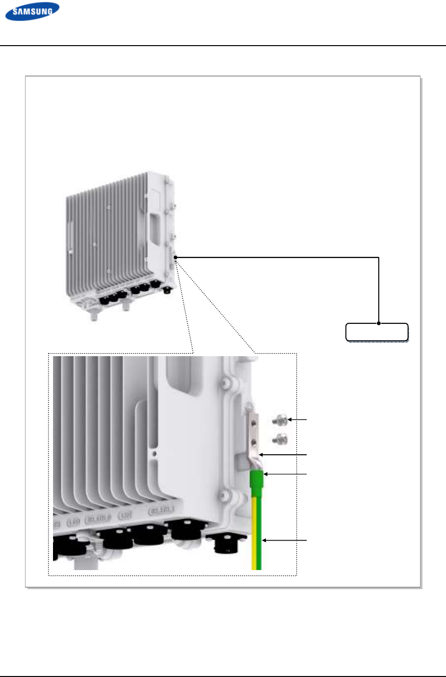
Error! Use the Home tab to apply 제목 1 to the text that you want to appear here.
Error! Use the Home tab to apply 제목 1 to the text that you want to appear here.
LTE TDD Outdoor Pico eNB Installation Manual v1.0 41
©Samsung Proprietary and Confidential
Figure 22. Connection of the Outdoor Pico eNB Ground Cable
1) Install the ground cable from the Ground Bar to the Outdoor Pico eNB ground terminal.
2) Assemble a pressure terminal and a heat shrink tube at the end of the Outdoor Pico eNB ground cable.
3) Align the pressure terminal to the mounting hole of the Outdoor Pico eNB ground terminal.
4) Firmly fix the pressure terminal onto the Outdoor Pico eNB ground terminal using fasteners.
M6 × 12L SEMS
Pressure Terminal
Ground Cable
Heat Shrink Tube (Green)
Ground Bar
Ground Cable (AWG 8, F-GV 6 mm
2
× 1C)
[Outdoor Pico eNB]
Error! Use the Home tab to apply 제목 1 to the text that you want to appear here.
Error! Use the Home tab to apply 제목 1 to the text that you want to appear here.
LTE TDD Outdoor Pico eNB Installation Manual v1.0 42
©Samsung Proprietary and Confidential
Grounding GPS Arrestor
Follow the steps below to connect the ground cable to the UADU.
* Depending on site condition, install method of GPS arrestor may be vary.
Table 21. Grounding GPS Arrestor
Category
CategoryCategory
Category
Description
DescriptionDescription
Description
Installation Section Ground Bar - GPS Arrestor Grounding Terminal
Cable AWG 10, F-GV 4 mm
2
× 1C, Yellow/Green
Heat Shrink Tube
(Spec/Color/Length)
Φ 12 mm/Green/50 mm
Pressure Terminal Ground Bar Check Ground Bar specifications per site and preparing
connecting parts
GPS Arrestor 4 mm
2
, Ring Type, Hole Dia.: 8.3 mm
Fastener Ground Bar Check Ground Bar specifications per site and preparing
connecting parts
GPS Arrestor M8 Hex. Bolt/ 1EA
M8 Spring Washer/ 1EA
M8 Plain Washer/ 1EA
Recommended Torque
Value
M8 Hex. Bolt 5.96~8.94 lbf.ft (82.4~123.6 kgf·cm)
Working Tools Cable Cutter, Wire Stripper, Compressor, Heating Gun, Torque Driver(+), Torque
Wrench, Nipper
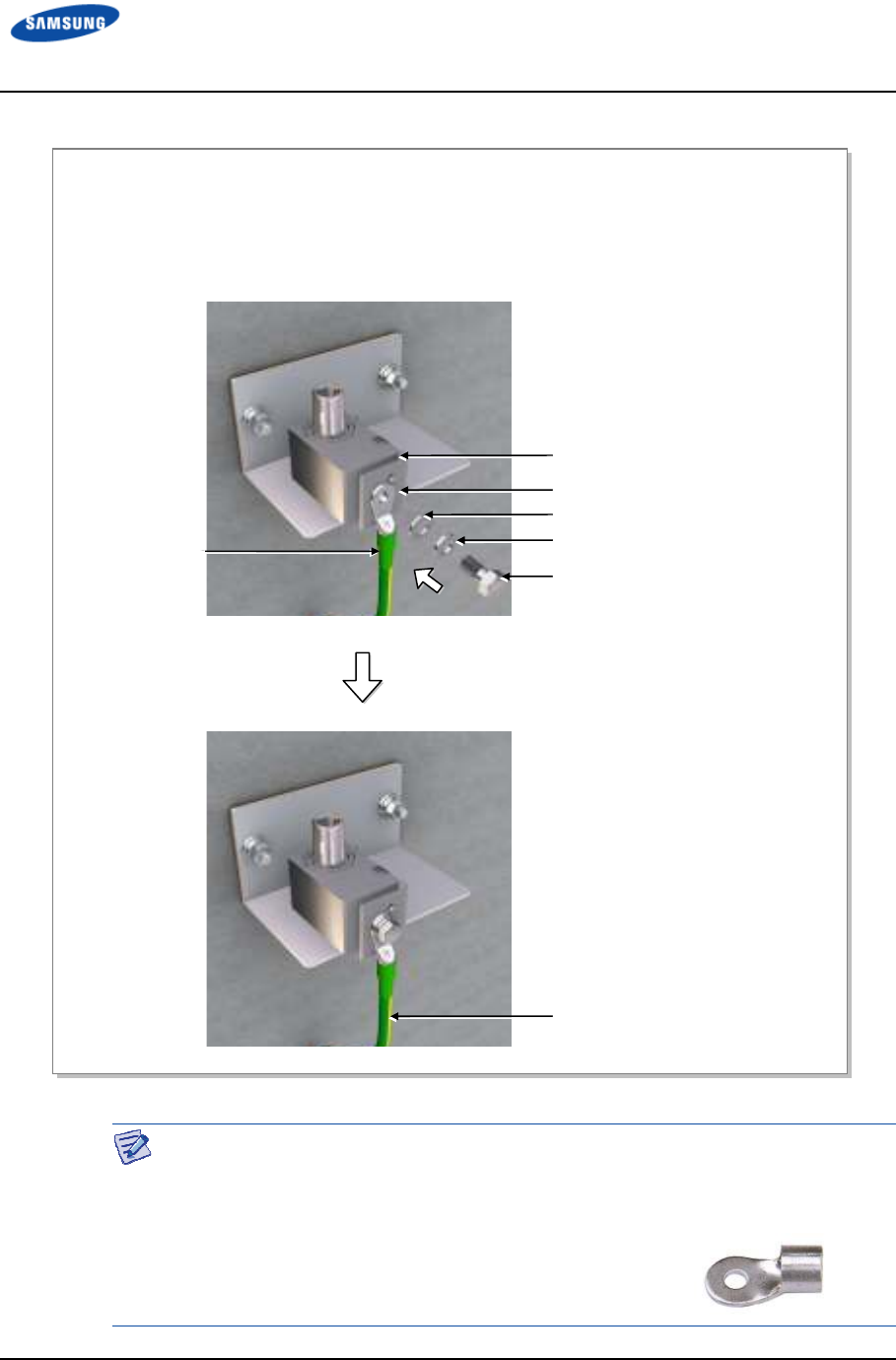
Error! Use the Home tab to apply 제목 1 to the text that you want to appear here.
Error! Use the Home tab to apply 제목 1 to the text that you want to appear here.
LTE TDD Outdoor Pico eNB Installation Manual v1.0 43
©Samsung Proprietary and Confidential
Figure 23. Connecting GPS Arrestor ground cable
Pressure terminal
As for the pressure terminal or the cable, the UL Listed or equivalent should be
used.
Example: Manufacturer-JEONO Electric
- GPS Arrestor: 4 mm² Type Name(JOR 4-8)
GPS Arrestor
4 mm² Pressure Terminal (Ring type)
M8 Plain washer
M8 Spring washer
M8 Hex. Bolt
GPS Arrestor Ground Cable
(F-GV 4 mm² × 1C) From Ground Bar
Heat Shrink Tube
(Green)
1) Install the ground cable from the ground bar to the ground connector of the GPS arrestor.
2) Install the 4 mm² pressure terminal and the heat shrink tube at the end of the cable.
Pressure terminal: 4 mm², ring type, hole diameter: 8.3 mm
3) Align the assembled pressure terminal to the GPS arrestor fixing holes at the ground cable on the GPS
arrestor, and then fix it with the M8 plain washer, spring washer, Hex. bolt.

Error! Use the Home tab to apply 제목 1 to the text that you want to appear here.
Error! Use the Home tab to apply 제목 1 to the text that you want to appear here.
LTE TDD Outdoor Pico eNB Installation Manual v1.0 44
©Samsung Proprietary and Confidential
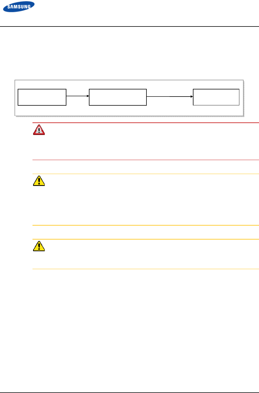
Error! Use the Home tab to apply 제목 1 to the text that you want to appear here.
Error! Use the Home tab to apply 제목 1 to the text that you want to appear here.
LTE TDD Outdoor Pico eNB Installation Manual v1.0 45
©Samsung Proprietary and Confidential
Power Cabling
Figure 24. Power Equipment Diagram shows how the power supply is configured.
Figure 24. Power Equipment Diagram
Be sure to check the AC distributor circuit breaker is turned off before connecting
the power cable to power connector. If the system is installed while the circuit
breaker is on, the worker may be critically injured if the cable is connected
incorrectly.
When Using Power Cables
- Ensure the AC distributor power switch or that of the system is turned off to
prevent short-circuiting of related cables.
- Because a power accident may occur due to loose parts, make sure that fasteners
are firmly fixed.
- For supply connections, use wires suitable for at least 90°C.
SPD
- AC SPD Type 2 or Type 1 with 2500Vmax limit must be installed externally
ex) Raycap Part Number :AC1060-02W-NA
AC
AC Distributor
(Uninterruptible Power)
Commercial Power System
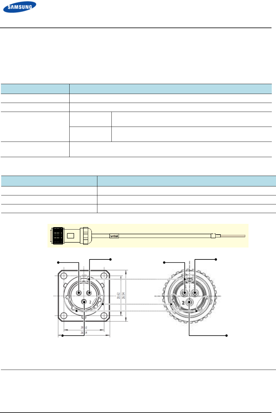
Error! Use the Home tab to apply 제목 1 to the text that you want to appear here.
Error! Use the Home tab to apply 제목 1 to the text that you want to appear here.
LTE TDD Outdoor Pico eNB Installation Manual v1.0 46
©Samsung Proprietary and Confidential
Connecting the AC Power Cable
Use the following tables and figures to connect the AC power cable to the Outdoor
Pico eNB.
Table 22. Connecting the AC Power Cable
Category
CategoryCategory
Category
Description
DescriptionDescription
Description
Installation Section AC Distributor - Outdoor Pico eNB Power Input Terminal
Cable AWG16 × 3C
Connector AC Distributor Check the specification of AC distributor output terminal and
prepare fasteners.
Outdoor Pico
eNB
JONHON, DY5T1203SNF, Straight Plug
Working Tools Cable Cutter, Wire Stripper, Compressor, Heating Gun, Torque Driver(+),
Torque Wrench, Nipper, Soldering Iron, and Lead
Table 23. Power Connector Pin Map
No.
No.No.
No.
Color
ColorColor
Color
1 (L) Black
2 (PE) Yellow/green
3 (N) White
3 3 1 1
2 2
[System-side Connector: DY5F1203PNF]
[Cable-side Connector: DY5T1203SNF]
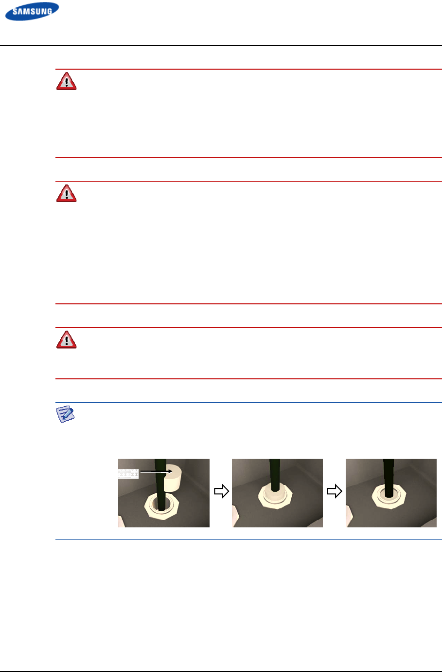
Error! Use the Home tab to apply 제목 1 to the text that you want to appear here.
Error! Use the Home tab to apply 제목 1 to the text that you want to appear here.
LTE TDD Outdoor Pico eNB Installation Manual v1.0 47
©Samsung Proprietary and Confidential
Do not rapidly turn the system ON/OFF (within one second): The Outdoor Pico
eNB could be damaged by the counter electromotive force caused by the cable
inductance.
- Do not use the power cables linked or power loss will increase.
- For the length of the AC power cable, follow the safety regulation of the
installation site.
To prevent foreign substances, outdoor air, and moisture from entering the system
input/output port and cable inlet (including cable gland and conduit), finish it as
follows:
- Unused inlet
Use the hole finishing materials including waterproof cap and rubber packing.
- Cable-installed port and cable inlet
- After cable installation, block any space in the inlet with tape, compressed
sponge, rubber packing, and silicon.
The pin map provided by this manual is based on the connectors on the system
side, so it is necessary to check the pin connection positions when connecting to
the cable side.
When laying the power cable through the input/output port (conduit) at the bottom
of the AC distributor, a sealing material should be used to prevent foreign
substances from coming
Sealing material
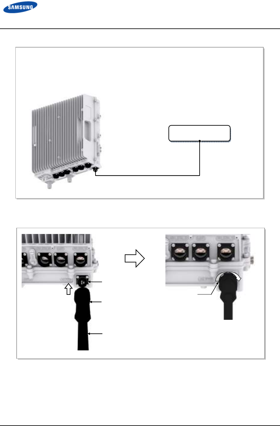
Error! Use the Home tab to apply 제목 1 to the text that you want to appear here.
Error! Use the Home tab to apply 제목 1 to the text that you want to appear here.
LTE TDD Outdoor Pico eNB Installation Manual v1.0 48
©Samsung Proprietary and Confidential
Figure 25. Connecting the Outdoor Pico eNB Power Cable (1)
Figure 26. Connecting the Outdoor Pico eNB Power Cable (2)
AC Distributor
(120~240 V AC)
1) Worker shall install a power cable from the AC distributor to the power input port of the Outdoor Pico eNB.
2) Assemble a connector to the end of power cable (Outdoor Pico eNB-side).
3) Connect the power cable assembled with the power connector to the power port of the Outdoor Pico eNB.
4) Turn the connector coupling nut clockwise on the cable and fix it.
AC Power Cable (AWG16 × 3C)
[Outdoor Pico eNB]
Power Connector
AC
Power Cable
Power Input Port
(120~240 V AC)
Coupling Nut
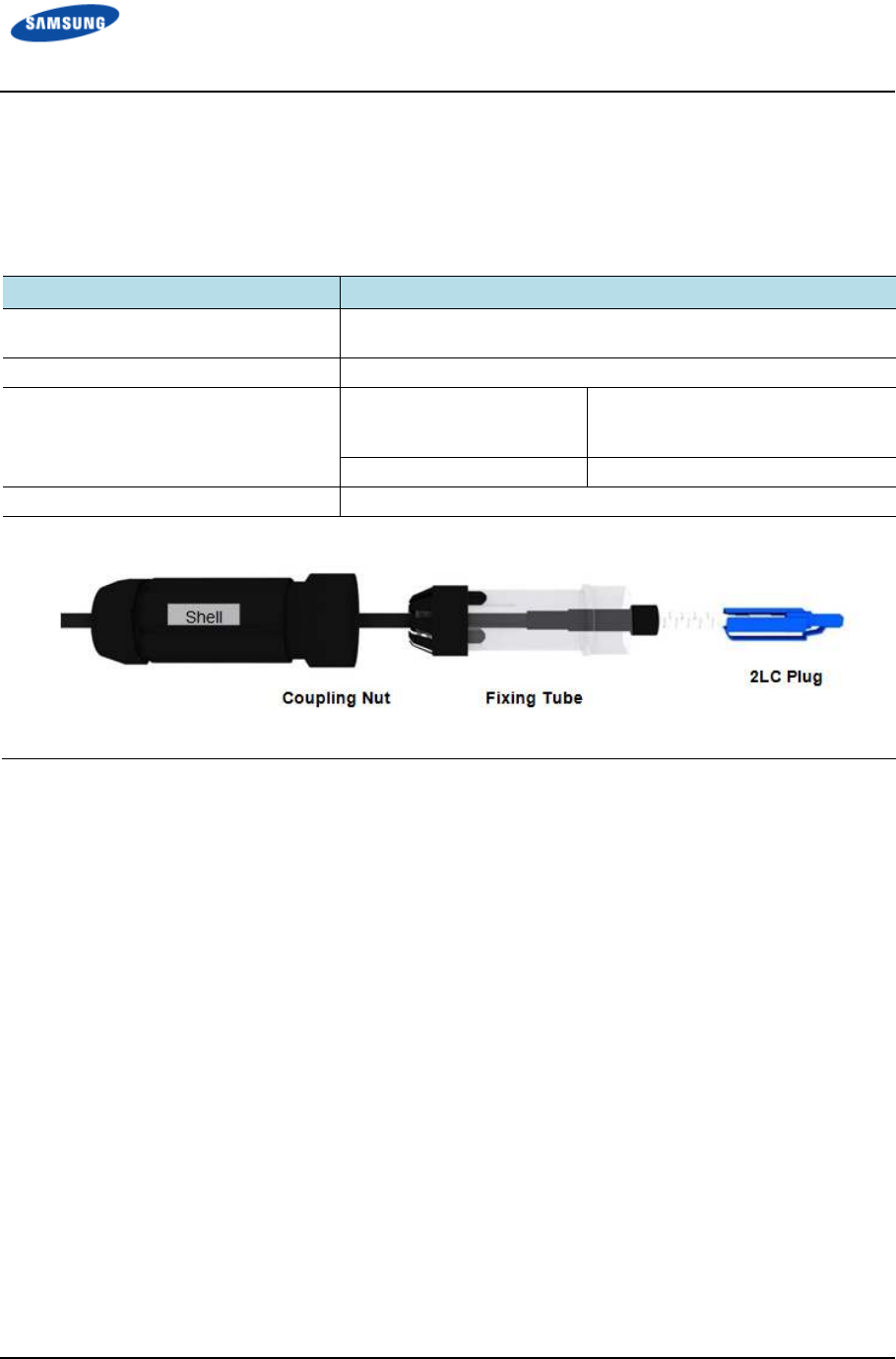
Error! Use the Home tab to apply 제목 1 to the text that you want to appear here.
Error! Use the Home tab to apply 제목 1 to the text that you want to appear here.
LTE TDD Outdoor Pico eNB Installation Manual v1.0 49
©Samsung Proprietary and Confidential
Backhaul Cable Connection (Optic Type)
Follow the steps below to connect the backhaul cable (Optic type) to the Outdoor
Pico eNB.
Table 24. Backhaul Cable Connection (Optic Type)
Category
CategoryCategory
Category
Description
DescriptionDescription
Description
Installation Section Site Aggregation Router ~ Outdoor Pico eNB_Backhaul (BH_OPT)
Port
Cable Optic Cable(Single Mode, Outdoor)
Connector Site Aggregation Router Checking Site Aggregation Router
side connector specifications and
preparing connecting parts.
Outdoor Pico eNB PDLC, 2LC/UPC[JONHON]
Working Tools Optic Cleaner
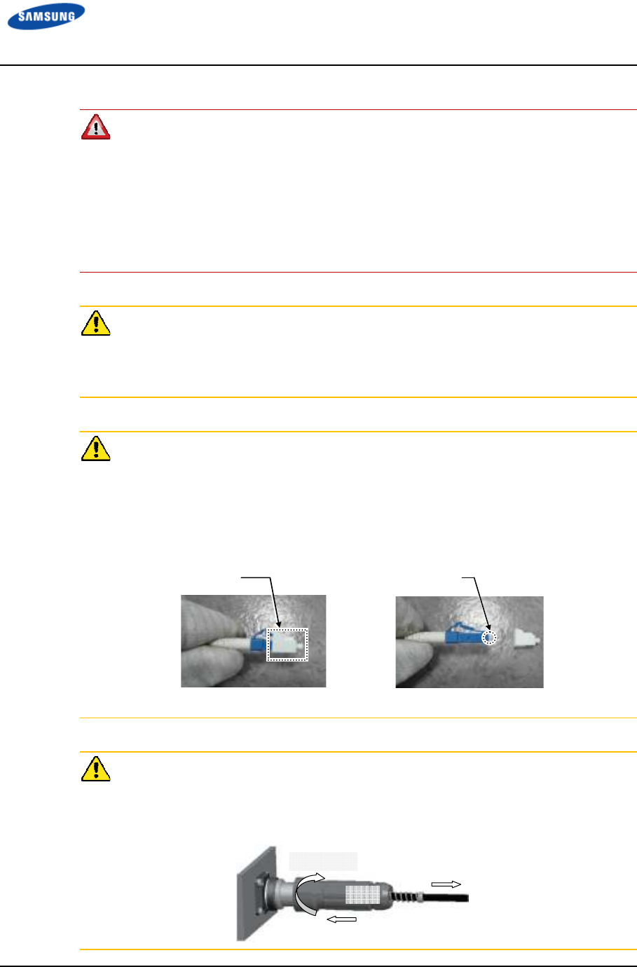
Error! Use the Home tab to apply 제목 1 to the text that you want to appear here.
Error! Use the Home tab to apply 제목 1 to the text that you want to appear here.
LTE TDD Outdoor Pico eNB Installation Manual v1.0 50
©Samsung Proprietary and Confidential
To prevent foreign substances, outdoor air and moisture from entering the system
input/output port and cable inlet (including cable gland and conduit), finish it as
follows:
- Unused inlet
Use the hole finishing materials including waterproof cap and rubber packing.
- Cable-installed Port and Cable Inlet
After cable installation, block any space in the inlet with tape, compressed sponge,
rubber packing, and silicon.
Caution for Laser Beam of Optical Module and Cable
The optical module and cable used in the system emit bright laser beams.
Always handle them with care as there is risk of serious injury if the eyes are
exposed to the laser beam of the optical cable.
Caution for Optic Cable Connection
1) After removing dust cap of optic cables, use optic cables.
2) Before connecting the optic connector, make sure that the connector is cleaned.
If there is any dust or foreign substance when cleaning the connector, do not
remove it by blowing with your mouth. Remove the dust or foreign substance by
referring to the cleaning instructions in ANNEX E.
3) Don't touch ferrule of optic cables because it is weak.
Precautions for connecting the optical cable connector are as follows:
- Do not assemble the optical cable while pushing it toward the system.
- After putting the cable in a straight line, pull the cable toward the arrow
direction slightly with one hand and fix the coupling nut with the other hand.
Dust Cap Ferrule
[Before removing Dust Cap] [After removing Dust Cap]
Cable
Shell
Coupling Nut
Error! Use the Home tab to apply 제목 1 to the text that you want to appear here.
Error! Use the Home tab to apply 제목 1 to the text that you want to appear here.
LTE TDD Outdoor Pico eNB Installation Manual v1.0 51
©Samsung Proprietary and Confidential
Figure 27. Backhaul Cable Connection–Optic Type(1)
Site Aggregation
Router
1) Install a backhaul cable from the Site Aggregation Router to the backhaul port (BH_OPT) of the
Outdoor Pico eNB.
2) Remove the dust cap in the 2LC plug of the backhaul cable.
[Outdoor Pico eNB]
Backhaul Cable (Optic, Outdoor Type)
3) Connect the 2LC plug on the side of the backhaul cable to the SFP module of the BH-OPT port on the
side of the Outdoor Pico eNB.
At the time, after inserting the 2LC plug latch upturned, check the ‘click’ sound.
Backhaul Cable
(
Optic
)
BH-OPT Port
2LC Plug
Fixing Tube
Latch Latch
Error! Use the Home tab to apply 제목 1 to the text that you want to appear here.
Error! Use the Home tab to apply 제목 1 to the text that you want to appear here.
LTE TDD Outdoor Pico eNB Installation Manual v1.0 52
©Samsung Proprietary and Confidential
Figure 28. Backhaul Cable Connection–Optic Type(2)
4) Align the fixing tube to the grooves of the BH-OPT connector on the Outdoor Pico eNB and insert it.
5) Push up the shell to the BH-OPT connector on the side of the Outdoor Pico eNB.
6) After putting the cable in a straight line, pull the cable toward the arrow direction slightly with one hand
and fix the coupling nut on the top of the shell with the other hand.
Shell
Backhaul Optic Cable
Coupling Nut
Error! Use the Home tab to apply 제목 1 to the text that you want to appear here.
Error! Use the Home tab to apply 제목 1 to the text that you want to appear here.
LTE TDD Outdoor Pico eNB Installation Manual v1.0 53
©Samsung Proprietary and Confidential
External Interface Construction
Backhaul Cable Connection (Copper Type)
Use the following tables and figures to connect the backhaul cable (copper type) to
the Outdoor Pico eNB.
The optic type and copper type have different parts and installation methods.
Prepare installation after checking the type with the service provider.
Table 25. Backhaul Cable Connection (Copper Type)
Category
CategoryCategory
Category
Description
DescriptionDescription
Description
Installation Section Outdoor Pico eNB BH-ETH0 Port ~ Site Aggregation Router
Cable S-FTP, Cat5e or Cat.6, 4 Pair
Connector Site Aggregation Router Checking Site Aggregation Router
side connector specifications and
preparing connecting parts
Outdoor Pico eNB RJ-45(Shield Type)
Working Tools LAN Tool, LAN Cable Tester, Nipper, Wire Stripper, Cable Cutter
Table 26. Backhaul Cable (Copper Type)/Connector Pin Map
Pin No.
Pin No.Pin No.
Pin No.
Description
DescriptionDescription
Description
Color
ColorColor
Color
1 Gigabit Ethernet Tx/Rx0+ White/Orange
2 Gigabit Ethernet Tx/Rx0- Orange
3 Gigabit Ethernet Tx/Rx1+ White/Green
4 Gigabit Ethernet Tx/Rx2+ Blue
5 Gigabit Ethernet Tx/Rx2- White/Blue
6 Gigabit Ethernet Tx/Rx1- Green
7 Gigabit Ethernet Tx/Rx3+ White/Brown
8 Gigabit Ethernet Tx/Rx3- Brown
Shell Shield Shield
Error! Use the Home tab to apply 제목 1 to the text that you want to appear here.
Error! Use the Home tab to apply 제목 1 to the text that you want to appear here.
LTE TDD Outdoor Pico eNB Installation Manual v1.0 54
©Samsung Proprietary and Confidential
The pin map provided by this manual is based on the connectors on the system
side. Check the pin connection positions when connecting to the cable side.
To prevent foreign substances, outdoor air, and moisture from entering the system
input/output port and cable inlet (including cable gland and conduit), finish it as
follows:
- Unused inlet
Use the hole finishing materials including waterproof cap and rubber packing.
- Cable-installed port and cable inlet
After cable installation, block any space in the inlet with tape, compressed sponge,
rubber packing, and silicon.
To connect an RJ-45 connector to a cable, refer to ‘Appendix D Connector
Assembly.
Error! Use the Home tab to apply 제목 1 to the text that you want to appear here.
Error! Use the Home tab to apply 제목 1 to the text that you want to appear here.
LTE TDD Outdoor Pico eNB Installation Manual v1.0 55
©Samsung Proprietary and Confidential
Figure 29. Backhaul Cable Connection–Copper Type(1)
Site Aggregation
Router
1) Install a backhaul cable from the Site Aggregation Router to the backhaul port (BH_ETH) of the
Outdoor Pico eNB.
2) Connect the connector of a backhaul cable to the backhaul port (BH_ETH) of the Outdoor Pico eNB.
At the time, after inserting the RJ-45 plug latch downturned, check the ‘click’ sound.
Backhaul Cable (Copper)
[Outdoor Pico eNB]
Fixing Tube
RJ-45 Plug
Latch
Error! Use the Home tab to apply 제목 1 to the text that you want to appear here.
Error! Use the Home tab to apply 제목 1 to the text that you want to appear here.
LTE TDD Outdoor Pico eNB Installation Manual v1.0 56
©Samsung Proprietary and Confidential
Figure 30. Backhaul Cable Connection–Copper Type(2)
3) Align the fixing tube to the grooves of the BH-ETH connector on the Outdoor Pico eNB and insert it.
4) Push up the shell to the BH-ETH connector on the side of the Outdoor Pico eNB.
5) After putting the cable in a straight line, pull the cable toward the arrow direction slightly with one hand
and fix the coupling nut on the top of the shell with the other hand.
Fixing Tube
Backhaul Cable (Copper)
Coupling Nut
Shell
Error! Use the Home tab to apply 제목 1 to the text that you want to appear here.
Error! Use the Home tab to apply 제목 1 to the text that you want to appear here.
LTE TDD Outdoor Pico eNB Installation Manual v1.0 57
©Samsung Proprietary and Confidential
GPS Cable Connection
Use the following tables and figures to connect the GPS cable.
Table 27. GPS Cable Connection
Category
CategoryCategory
Category
Description
DescriptionDescription
Description
Installation Section Outdoor Pico eNB - GPS Antenna
Cable 1/2 in. Coaxial Cable
Connector Outdoor Pico eNB N Type-Male
GPS arrestor N Type-Male
GPS Antenna N Type-Male
Recommended
Torque Value
N Type-Male 1.45 lbfft (20 kgfcm)
Working Tools Cable Cutter, Wire Stripper, Nipper, Torque Wrench, Spanner, Knife, Soldering Iron,
Lead
Table 28. GPS Cable Min. Radius of Curvature and Length Limitation
Category
CategoryCategory
Category
Description
DescriptionDescription
Description
GPS cable min. radius
of curvature
1/2 in. Coaxial Cable Installation 2 in. (50.8mm)
Repeated 5 in. (127 mm)
Length limitation of
GPS cable
Total length 1/2in. Coaxial Cable 32.8ft(10m or less)
When using GPS arrestor (Polyphaser, Part no.: DGXZ+06NFNF-A) and GPS antenna (PCTEL, GPS-
TMG-HR-26N’).
If the GPS cable minimum radius of curvature or its length limitation is violated, a
GPS signal may not be received seamlessly and it may cause abnormal system
operation. Therefore, the minimum radius of curvature and length limitation of a
GPS cable specified in Table 28. GPS Cable Min. Radius of Curvature and Length
Limitation must be observed.
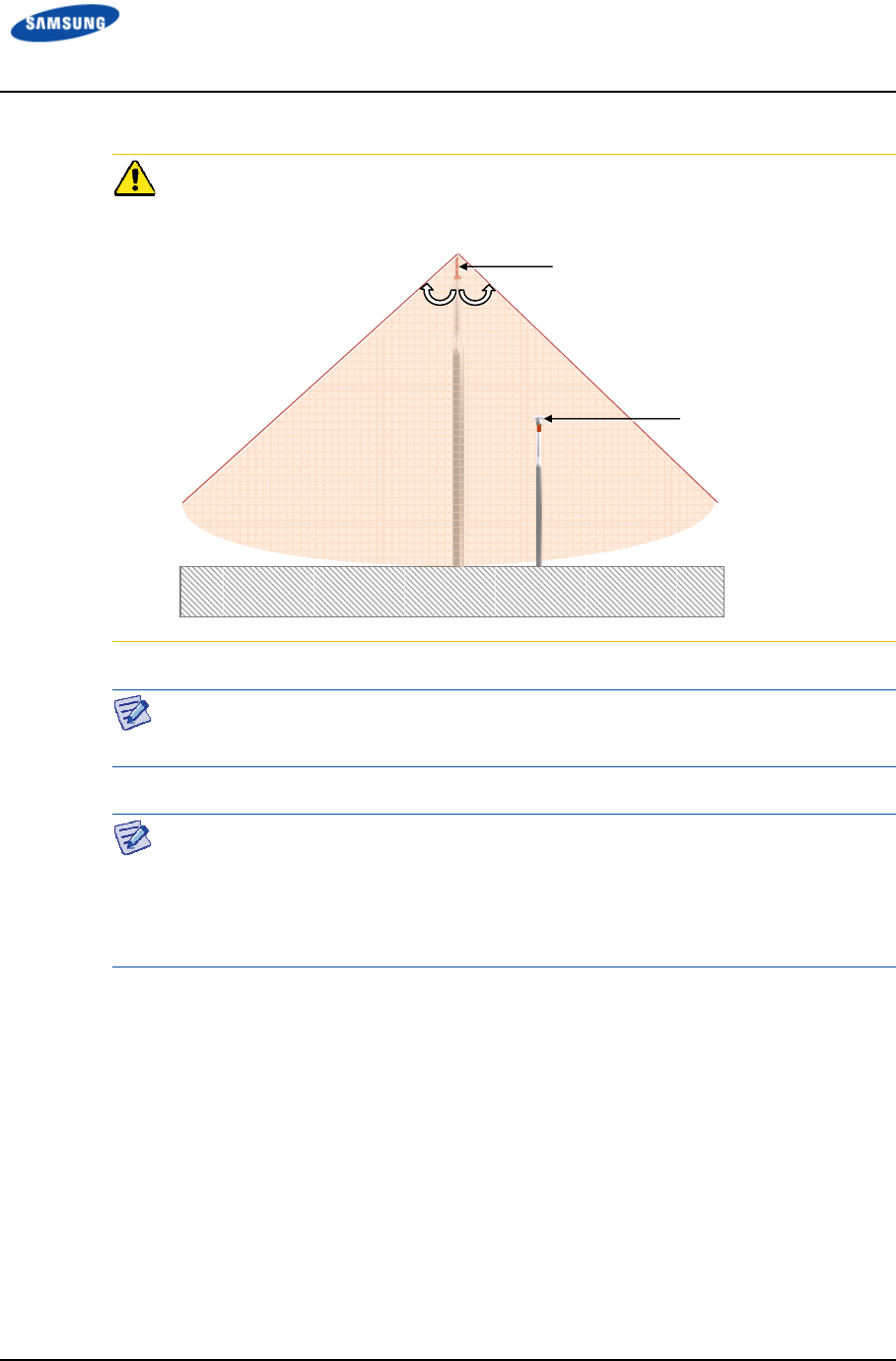
Error! Use the Home tab to apply 제목 1 to the text that you want to appear here.
Error! Use the Home tab to apply 제목 1 to the text that you want to appear here.
LTE TDD Outdoor Pico eNB Installation Manual v1.0 58
©Samsung Proprietary and Confidential
When you install the antenna, the antenna must be within the protective angle
(left/right side 45° each from the central axis) to protect the antenna from lightning
damage.
When installing the GPS antenna, you must check the antenna installation location,
restrictions, and installing method in ‘Appendix A GPS Antenna Installation’.
Depending on the supplier or manufacturer of the antenna/line amplifier the
connector type may be different. Also, the detail specifications of a connector may
be different depending on cable type even for the same connector type.
Therefore, check the detail specifications of a connector before preparing parts.
For example, N Type-Male: for 1/2 in. Coaxial Cable, for RG-316D
Lightning Rod
GPS Antenna
45°
45°
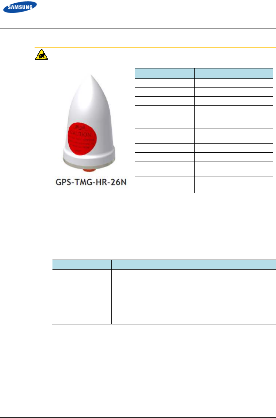
Error! Use the Home tab to apply 제목 1 to the text that you want to appear here.
Error! Use the Home tab to apply 제목 1 to the text that you want to appear here.
LTE TDD Outdoor Pico eNB Installation Manual v1.0 59
©Samsung Proprietary and Confidential
For GPS antenna, ‘PCTEL, GPS-TMG-HR-26N’ or equivalent must be used.
GPS Cable Identification Tag Installation
Attach the identification tape specified in Table 29. Identification Tag of GPS
Cable to the GPS cable.
Table 29. Identification Tag of GPS Cable
Classification
ClassificationClassification
Classification
Description
DescriptionDescription
Description
Installation position Attach the identification tag to the ends of the GPS antenna and
arrestor.
Materials Use aluminum coated by vinyl for the identification tag.
Fixing method Fix the GPS cable to the 2 holes on the identification tag with the
black cable tie.
Identification method Prevent the markings from being erased by using relief engraving
or coated labels.
Parameters
ParametersParameters
Parameters
Specifications
SpecificationsSpecifications
Specifications
Frequency Band 1575.42 ± 1.2 MHz
Amplifier Gain 26.5 ± 3 dB
Output VSWR ≤ 2.0:1
Noise Figure
(including pre-
selector)
≤ 4.0 dB @ +25°C (typ.)
≤ 4.5 dB @ +25°C (max.)
Operating DC
Voltage
3.3~12.0 V (regulated)
Survival DC Voltage 24 V
DC Current ≤ 40 mA @ 5 V
Filtering 4-stage filtering including
pre-selector
Out of Band
Rejection
≥ 65 dB @ 1559 MHz
≥ 65 dB @ 1625 MHz
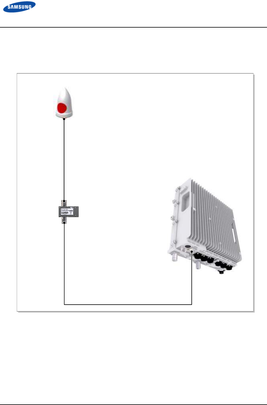
Error! Use the Home tab to apply 제목 1 to the text that you want to appear here.
Error! Use the Home tab to apply 제목 1 to the text that you want to appear here.
LTE TDD Outdoor Pico eNB Installation Manual v1.0 60
©Samsung Proprietary and Confidential
GPS Cable Configuration
The configuration of GPS cable is shown in Figure 31. GPS Cable Configuration.
Figure 31. GPS Cable Configuration
1/2 in. Coaxial Cable (LDF4-50A or equivalent)
[GPS Antenna]
[Outdoor Pico eNB]
[GPS Arrestor]
1/2 in Coaxial cable
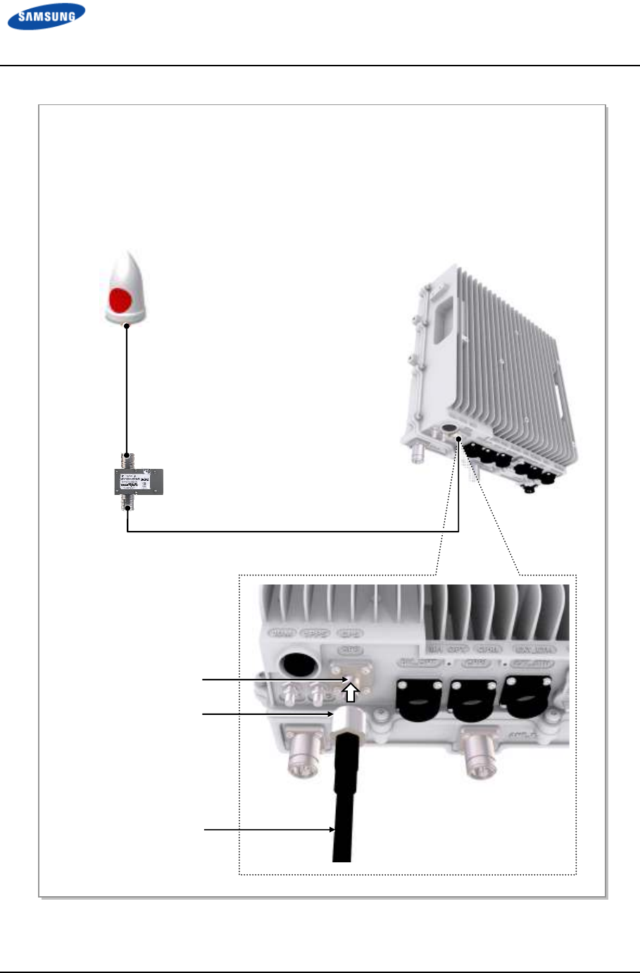
Error! Use the Home tab to apply 제목 1 to the text that you want to appear here.
Error! Use the Home tab to apply 제목 1 to the text that you want to appear here.
LTE TDD Outdoor Pico eNB Installation Manual v1.0 61
©Samsung Proprietary and Confidential
Figure 32. GPS Cable Connection (1)
[GPS Antenna]
1) Worker shall install a GPS cable (LDF4-50A) from the GPS port of the Outdoor Pico eNB to the GPS
antenna.
2) Worker shall assemble the connector to the GPS cable.
- Outdoor Pico eNB-side Connector: N Type-Male
- GPS Antenna-side Connector: N Type-Male
3) Worker shall connect the N Type-Male connector assembled to the end of the GPS cable to the GPS
port of the Outdoor Pico eNB.
1/2 in. Coaxial Cable (LDF4-50A or equivalent)
[Outdoor Pico eNB]
N Type-
Male Connector
GPS Port
[GPS Arrestor]
1/2 in. Coaxial cable
GPS Cable
(1/2 in. Coaxial Cable)
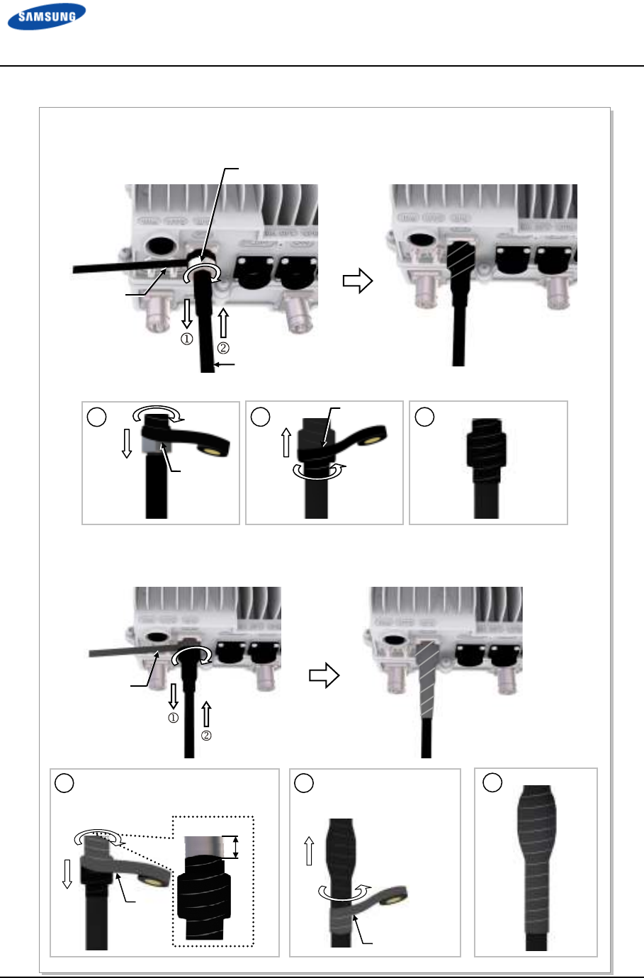
Error! Use the Home tab to apply 제목 1 to the text that you want to appear here.
Error! Use the Home tab to apply 제목 1 to the text that you want to appear here.
LTE TDD Outdoor Pico eNB Installation Manual v1.0 62
©Samsung Proprietary and Confidential
Figure 33. GPS Cable Connection (2)
4) Once the connector is connected and torqued to specification, wrap insulation tape around the
connector twice or more off the bottom to the system-side connector.
2
3
Insulation
Tape
1
Insulation
Tape
5) Wrap butyl tape around the cables more than twice over the wrapped insulation tape.
2
Butyl
Tape
1
Butyl Tape
10~20
mm
Start wrapping from the 10~20 mm
higher than the insulation tape
wrapped.
Wrap to 10~20 mm lower
than the end of insulation
tape.
3
N Type-Male Connector
Insulation
Tape
1/2 in. Coaxial Cable
Butyl
Tape
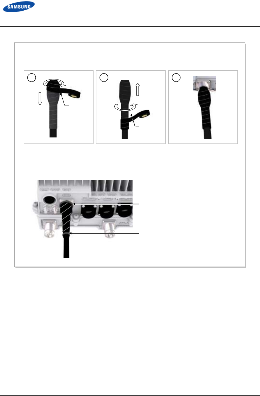
Error! Use the Home tab to apply 제목 1 to the text that you want to appear here.
Error! Use the Home tab to apply 제목 1 to the text that you want to appear here.
LTE TDD Outdoor Pico eNB Installation Manual v1.0 63
©Samsung Proprietary and Confidential
Figure 34. GPS Cable Connection (3)
6) Wrap the butyl taping section with insulation tape twice or more in the same way as for the butyl tape.
Cable Tie
7) Bind the end of the insulation tape with a cable tie or apply bond or silicone to prevent it from
loosening.
2
3
1
Cable Tie
Insulation
Tape
Insulation
Tape
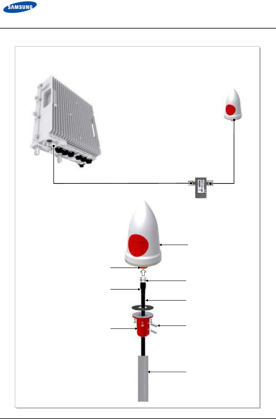
Error! Use the Home tab to apply 제목 1 to the text that you want to appear here.
Error! Use the Home tab to apply 제목 1 to the text that you want to appear here.
LTE TDD Outdoor Pico eNB Installation Manual v1.0 64
©Samsung Proprietary and Confidential
Figure 35. GPS Cable Connection (4)
8) Connect the 1/2 in. Coaxial Cable assembled with the N Type-Male connector to the GPS Arrestor port.
9) Connect the N Type-Male connector (assembled to the end of GPS cable) to the GPS antenna port.
1/2 in. Coaxial Cable (LDF4-50A or equivalent)
[GPS Antenna]
1/2 in. Coaxial Cable
GPS Antenna
N Type-Female Port
Clamp
Heat Shrink Tube (Jelly Type)
Clamp Fixing Screw
GPS Antenna Fixing Pipe
N Type-Male Connector
[GPS Arrestor]
1/2 in. Coaxial cable
[Outdoor Pico eNB]
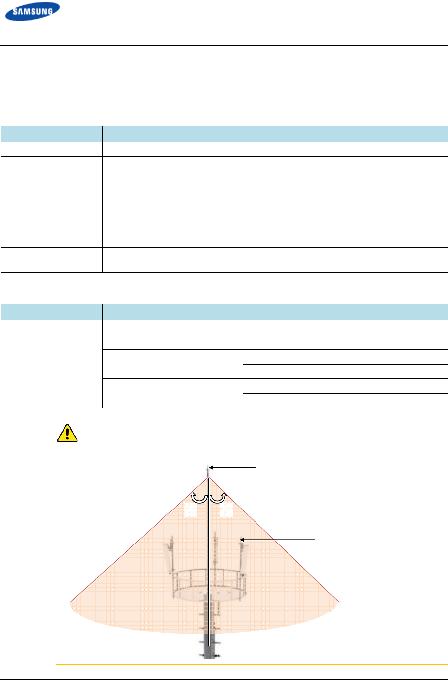
Error! Use the Home tab to apply 제목 1 to the text that you want to appear here.
Error! Use the Home tab to apply 제목 1 to the text that you want to appear here.
LTE TDD Outdoor Pico eNB Installation Manual v1.0 65
©Samsung Proprietary and Confidential
RF Cable Connection
Use the following tables and figures to connect the RF cable.
Table 30. RF Cable Connection
Category
CategoryCategory
Category
Description
DescriptionDescription
Description
Installation Section Outdoor Pico eNB RF Antenna Port (ANT) ~ RF Antenna
Cable 1/2 in. Feeder Line
Connector Outdoor Pico eNB Mini DIN Type-Male
RF Antenna Mini DIN Type-Male
(Check RF antenna specifications and prepare
connector)
Recommended
Torque Value
Mini DIN Type-Male 8 lbf·ft (110.4 kgf·cm)
Working Tools Cable Cutter, Wire Stripper, Nipper, Torque Wrench, Spanner, Knife, Soldering Iron,
Lead
Table 31. RF Cable Radius of Curvature (Min.)
Category
CategoryCategory
Category
Description
DescriptionDescription
Description
RF cable radius of
curvature (Min.)
1/2 in. Feeder Line (for Indoor) LS/HFSC-12D 32 mm
RFS/SCF-12-50 32 mm
1/2 in. Feeder Line (for Outdoor) LS/HFC-12D 125 mm
RFS/LCF12-50 125 mm
7/8 in. Feeder Line LS/HFC-22D 250 mm
RFS/LCF78-50 250 mm
When you install the antenna, it should be within the protective angle (left/right
side 45° each from the central axis) to protect it from lightning damage.
Lightning Rod
45°
45°
RF Antenna

Error! Use the Home tab to apply 제목 1 to the text that you want to appear here.
Error! Use the Home tab to apply 제목 1 to the text that you want to appear here.
LTE TDD Outdoor Pico eNB Installation Manual v1.0 66
©Samsung Proprietary and Confidential
Error! Use the Home tab to apply 제목 1 to the text that you want to appear here.
Error! Use the Home tab to apply 제목 1 to the text that you want to appear here.
LTE TDD Outdoor Pico eNB Installation Manual v1.0 67
©Samsung Proprietary and Confidential
Checking RF Cable Connection
After connecting the RF cables, perform the continuity test and feeder cable return
loss to check if it is changed. (Follow latest TS-200 Antenna Transmission Line
Acceptance Standards.)
Measure VSWR of antenna and RF cable.
Measure all the section of the cable ~ . The measured VSWR should be the
specification value or less. If the VSWR exceeds the specification value,
disassemble the connector and measure each section separately.
If the VSWR value for the minimum cable bend radius and length of RF cable is
not applied, the system may not work properly because the RF signals cannot
transmit or receive smoothly. Check and apply the VSWR value for minimum
cable bend radius and length of RF cable.
When measuring VSWR, if you open the antenna port when the transmission
output is not completely off, a spike signal may flow into the reception path. This
may cause damage to LNA. Make sure the transmission output is completely off
when measuring VSWR.
If you install the feeder line which is connected to the system, it may damage the
system and the cable connection. Therefore, install the feeder line to the system's
input port before connecting it to the system.
Depending on the supplier or manufacturer of the antenna, the connector type may
be different. Also, the detail specifications of a connector may be different
depending on cable type even for the same connector type.
Check the detail specifications of a connector before preparing parts.
For example, Mini Din Type-Male: for 1/2 in. Feeder line, for 7/8 in. Feeder Line
As different connector types may be used depending on the RF antenna type,
check the antenna connector before connecting the cable.
Connection Part of System External
Interface Connector
Antenna
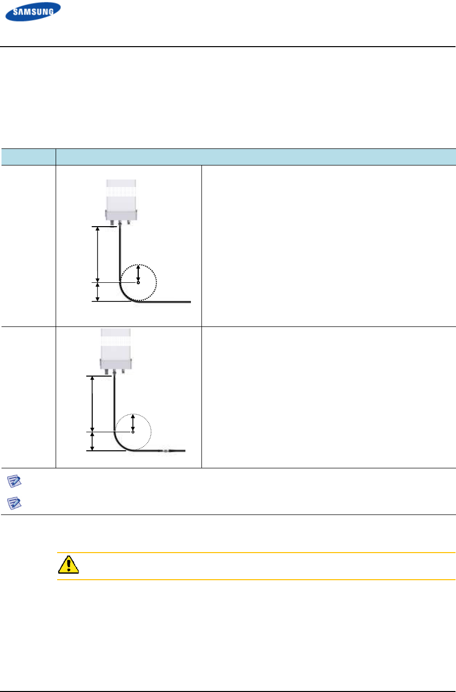
Error! Use the Home tab to apply 제목 1 to the text that you want to appear here.
Error! Use the Home tab to apply 제목 1 to the text that you want to appear here.
LTE TDD Outdoor Pico eNB Installation Manual v1.0 68
©Samsung Proprietary and Confidential
RF Cable Configuration
The RF cable is connected by the following methods shown in Table 32. RF Cable
Connection at Antenna Connection Area. Prepare and install parts based on the
method agreed by the service provider based on the site conditions.
Table 32. RF Cable Connection at Antenna Connection Area
Case
CaseCase
Case
Description
DescriptionDescription
Description
Case #1
Connect a 7/8 in. or longer feeder line directly to the RF
antenna.
• Space for minimum radius of curvature can be secured
when a 7/8 in. or larger feeder line is used.
• No excessive force is applied to the connector assembled
to the antenna port or cable because the straight cable
section is long enough.
Case #2
Connect a 1/2 in. feeder line (jumper cable) to the RF
antenna.
• Space for minimum radius of curvature cannot be secured
when a 1/2 in. feeder line is used.
• Excessive force is applied to the connector assembled to
the antenna port or cable and it may cause poor contact or
damage because the straight cable section is not long
enough.
7/8 in. or longer feeder line: 7/8 in., 1 1/4 in., 1 5/8 in. feeder line, and so on.
The RF cable should be connected based on the method agreed by the provider or the site conditions.
The RF cable minimum radius of curvature must be observed.
Straight cable
section
Min. radius
of curvature
R’
RF Antenna
Straight cable
section
Min. radius
of curvature
R’
RF Antenna

Error! Use the Home tab to apply 제목 1 to the text that you want to appear here.
Error! Use the Home tab to apply 제목 1 to the text that you want to appear here.
LTE TDD Outdoor Pico eNB Installation Manual v1.0 69
©Samsung Proprietary and Confidential
RF Cable Identification Tag Installation
Refer to Table 33. RF Cable Identification Tag for information on the cable
identification tag installation. (Refer to TS-200 Antenna Transmission Line
Acceptance Standards for Sprint cable marking requirements.)
Table 33. RF Cable Identification Tag
Category
CategoryCategory
Category
Description
DescriptionDescription
Description
Installation Position Attach the identification tag to both ends of the antenna.
Materials Use aluminum coated by vinyl for the identification tag.
Fixing Method • Antenna side: Attach the tag to the feeder line using binding strings through the
two holes on the tag.
• Equipment side: Cover the feeder line with the tag and fix it using binding strings
through the two holes on the tag.
Identification Method Use relief engraving or coated labels to prevent the markings from being erased.
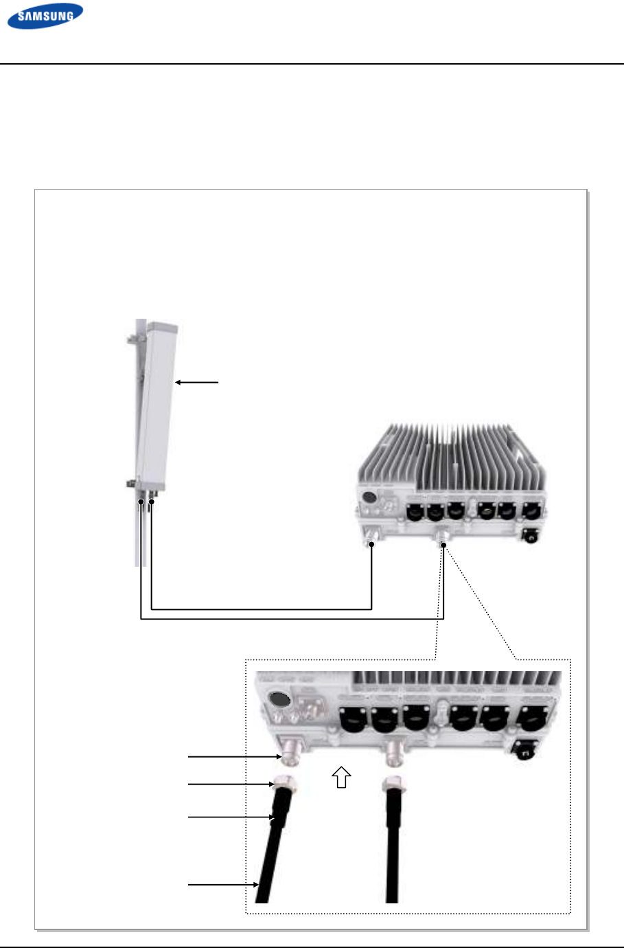
Error! Use the Home tab to apply 제목 1 to the text that you want to appear here.
Error! Use the Home tab to apply 제목 1 to the text that you want to appear here.
LTE TDD Outdoor Pico eNB Installation Manual v1.0 70
©Samsung Proprietary and Confidential
RF Cable Connection
Use the following figures to connect the cable between the Outdoor Pico eNB and
the RF antenna.
Figure 36. RF Cable Connection (1)
RF Antenna
RF Cable (1/2 in. Feeder Line)
Mini DIN Type-
Male
Connector
RF Cable
RF Antenna Port
Heat Shrink Tube
1) Worker shall connect the connectors to the RF ports (Mini DIN Type-Female) at the bottom of the
Outdoor Pico eNB.
2) Worker shall assemble the connector at the end of the RF cable. (The specifications of the antenna,
supplier-specific connector, and the tightening method are subject to change.)
- Outdoor Pico eNB Side Connector: Mini DIN Type-Male
- RF Antenna Side Connector: Mini DIN Type-Male
3) Connect the connector which is assembled at the end of the RF cable (Outdoor Pico eNB-side) to the
RF antenna port of the Outdoor Pico eNB.
[Outdoor Pico eNB]
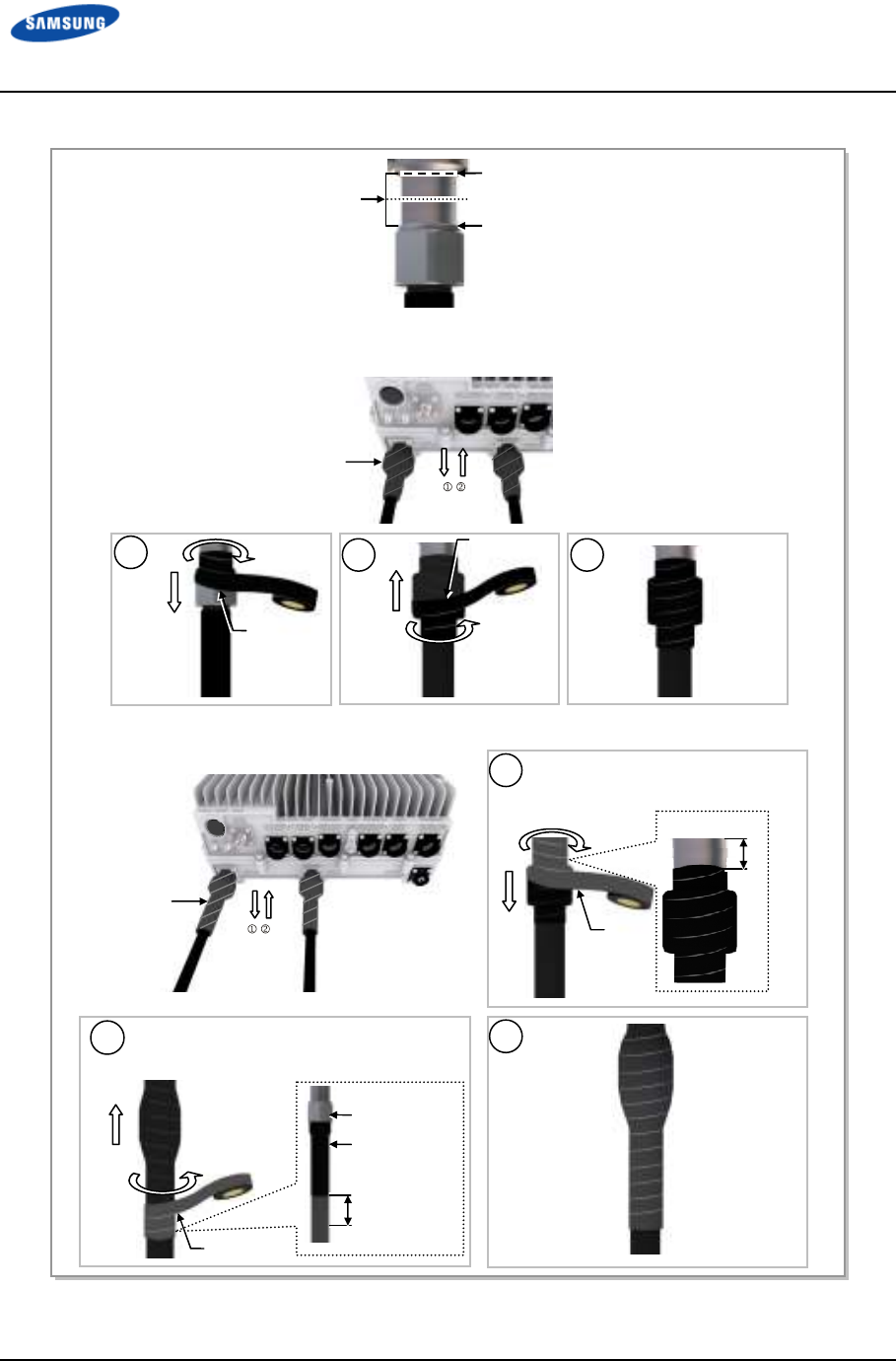
Error! Use the Home tab to apply 제목 1 to the text that you want to appear here.
Error! Use the Home tab to apply 제목 1 to the text that you want to appear here.
LTE TDD Outdoor Pico eNB Installation Manual v1.0 71
©Samsung Proprietary and Confidential
Figure 37. RF Cable Connection (2)
(1) Start and End points of Butyl Tape
Start and End points of
Insulation Tape
[Mid-point between (1) and (2)]
(2) Top side of Connector Nut
4) After connecting a connector, wrap the cable from the system-side connector using insulation tape more
than twice so that the metal part of the connector is completely protected, as shown: or install the customer
approved boot solution
5) Wrap butyl tape around the cables more than twice over the wrapped insulation tape.
Butyl Tape
2
3
Insulation
Tape
1
Insulation
Tape
2
Butyl
Tape
1
Butyl Tape
10~20
mm
Start wrapping from 10~20 mm
above
the insulation tape wrapped.
Wrap to 10~20 mm lower than the end of heat
shrink tube for the connector nut.
Heat Shrink
Tube
Connector Nut
3
10~20 mm
Insulation Tape
Error! Use the Home tab to apply 제목 1 to the text that you want to appear here.
Error! Use the Home tab to apply 제목 1 to the text that you want to appear here.
LTE TDD Outdoor Pico eNB Installation Manual v1.0 72
©Samsung Proprietary and Confidential
Figure 38. RF Cable Connection (3)
6) Wrap insulation tape around the cable more than twice over the wrapped butyl tape.
2
3
Insulation
Tape
1
7) Bind cable ties at the both ends of the insulation tape to prevent it from loosening.
Insulation
Tape
Cable Tie
Insulation Tape
Error! Use the Home tab to apply 제목 1 to the text that you want to appear here.
Error! Use the Home tab to apply 제목 1 to the text that you want to appear here.
LTE TDD Outdoor Pico eNB Installation Manual v1.0 73
©Samsung Proprietary and Confidential
Figure 39. RF Cable Connection (4)
RF Antenna
8) Connect the connector (assembled to the end of the cable on the RF antenna side) to the RF antenna
port.
RF Antenna Input Port
Heat Shrink Tube (Jelly Type)
Mini DIN Type-Male Connector
RF Cable
9) After connecting a connector, wrap the cable from the system-side connector using insulation tape more
than twice so that the metal part of the connection does not show or install a customer approved weather
boot solution.
Insulation Tape
(1) Starting and Ending points of Butyl Tape
Starting and Ending points of
Insulation Tape
[Mid-point between (1) and (2)] (2) Top side of Connector Nut
2
3
Insulation
Tape
1
Insulation
Tape
Error! Use the Home tab to apply 제목 1 to the text that you want to appear here.
Error! Use the Home tab to apply 제목 1 to the text that you want to appear here.
LTE TDD Outdoor Pico eNB Installation Manual v1.0 74
©Samsung Proprietary and Confidential
Figure 40. RF Cable Connection (5)
RF Antenna
8) Connect the connector (assembled to the end of the cable on the RF antenna side) to the RF antenna
port.
RF Antenna Input Port
Heat Shrink Tube (Jelly Type)
Mini DIN Type-Male Connector
RF Cable
9) After connecting a connector, wrap the cable from the system-side connector using insulation tape more
than twice so that the metal part of the connection does not show or install a customer approved weather
boot solution.
Insulation Tape
(1) Starting and Ending points of Butyl Tape
Starting and Ending points of
Insulation Tape
[Mid-point between (1) and (2)] (2) Top side of Connector Nut
2
3
Insulation
Tape
1
Insulation
Tape
Butyl Tape
10) Wrap butyl tape around the cables more than twice over the wrapped insulation tape.
11) Wrap insulation tape around the cable more than twice over the wrapped butyl tape.
Insulation Tape
2
Butyl
Tape
1
Butyl Tape
10~20
mm
Start wrapping from the 10~20 mm
higher than the insulation tape
wrapped.
Wrap to 10~20 mm lower than the end of heat
shrink tube for the connector nut.
3
Heat shrink
tube
Connector Nut
10~20 mm
2
3
Insulation
Tape
1
Insulation
Tape
Error! Use the Home tab to apply 제목 1 to the text that you want to appear here.
Error! Use the Home tab to apply 제목 1 to the text that you want to appear here.
LTE TDD Outdoor Pico eNB Installation Manual v1.0 75
©Samsung Proprietary and Confidential
Figure 41. RF Cable Connection (6)
12) Bind cable ties at both ends of the insulation tape to prevent it from loosening.
Cable Tie
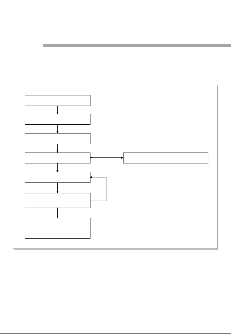
LTE TDD Outdoor Pico eNB Installation Manual v1.0 76
©Samsung Proprietary and Confidential
Chapter 4
Chapter 4Chapter 4
Chapter 4 Check
CheckCheck
Checking
inging
ing
Installation
Installation Installation
Installation
Status
StatusStatus
Status
Figure 42. Installation Checking Procedure shows the procedure to check
installation status.
Figure 42. Installation Checking Procedure
No
Yes
Sharing Inspection Results
Taking Corrective Actions
Checking the Results of
Corrective Actions
On-site Inspection
Inspection Checklist
Inspection Checklist/Corrective Actions
Sharing the Results of
Corrective Actions and
Preparing Preventive Plan
Inspection Plan

Error! Use the Home tab to apply 제목 1 to the text that you want to appear here.
Error! Use the Home tab to apply 제목 1 to the text that you want to appear here.
LTE TDD Outdoor Pico eNB Installation Manual v1.0 77
©Samsung Proprietary and Confidential
Inspection Plan
Create an inspection sheet as per the system and select an inspector to set an
inspection schedule as per site.
On-site Inspection and Inspection Checklist
The on-site inspection is to perform a visual inspection or inspect the site
using instruments for each specification, standard, and installation status based
on the checklist of the installation location.
The inspector must record the results into the inspection checklist during or
after completing filed inspection.
Share Inspection Result and Take Corrective Measures
The inspector must share the inspection result (inspection checklist/corrective
action) and the installation operator must take corrective actions if necessary
after reviewing all requirements.
Check the Result of Corrective Action
The inspector must verify if the corrective actions are properly taken. If they
are not sufficient, the inspector should ask the operator to take the proper
actions.
Share Corrective Measure Result and Prepare Preventive Plan
After the corrective actions are completed, the inspector should share the
results with the operator and relevant departments. The inspector should also
prepare a preventive plan to avoid any re-occurrence of such problems.
Table 34. Construction Situation Checklist
Category
CategoryCategory
Category
Check Items
Check ItemsCheck Items
Check Items
Criteria
CriteriaCriteria
Criteria
Result
ResultResult
Result
Pass
PassPass
Pass
Fail
FailFail
Fail
Installing
Equipment
Appearance of equipment and
mechanical parts
Checking for equipment damage such
as dents, scratches, and cracks.
Placement of equipment and
mechanical parts
Checking the maintenance and
horizontal/vertical placement
Leveling condition of equipment
and mechanical parts
Checking horizontal/vertical fixing
(level, weight, rubber hose, and so on)
Validity of status and
specifications of tightening
bolt/nut/washer, and so on.
Visually inspecting and magnet
checking
Checking compliance with tightening
torque value
Other works (cable duct
installation status, and so on)
Checking position and installation status

Error! Use the Home tab to apply 제목 1 to the text that you want to appear here.
Error! Use the Home tab to apply 제목 1 to the text that you want to appear here.
LTE TDD Outdoor Pico eNB Installation Manual v1.0 78
©Samsung Proprietary and Confidential
Category
CategoryCategory
Category
Check Items
Check ItemsCheck Items
Check Items
Criteria
CriteriaCriteria
Criteria
Result
ResultResult
Result
Pass
PassPass
Pass
Fail
FailFail
Fail
Grounding Status of ground bar installation
per usage
Checking the separation of
communication/power/lightning
grounding
Cable size Checking specifications such as
thickness, and so on.
Cabling and binding status Checking for cable damage/proper
installation route, binding interval, and
the condition of used materials
Cable connection Checking the assembly and tightening
condition of a pressure terminal
Checking compliance with tightening
torque value
Installation status of cable tag Checking position, marking, and tag
installation type
Power Installation status of power supply
and circuit breaker
Checking power supply capacity/input
voltage (tester)
Checking circuit breaker type and
capacity
Cable size Checking thickness and length limitation
Cabling and binding status Checking for cable damage/proper
installation route, binding interval, and
the condition of used materials
Cable connection Checking for cable damage/proper
installation route,
binding interval, and the condition of
used materials
Installation status of cable tag Checking position, marking, and tag
installation type
Other data
cables
Cable size Checking cable specifications per usage
Cabling and binding status Checking for cable damage/proper
installation route, binding distance, and
the condition of used materials
Cable connection Checking cable connection (pin map),
assembly and tightening status of a
connector, and compliance with
tightening torque value
Installation status of cable tag Checking position, marking, and tag
installation type
RF/GPS GPS signal reception status
(number of GPS reception
satellites)
Checking more than 6 reception
satellites (C/N 40 or higher)
Checking in-band or out-band jamming
Antenna installation status Checking specifications, installation
position, fixing status, and gap between
antennas
Installation status of arrestor/
line amplifier/ splitter, and so on
Checking specifications, installation
position, and fixing status
Cabling and binding status Checking for cable damage/proper
installation route, binding distance, and

Error! Use the Home tab to apply 제목 1 to the text that you want to appear here.
Error! Use the Home tab to apply 제목 1 to the text that you want to appear here.
LTE TDD Outdoor Pico eNB Installation Manual v1.0 79
©Samsung Proprietary and Confidential
Category
CategoryCategory
Category
Check Items
Check ItemsCheck Items
Check Items
Criteria
CriteriaCriteria
Criteria
Result
ResultResult
Result
Pass
PassPass
Pass
Fail
FailFail
Fail
the condition of used materials
Cable connection Checking cable connection status,
connector assembly and tightening
status, compliance with tightening
torque value, and finishing
Installation of cable tag Checking position, marking, and tag
installation type
Others Reserved ports and cable inlet
status
Finishing (waterproof cap, and so on)
Connection of equipment I/O port
(conduit/cable gland)
Checking tightening status
Installation of cable installation
route
Checking installation of cable tray and
duct.
Status of inside/outside of the
equipment and system
surrounding area
Checking the stocking condition of
waste parts, waste materials, packing
materials, and so on.
Opinion

LTE TDD Outdoor Pico eNB Installation Manual v1.0 80
©Samsung Proprietary and Confidential
Appendix A
Appendix A Appendix A
Appendix A Acronyms
AcronymsAcronyms
Acronyms
BPF Band Pass Filter
DL Downlink
EMC Electromagnetic Compatibility
FDD Frequency Division Duplex
FE Fast Ethernet
GE Gigabit Ethernet
GPS Global Positioning System
GPSR Global Positioning System Receiver
LNA LOW Noise Amplifier
LTE Long Term Evolution
MIMO Multiple Input Multiple Output
RF Radio Frequency
SIMO Single Input Multiple Output
UL Uplink
VSWR Voltage Standing Wave Ratio
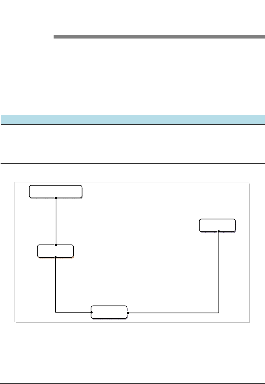
LTE TDD Outdoor Pico eNB Installation Manual v1.0 81
©Samsung Proprietary and Confidential
Appendix B
Appendix B Appendix B
Appendix B GPS Antenna
GPS Antenna GPS Antenna
GPS Antenna
Installation
InstallationInstallation
Installation
GPS Antenna System Configuration
The GPS antenna system is commonly configured as shown in Table 35. GPS
Antenna System Configuration and Figure 43. Example of a Common GPS
Antenna System Configuration.
Table 35. GPS Antenna System Configuration
Category
CategoryCategory
Category
Description
DescriptionDescription
Description
GPS Antenna Device receiving a signal from a GPS satellite
GPS Line amplifier (Option) Device amplifying the GPS signal received from the GPS antenna
(used to compensate the GPS signal loss caused by GPS antenna, GPS
arrestor, cable, and connector)
GPS (Lightning) Arrestor Device protecting people or system from lightning
Figure 43. Example of a Common GPS Antenna System Configuration
To satisfy the GPS specifications and operate the GPS antenna in a stable manner,
the following GPS antenna configuration and installation requirements must be
met.
GPS Arrestor
System
Line Amplifier
GPS Antenna
GPS Cable
GPS Cable GPS Cable
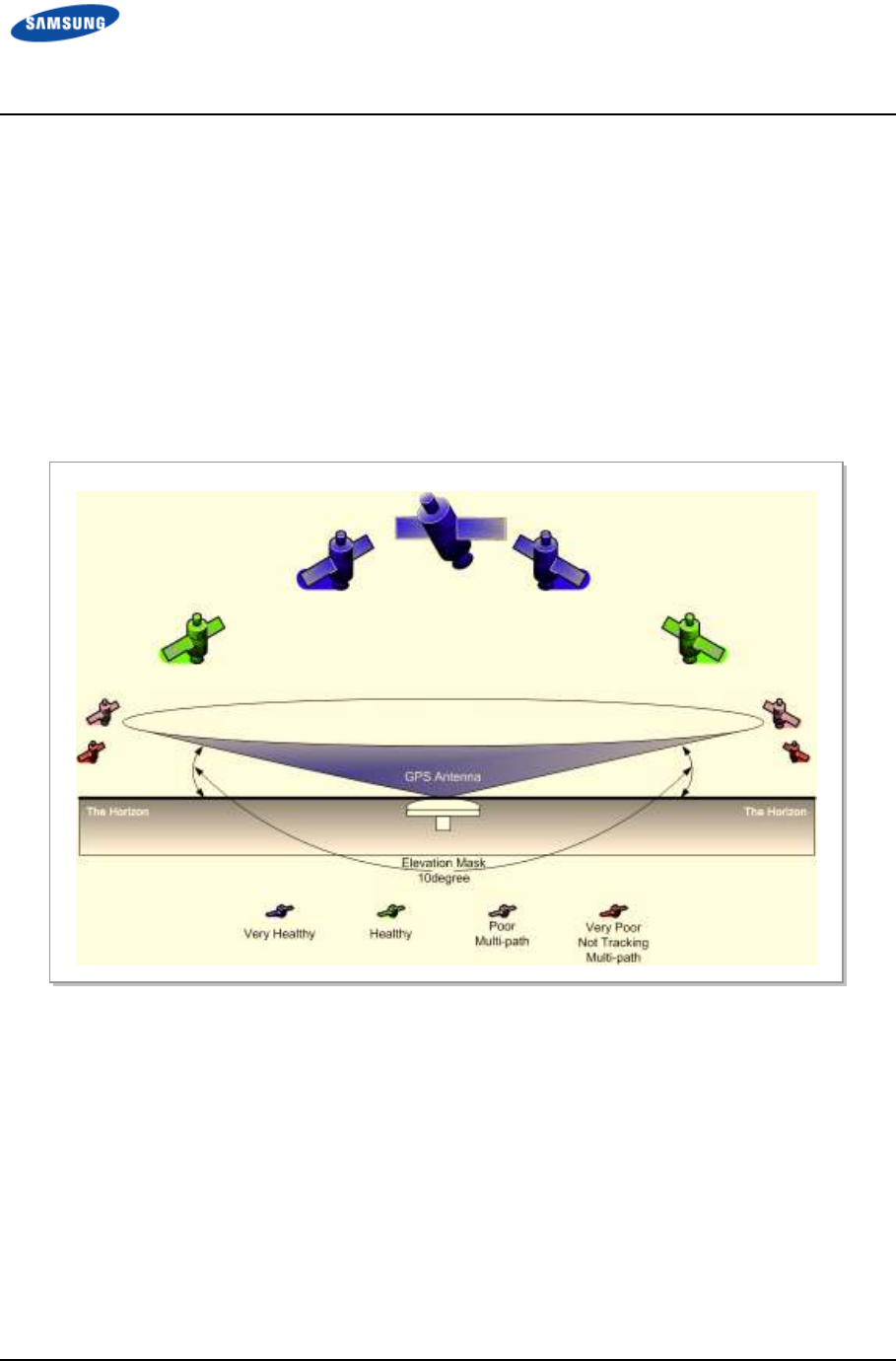
Error! Use the Home tab to apply 제목 8 to the text that
you want to appear here. Error! Use the Home tab to apply 제목 8 to the text that you want to
appear here.
LTE TDD Outdoor Pico eNB Installation Manual v1.0 82
©Samsung Proprietary and Confidential
GPS Antenna
Installation Requirements for the GPS Antenna
The GPS antenna must be installed in a location where it has the maximum
amount of open sky. The ideal position is one where there are no obstacles that
interfere with the antenna within 10 degrees or more of the horizon (the Elevation
Angle). This allows the GPS receiver to select the best combination or distribution
of GPS satellites which gives optimal performance. Refer to Figure 44. Elevation
Mask and Satellites.
Figure 44. Elevation Mask and Satellites
For good signal strength, it is not necessary to place the GPS antenna on a high
pole or building, which is often required for RFs and microwaves. It may be
installed any place where there are no obstacles blocking the GPS antenna from
the sky and where it is protected from the elements such as outside interference is
suitable. In this case, it can even be installed on the ground.
However, the GPS antenna may be preventedfrom malfunctioning by installing it
in a place where it does not receive reflected satellite signals. As multi-path
interference greatly affects the accuracy of the GPS receiver, it is better to
minimize reflected satellite signals entering through the top of the GPS antenna.
Error! Use the Home tab to apply 제목 8 to the text that
you want to appear here. Error! Use the Home tab to apply 제목 8 to the text that you want to
appear here.
LTE TDD Outdoor Pico eNB Installation Manual v1.0 83
©Samsung Proprietary and Confidential
Therefore, the GPS antenna installation location must meet the following
conditions.
• In a location that can avoid an obstacle/building that interferes with reception
of the GPS signal or causes multi-path
• In a location that can avoid interference of RF signal that is
transmitted/received at another RF antenna (including steel-framed structure
for RF antenna) or microwave signal
• In as low as possible location that avoids damage from lightning within
coverage area of a lightning rod
Considering the elevation mask, make the GPS antenna take the signals received at
a valid elevation angle only.
If a GPS antenna is influenced by external interference signals or multi-paths at
a certain place, it is best to install the antenna at another location. An anti-jamming
GPS antenna is recommended, if it is not possible to change the location of the
antenna.
GPS Antenna Sharing
A recommendation to ensure the GPS receiver works properly is to install one
GPS antenna per GPS receiver, and use a GPS-specific splitter only if necessary.
Installing the GPS Antenna
The signals from a GPS satellite have a very low level (-130 dBm). As a result, for
the GPS antenna to receive signals, its installation should be in a place where it
can receive them as direct as possible from as many satellites as possible.
Therefore, it is important to ensure that there is maximum open sky (the visual
field angle must be 360 degrees, and there must be 160 degrees or more above the
horizon). Any obstacle within those angles decreases the performance and
functionality of the GPS receiver.
The GPS satellites are distributed so that eight of them can always be tracked from
any one place around the world, as long as there is no obstacle to them in that
particular place.
For the GPS receiver to operate at its best there must be six GPS satellites always
with a healthy status (that is, there is no obstacle directly between it and the GPS
antenna).
If the position hold operation has been completed, the GPS receiver can only
perform its operations stably if at least one satellite can be tracked continually.

Error! Use the Home tab to apply 제목 8 to the text that
you want to appear here. Error! Use the Home tab to apply 제목 8 to the text that you want to
appear here.
LTE TDD Outdoor Pico eNB Installation Manual v1.0 84
©Samsung Proprietary and Confidential
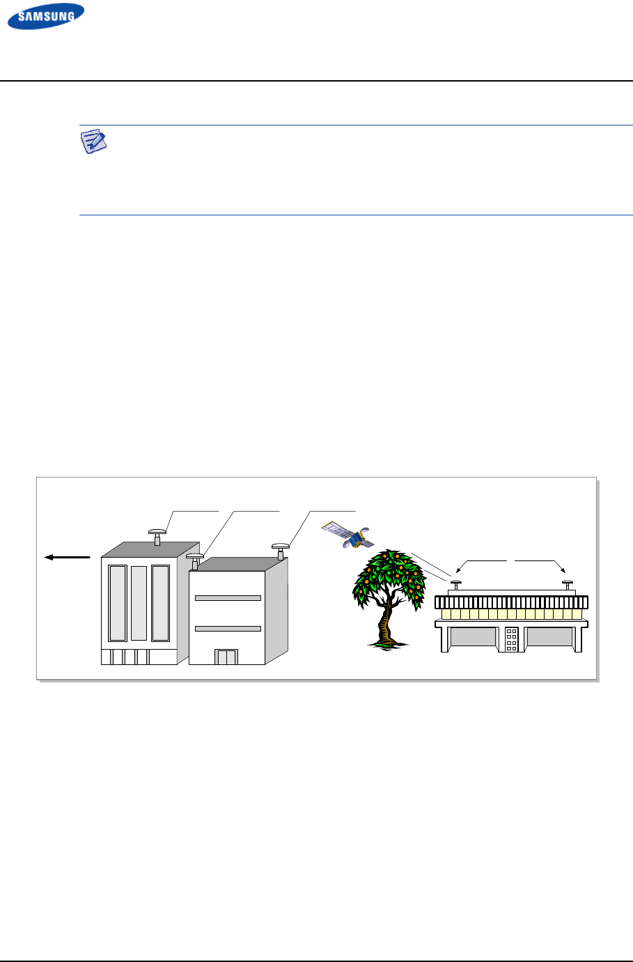
Error! Use the Home tab to apply 제목 8 to the text that
you want to appear here. Error! Use the Home tab to apply 제목 8 to the text that you want to
appear here.
LTE TDD Outdoor Pico eNB Installation Manual v1.0 85
©Samsung Proprietary and Confidential
The survey of an object’s position using GPS satellites is based on triangulation.
Three satellites are enough to survey the position of an object by triangulation.
However, to calculate the correct time deviation, a total of four satellites are
required.
Usually, the GPS antenna is installed in a high place, such as on a roof. It must be
installed away from protruding objects, such as trees or buildings. In addition, it
must be positioned away from any obstacle which covers part of the sky around
the horizon of the building where it is installed.
If it is impossible to ensure a completely open sky, install the GPS antenna facing
the equator providing a maximum view of the Southern sky in the Northern
hemisphere (or the Northern sky in the Southern hemisphere). Refer to Figure 45.
GPS Antenna Installation.
Furthermore, when installing the GPS antenna using a steel cylinder structure
shared by other RF antennas, the antenna must be separated by more than 1 m
from that steel structure.
Figure 45. GPS Antenna Installation
Lightening Arrestor
A lightning arrestor is required when there is a danger of lightning striking a cable
or related part. The lightning arrestor must be installed in a place where the
antenna cable or set of combined cables enters a building or station, or a place
inside the building or station in order to protect the people and equipment inside
the building or station.
If struck directly by lightning, the lightning arrestor, antenna, or cable must be
replaced. Furthermore, inspect the lightening arrestor periodically and replace the
antenna and cable periodically if lightning strikes occur frequently at the site.
The lightning arrestor must be well grounded so that it can transmit a large current
quickly.
Towards
Equator
Preferred
Position
Obstructed
Position
Improved
Visibility
Obstructed
position
Better
Position

Error! Use the Home tab to apply 제목 8 to the text that
you want to appear here. Error! Use the Home tab to apply 제목 8 to the text that you want to
appear here.
LTE TDD Outdoor Pico eNB Installation Manual v1.0 86
©Samsung Proprietary and Confidential

Error! Use the Home tab to apply 제목 8 to the text that
you want to appear here. Error! Use the Home tab to apply 제목 8 to the text that you want to
appear here.
LTE TDD Outdoor Pico eNB Installation Manual v1.0 87
©Samsung Proprietary and Confidential
Interference Signal
The GPS system is designed so that it has a strong immunity to noise and can
endure interference.
The Samsung GPS receiver provides a quality timing clock in most installations.
However, to ensure that the GPS receiver performs locking successfully and
guarantees uninterrupted timing performance, an interference-free environment is
required for frequencies near the GPS L1 frequency (1575.42 ± 1 MHz).
Interference Types
There are two types of interference which affect the GPS L1 frequency.
• Narrow band (inband) interference: When a frequency deviation (3.5 kHz),
such as an FM wave, inflows around the GPS L1 frequency (1575.42 MHz).
Narrow band interference is monitored by the spectrum analyzer. But because
it has a time lag, a locking failure or a different type of alarm can occur.
• Wideband interference: When frequency deviation is more than 7 kHz around
the GPS L1 frequency (1575.42 MHz).
Wideband interference includes the interference induced by the harmonics
from a communication service with a different frequency bandwidth, increased
thermal noise from communication services around the L1 band, inflow of
interference due to unauthorized communication, saturation due to oscillation
of an accessory device, and so on.
You cannot monitor these kinds of interference with a device such as a
spectrum analyzer. If the system has a wideband interference problem, you
should consult an expert in this area.
For bandwidths other than the GPS L1 frequency (1575.42 ± 1 MHz), a GPS Band
Pass Filter (BPF) must be included within the GPS antenna to remove the
interference from the GPS bandwidth. No outband interference must affect the
GPS signals.

Error! Use the Home tab to apply 제목 8 to the text that
you want to appear here. Error! Use the Home tab to apply 제목 8 to the text that you want to
appear here.
LTE TDD Outdoor Pico eNB Installation Manual v1.0 88
©Samsung Proprietary and Confidential
Avoiding Interference
If more than one antenna for other communications is installed in the surrounding
area, such as an antenna for a base station or satellite communication, the GPS
antenna must be installed in a location where no interference signals flow.
If interference exists within the GPS L1 frequency bandwidths (1575.42 ± 1
MHz), use a band pass filter (BPF) to prevent interference from affecting the GPS
bandwidth.
Furthermore, if the GPS antenna is installed by a transmitter which operates with a
bandwidth similar to the GPS L1 frequency, the possibility of interference
increases (in this case, interference is caused by harmonics). If the GPS antenna
has a problem due to interference, move it to a different location where
interference signals can be avoided or minimized.
Inband noise includes narrow band noise and wide band noise that occur in an
inband width. (L1, 1575.42 ± 1 MHz)
• Narrow band noise in an inband width: If it is higher than 108 dBm, it can
affect the operation of the GPS receiver.
• Wideband noise in an inband width: It may not be detected by a measuring
instrument and may impair the sensitivity of the GPS receiver, and thus affect
its operation.
If there is an outband interference problem, reduce the effects of interference on
the GPS receiver by applying one or more L1 GPS BPFs.
The filter should be installed at the following locations:
• The input connector of the Samsung GPS receiver
• Behind the antenna or the front end of a line amplifier
These filters are used to reject jamming tones for outband signals. If interferences
occur in the inband signals, they will result in serious consequences.
Error! Use the Home tab to apply 제목 8 to the text that
you want to appear here. Error! Use the Home tab to apply 제목 8 to the text that you want to
appear here.
LTE TDD Outdoor Pico eNB Installation Manual v1.0 89
©Samsung Proprietary and Confidential
GPS Antenna Installation
The GPS antenna can be fixed to a wall, floor, tower, or pole.
Ensure personal safety when fixing an anchor bolt to a wall and treat the anchor
bolt fixing area with a silicon or waterproof finishing material.
Install a concrete block that satisfies the specification regarding size and strength.
When installing the concrete block, and before forming the concrete, arrange steel
reinforcement bars in a mesh layout at 3.93 in. (100 mm) intervals. (Use either an
anchor bolt assembly or a concrete anchor.)
Install the antenna within the protective angle (left/right side 45° each from the
central axis) to protect the antenna from lightning damage.
Secure a distance of 3.28~4.92 ft (1~1.5 m) between the antennas to prevent
interference.
Lightning Rod
45°
45°
GPS Antenna
Error! Use the Home tab to apply 제목 8 to the text that
you want to appear here. Error! Use the Home tab to apply 제목 8 to the text that you want to
appear here.
LTE TDD Outdoor Pico eNB Installation Manual v1.0 90
©Samsung Proprietary and Confidential
Wall
Figure 46. GPS Antennal Installation (Wall)
GPS Antenna Wall Fixing Pipe
[Ф 1~1.46 in. (25~37 mm)]
GPS Antenna
GPS Antenna
Wall Fixing Clamp Assembly
≒
Min. 19.68 in. (500 mm)
Error! Use the Home tab to apply 제목 8 to the text that
you want to appear here. Error! Use the Home tab to apply 제목 8 to the text that you want to
appear here.
LTE TDD Outdoor Pico eNB Installation Manual v1.0 91
©Samsung Proprietary and Confidential
Floor
Figure 47. GPS Antennal Installation (Floor)
GPS Antenna Floor Fixing Pipe
[Ф 1~1.46 in. (25~37 mm)]
GPS Antenna
M10 Anchor Bolt Assembly
≒
Min. 19.69 in. (500 mm)
Concrete Block
≒ Min. 15.74 in. (400 mm)
≒
Min. 9.84 in. (250 mm)

LTE TDD Outdoor Pico eNB Installation Manual v1.0 92
©Samsung Proprietary and Confidential
Appendix C
Appendix C Appendix C
Appendix C Sector Antenna
Sector Antenna Sector Antenna
Sector Antenna
Installation
InstallationInstallation
Installation
Cautions when Installing a Sector Antenna
Precautions of antenna installation are as follows.
• Sector antennas should be installed vertically. (±1°)
• Antenna is the precise material, so be careful not to make damage or form
change.
• When moving antenna, use the tool suitable to rating. In addition, use the rated
carrying device which is at least 200 % or more than antenna considering the
stability.
• Be careful not to give too much strength to the antenna.
• If it rains, suspend connecting the feeder cable and antenna.
• Fix it after adjusting the direction of antenna exactly.
• Distance between steel tower and antenna and the distance between send-
receive antennas are based on the antenna layout.
• Attach the antenna on the position specified in the drawing.
• Install the antenna not to make a feature change of the antenna considering the
direction of the radiation
• Connect the antenna not making the alien substance flowed so that Passive
Inter-Modulation Distortion (PIMD) is not affected.
• Measure VSWR of all antennas and the value should be within the regulated
value.

Error! Use the Home tab to apply 제목 8 to the text that
you want to appear here. Error! Use the Home tab to apply 제목 8 to the text that you want to
appear here.
LTE TDD Outdoor Pico eNB Installation Manual v1.0 93
©Samsung Proprietary and Confidential
Sector Antenna Installation
The method of sector antenna installation is as follows.
1 Put up an antenna pole and insert the sector antenna into the antenna pole
using a fixing clamp.
2 Set the antenna’s up/down tilt to 0° and fix the fixing clamps at the top and
bottom.
3 Adjust the tilted angle of the antenna by taking the signal strength into
account. The bolts on the upper and lower guide clamps must be loose as to
allow angle adjustment of the antenna.
4 After adjusting the antenna angle, tighten up the 4 loose bolts on the upper and
lower guide clamps.
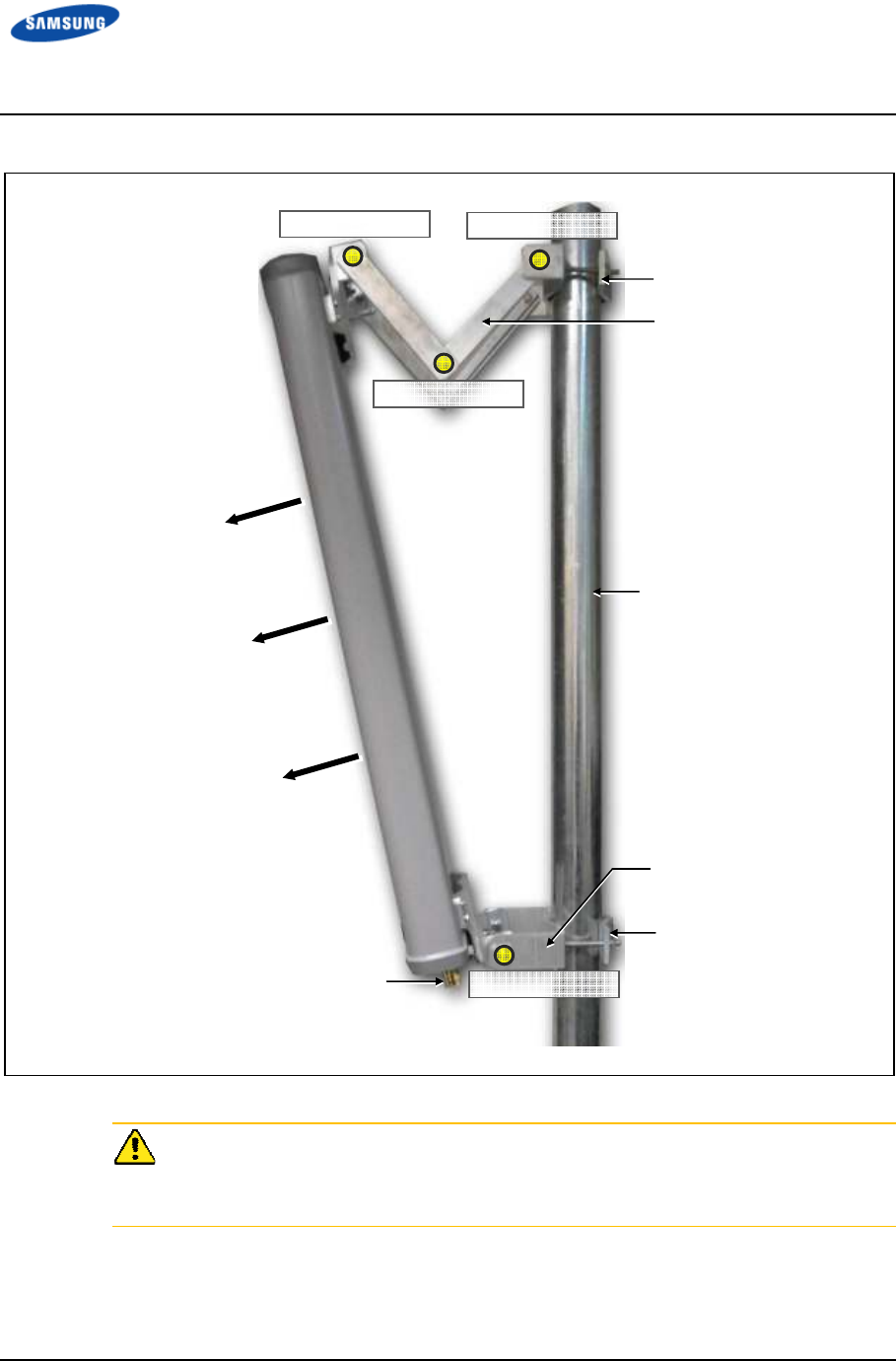
Error! Use the Home tab to apply 제목 8 to the text that
you want to appear here. Error! Use the Home tab to apply 제목 8 to the text that you want to
appear here.
LTE TDD Outdoor Pico eNB Installation Manual v1.0 94
©Samsung Proprietary and Confidential
Antenna Input Port
Pole
Main Radiation Direction
Upper Fixing Clamp
Lower Fixing Clamp
Upper Guide Clamp
Lower Guide Clamp
Guide Clamp Bolt_2
Guide Clamp Bolt_1
Guide Clamp Bolt_3
Guide Clamp Bolt_4
Figure 48. Sector Antenna
When you install the antenna, the antenna must be within the protective angle
(left/right side 45° each from the central axis) to prevent the antenna from
lightning damage.
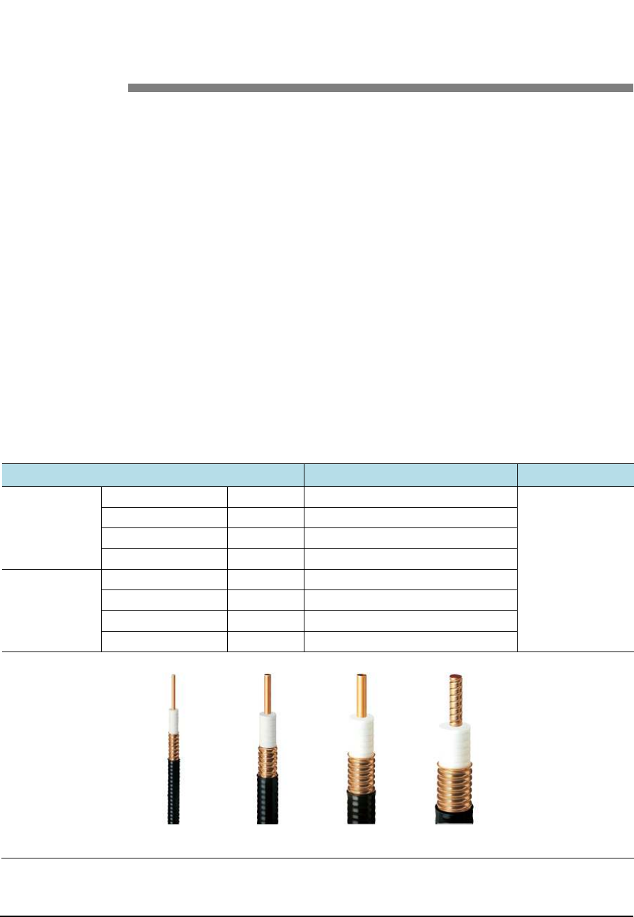
LTE TDD Outdoor Pico eNB Installation Manual v1.0 95
©Samsung Proprietary and Confidential
Appendix D
Appendix D Appendix D
Appendix D Installing Feeder
Installing Feeder Installing Feeder
Installing Feeder
Cable
CableCable
Cable
Cautions When Installing Feeder Cable
Follow these guidelines when installing the feeder cable (GPS/RF cable).
• Put a plate to work to minimize damage to the surface of the feeder cable.
If there is external damage of the feeder cable, cut the damaged part and
rework the wiring.
• After connecting the antenna to the feeder cable, finish the connection part of
the contracted pipe using the contracted tube.
• Attach labels to both ends of the feeder cable.
• Tightly connect the cabinet, antenna, and lightening arrestor to the feeder cable
to prevent generating a reflected wave.
• Maximize the curvature radius. Refer to Table 34. Curvature Radius of Feeder
Cable for Outdoor through Table 36. Curvature Radius of LDF4-50A.
Table 36. Curvature Radius of Feeder Cable for Outdoor
Specification
SpecificationSpecification
Specification
Allowed Radius of Curvature
Allowed Radius of CurvatureAllowed Radius of Curvature
Allowed Radius of Curvature
Remark
RemarkRemark
Remark
LS Feeder
Line
HFC-12D 1/2 in. 125 mm Outdoor
HFC-22D 7/8 in. 250 mm
HFC-33D 1-1/4 in. 380 mm
HFC-42D 1-5/8 in. 510 mm
RFS Feeder
Line
LCF12-50 1/2 in. 125 mm
LCF78-50 7/8 in. 250 mm
LCFS114-50 1-1/4 in. 380 mm
LCF158-50 1-5/8 in. 500 mm
1/2 in.
7/8 in.
1
-
1/4 in.
1
-
5/8 in.
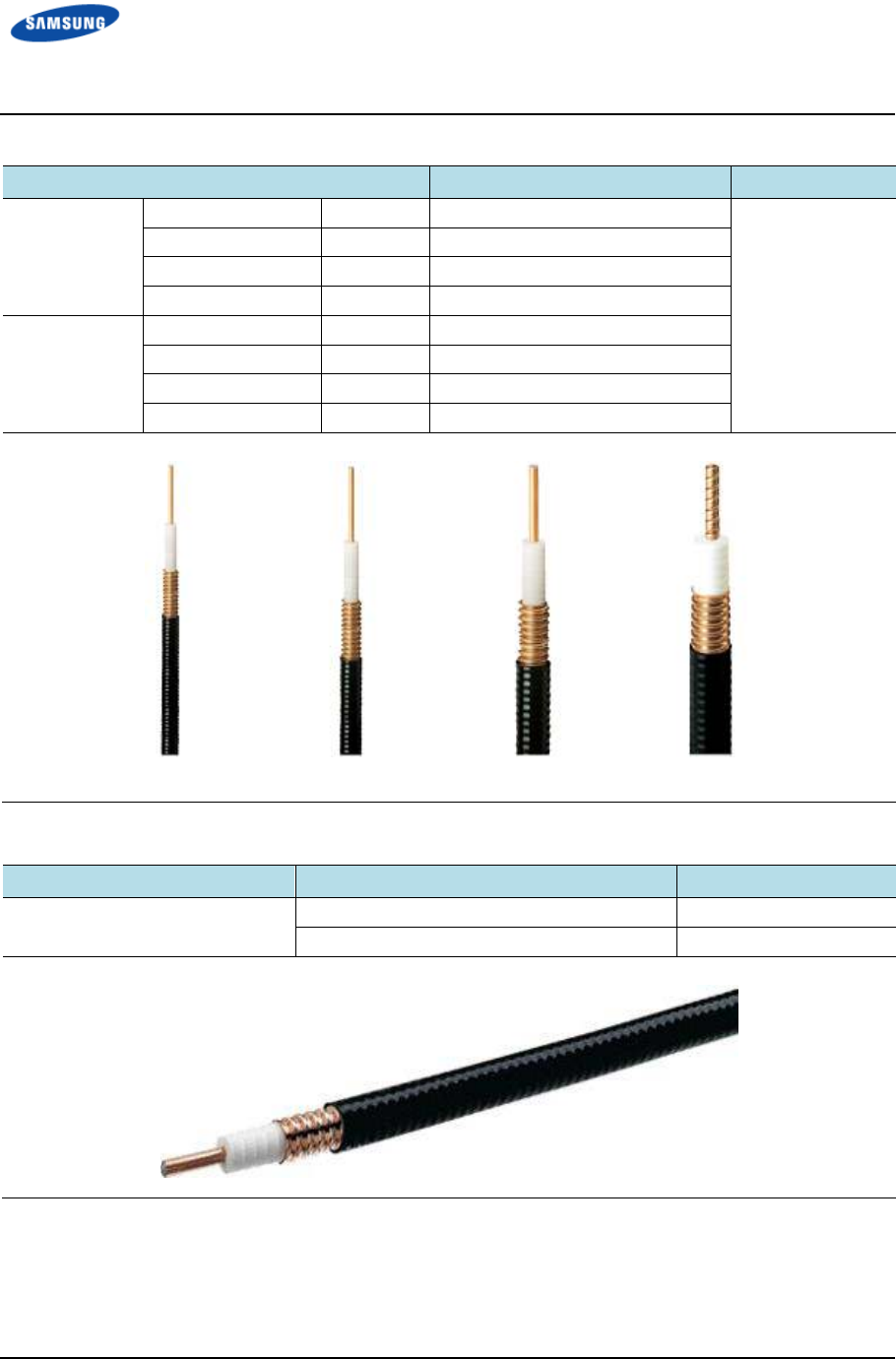
Error! Use the Home tab to apply 제목 8 to the text that
you want to appear here. Error! Use the Home tab to apply 제목 8 to the text that you want to
appear here.
LTE TDD Outdoor Pico eNB Installation Manual v1.0 96
©Samsung Proprietary and Confidential
Table 37. Curvature Radius of Feeder Cable for Indoor (Based on LS Feeder Line)
Specification
SpecificationSpecification
Specification
Allowed Radius of Curvature
Allowed Radius of CurvatureAllowed Radius of Curvature
Allowed Radius of Curvature
Remark
RemarkRemark
Remark
LS Feeder
Line
HFSC 6D 1/4 in. 25 mm Indoor
HFSC 10D 3/8 in. 0.98 in. (25 mm)
HFSC 12D 1/2 in. 1.26 in. (32 mm)
HFSC 22D 7/8 in. 4.92 in. (125 mm)
RFS Feeder
Line
SCF14-50 1/4 in. 0.98 in. (25 mm)
SCF38-50 3/8 in. 0.98 in. (25 mm)
SCF12-50 1/2 in. 1.26 in. (32 mm)
UCF78-50 7/8 in. 4.92 in. (125 mm)
Table 38. Curvature Radius of LDF4-50A
Specification
SpecificationSpecification
Specification
Allowed Radius of Curvature
Allowed Radius of CurvatureAllowed Radius of Curvature
Allowed Radius of Curvature
Remark
RemarkRemark
Remark
LDF4-50A 2 inch (50.8 mm) Installation
5 inch (127.0 mm) Repeated
1/4 in.
3/8 in.
1/2 in.
7/8 in.
Error! Use the Home tab to apply 제목 8 to the text that
you want to appear here. Error! Use the Home tab to apply 제목 8 to the text that you want to
appear here.
LTE TDD Outdoor Pico eNB Installation Manual v1.0 97
©Samsung Proprietary and Confidential
When installing a feeder line, the radius of curvature of the sections where cables
bend must be at least the minimum required radius of curvature. If the radius of
curvature for the feeder line installation is less than the allowed minimum, it may
affect the performance of the system.
• Ensure that the feeder cable does not interfere with steel towers, ladders, and
areas used by people.
• Connect the connector to the antenna in a straight line. After the connection,
do not apply excessive force.
• Use the vinyl tape for electricity and heat shrink tubing for the external
exposed part of the connector.
• Wrap the self-bonding rubber tape overlapping (keep a distance as the half size
of rubber tape) the connector connection part. Wrap the vinyl tape for
electricity twice or more and then cover with the jelly-type Heat Shrink tubing.
Connecting the feeder cable connector is a critical process. It must be performed
by qualified personnel.
Table 39. Connector Connection Torque Value
Connector
ConnectorConnector
Connector
Torque Value
Torque ValueTorque Value
Torque Value
SMA connector 0.18 lbfft (2.5 kgfcm)
TNC connector 0.65 lbfft (9 kgfcm)
N-type connector 1.45 lbfft (20 kgfcm)
Din-type connector 14.46 lbfft (200 kgfcm)
Mini DIN-type connector 8 lbfft (110.4 kgfcm)
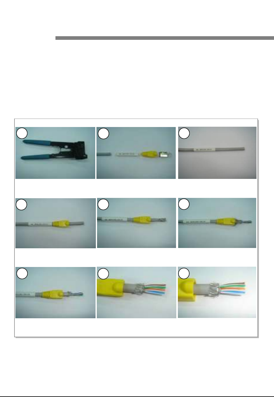
LTE TDD Outdoor Pico eNB Installation Manual v1.0 98
©Samsung Proprietary and Confidential
Appendix E
Appendix E Appendix E
Appendix E Connector
Connector Connector
Connector
Assembly
AssemblyAssembly
Assembly
RJ-45 (Shield Type)
The procedure to assemble the RJ-45 (shield type) connector is shown in Figure
49. Assembling the RJ-45 Connector (Shield Type) (1) and Figure 50. Assembling
the RJ-45 Connector (Shield Type) (2).
Figure 49. Assembling the RJ-45 Connector (Shield Type) (1)
1) and 2) Prepare work tools and materials.
4) Pass the cable through the RJ-45
cap.
5) Remove the coating 17 mm from
the end.
6) Push the shield backward and cut
the aluminum shield.
7) Cut the shield leaving 5 mm of it. 8) Arrange the cable in reference to
the pin map.
9) Cut the cable to make it 12 mm
long.
3) Pass the cable through the
marking tube.
1 2 3
4 5 6
7 8 9
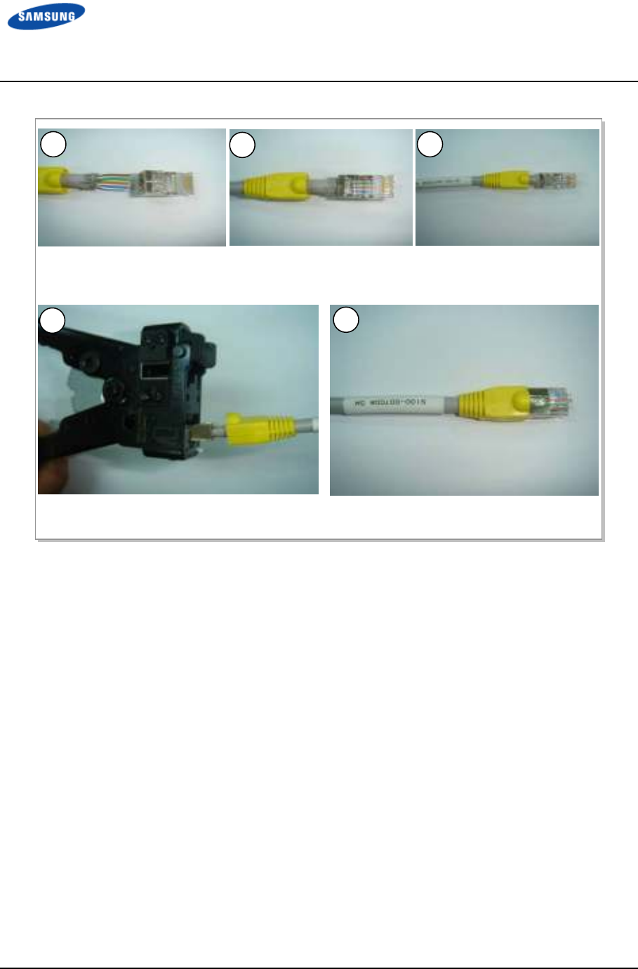
Error! Use the Home tab to apply 제목 8 to the text that
you want to appear here. Error! Use the Home tab to apply 제목 8 to the text that you want to
appear here.
LTE TDD Outdoor Pico eNB Installation Manual v1.0 99
©Samsung Proprietary and Confidential
Figure 50. Assembling the RJ-45 Connector (Shield Type) (2)
10) Insert the RJ-45 modular plug. 11) Ensure that the shield does not
get in the RJ-45 modular plug.
12) Insert the cable completely into
the RJ-45 modular plug.
13) Compress the plug using the tool. 14) Compress the marking tube to finish the
assembly.
10 11 12
13 14
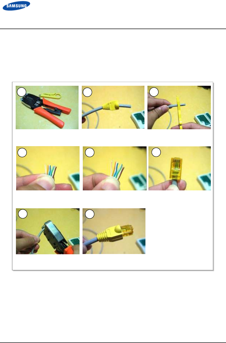
Error! Use the Home tab to apply 제목 8 to the text that
you want to appear here. Error! Use the Home tab to apply 제목 8 to the text that you want to
appear here.
LTE TDD Outdoor Pico eNB Installation Manual v1.0 100
©Samsung Proprietary and Confidential
RJ-45 (Normal Type)
The RJ-45 (normal type) connector assembly procedure is shown in Figure 51.
Assembling the RJ-45 Connector (Normal Type).
Figure 51. Assembling the RJ-45 Connector (Normal Type)
1) Prepare work tools and materials. 2) Insert the RJ-45 cap to the cable. 3) Remove the coating 17
mm from
the end.
4) Arrange the cable in reference to
the pin map.
5) Cut the cable to make it 12 mm
long.
1 2 3
4 5 6
7 8
7) Compress the plug using the
tool.
6) Insert the cable completely into
the RJ-45 modular plug.
8) Push the RJ-45 cap to the
connector.
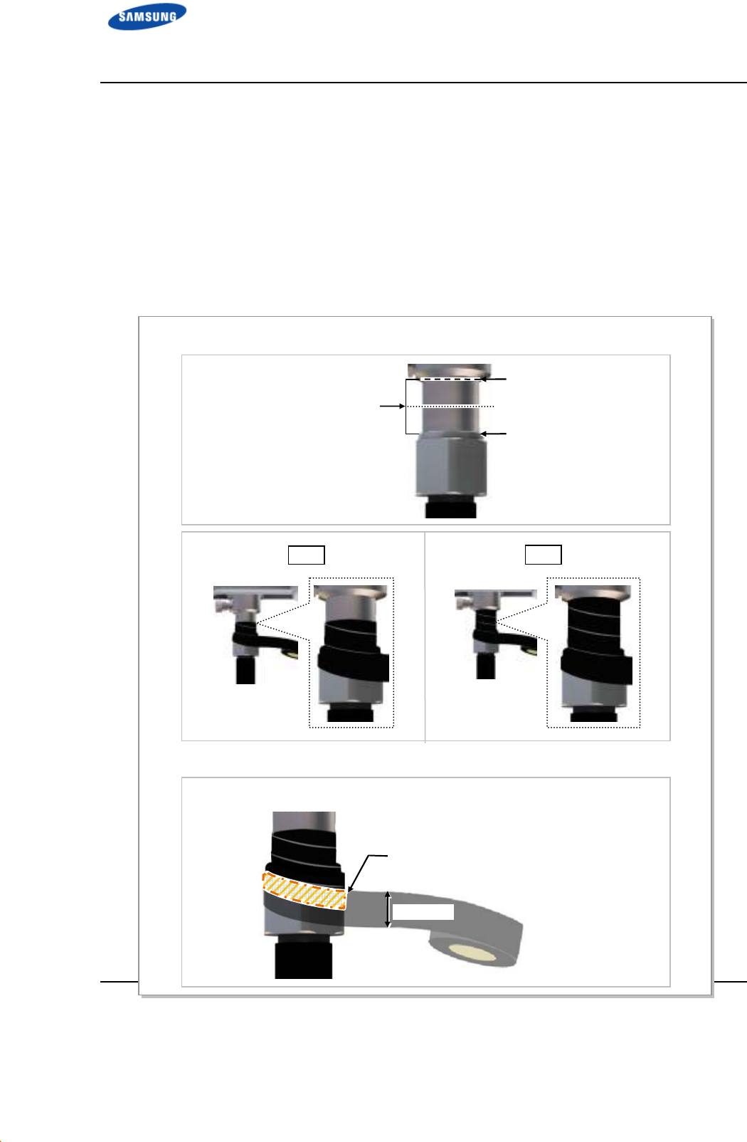
Error! Use the Home tab to apply 제목 8 to the text that
you want to appear here. Error! Use the Home tab to apply 제목 8 to the text that you want to
appear here.
LTE TDD Outdoor Pico eNB Installation Manual v1.0 101
©Samsung Proprietary and Confidential
Finishing the Connector Connection Part by
Tape
Check Items
Check the following items in Figure 52. Check Items for Finishing the Connector
Connection Part before finishing the connector connection part by tape.
Figure 52. Check Items for Finishing the Connector Connection Part
* Wrapping only the metal part of connector connection using insulation tape
* Wrapping the tape with overlapping
Starting and Ending points of
Insulation Tape
[Mid-point between (1) and (2)]
Wrap the tape using half of the tape width so it is overlapped.
(For both insulation tape and butyl tape)
Tape Width
Overlap area of tape
(1) Starting and Ending points
of Butyl tape
(2) Top side of Connector Nut
X
O
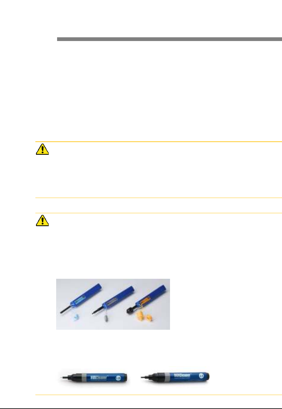
LTE TDD Outdoor Pico eNB Installation Manual v1.0 102
©Samsung Proprietary and Confidential
Appendix F
Appendix F Appendix F
Appendix F Cleaning Optic
Cleaning Optic Cleaning Optic
Cleaning Optic
Connector
ConnectorConnector
Connector
Cleaning Optic Connector
When connecting optical cable to the system, performance of system can be
decreased or fails can occur if ferrule section of optical connector is dirty due to
dust or foreign material. Therefore, worker should clean the optic connector before
connecting optic cable to the system to prevent this phenomenon. This manual
describes the method that cleans optic connector when using the IBCTM Brand
cleaner.
Caution When Connecting the Optical Cable
Check whether there is dust or foreign material on the cutting section of the
connector ferrule before connecting the optic cable, and keep this away from dust
or foreign material. If the cable is soiled with foreign material, do not blow to
remove them. Make sure to clean the connector in accordance with the cleaning
directions below.
When using Optic Connector Cleaner
When using optic connector cleaner, use the products shown in the example below
or their equivalents.
Ex) Manufacturer-USCONEC (http://www.usconec.com)
- IBCTM Brand Cleaner (P/N: 9393): For LC-LC and MU Connector Cleaning
- IBCTM Brand Cleaner (P/N: 9392): For SC Connector Cleaning
- IBCTM Brand Cleaner (P/N: 12910): For ODC Connector Cleaning
Manufacturer-TheFibers (www.thefibers.com)
- HuxCleaner 1.25 mm Type: For LC and MU Connector Cleaning
- HuxCleaner 2.5 mm Type: For SC, FC and ST Connector Cleaning
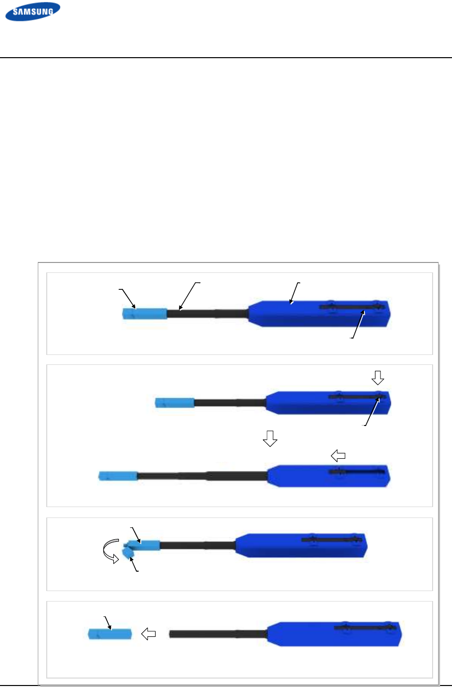
Error! Use the Home tab to apply 제목 8 to the text that
you want to appear here. Error! Use the Home tab to apply 제목 8 to the text that you want to
appear here.
LTE TDD Outdoor Pico eNB Installation Manual v1.0 103
©Samsung Proprietary and Confidential
IBCTM Brand Cleaner
Method that uses IBCTM Brand Cleaner is as follows:
IBCTM Brand type Cleaner (P/N 9393)
Method that uses IBCTM Brand Cleaner (P/N 9393) for LC-LC and MU
connector is as follows:
Figure 53. Optic Connector Cleaner (IBCTM Brand Type Cleaner: P/N 9393)
Guide Cap
Nozzle Outer Shell
Lock Button
Lock Button
(for Extend Nozzle)
Guide Cap Cover
Guide Cap
Guide Cap
[Optic Connector Cleaner Configuration]
[Nozzle Extension]
[In Case of LC type Connector (Plug)]
[In Case of LC type Connector (Jack)]
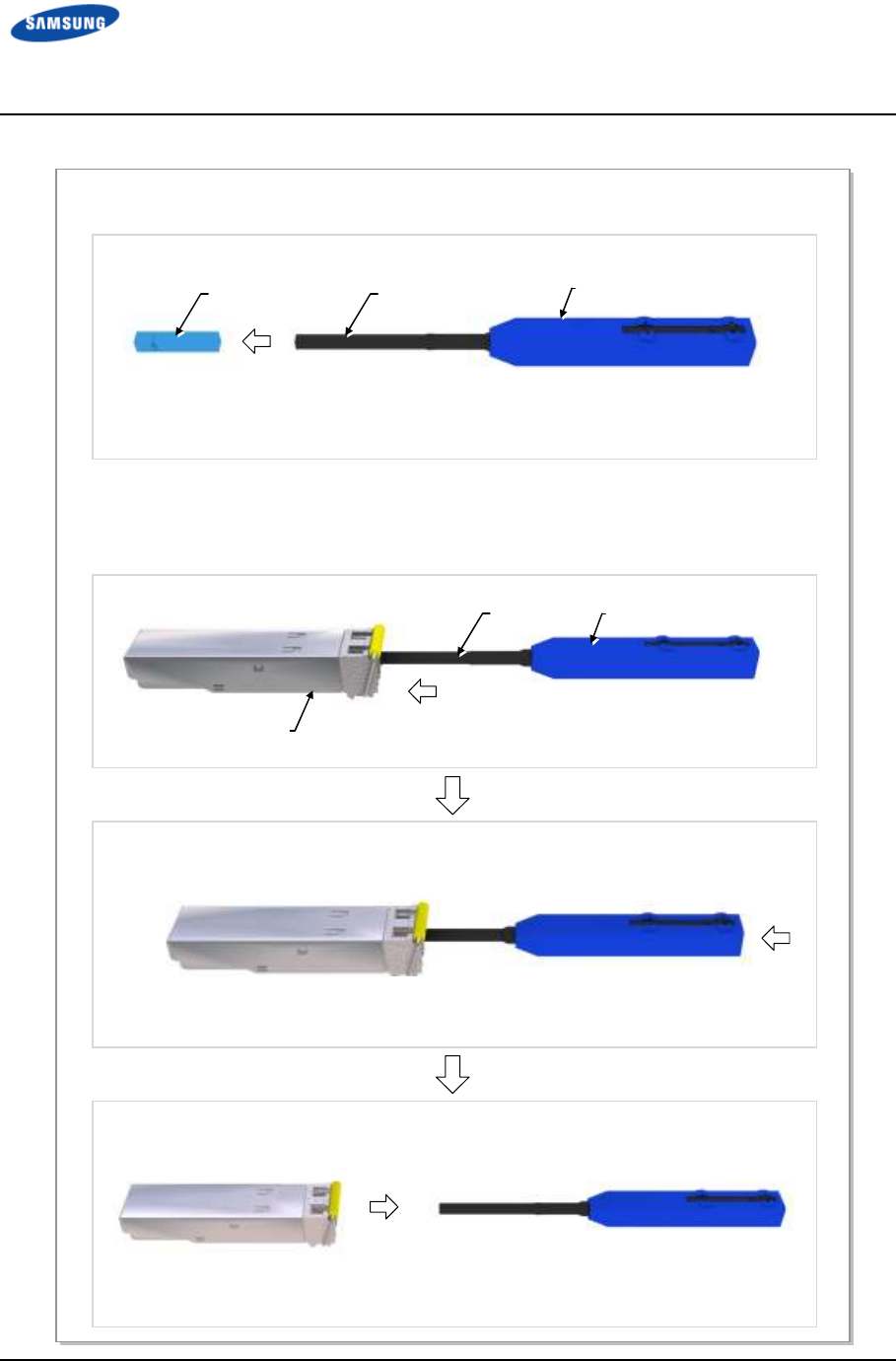
Error! Use the Home tab to apply 제목 8 to the text that
you want to appear here. Error! Use the Home tab to apply 제목 8 to the text that you want to
appear here.
LTE TDD Outdoor Pico eNB Installation Manual v1.0 104
©Samsung Proprietary and Confidential
Figure 54. Optic Module Cleaning (LC type Jack)
1) To clean the optic module, remove the guide cap from the cleaner (P/N: 9393).
Guide Cap
Nozzle Outer Shell
Optic Module
Nozzle Outer Shell
[IBC Brand Cleaner: P/N 9393]
2) Insert a cleaner guide cap to every ferrule of the optic module. Clean it by
pushing the outer shell toward the nozzle until you hear the sound of the
detergent being sprayed. (Repeat once or twice.)
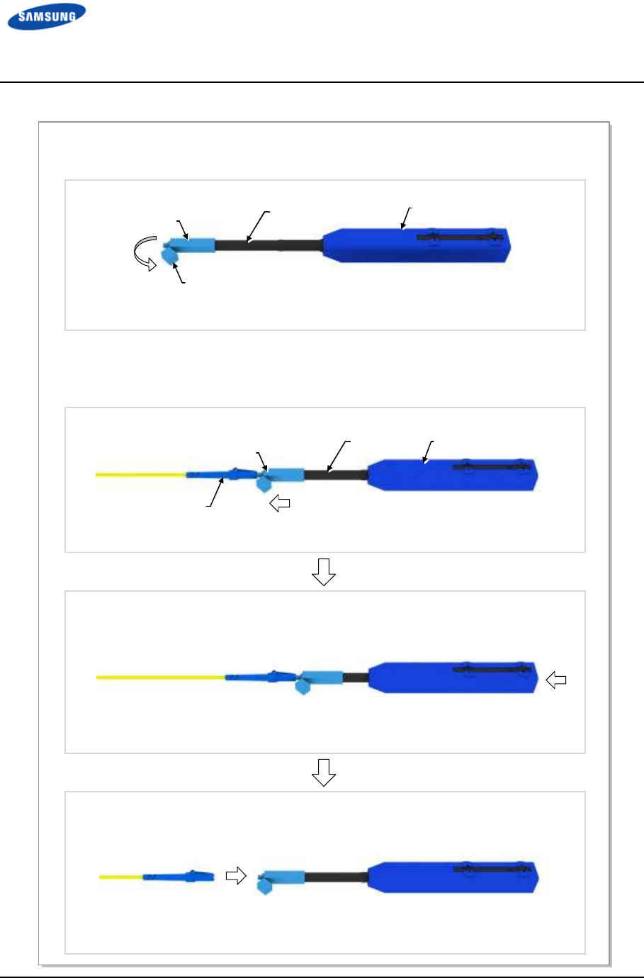
Error! Use the Home tab to apply 제목 8 to the text that
you want to appear here. Error! Use the Home tab to apply 제목 8 to the text that you want to
appear here.
LTE TDD Outdoor Pico eNB Installation Manual v1.0 105
©Samsung Proprietary and Confidential
Figure 55. Optic Cable Connector Cleaning (LC type plug)
1) To clean the optic cable connector, open the guide cap cover from the cleaner
(P/N: 9393)
2) Insert a cleaner guide cap to every ferrule of the optic cable connector. Clean it
by pushing the outer shell toward the nozzle until you hear the sound of the
detergent being sprayed. (Repeat once or twice.)
Guide Cap
Nozzle Outer Shell
Guide Cap Cover
Guide Cap
Nozzle Outer Shell
LC Type Connector
[IBC Brand Cleaner: P/N 9393]
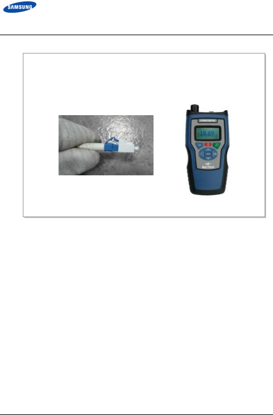
Error! Use the Home tab to apply 제목 8 to the text that
you want to appear here. Error! Use the Home tab to apply 제목 8 to the text that you want to
appear here.
LTE TDD Outdoor Pico eNB Installation Manual v1.0 106
©Samsung Proprietary and Confidential
Figure 56. Measuring the Optical Output and Connecting the Optic Connector
1) Check the optical output again using an optic power meter.
2) If the optical output measurement result meets the reference value, clean the
connector again and connect it. If the measurement result does not meet the
reference value, discard the cable, replace it with a new cable, and then clean
the new one and connect it to the system
[LC/PC Plug]
[Optic Power meter]
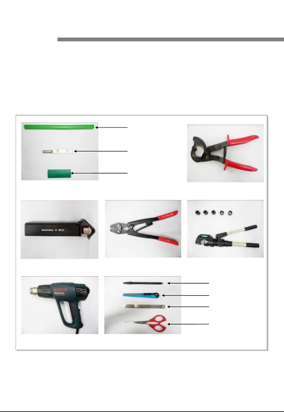
LTE TDD Outdoor Pico eNB Installation Manual v1.0 107
©Samsung Proprietary and Confidential
Appendix G
Appendix G Appendix G
Appendix G Pressure
Pressure Pressure
Pressure
Terminal Assembly
Terminal AssemblyTerminal Assembly
Terminal Assembly
Preparations
To connect a pressure terminal to a cable, prepare the items listed in Figure 57.
Preparations.
Figure 57. Preparations
[Cable Cutter]
[Wire Stripper] [Handheld Compressor] [Hydraulic Press]
[Heating Gun]
[Marking Pen]
[Cutter Blade]
[Steel Ruler]
[Scissors]
[Cable]
[Pressure Terminal]
[Heat Shrink Tube]
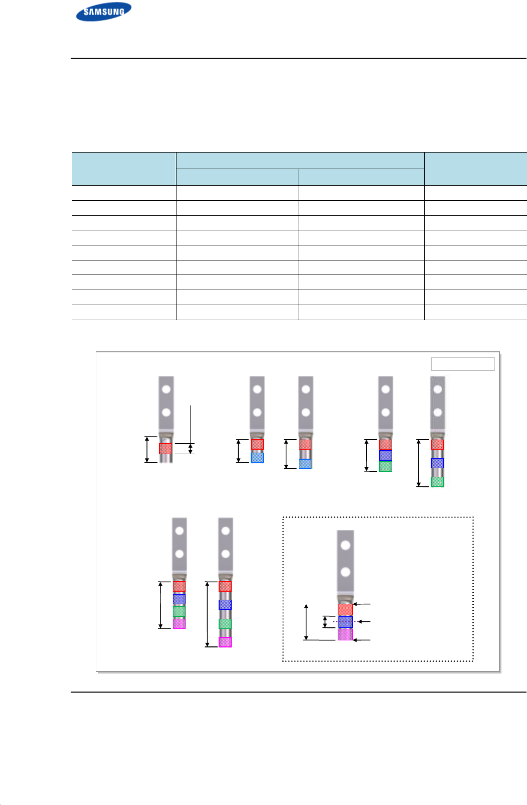
Error! Use the Home tab to apply 제목 8 to the text that
you want to appear here. Error! Use the Home tab to apply 제목 8 to the text that you want to
appear here.
LTE TDD Outdoor Pico eNB Installation Manual v1.0 108
©Samsung Proprietary and Confidential
Pressure Reference Table
Refer to the following tables and figures to assemble a pressure terminal to a cable.
Table 40. Pressure Reference Table for Pressure Terminal
Category
CategoryCategory
Category
Copper tube length of a pressure terminal
Copper tube length of a pressure terminalCopper tube length of a pressure terminal
Copper tube length of a pressure terminal
Number of
Number ofNumber of
Number of
pressure
pressure pressure
pressure
points
pointspoints
points
mm
mmmm
mm
In.
In.In.
In.
Hand 11 mm or less 0.43 in. 1
Hand 12~15 mm 0.47~0.59 in. 2
Hand 16~23 mm 0.63~0.91 in. 3
Hand 24~32 mm 0.94~1.26 in. 4
Hand 33 mm or more 1.3 in. or more 5
Hydraulic 30 mm or less 1.18 in. or less 2
Hydraulic 31~47 mm 1.22~1.85 in. 3
Hydraulic 48~63 mm 1.89~2.48 in. 4
Hydraulic 64 mm or more 2.52 in. or more 5
Figure 58. Pressure Reference Drawing (Handheld Compressor)
[1-spot] [2-spot] [3-spot]
[4-spot]
Unit: in. (mm)
0.43 (11)
0.18 (4.5)
0.47 (12)
0.59 (15)
0.63 (16)
0.91 (23)
0.94 in. (24)
1.26 (32)
0.63 (16)
0.18 (4.5)
Copper Tube Starting
Middle of Copper Tube
Arbitrary Fixing
Reference Points
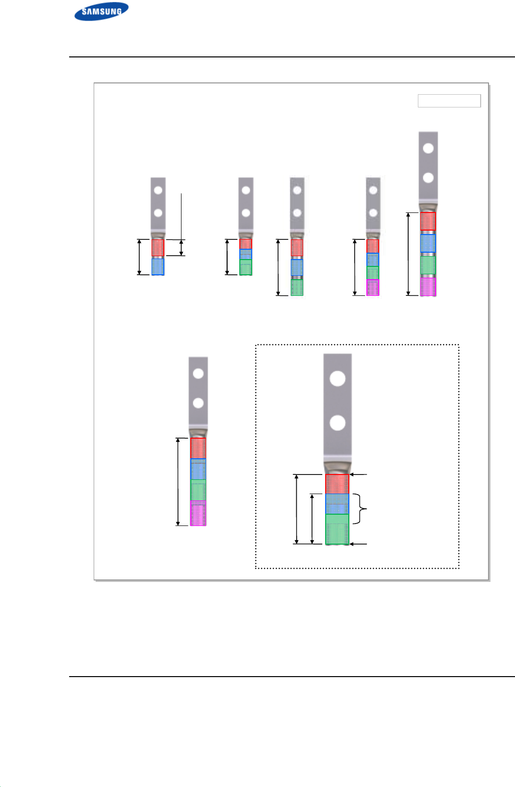
Error! Use the Home tab to apply 제목 8 to the text that
you want to appear here. Error! Use the Home tab to apply 제목 8 to the text that you want to
appear here.
LTE TDD Outdoor Pico eNB Installation Manual v1.0 109
©Samsung Proprietary and Confidential
Figure 59. Pressure Reference Drawing (Hydraulic Press)
Unit: in. (mm)
[2-spot] [3-spot] [4-spot]
1.18 (30)
[4-spot]
Copper Tube
Starting
Duplicate Pressure
Arbitrary Fixing
Reference Points
0.53 (13.5)
1.22 (31)
0.53 (13.5)
1.22 (31)
1.85 (47)
1.89 (48)
2.48 (63)
2.52 (64)

Error! Use the Home tab to apply 제목 8 to the text that
you want to appear here. Error! Use the Home tab to apply 제목 8 to the text that you want to
appear here.
LTE TDD Outdoor Pico eNB Installation Manual v1.0 110
©Samsung Proprietary and Confidential
Table 41. Compressor Specifications per Cable Thickness
Cable Size
Cable Size Cable Size
Cable Size
(mm
(mm(mm
(mm
2
22
2
)
))
)
Press Size
Press SizePress Size
Press Size
Small Handheld Press
Small Handheld PressSmall Handheld Press
Small Handheld Press
Large Handheld Press
Large Handheld PressLarge Handheld Press
Large Handheld Press
(AK
(AK(AK
(AK-
--
-38,
38, 38,
38, 100)
100)100)
100)
Hydraulic Press
Hydraulic PressHydraulic Press
Hydraulic Press
(IZUMI Hexagonal Dies)
(IZUMI Hexagonal Dies)(IZUMI Hexagonal Dies)
(IZUMI Hexagonal Dies)
2.5 2 X X
4 2 X X
6 5.5 X X
10 8 8 X
16 14 14 16
25 22 22 25
35 38 38 35
50 X 60 50
70 X 80 70
95 X 100 95~300
Error! Use the Home tab to apply 제목 8 to the text that
you want to appear here. Error! Use the Home tab to apply 제목 8 to the text that you want to
appear here.
LTE TDD Outdoor Pico eNB Installation Manual v1.0 111
©Samsung Proprietary and Confidential
Assembling Pressure Terminal
Use the following figures for assembling a pressure terminal to a cable.
Strip the Cable Sheath
Figure 60. Stripping Cable Sheath (1)
4) Put the cable into the clamp, locate the blade on the marking position, and push it into the sheath.
5) Align the stripper perpendicular to the cable and rotate it more than two laps.
1) Mark the cable, after checking the inside length of a pressure terminal.
2) Adjust the length of the cutter blade according to the sheath thickness of the cable.
3) Push the clamp with your thumb to secure a space for the cable.
Error! Use the Home tab to apply 제목 8 to the text that
you want to appear here. Error! Use the Home tab to apply 제목 8 to the text that you want to
appear here.
LTE TDD Outdoor Pico eNB Installation Manual v1.0 112
©Samsung Proprietary and Confidential
Figure 61. Stripping Cable Sheath (2)
6) Push the lever of the stripper to the right to turn its blade at 90°.
8) Remove the sheath.
7) Move the stripper to the end of cable while maintaining the stripper perpendicular to the cable.
you want to appear here.
Error! Use the Home tab to apply
appear here.
LTE TDD Outdoor Pico eNB
Installation Manual
©Samsung Proprietary and Confidential
A wire stripper is used differently depending on its manufacturer or type.
Therefore, refer to the user manual enclosed with the product.
The specifications and cautions
Vender: Weidmuller
Model: Weidmuller
Specifications: For outer diameter 6
-
To prevent the cutter blade of
conductor, adjust the length of
thickness.
-
Make sure that the cutter blade goes into the cable sheath completely.
-
Rotate the wire stripper perpendicularly to the cable.
Error! Use the Home tab to apply
제목
Error! Use the Home tab to apply
제목
8 to the text that you want to
Installation Manual
v1.0
©Samsung Proprietary and Confidential
A wire stripper is used differently depending on its manufacturer or type.
Therefore, refer to the user manual enclosed with the product.
The specifications and cautions
for the
wire stripper described in this manual are:
Vender: Weidmuller
Model: Weidmuller
-AM25 (Order No-9001080000)
Specifications: For outer diameter 6
-24 mm
PVC sheath up to 4.5 mm
sheath cutting depth
To prevent the cutter blade of
the
wire stripper from touching the cable
conductor, adjust the length of
the
cutter blade by checking the cable sheath
Make sure that the cutter blade goes into the cable sheath completely.
Rotate the wire stripper perpendicularly to the cable.
[X]
[O]
제목
8 to the text that
8 to the text that you want to
113
A wire stripper is used differently depending on its manufacturer or type.
wire stripper described in this manual are:
wire stripper from touching the cable
cutter blade by checking the cable sheath
Make sure that the cutter blade goes into the cable sheath completely.
Error! Use the Home tab to apply 제목 8 to the text that
you want to appear here. Error! Use the Home tab to apply 제목 8 to the text that you want to
appear here.
LTE TDD Outdoor Pico eNB Installation Manual v1.0 114
©Samsung Proprietary and Confidential
Fixing Pressure Terminal (Handheld Compressor)
Figure 62. Fixing Pressure Terminal–Handheld Compressor (1)
1) Insert the conductor of the cable with the sheath stripped to the internal end of pressure terminal.
For a ring type pressure terminal, push it in until the conduct comes out 1 mm from the end of the terminal.
2) From the holes of the handheld compressor, select one that fits the pressure terminal.
3) Insert the pressure terminal in the selected hole.
4) Press the compressor to fix the pressure terminal and cable temporarily so the position can be changed
later.
Error! Use the Home tab to apply 제목 8 to the text that
you want to appear here. Error! Use the Home tab to apply 제목 8 to the text that you want to
appear here.
LTE TDD Outdoor Pico eNB Installation Manual v1.0 115
©Samsung Proprietary and Confidential
Figure 63. Fixing Pressure Terminal–Handheld Compressor (2)
5) Align the cable to the hole and firmly compress the pressure terminal to fix it securely.
6) Separate the pressure terminal from the handheld compressor. To unlock the compressor, press the
handle down until hearing a clicking sound.
you want to appear here.
Error! Use the Home tab to apply
appear here.
LTE TDD Outdoor Pico eNB
Installation Manual
©Samsung Proprietary and Confidential
A handheld compressor is used differently depending on its manufacturer or type.
Therefore, refer to the user manual enclosed with the product.
The specifications and cautions of
manual are:
Vender: GALLEX
Model: GL
-
Specification: 5.5 mm
Error! Use the Home tab to apply
제목
Error! Use the Home tab to apply
제목
8 to the text that you want to
Installation Manual
v1.0
©Samsung Proprietary and Confidential
A handheld compressor is used differently depending on its manufacturer or type.
Therefore, refer to the user manual enclosed with the product.
The specifications and cautions of
the
handheld compressor described in this
Vender: GALLEX
-
2045A-22
Specification: 5.5 mm
2
, 8 mm
2
, 14 mm
2
, 22 mm
2
(JIS)
6 mm
2
, 10 mm
2
, 16 mm
2
, 25 mm
2
(DIN)
제목
8 to the text that
8 to the text that you want to
116
A handheld compressor is used differently depending on its manufacturer or type.
handheld compressor described in this
Error! Use the Home tab to apply 제목 8 to the text that
you want to appear here. Error! Use the Home tab to apply 제목 8 to the text that you want to
appear here.
LTE TDD Outdoor Pico eNB Installation Manual v1.0 117
©Samsung Proprietary and Confidential
Fixing Pressure Terminal (Hydraulic Press)
Figure 64. Fixing Pressure Terminal–Hydraulic Press (1)
1) Among the dies of the hydraulic press, select one that fits to the pressure terminal.
Dies
Hydraulic Press
2) Assemble the dies to the pressing area of the compressor.
3) Insert the pressure terminal into the pressing area and fix it slightly by aligning it to the end of cable
sheath.
Error! Use the Home tab to apply 제목 8 to the text that
you want to appear here. Error! Use the Home tab to apply 제목 8 to the text that you want to
appear here.
LTE TDD Outdoor Pico eNB Installation Manual v1.0 118
©Samsung Proprietary and Confidential
Figure 65. Fixing Pressure Terminal–Hydraulic Press (2)
4) Move the compressor lever up and down to press the pressure terminal firmly.
5) Turn the top compressing lever clockwise and then push it down. When the pressing area of compressor
is loosened, remove the pressure terminal.
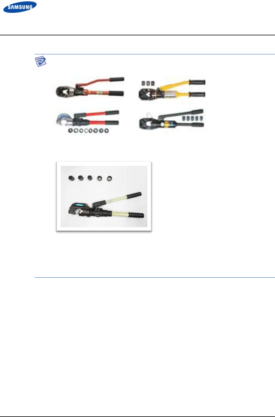
you want to appear here.
Error! Use the Home tab to apply
appear here.
LTE TDD Outdoor Pico eNB
Installation Manual
©Samsung Proprietary and Confidential
A hydraulic press is used differently depending on its manufacturer or type.
Therefore, refer t
The specifications and cautions of
Vender: IZUMI
Model: IZUMI
Specification: Circular 32~160 (SQ)
Error! Use the Home tab to apply
제목
Error! Use the Home tab to apply
제목
8 to the text that you want to
Installation Manual
v1.0
©Samsung Proprietary and Confidential
A hydraulic press is used differently depending on its manufacturer or type.
Therefore, refer t
o the user manual enclosed with the product.
The specifications and cautions of
the
hydraulic press described in this manual are:
Vender: IZUMI
Model: IZUMI
-EP-510B
Specification: Circular 32~160 (SQ)
Hex 14~325 (SQ)
제목
8 to the text that
8 to the text that you want to
119
A hydraulic press is used differently depending on its manufacturer or type.
hydraulic press described in this manual are:
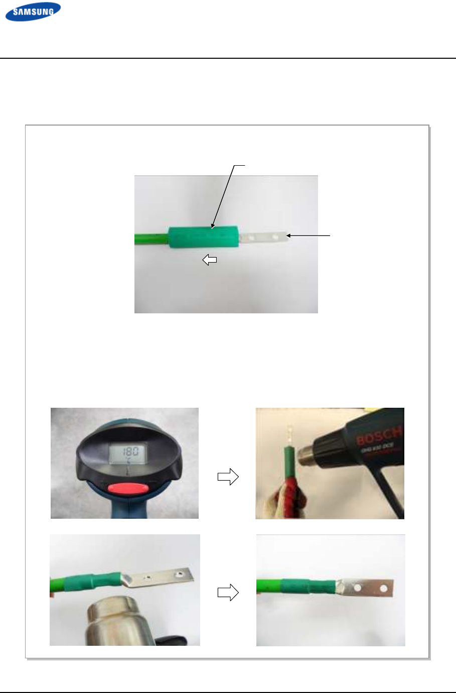
Error! Use the Home tab to apply 제목 8 to the text that
you want to appear here. Error! Use the Home tab to apply 제목 8 to the text that you want to
appear here.
LTE TDD Outdoor Pico eNB Installation Manual v1.0 120
©Samsung Proprietary and Confidential
Assembling Heat Shrink Tube
Figure 66. Assembling Heat Shrink Tube
2) Set the temperature of the heat gun to 180-200°C.
3) Cover the entire copper tube of the pressure terminal with a heat shrink tube.
4) Rotate the heat gun 360° to apply heat evenly to shrink the tube.
(Because the pressure terminal and the cable are hot due to the heat of the heating gun, be careful not to
burn yourself.)
1) After assembling the pressure terminal, move the heat shrink tube insert the cable to the end of pressure
terminal copper tube.
Heat Shrink Tube
Pressure Terminal
LTE TDD Outdoor Pico eNB Installation Manual v1.0 121
©Samsung Proprietary and Confidential
Appendix H
Appendix H Appendix H
Appendix H Standard Torque
Standard TorqueStandard Torque
Standard Torque
When you tighten the bolt to prevent the equipment and bolt from damage, refer to
the standard torque values in Table 42. Standard Torque Value for Tightening
Bolts and Table 43. Brass Bolts Torque Value. When the torque value for each
connection part is defined already, refer to the defined value.
Table 42. Standard Torque Value for Tightening Bolts
Bolt Spec.
Bolt Spec.Bolt Spec.
Bolt Spec.
Torque Value (kgf·cm)
Torque Value (kgf·cm)Torque Value (kgf·cm)
Torque Value (kgf·cm)
T
TT
Torque Value (N
orque Value (Norque Value (N
orque Value (N·
··
·m)
m)m)
m)
Torque Value (lbf·ft)
Torque Value (lbf·ft)Torque Value (lbf·ft)
Torque Value (lbf·ft)
M3 4.08~6.12 0.40~0.60 0.29~0.44
M4 9.52~14.28 0.93~1.40 0.69~1.03
M5 20.0~30.0 1.96~2.94 1.45~2.17
M6 33.28~49.92 3.26~4.90 2.41~3.61
M8 82.4~123.6 8.08~12.12 5.96~8.94
M10 166.4~249.6 16.32~24.48 12.03~18.05
M12 292.0~438.0 28.64~42.65 21.11~31.67
Table 43. Brass Bolts Torque Value
Bolt Spec.
Bolt Spec.Bolt Spec.
Bolt Spec.
Torque Value (kgf·cm)
Torque Value (kgf·cm)Torque Value (kgf·cm)
Torque Value (kgf·cm)
Torque Value (N.m)
Torque Value (N.m)Torque Value (N.m)
Torque Value (N.m)
Torque Value (lbf·ft)
Torque Value (lbf·ft)Torque Value (lbf·ft)
Torque Value (lbf·ft)
M6 29.98 ± 10% 2.94 ± 10% 2.17 ± 10%
M8 64.26 ± 10% 6.3 ± 10% 4.16 ± 10%
Torque value can be different depending on the material, characteristic, and
specification of the equipment and fastener. Make sure to check the proper torque
value for each specification of the equipment and fastener.

LTE
TDD Outdoor
Pico
eNB
Installation Manual
Document Version 1.0
©
2014
Samsung Electronics Co., Ltd.
All
rights reserved.