Samsung Electronics Co SLS-BP00AK Outdoor Pico eNB User Manual
Samsung Electronics Co Ltd Outdoor Pico eNB
UserManual.wiki
>
Samsung Electronics Co
>
SLS BP00AK User Manual
User Manual
Navigation menu
Upload a User Manual
Namespaces
Wiki Guide
HTML
PDF
Info
Views
User Manual
Discussion / Help
Navigation
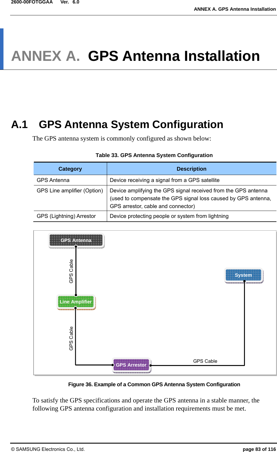
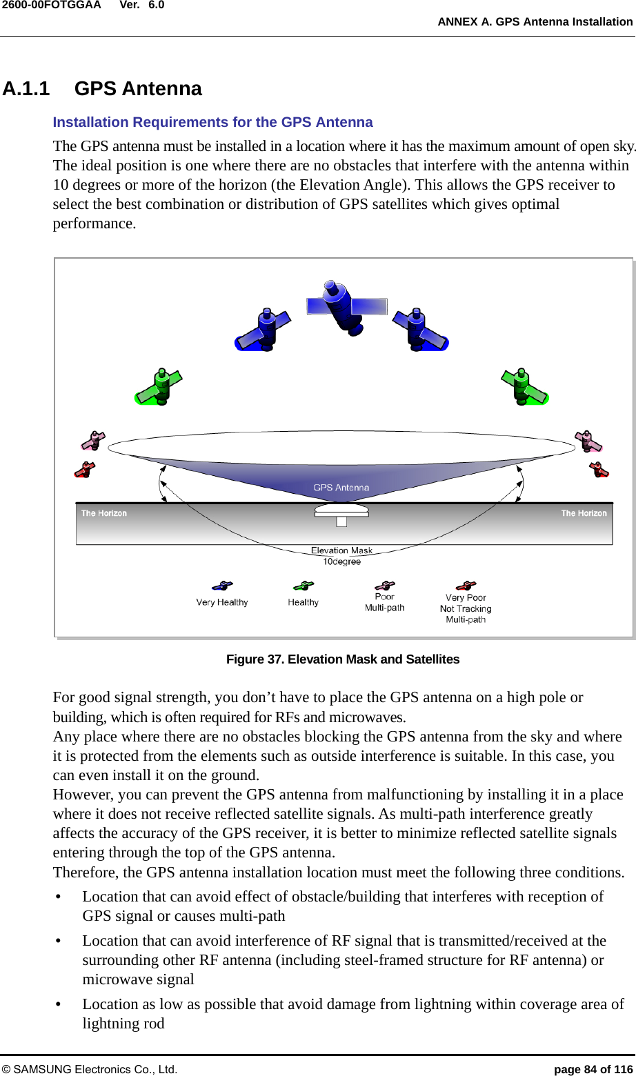
![Ver. CHAPTER 1. Before Installation © SAMSUNG Electronics Co., Ltd. page 18 of 116 1.0CHAPTER 1. Before Installation 1.1 System Configuration Outdoor Pico Configuration The configuration of Outdoor Pico is as follows: Figure 1. Outdoor Pico Configuration UnitT10.1PPS60) [Bottom View]18.90 (480) [Front View] [Top View] [Left View] [RiLMT View] [RDEBUG ew] 4.94 (125.5)](https://usermanual.wiki/Samsung-Electronics-Co/SLS-BP00AK/User-Guide-2282928-Page-18.png)
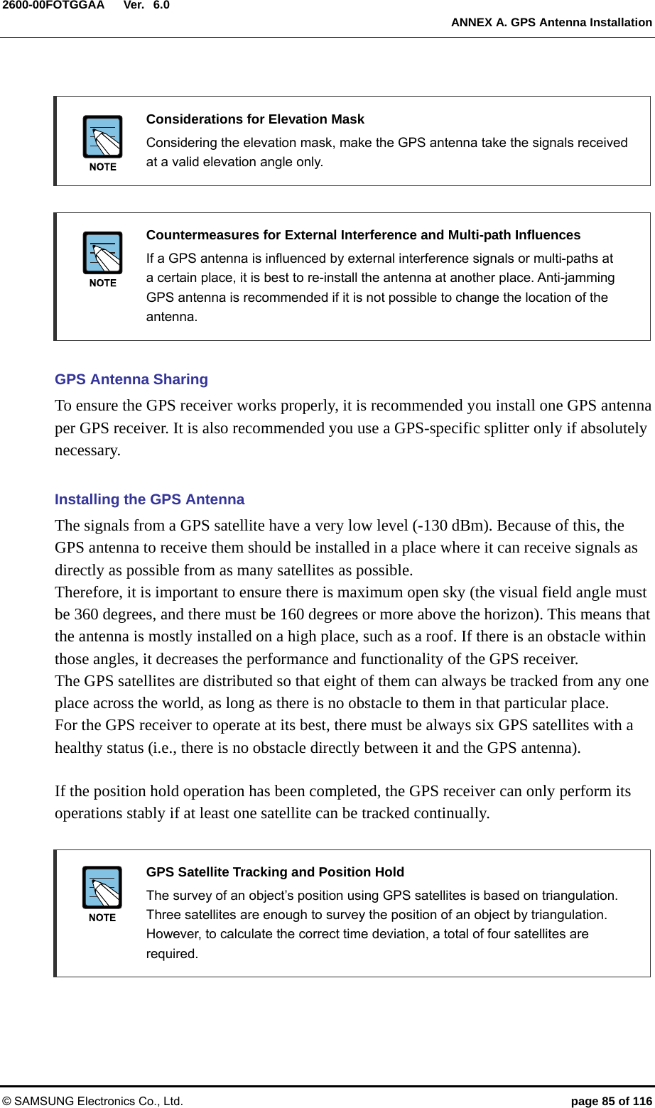
![Ver. CHAPTER 1. Before Installation © SAMSUNG Electronics Co., Ltd. page 19 of 116 1.0 External Interface of Outdoor Pico The external interface structure of Outdoor Pico is as follows: Figure 2. External Interface of Outdoor Pico GPSBH_OPT BH_ETH 110~220 VACTX_MON 0ANT_0ANT_1 TX_MON 1 FG 1PPS LMT DEBUG 10M [Bottom Window]](https://usermanual.wiki/Samsung-Electronics-Co/SLS-BP00AK/User-Guide-2282928-Page-19.png)
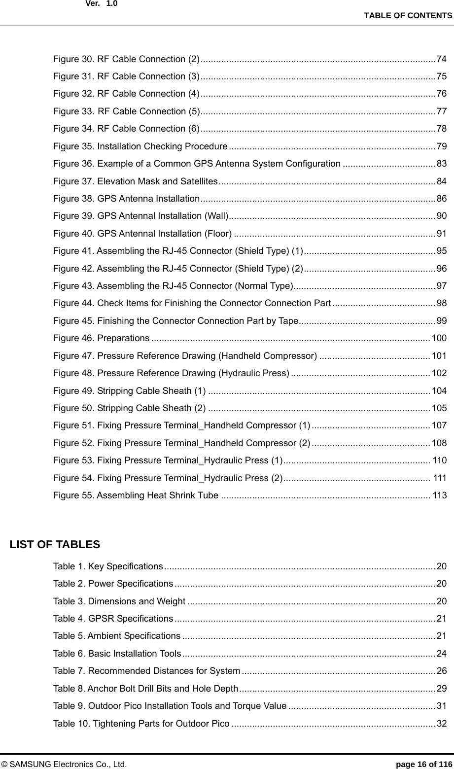
![Ver. CHAPTER 1. Before Installation © SAMSUNG Electronics Co., Ltd. page 20 of 116 1.01.2 Specifications Key Specifications The key specifications of the Outdoor Pico are as follows: Table 1. Key Specifications Category Specification Air specification FDD LTE Operating Frequency 1.9 GHz (Band 25) Channel Bandwidth 5/10 MHz Peak Throughput (with Category 3 UE) - 5 MHz BW: DL 32.1 Mbps (2x2 MIMO), UL 8.0 Mbps (1x2 SIMO)- 10 MHz BW: DL 65.2 Mbps (2x2 MIMO), UL 18.3 Mbps (1x2 SIMO)- Calculation condition: DL 0 % PHY error, UL 1 % PHY error Tx Power 4 W/Path (Total 8 W) Antenna Configuration 2Tx/2Rx Backhaul Gigabit Ethernet 1 port (Copper) Holdover 8 h Power Specifications The power specifications of the Outdoor Pico are as follows: Table 2. Power Specifications Category Standard Rated voltage 120-240 V With tolerance +/- 10% Rated current 2A Dimensions and Weight The dimensions and weight of the Outdoor Pico are as follows: Table 3. Dimensions and Weight Item Specification Size [in.(mm)], W × D × H 10.24 × 4.96 × 18.90 (260 × 126 × 480) or less Weight 22 lb (10 kg) @ 1.9 GHz](https://usermanual.wiki/Samsung-Electronics-Co/SLS-BP00AK/User-Guide-2282928-Page-20.png)
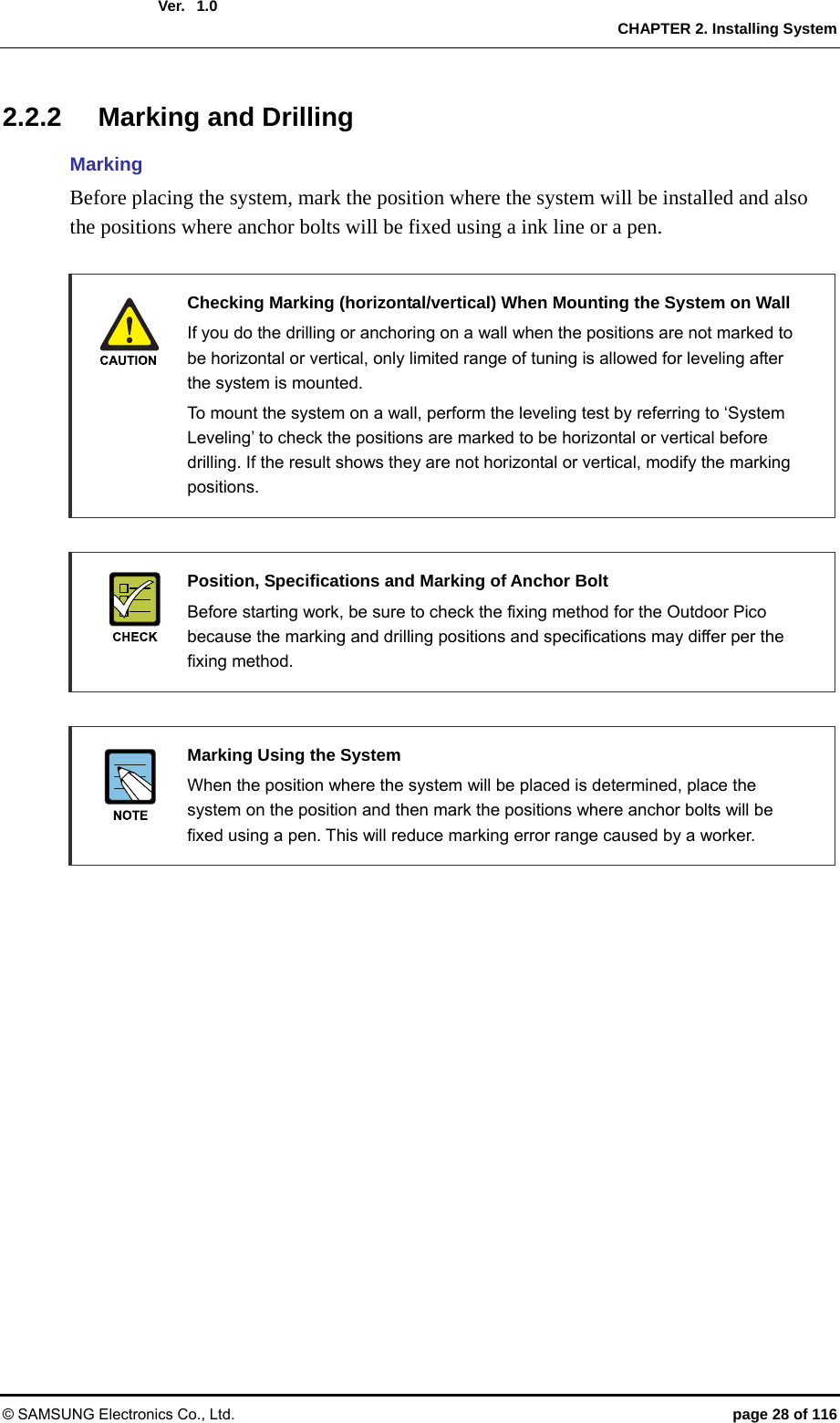
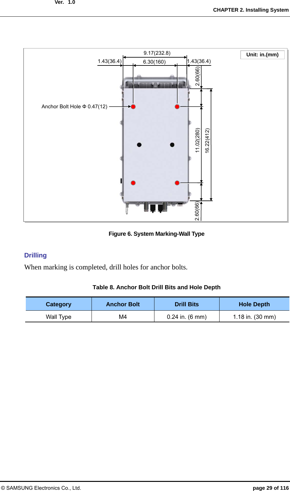
![Ver. CHAPTER 2. Installing System © SAMSUNG Electronics Co., Ltd. page 26 of 116 1.02.2 Foundation Work 2.2.1 System Arrangement A minimum distance must be secured around the Outdoor Pico, in each direction for installation and maintenance. Table 7. Recommended Distances for System Category Recommended Distances Front/Rear 31.5 in. (800 mm) or more Side 7.87 in. (200 mm) or more Top/Bottom 39.37 in. (1,000 mm) or more Figure 4. Outdoor Pico Arrangement(Wall Type) Unit: in. (mm)18.90 (480) [Front View][Top View]10.23 (260) ≒ 7.22 (183.5) 10.24 (260)](https://usermanual.wiki/Samsung-Electronics-Co/SLS-BP00AK/User-Guide-2282928-Page-26.png)
![Ver. CHAPTER 2. Installing System © SAMSUNG Electronics Co., Ltd. page 27 of 116 1.0 Figure 5. Outdoor Pico Arrangement(Pole Type) [Top View]Pole: (Ф 3~4.5 in. / Ф 76.3~114.3 mm) [Side View]Unit: in. ( mm)18.90 (480) 10.23 (260) ≒ 7.22 (183.5) ≒ 5.57 (141.6) Pole: (Ф 3~4.5 in. / Ф 76.3~114.3](https://usermanual.wiki/Samsung-Electronics-Co/SLS-BP00AK/User-Guide-2282928-Page-27.png)
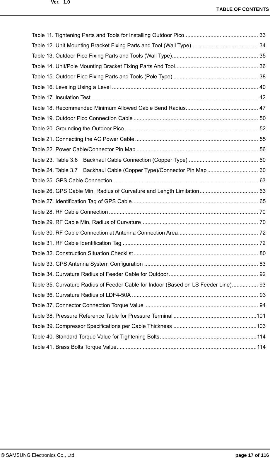
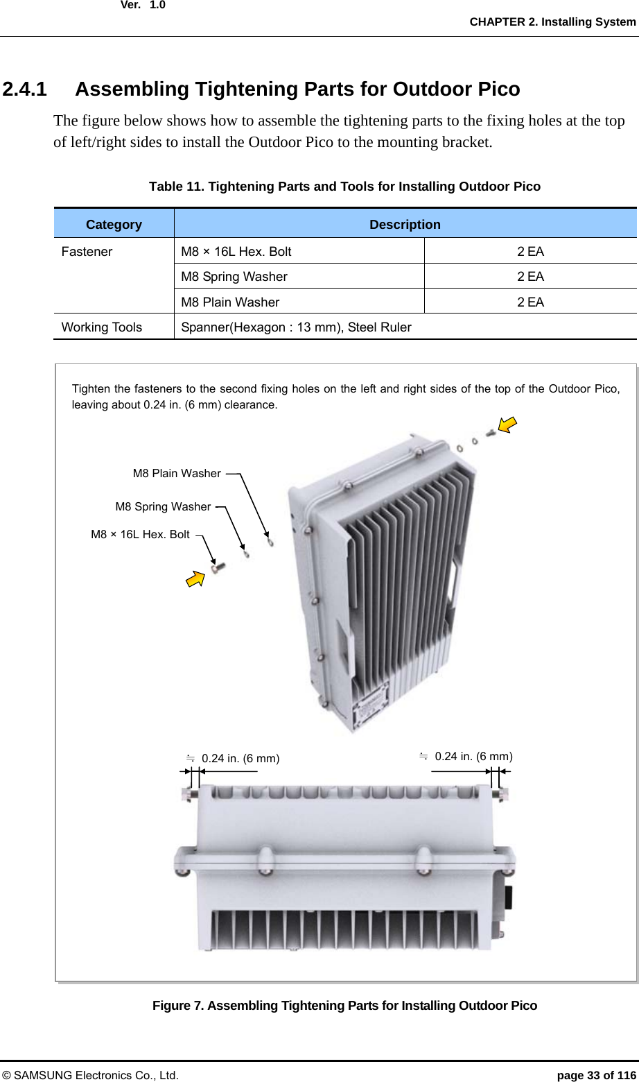
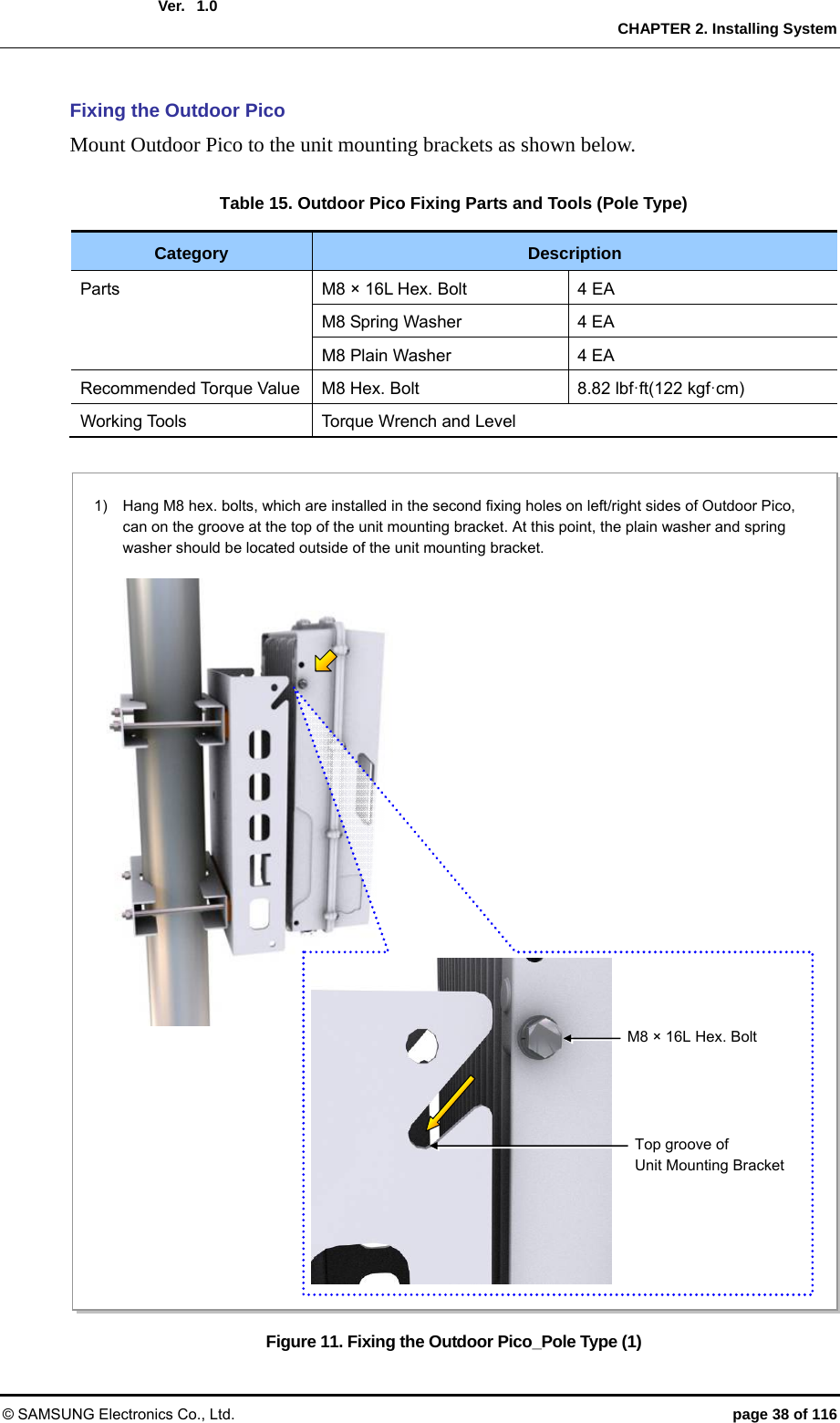
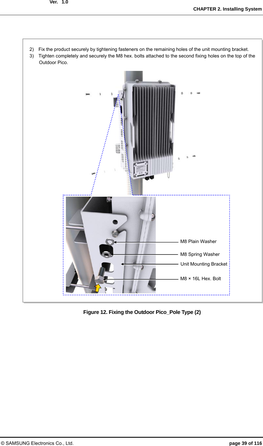
![Ver. CHAPTER 2. Installing System © SAMSUNG Electronics Co., Ltd. page 31 of 116 1.0 2.4 Fixing System The installation tools and assembly torque required to install and maintain the Outdoor Pico are as follows: Table 9. Outdoor Pico Installation Tools and Torque Value Category Installation Tools Torque Value A Maintenance Window Screw Star Pole Type Screw Driver : M4 0.87 lbf·ft(12 kgf·cm) B M6 SEMS Driver(+) : M6 1.45~2.17 lbf·ft (20~30 kgf·cm) C SMA Hexagon: 0.39 in.(10 mm) 0.36 lbf·ft(5.0 kgf·cm) D N-Type Hexagon: 0.75 in.(19 mm) 0.87 lbf·ft(12.0 kgf·cm) [Front View]‘D’‘B’ ‘D’ ‘D’ ‘C’‘C’‘A’ [Bottom View]‘A’](https://usermanual.wiki/Samsung-Electronics-Co/SLS-BP00AK/User-Guide-2282928-Page-31.png)
![Ver. CHAPTER 2. Installing System © SAMSUNG Electronics Co., Ltd. page 41 of 116 1.0 Figure 13. Leveling Using a Level (Wall Type) Figure 14. Leveling Using a Level (Pole Type) [Measuring Vertical Position] [Measuring Horizontal Position] [Pole Type] [Wall Type] [Measuring Vertical Position] [Measuring Horizontal Position]](https://usermanual.wiki/Samsung-Electronics-Co/SLS-BP00AK/User-Guide-2282928-Page-41.png)
![Ver. CHAPTER 2. Installing System © SAMSUNG Electronics Co., Ltd. page 43 of 116 1.0 Figure 15. Schematic Diagram for Insulation Test (Wall Type) Figure 16. Schematic Diagram for Insulation Test (Pole Type) Anchor Bolt[Megger] [Wall Type] Outdoor Pico Fixing Hex. Bolt M8 × 180LStud Bolt [Megger] [Pole Type] Outdoor Pico Fixing Hex. Bolt](https://usermanual.wiki/Samsung-Electronics-Co/SLS-BP00AK/User-Guide-2282928-Page-43.png)
![Ver. CHAPTER 3. Connecting Cables © SAMSUNG Electronics Co., Ltd. page 49 of 116 1.0 3.2 Cabling The cabling diagram of the Outdoor Pico is as follows: Figure 19. Cabling Diagram 5) RF Cable [AC Distributor] [MGB] [RF Antenna] 1) Frame Ground Cable[GPS Antenna] [Switch or Router] 2) Power Cable 3) Backhaul Cable(Copper) 4) GPS Cable 5) RF Cable](https://usermanual.wiki/Samsung-Electronics-Co/SLS-BP00AK/User-Guide-2282928-Page-49.png)
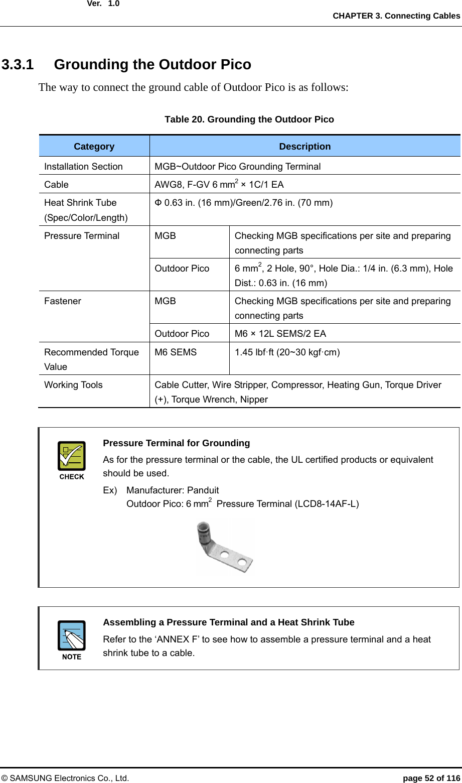
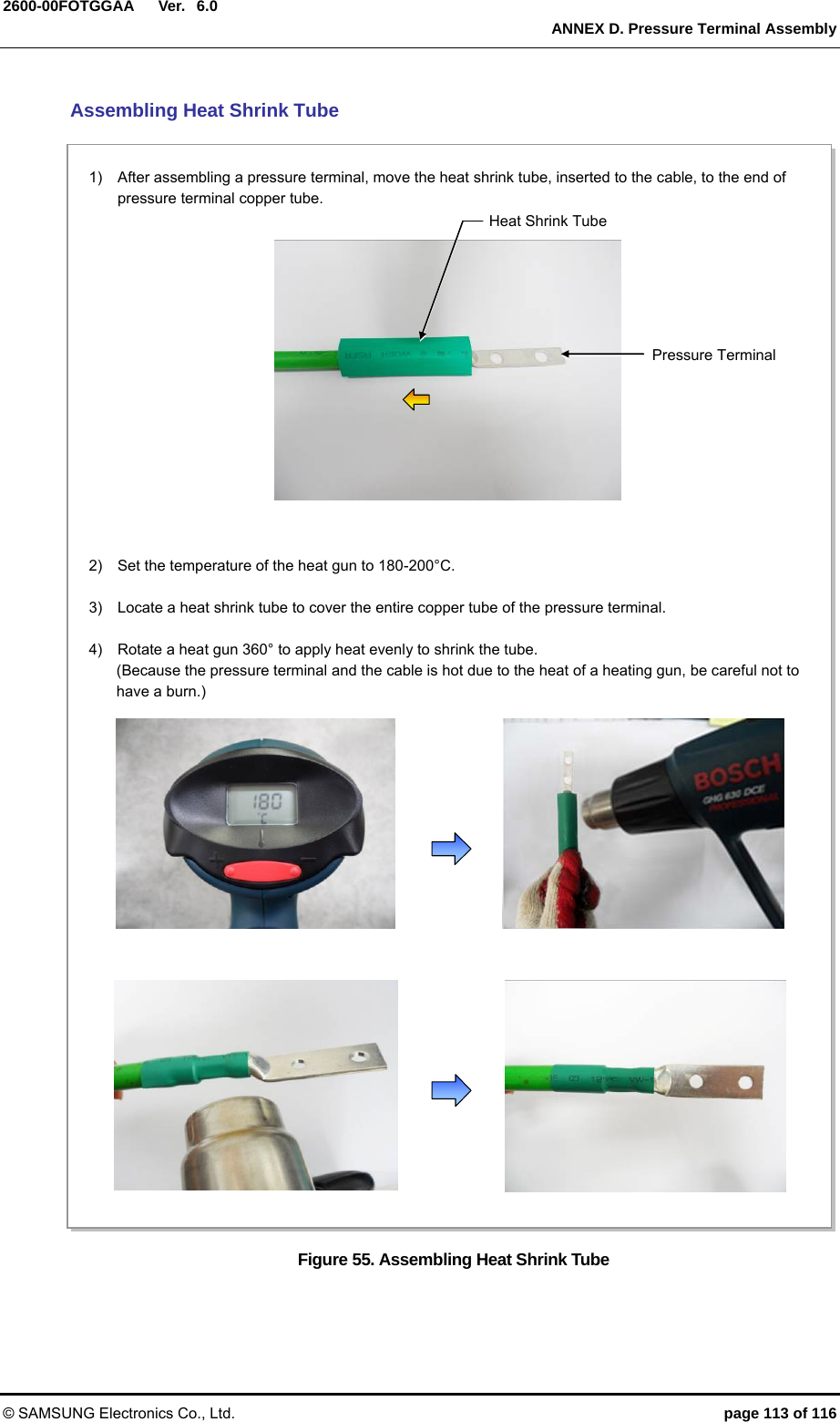
![Ver. CHAPTER 3. Connecting Cables © SAMSUNG Electronics Co., Ltd. page 53 of 116 1.0 Figure 20. Connection of the Outdoor Pico Ground Cable MGB1) Install the ground cable from the MGB to the Outdoor Pico ground terminal. 2) Assemble a pressure terminal and a heat shrink tube at the end of the Outdoor Pico ground cable. 3) Align the pressure terminal assembled to a ground cable to the mounting hole of the Outdoor Pico ground terminal. 4) Firmly fix the pressure terminal onto the Outdoor Pico ground terminal using fasteners. Ground Cable (AWG8, F-GV 6 mm2 × 1C) [Outdoor Pico] M6 × 12L SEMS Pressure Terminal Ground Cable Heat Shrink Tube (Green)](https://usermanual.wiki/Samsung-Electronics-Co/SLS-BP00AK/User-Guide-2282928-Page-53.png)
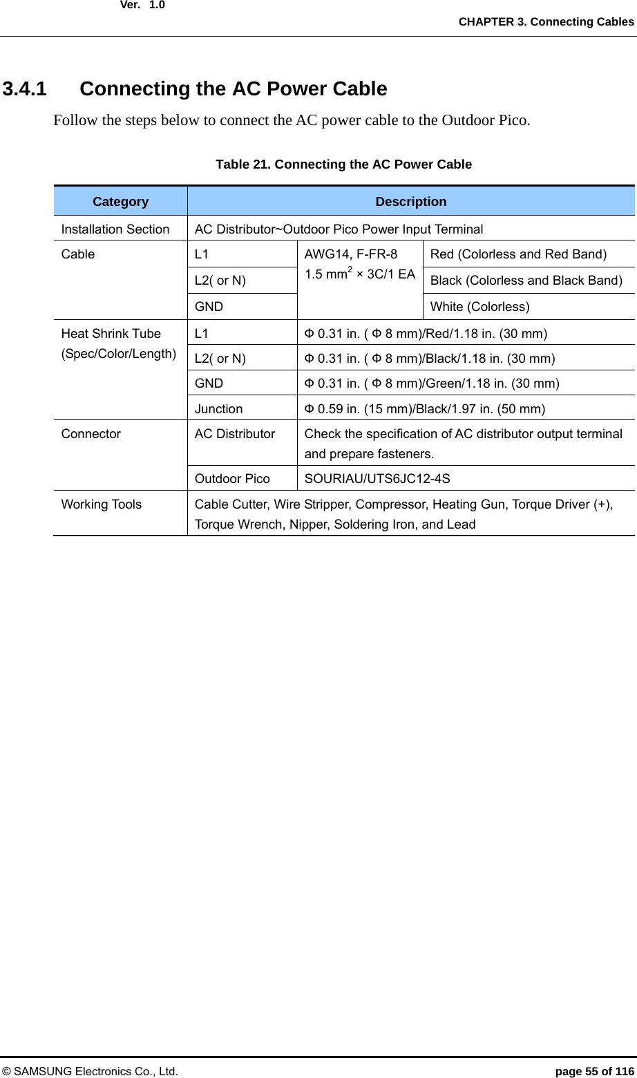
![Ver. CHAPTER 3. Connecting Cables © SAMSUNG Electronics Co., Ltd. page 56 of 116 1.0 Table 22. Power Cable/Connector Pin Map Power Connector Pin No. Description Heat Shrink Tube 120 VAC 1 L1 Red 2 N.C - 3 N White GND GND Green 240 VAC 1 L1 Red 2 N.C - 3 L2 Black GND GND Green AC Power cable In case of using AC power cable (AWG 14, F-FR-8 1.5 mm2 × 3C), it is applicable up to 721.8 ft (220 m). When the distance is 721.8 ft (220 m), followings should be considered. - Do not rapid ON/OFF (within one second): The voltage loss value caused by the cable resistance, and the Outdoor Pico could be damaged by the counter electromotive force caused by the cable inductance. - Do not use the power cables linked: Using the power cables linked each other, the loss will be increased. - For the length of the AC power cable, follow the safety regulation of the installation site. 1GND GND3 31[Cable-side Connector: UTS6JC12-4S] [System-side Connector: UTG012-4P]](https://usermanual.wiki/Samsung-Electronics-Co/SLS-BP00AK/User-Guide-2282928-Page-56.png)
![Ver. CHAPTER 3. Connecting Cables © SAMSUNG Electronics Co., Ltd. page 58 of 116 1.0Figure 22. Connecting the Outdoor Pico Power Cable (1) AC Distributor (120~240 VAC) 1) Install a power cable from the AC distributor to the power input port (120-240 VAC) of the Outdoor Pico. 2) Assemble a connector to the end of power cable (Outdoor Pico-side). Power Cable (AWG14, F-FR-8 1.5 mm2 × 3C) [Outdoor Pico] Power ConnectorPower CablePower Input Port (120~240 VAC)](https://usermanual.wiki/Samsung-Electronics-Co/SLS-BP00AK/User-Guide-2282928-Page-58.png)
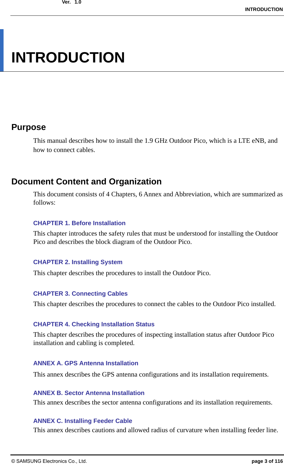
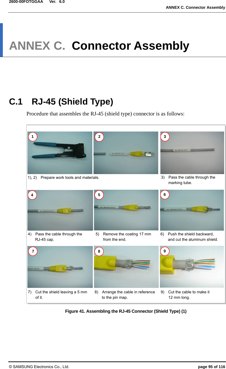
![Ver. CHAPTER 3. Connecting Cables © SAMSUNG Electronics Co., Ltd. page 60 of 116 1.03.5 External Interface Construction 3.5.1 Backhaul Cable Connection Follow the steps below to connect the backhaul cable (copper type) to the Outdoor Pico. Checking Backhaul Cable Connection Type The optic type and copper type have different parts and installation methods so prepare installation after checking the type with a service provider. Table 23. Table 3.6 Backhaul Cable Connection (Copper Type) Category Description Installation Section Switch or Router~Outdoor Pico_Backhaul (BH_ETH) Port Cable S-FTP, Cat.5e or Cat.6, 4Pair, #24/for Outdoor Connector Switch or Router RJ-45 (Shield Type) Outdoor Pico Harting 0945 145 1560, RJ-45 Working Tools LAN Tool, LAN Tester, Nipper, Wire Stripper, and Cable Cutter Table 24. Table 3.7 Backhaul Cable (Copper Type)/Connector Pin Map Pin No. 10 Base-T/100 Base-TX 1000 Base-T Color Pair No.1 Output signal positive BI Data 2 positive Orange/White 2 2 Output signal negative BI Data 2 negative Orange 2 3 Input signal positive BI Data 3 positive Green/White 3 4 N.C BI Data 1 positive Blue 1 5 N.C BI Data 1 negative Blue/White 1 6 Input signal negative BI Data 3 negative Green 3 7 N.C BI Data 4 positive Brown/White 4 8 N.C BI Data 4 negative Brown 4 [Cable-side Connector: Harting 0945 145 1560]1[System-side Connector: Harting 0945 245 1102 001] 8](https://usermanual.wiki/Samsung-Electronics-Co/SLS-BP00AK/User-Guide-2282928-Page-60.png)
![Ver. CHAPTER 3. Connecting Cables © SAMSUNG Electronics Co., Ltd. page 62 of 116 1.0 Figure 24. Backhaul Cable Connection_Copper Type Switch or Router 1) Install a backhaul cable from the switch (or router) to the backhaul port (BH_ETH) of the Outdoor Pico. 2) Connect the connector of a backhaul cable to the backhaul port (BH_ETH) of the Outdoor Pico. Backhaul Cable (S-FTP, Cat.5e or Cat.6, 4Pair, #24/Outdoor Type) [Outdoor Pico] Backhaul Connector (Copper Type) Backhaul Cable (Copper Type) Backhaul Por (Copper Type: BH_ETH)](https://usermanual.wiki/Samsung-Electronics-Co/SLS-BP00AK/User-Guide-2282928-Page-62.png)
![Ver. CHAPTER 3. Connecting Cables © SAMSUNG Electronics Co., Ltd. page 66 of 116 1.0GPS Cable Configuration The configuration of GPS cable is shown in the figure below. Figure 25. GPS Cable Configuration 1/2 in. Coaxial Cable (LDF4-50A or equivalent) [Line Amplifier][GPS Antenna] 1/2 inch Coaxial cable (Amplifier~GPS Antenna/Max. 32.80 ft,10 m) [Outdoor Pico]](https://usermanual.wiki/Samsung-Electronics-Co/SLS-BP00AK/User-Guide-2282928-Page-66.png)
![Ver. CHAPTER 3. Connecting Cables © SAMSUNG Electronics Co., Ltd. page 67 of 116 1.0 Figure 26. GPS Cable Connection (1) [GPS Antenna] 1) Install a GPS cable (LMR-400) from the GPS port of the Outdoor Pico to the GPS antenna. 2) Assemble the connector to the GPS cable. - Outdoor Pico-side Connector: N Type-Male - GPS Antenna-side Connector: N Type-Male 3) Connect the N type male connector assembled to the end of the GPS cable to the GPS port of the Outdoor Pico. 1/2 in. Coaxial Cable (LDF4-50A or equivalent) [Outdoor Pico] N Type-Male ConnectorGPS CableGPS Port](https://usermanual.wiki/Samsung-Electronics-Co/SLS-BP00AK/User-Guide-2282928-Page-67.png)
![Ver. CHAPTER 3. Connecting Cables © SAMSUNG Electronics Co., Ltd. page 69 of 116 1.0 Figure 28. GPS Cable Connection (3) 7) Connect the N type-male connector (assembled to the end of GPS cable) to the GPS antenna port. 1/2 in. Coaxial Cable (LDF4-50A or equivalent) [GPS Antenna][Outdoor Pico] 1/2 in. Coaxial Cable (LDF4-50A or equivalent) GPS 안테나 N Type-Female PortClampHeat Shrink Tube(Jelly Type)Clamp fixing Screw GPS 안테나 Fixing Pipe N Type-Male Connector](https://usermanual.wiki/Samsung-Electronics-Co/SLS-BP00AK/User-Guide-2282928-Page-69.png)
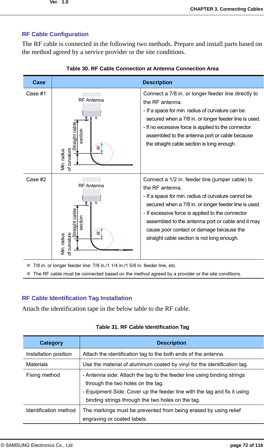
![Ver. CHAPTER 3. Connecting Cables © SAMSUNG Electronics Co., Ltd. page 73 of 116 1.0 RF Cable Connection Follow the steps below to connect the cable between Outdoor Pico and RF antenna. Figure 29. RF Cable Connection (1) RF Antenna RF Cable (1/2 in. Feeder Line) [Outdoor Pico] 1) Connect the connectors to the RF ports (N type-female) at the bottom of Outdoor Pico. 2) Assemble a connector at the end of the RF cable. (The specifications of the antenna and supplier-specific connector, and the tightening method are subject to change.) - Outdoor Pico-side Connector: N Type-Male - RF Antenna-side Connector: N Type-Male 3) Connect the connector assembled at the end of the RF cable (Outdoor Pico-side) to the RF antenna port of the Outdoor Pico. N Type-Male ConnectorRF CableRF Antenna PortHeat Shrink Tube](https://usermanual.wiki/Samsung-Electronics-Co/SLS-BP00AK/User-Guide-2282928-Page-73.png)
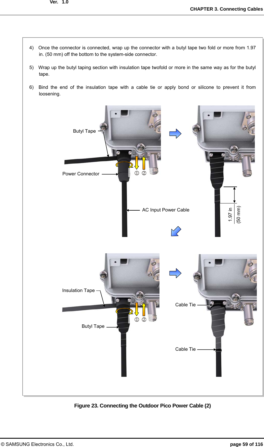
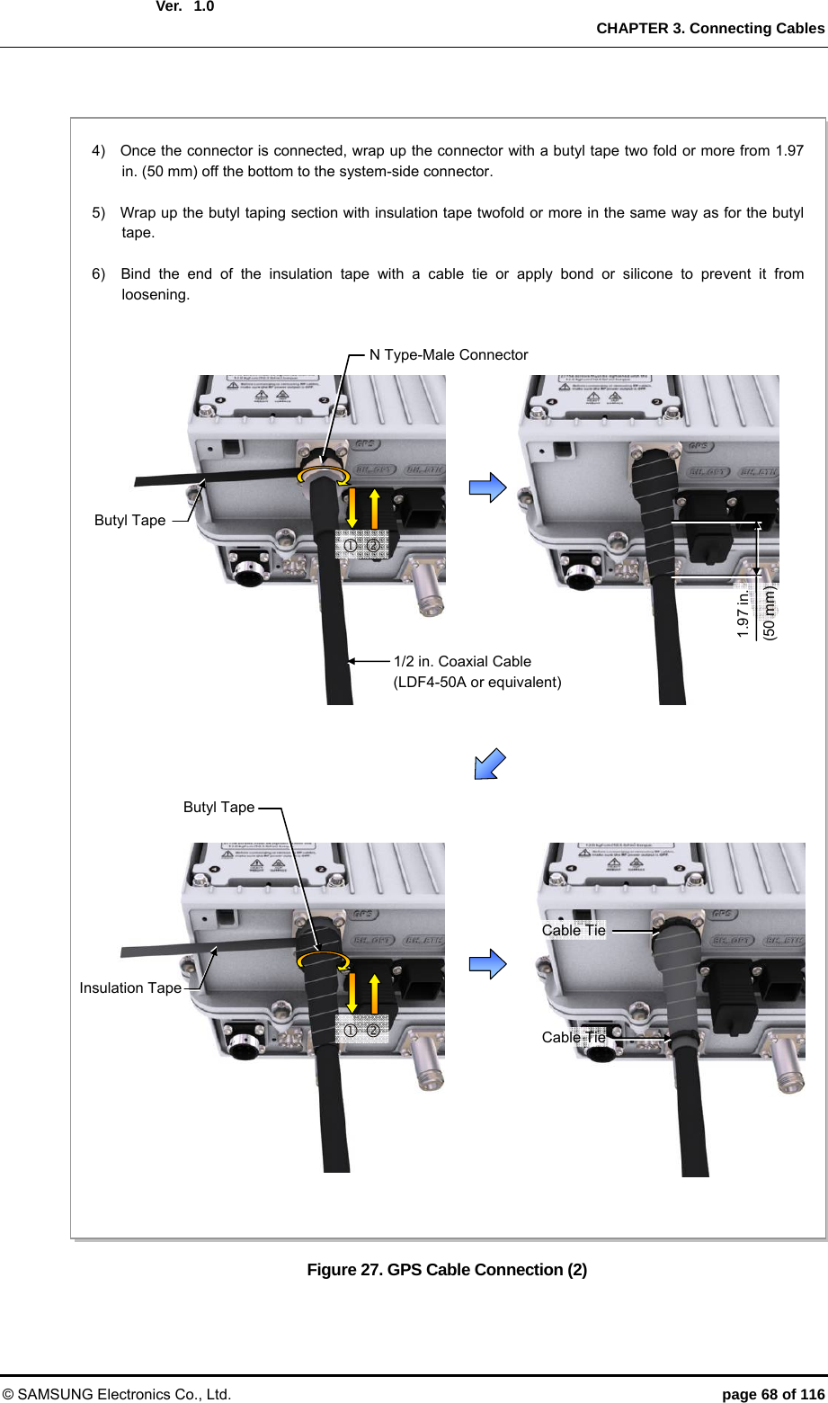
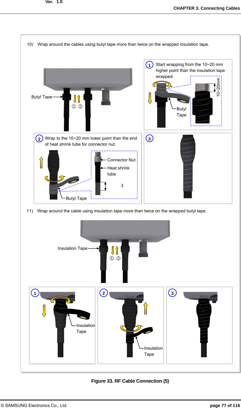
![Ver. CHAPTER 3. Connecting Cables © SAMSUNG Electronics Co., Ltd. page 74 of 116 1.0 Figure 30. RF Cable Connection (2) (1) Starting and Ending points of Butyl tape Starting and Ending points of Insulation Tape [Mid-point between (1) and (2)] (2) Top side of Connector Nut 4) After connecting a connector, wrap the cable from the system-side connector using insulation tape more than twice so that the metal parts of connection parts are not shown. Insulation Tape5) Wrap around the cables using butyl tape more than twice on the wrapped insulation tape. Butyl Tape2 3Insulation Tape 1 Insulation Tape 2 Butyl Tape 1Butyl Tape 10~20mm Start wrapping from the 10~20 mm higher point than the insulation tape wrapped. Wrap to the 10~20 mm lower point than the end of heat shrink tube for connector nut. Heat shrink tube Connector Nut 10[Bottom](https://usermanual.wiki/Samsung-Electronics-Co/SLS-BP00AK/User-Guide-2282928-Page-74.png)
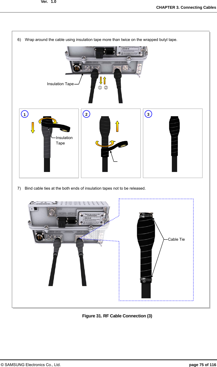
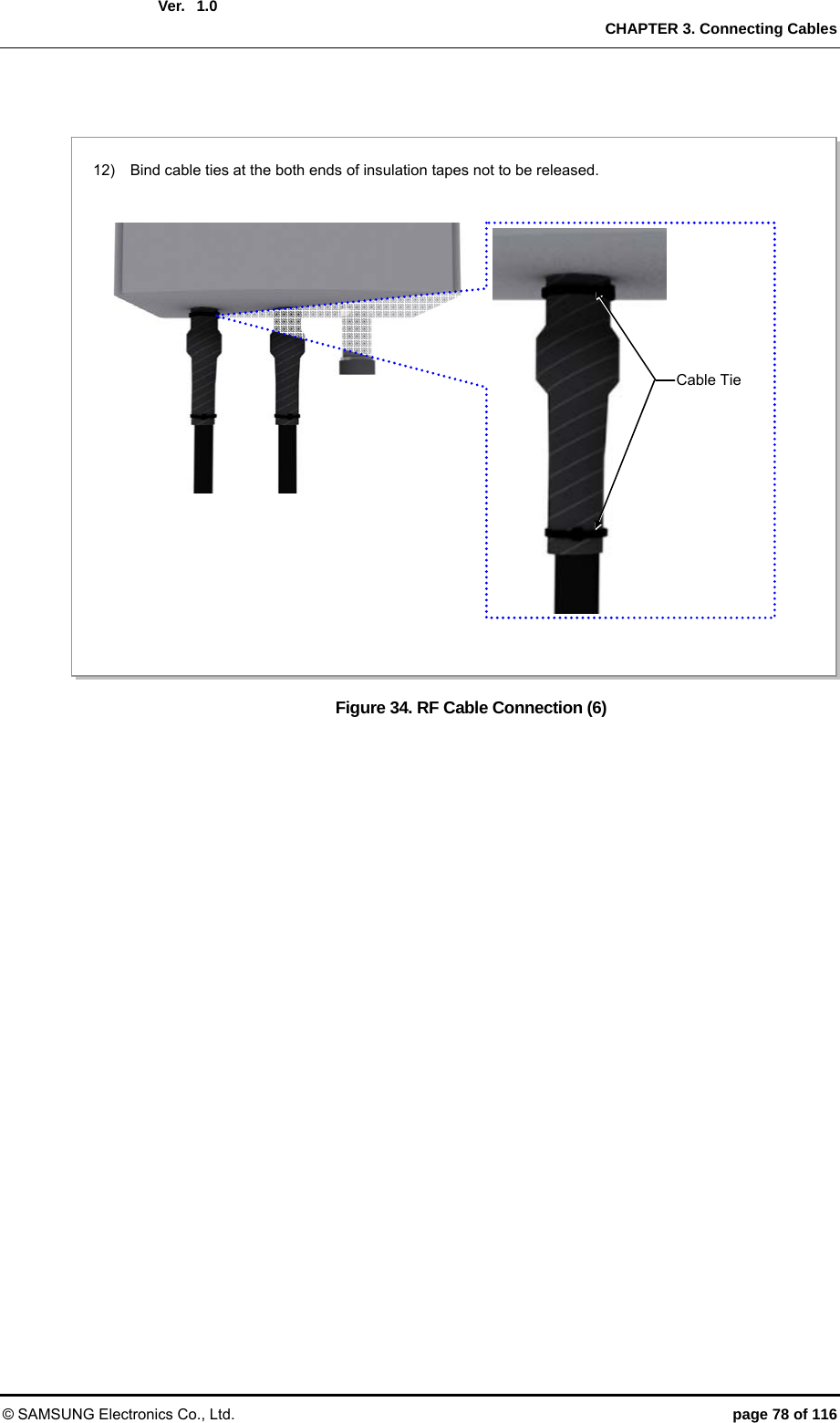
![Ver. CHAPTER 3. Connecting Cables © SAMSUNG Electronics Co., Ltd. page 76 of 116 1.0 Figure 32. RF Cable Connection (4) RF Antenna 8) Connect the connector (assembled to the end of the cable on the RF antenna side) to the RF antenna port. RF Antenna Input Port Heat Shrink Tube(Jelly Type) Din Type-Male Connector RF Cable 9) After connecting a connector, wrap the cable from the system-side connector using insulation tape more than twice so that the metal parts of connection parts are not shown. Insulation Tape(1) Starting and Ending points of Butyl tape Starting and Ending points of Insulation Tape [Mid-point between (1) and (2)] (2) Top side of Connector Nut 23Insulation Tape 1Insulation Tape](https://usermanual.wiki/Samsung-Electronics-Co/SLS-BP00AK/User-Guide-2282928-Page-76.png)
![Ver. ANNEX A. GPS Antenna Installation © SAMSUNG Electronics Co., Ltd. page 90 of 116 2600-00FOTGGAA 6.0Wall Figure 39. GPS Antennal Installation (Wall) GPS Antenna Wall Fixing Pipe [Ф 1~1.46 in.(25~37 mm)] GPS AntennaGPS Antenna Wall Fixing Clamp Assembly ≒ Min. 19.68 in.(500 mm )](https://usermanual.wiki/Samsung-Electronics-Co/SLS-BP00AK/User-Guide-2282928-Page-90.png)
![Ver. ANNEX A. GPS Antenna Installation © SAMSUNG Electronics Co., Ltd. page 91 of 116 2600-00FOTGGAA 6.0 Floor Figure 40. GPS Antennal Installation (Floor) GPS Antenna Floor Fixing Pipe [Ф 1~1.46 in.(25~37 mm)] GPS AntennaM10 Anchor Bolt Assembly≒ Min. 19.69 in.(500 mm) Concrete Block≒ Min. 15.74 in.(400 mm) ≒ Min. 9.84 in.(250 mm)](https://usermanual.wiki/Samsung-Electronics-Co/SLS-BP00AK/User-Guide-2282928-Page-91.png)
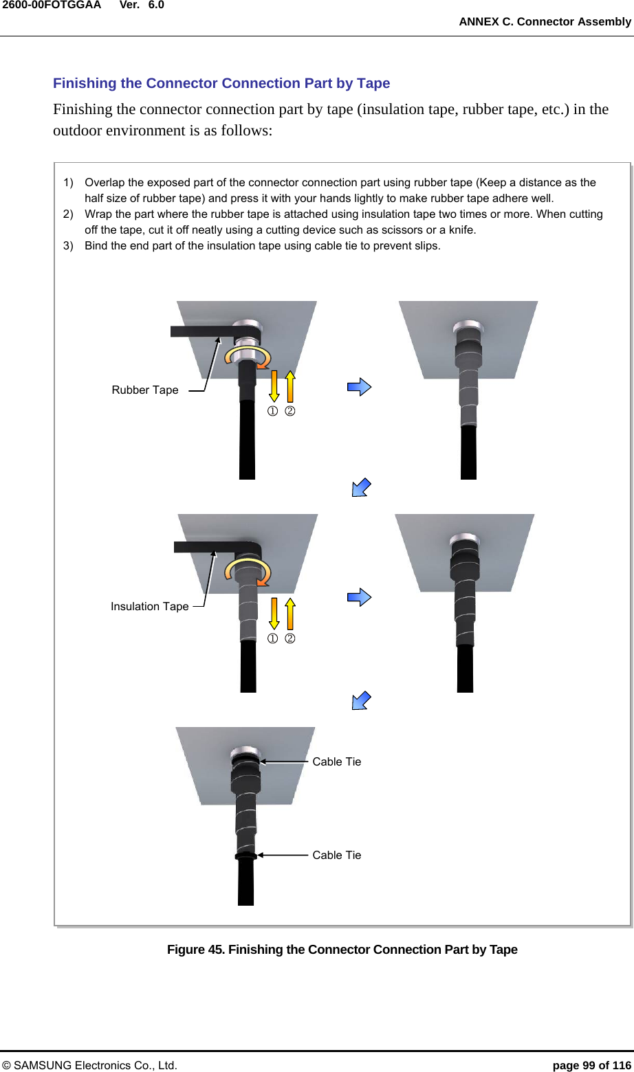
![Ver. ANNEX C. Connector Assembly © SAMSUNG Electronics Co., Ltd. page 98 of 116 2600-00FOTGGAA 6.0C.3 Finishing the Connector Connection Part by Tape Check Items for Finishing the Connector Connection Part Check following items before finishing the connector connection part by tape. Figure 44. Check Items for Finishing the Connector Connection Part * Wrapping only the metal part of connector connection using insulation tape XO * Wrapping the tape with overlapping Starting and Ending points of Insulation Tape [Mid-point between (1) and (2)]Wrap the tape with the half of the tape width is overlapped. (For both insulation tape and butyl tape) Tape WidthOverlap area of tape(1) Starting and Ending pointsof Butyl tape (2) Top side of Connector Nut](https://usermanual.wiki/Samsung-Electronics-Co/SLS-BP00AK/User-Guide-2282928-Page-98.png)
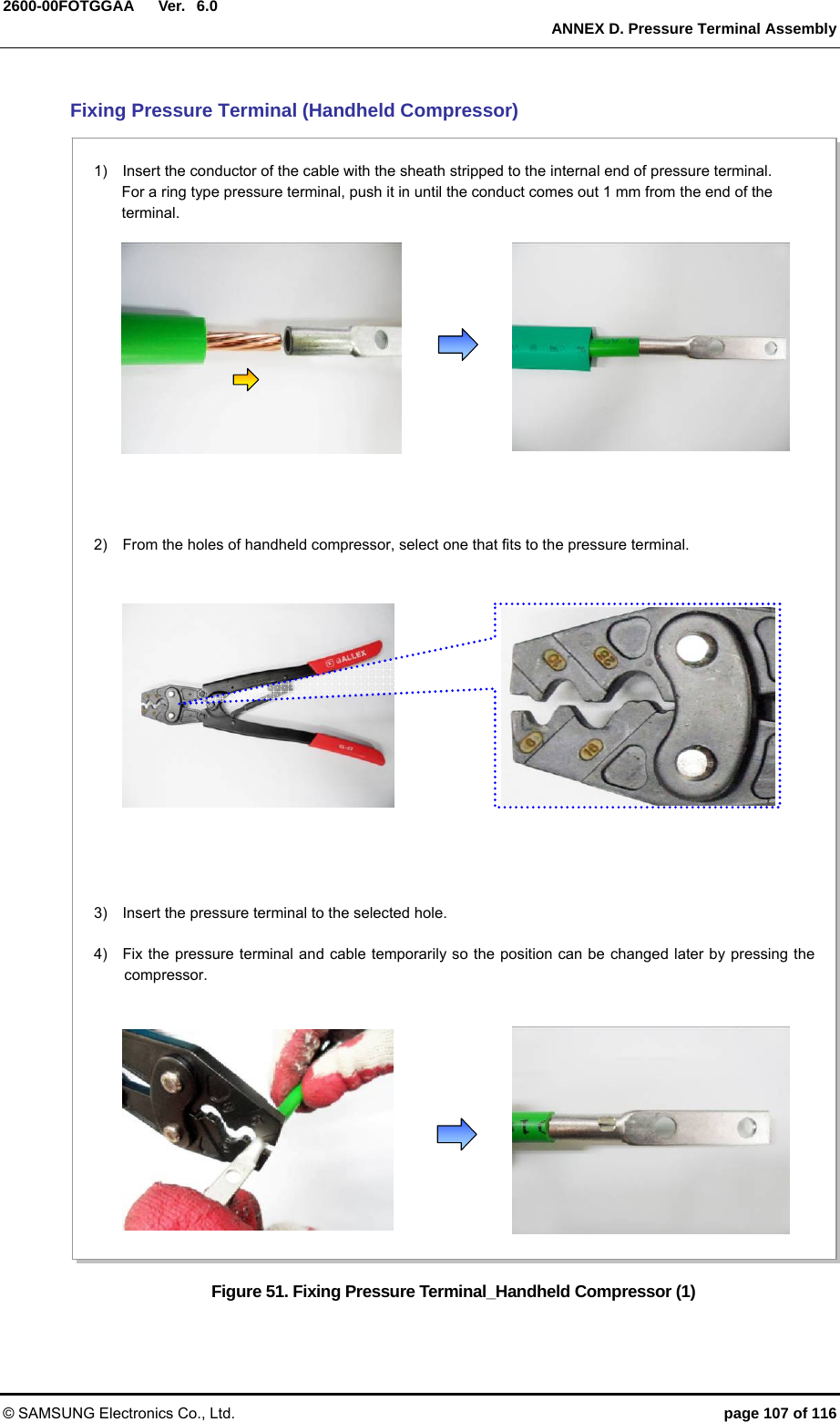
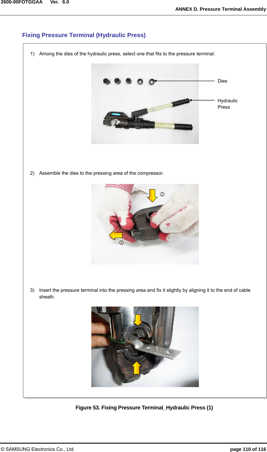
![Ver. ANNEX D. Pressure Terminal Assembly © SAMSUNG Electronics Co., Ltd. page 100 of 116 2600-00FOTGGAA 6.0ANNEX D. Pressure Terminal Assembly D.1 Preparations The followings must be prepared to connect a pressure terminal to a cable. Figure 46. Preparations [Cable Cutter] [Wire Stripper] [Handheld Compressor] [Hydraulic Press] [Heating Gun] [Marking Pen] [Cutter Blade] [Steel Ruler] [Scissors] [Cable] [Pressure Terminal][Heat Shrink Tube]](https://usermanual.wiki/Samsung-Electronics-Co/SLS-BP00AK/User-Guide-2282928-Page-100.png)
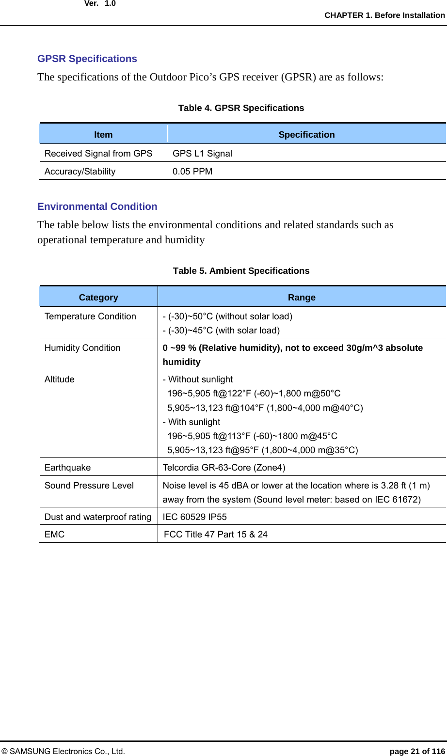
![Ver. ANNEX D. Pressure Terminal Assembly © SAMSUNG Electronics Co., Ltd. page 101 of 116 2600-00FOTGGAA 6.0 D.2 Pressure Reference Table The pressure reference table used to assemble a pressure terminal to a cable is shown below. Table 38. Pressure Reference Table for Pressure Terminal Category Copper tube length of a pressure terminal Number of pressure pointsmm In. Hand 11 mm or less 0.43 in. 1 Hand 12~15 mm 0.47~0.59 in. 2 Hand 16~23 mm 0.63~0.91 in. 3 Hand 24~32 mm 0.94~1.26 in. 4 Hand 33 mm or more 1.3 in. or more 5 Hydraulic 30 mm or less 1.18 in. or less 2 Hydraulic 31~47 mm 1.22~1.85 in. 3 Hydraulic 48~63 mm 1.89~2.48 in. 4 Hydraulic 64 mm or more 2.52 in. or more 5 Figure 47. Pressure Reference Drawing (Handheld Compressor) [1-spot] [2-spot] [3-spot] [4-spot] Unit: in. (mm)0.43 (11) 0.18 (4.5) 0.47 (12) 0.59 (15) 0.63 (16) 0.91 (23) 0.94 in. (24) 1.26 (32) 0.63 (16) 0.18 (4.5) Copper Tube Starting Middle of Copper Tube Arbitrary Fixing Reference Points](https://usermanual.wiki/Samsung-Electronics-Co/SLS-BP00AK/User-Guide-2282928-Page-101.png)
![Ver. ANNEX D. Pressure Terminal Assembly © SAMSUNG Electronics Co., Ltd. page 102 of 116 2600-00FOTGGAA 6.0 Figure 48. Pressure Reference Drawing (Hydraulic Press) Unit: in. (mm)[2-spot] [3-spot] [4-spot] 1.18 (30) [4-spot] Copper Tube Starting Duplicate Pressure Arbitrary Fixing Reference Points 0.53 (13.5) 1.22 (31) 0.53 (13.5) 1.22 (31) 1.85 (47) 1.89 (48) 2.48 (63) 2.52 (64)](https://usermanual.wiki/Samsung-Electronics-Co/SLS-BP00AK/User-Guide-2282928-Page-102.png)
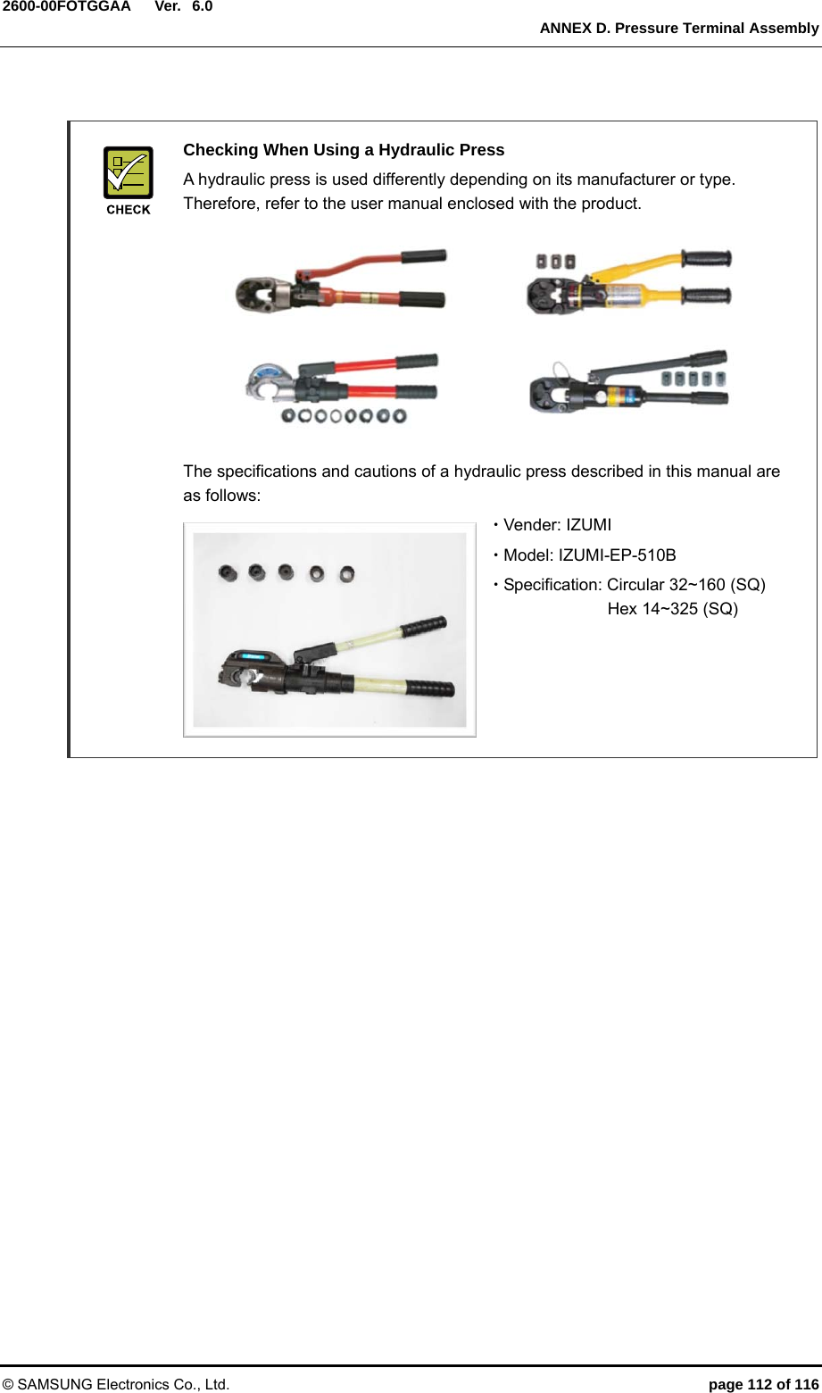
![Ver. ANNEX D. Pressure Terminal Assembly © SAMSUNG Electronics Co., Ltd. page 106 of 116 2600-00FOTGGAA 6.0 Checking When Using A Wire Stripper A wire stripper is used differently depending on its manufacturer or type. Therefore, refer to the user manual enclosed with the product. The specifications and cautions of a wire stripper described in this manual are as follows: Vender: Weidmuller Model: Weidmuller-AM25 (Order No-9001080000) Specifications: For outer diameter 6-24 mm PVC sheath Up to 4.5 mm sheath cutting depth - To prevent the cutter blade of a wire stripper from touching the cable conductor, adjust the length of cutter blade by checking the cable sheath thickness. - Make sure that the cutter blade goes into the cable sheath completely. - Rotate the wire stripper perpendicularly to the cable. [X] [O]](https://usermanual.wiki/Samsung-Electronics-Co/SLS-BP00AK/User-Guide-2282928-Page-106.png)