Samsung Electronics Co SLS-BP00AK Outdoor Pico eNB User Manual
Samsung Electronics Co Ltd Outdoor Pico eNB
User Manual

Ver.
1.0
LTE 1.9 GHz Outdoor Pico eNB
Installation Manual

Ver.
1.0
COPYRIGHT
This manual is proprietary to SAMSUNG Electronics Co., Ltd. and is protected by copyright.
No information contained herein may be copied, translated, transcribed or duplicated for any commercial
purposes or disclosed to the third party in any form without the prior written consent of SAMSUNG Electronics
Co., Ltd.
TRADEMARKS
Product names mentioned in this manual may be trademarks and/or registered trademarks of their respective
companies.
This manual should be read and used as a guideline for properly installing and operating the product.
All reasonable care has been made to ensure that this document is accurate. If you have any comments on
this manual, please contact our documentation centre at the following homepage:
Homepage: http://www.samsungdocs.com
©2014 SAMSUNG Electronics Co., Ltd. All rights reserved.

Ver.
INTRODUCTION
© SAMSUNG Electronics Co., Ltd. page 3 of 116
1.0
INTRODUCTION
Purpose
This manual describes how to install the 1.9 GHz Outdoor Pico, which is a LTE eNB, and
how to connect cables.
Document Content and Organization
This document consists of 4 Chapters, 6 Annex and Abbreviation, which are summarized as
follows:
CHAPTER 1. Before Installation
This chapter introduces the safety rules that must be understood for installing the Outdoor
Pico and describes the block diagram of the Outdoor Pico.
CHAPTER 2. Installing System
This chapter describes the procedures to install the Outdoor Pico.
CHAPTER 3. Connecting Cables
This chapter describes the procedures to connect the cables to the Outdoor Pico installed.
CHAPTER 4. Checking Installation Status
This chapter describes the procedures of inspecting installation status after Outdoor Pico
installation and cabling is completed.
ANNEX A. GPS Antenna Installation
This annex describes the GPS antenna configurations and its installation requirements.
ANNEX B. Sector Antenna Installation
This annex describes the sector antenna configurations and its installation requirements.
ANNEX C. Installing Feeder Cable
This annex describes cautions and allowed radius of curvature when installing feeder line.
Ver.
INTRODUCTION
© SAMSUNG Electronics Co., Ltd. page 4 of 116
1.0
ANNEX D. Connector Assembly
This annex describes the procedure of assembling the connector.
ANNEX E. Pressure Terminal Assembly
This annex describes the procedure of assembling the pressure terminal.
ANNEX F. Standard Torque
This annex describes the standard torque when tightening the bolt.
ABBREVIATION
Describes the acronyms used in this manual.
Conventions
The following types of paragraphs contain special information that must be carefully read
and thoroughly understood. Such information may or may not be enclosed in a rectangular
box, separating it from the main text, but is always preceded by an icon and/or a bold title.
WARNING
Provides information or instructions that the reader should follow in order to avoid
personal injury or fatality.
CAUTION
Provides information or instructions that the reader should follow in order to avoid
a service failure or damage to the system.
CHECKPOINT
Provides the operator with checkpoints for stable system operation.
NOTE
Indicates additional information as a reference.

Ver.
INTRODUCTION
© SAMSUNG Electronics Co., Ltd. page 5 of 116
1.0
Product Safety Information
WARNING
This product contains chemicals known to the State of California to cause cancer and
reproductive toxicity.
CALIFORNIA USA ONLY
This Perchlorate warning applies only to primary CR (Manganese Dioxide) Lithium coin cells in
the product sold or distributed ONLY in California USA
"Perchlorate Material - special handling may apply,
See www.dtsc.ca.gov/hazardouswaste/perchlorate. "
Installation Regulation
Installation shall be in accordance with the applicable parts of Chapter 8 of ANSI/NFPA 70 (for
USA).
The installation regulation should be checked for each country. (It can be different from each
other.)
Revision History
VERSION DATE OF ISSUE REMARKS
1.0 05. 2014. First Version
Ver.
SAFETY CONCERNS
© SAMSUNG Electronics Co., Ltd. page 6 of 116
1.0
SAFETY CONCERNS
The purpose of the Safety Concerns section is to ensure the safety of users and prevent
property damage. Please read this document carefully for proper use.
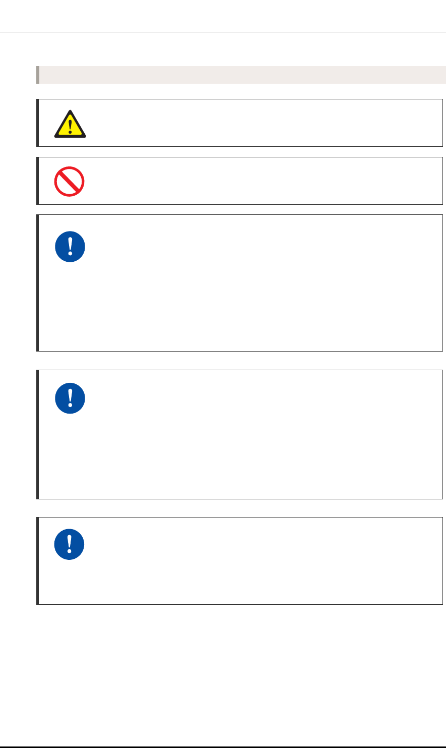
Symbols
Caution
Indication of a general caution
Restriction
Indication for prohibiting an action for a product
Instruction
Indication for commanding a specifically required action
Ver.
SAFETY CONCERNS
© SAMSUNG Electronics Co., Ltd. page 7 of 116
1.0
Power and Grounding
Cautions When Using Insulation Tester
Pay attention to the followings to prevent any personal injury caused by an
electric shock when using an insulation tester.
- Make sure the polarity is correct when connecting the Earth COM (black) and
AC.V (red) lead lines. And do not touch the connected probes inspecting part of
the lead line) with a hand and avoid body contact.
- Avoid body contact to the system when measuring an insulation resistance.
Watches, rings, and other metallic accessories
Do not wear accessories such as watches and rings in order to prevent electrical
short-circuit.
Power Switch Off
Make sure the power switch of power supplier is off when installing the system.
Installing the system with power switch on may cause system damage or fatal
human injury when cables are not correctly connected.
Connecting Ground Cable
When connecting the cables, always connect the ground cable first. If worker
contacts the equipment, connect a cable or perform maintenance without
connecting the ground cable, the system can be damaged or a worker may be
injured due to static electricity and short circuit.
Turning Off the Circuit Breaker before Connecting the Power Cable
Since power is applied to the system where the power cable is connected by
manipulating the circuit breaker of the AC distributor, be sure to check the AC
distributor’s breaker and the system switch are turned off (open) before
connecting the power cable to the power connector. If the system is installed
while the circuit breaker and system switch is on, the worker may be critically
injured as soon as the cable is connected in the wrong way.
WARNING
Ver.
SAFETY CONCERNS
© SAMSUNG Electronics Co., Ltd. page 8 of 116
1.0
Installation
Protection gloves and goggles
Make sure that worker wears protection gloves and goggles to prevent damage
from debris while drilling holes in a wall or ceiling.
Power and Feeder line
Cautions while Cleaning Power Supply
While cleaning the power supply device, take caution that the device does not
come in contact with alien bodies that may cause power failure.
Precautions While Measuring Insulation Resistance
Observe the followings to prevent any system damage when measuring insulation
resistance because there is a very high voltage.
- Before measuring insulation resistance, disconnect all the cables connected to
the system.
- Do not measure insulation resistance when power is on.
- Do not measure insulation resistance at any other positions such as system
internal units or parts other than the targeted insulation resistance measuring
points.
CAUTION
Ver.
SAFETY CONCERNS
© SAMSUNG Electronics Co., Ltd. page 9 of 116
1.0
System Grounding Method
Ground bar for lightning protector/power/communication must be isolated from
each other. These three ground bars can be grounded as the isolation grounding
method, or branched from ground mesh buried in the underground as common
grounding method.
Precautions When Connecting Power Cable
To secure rainproof performance of a cable gland, min. 11.81 in. (300 mm)
straight section must be maintained. Here, the radius of curvature must be
considered according to the cable specification.
When Using Power Cables
- When handling the power cable, ensure the power switch of a rectifier is turned
off to prevent the risk from the power cable and electric short-circuit of related
cables.
- Because a power accident may occur when fixing parts get loosened, make
sure that fasteners to fix the power cable should be firmly fastened.
- The resistance temperature of power cable should be higher than 194°F (90°C).
AC Power cable
In case of using AC power cable (AWG 14, F-FR-8 1.5 mm2 × 3C), it is applicable up
to 721.8 ft (220 m). When the distance is 721.8 ft (220 m), followings should be
considered.
- Do not rapid ON/OFF (within one second): The voltage loss value caused by the
cable resistance, and the Outdoor Pico could be damaged by the counter
electromotive force caused by the cable inductance.
- Do not use the power cables linked: Using the power cables linked each other,
the loss will be increased.
- For the length of the AC power cable, follow the safety regulation of the
installation site.
Cautions When Connecting AC Power
When connecting the AC power cable to the L1-GND-L2, check the polarity of
each phase at the L1-GND-L2 single-phase connection area of AC power
distributor to ensure that correct polarity is connected to the L1-GND-L2 of the
system's input end. Check if the 120V-240 V between L1 and L2 is within the
allowable range (with tolerance of +/-10%).
Ver.
SAFETY CONCERNS
© SAMSUNG Electronics Co., Ltd. page 10 of 116
1.0
Connection of Feeder Cable Connector
Connecting the feeder cable connector is critical process, so the qualified workers
who finished the related education should perform.
Installing the Antenna
When you install the antenna, the antenna must be within the protective angle
(left/right side 45° each from the central axis) to prevent the antenna from
lightning damage.
Cautions on the Min. Radius of Curvature of GPS Cable and Its Length
Limitation
If the GPS cable min. radius of curvature or its length limitation is violated, a GPS
signal may not be received seamlessly and it may cause abnormal system
operation. Therefore, the min. radius of curvature and length limitation of a GPS
cable proposed in the above table must be observed.
Checking VSWR for Minimum Cable Bend Radius and Length of RF Cable
If the VSWR value for minimum cable bend radius and length of RF cable is not
applied, system may not work properly because RF signals cannot transmit or
receive smoothly. So, the VSWR value for minimum cable bend radius and length
of RF cable must be checked and applied.
Cautions When Measuring VSWR
When measuring VSWR, if you open the antenna port when the transmission
output is not completely off, a spike signal may flow into the reception path, which
may cause damage to LNA. Make sure the transmission output is completely off
when measuring VSWR.
Cautions When Connecting Feeder Lines
If you install the feeder line which is connected to the system, it may damage the
system and cable connection. Therefore, it is recommended to install the feeder line
up to the system's input port before connecting the feeder line to the system.
Ver.
SAFETY CONCERNS
© SAMSUNG Electronics Co., Ltd. page 11 of 116
1.0
General Installation
When Cleaning the System
Be careful not to damage the cables when cleaning the system.
Do not Work by Yourself
Worker must not work alone in any key process.
Finishing the System Input/output Port and Cable Inlet
To prevent foreign substances, outdoor air and moisture from entering the system
input/output port and cable inlet (including cable gland and conduit), finish it as
follows:
- Unused inlet
Use the hole finishing materials including waterproof cap and rubber packing.
- Cable-installed Port and Cable Inlet
After cable installation, block any space in the inlet with tape, compressed
sponge, rubber packing, and silicon.
Checking Marking (horizontal/vertical) When Mounting the System on Wall
If you do the drilling or anchoring on a wall when the positions are not marked to
be horizontal or vertical, only limited range of tuning is allowed for leveling after
the system is mounted.
To mount the system on a wall, perform the leveling test by referring to ‘System
Leveling’ to check the positions are marked to be horizontal or vertical before
drilling. If the result shows they are not horizontal or vertical, modify the marking
positions.
Considerations when Cutting the Cable after Installation
When cutting the cable after installation, make sure that the connector is
disconnected. Installation of the cable with the connector connected to the system
may cause contact failure or damage to the connector assembled to the system
and the cable due to cable tension or the operator’s mistakes.
Ver.
SAFETY CONCERNS
© SAMSUNG Electronics Co., Ltd. page 12 of 116
1.0
Management of Unused Ports
Cover the unused ports (conduit, cable gland, etc.) with waterproof cap (sealing
cap) to prevent infiltration of foreign material such as dust, moisture, or bug.
Installing the Concrete Block
A concrete block should be installed that satisfies the specification regarding size
and strength. When installing the concrete block, and before forming the
concrete, steel reinforcement bars should be arranged in a mesh layout at
100 mm intervals before forming the concrete. (Either an anchor bolt assembly or
a concrete anchor can be used.)
Installation Location of ‘System’ the Outdoor pico eNB
When you install this equipment in the field, it should be installed in a Restricted
Access Location
California USA Only
This Perchlorate warning applies only to primary CR (Manganese Dioxide)
Lithium coin cells in the product sold or distributed ONLY in California USA
‘Perchlorate Material-special handling may apply, See
www.dtsc.ca.gov/hazardouswaste/perchlorate.’

Ver.
TABLE OF CONTENTS
© SAMSUNG Electronics Co., Ltd. page 13 of 116
1.0
TABLE OF CONTENTS
INTRODUCTION 3
Purpose ................................................................................................................................................. 3
Document Content and Organization.................................................................................................... 3
Conventions ........................................................................................................................................... 4
Product Safety Information .................................................................................................................... 5
Installation Regulation ........................................................................................................................... 5
Revision History ..................................................................................................................................... 5
SAFETY CONCERNS 6
Symbols ................................................................................................................................................. 6
WARNING ............................................................................................................................................. 7
CAUTION .............................................................................................................................................. 8
California USA Only ............................................................................................................................. 12
CHAPTER 1. Before Installation 18
1.1 System Configuration ............................................................................................................. 18
1.2 Specifications ......................................................................................................................... 20
1.3 Cautions for Installation ......................................................................................................... 22
1.4 Installation Tools ..................................................................................................................... 24
CHAPTER 2. Installing System 25
2.1 Installing the Outdoor Pico .................................................................................................... 25
2.2 Foundation Work .................................................................................................................... 26
2.2.1 System Arrangement .............................................................................................................. 26
2.2.2 Marking and Drilling ................................................................................................................. 28
2.3 Unpacking and Transporting ................................................................................................. 30
2.3.1 Bringing in Items ...................................................................................................................... 30
2.3.2 Unpacking Items ...................................................................................................................... 30
2.4 Fixing System ......................................................................................................................... 31
2.4.1 Assembling Tightening Parts for Outdoor Pico ....................................................................... 33
2.4.2 Fixing the Outdoor Pico(Wall Type) ........................................................................................ 34

Ver.
TABLE OF CONTENTS
© SAMSUNG Electronics Co., Ltd. page 14 of 116
1.0
2.4.3 Fixing the Outdoor Pico (Pole Type) ....................................................................................... 36
2.5 System Leveling ...................................................................................................................... 40
2.6 Insulation Test ......................................................................................................................... 42
CHAPTER 3. Connecting Cables 44
3.1 Work Flow for Cabling ............................................................................................................ 44
3.2 Cabling ..................................................................................................................................... 49
3.3 Grounding ................................................................................................................................ 51
3.3.1 Grounding the Outdoor Pico ................................................................................................... 52
3.4 Power Cabling ......................................................................................................................... 54
3.4.1 Connecting the AC Power Cable ............................................................................................ 55
3.5 External Interface Construction ............................................................................................. 60
3.5.1 Backhaul Cable Connection .................................................................................................... 60
3.5.2 GPS Cable Connection ........................................................................................................... 63
3.5.3 RF Cable Connection .............................................................................................................. 70
CHAPTER 4. Checking Installation Status 79
4.1 Installation Checking Procedure ............................................................................................ 79
ANNEX A. GPS Antenna Installation 83
A.1 GPS Antenna System Configuration ..................................................................................... 83
A.1.1 GPS Antenna ........................................................................................................................... 84
A.1.2 Lightening Arrestor .................................................................................................................. 86
A.2 Interference Signal .................................................................................................................. 87
A.3 GPS Antenna Installation ........................................................................................................ 89
ANNEX B. Installing Feeder Cable 92
B.1 Cautions When Installing Feeder Cable ................................................................................ 92
ANNEX C. Connector Assembly 95
C.1 RJ-45 (Shield Type) ................................................................................................................. 95
C.2 RJ-45 (Normal Type) ................................................................................................................ 97
C.3 Finishing the Connector Connection Part by Tape .............................................................. 98
ANNEX D. Pressure Terminal Assembly 100
D.1 Preparations........................................................................................................................... 100

Ver.
TABLE OF CONTENTS
© SAMSUNG Electronics Co., Ltd. page 15 of 116
1.0
D.2 Pressure Reference Table .....................................................................................................101
D.3 Assembling Pressure Terminal ............................................................................................104
ANNEX E. Standard Torque 114
ABBREVIATION 115
LIST OF FIGURES
Figure 1. Outdoor Pico Configuration ......................................................................................... 18
Figure 2. External Interface of Outdoor Pico .............................................................................. 19
Figure 3. Procedure to Install the System .................................................................................. 25
Figure 4. Outdoor Pico Arrangement(Wall Type) ........................................................................ 26
Figure 5. Outdoor Pico Arrangement(Pole Type) ....................................................................... 27
Figure 6. System Marking-Wall Type ......................................................................................... 29
Figure 7. Assembling Tightening Parts for Installing Outdoor Pico ............................................. 33
Figure 8. Fixing Unit Mounting Bracket (Wall Type) ................................................................... 34
Figure 9. Fixing the Outdoor Pico (Wall Type) ............................................................................ 35
Figure 10. Fixing Unit Mounting Bracket and Pole Mounting Bracket ........................................ 37
Figure 11. Fixing the Outdoor Pico_Pole Type (1) ...................................................................... 38
Figure 12. Fixing the Outdoor Pico_Pole Type (2) ..................................................................... 39
Figure 13. Leveling Using a Level (Wall Type) ........................................................................... 41
Figure 14. Leveling Using a Level (Pole Type) ........................................................................... 41
Figure 15. Schematic Diagram for Insulation Test (Wall Type) ................................................... 43
Figure 16. Schematic Diagram for Insulation Test (Pole Type) .................................................. 43
Figure 17. Work Flow for System Cabling .................................................................................. 44
Figure 18. Detailed Cabling Procedure ...................................................................................... 45
Figure 19. Cabling Diagram ....................................................................................................... 49
Figure 20. Connection of the Outdoor Pico Ground Cable ......................................................... 53
Figure 21. Power Equipment Diagram ....................................................................................... 54
Figure 22. Connecting the Outdoor Pico Power Cable (1) ......................................................... 58
Figure 23. Connecting the Outdoor Pico Power Cable (2) ......................................................... 59
Figure 24. Backhaul Cable Connection_Copper Type ............................................................... 62
Figure 25. GPS Cable Configuration .......................................................................................... 66
Figure 26. GPS Cable Connection (1) ....................................................................................... 67
Figure 27. GPS Cable Connection (2) ....................................................................................... 68
Figure 28. GPS Cable Connection (3) ....................................................................................... 69
Figure 29. RF Cable Connection (1) .......................................................................................... 73

Ver.
TABLE OF CONTENTS
© SAMSUNG Electronics Co., Ltd. page 16 of 116
1.0
Figure 30. RF Cable Connection (2) ........................................................................................... 74
Figure 31. RF Cable Connection (3) ........................................................................................... 75
Figure 32. RF Cable Connection (4) ........................................................................................... 76
Figure 33. RF Cable Connection (5) ........................................................................................... 77
Figure 34. RF Cable Connection (6) ........................................................................................... 78
Figure 35. Installation Checking Procedure ................................................................................ 79
Figure 36. Example of a Common GPS Antenna System Configuration .................................... 83
Figure 37. Elevation Mask and Satellites .................................................................................... 84
Figure 38. GPS Antenna Installation ........................................................................................... 86
Figure 39. GPS Antennal Installation (Wall) ................................................................................ 90
Figure 40. GPS Antennal Installation (Floor) .............................................................................. 91
Figure 41. Assembling the RJ-45 Connector (Shield Type) (1) ................................................... 95
Figure 42. Assembling the RJ-45 Connector (Shield Type) (2) ................................................... 96
Figure 43. Assembling the RJ-45 Connector (Normal Type) ....................................................... 97
Figure 44. Check Items for Finishing the Connector Connection Part ........................................ 98
Figure 45. Finishing the Connector Connection Part by Tape ..................................................... 99
Figure 46. Preparations ............................................................................................................ 100
Figure 47. Pressure Reference Drawing (Handheld Compressor) ........................................... 101
Figure 48. Pressure Reference Drawing (Hydraulic Press) ...................................................... 102
Figure 49. Stripping Cable Sheath (1) ...................................................................................... 104
Figure 50. Stripping Cable Sheath (2) ...................................................................................... 105
Figure 51. Fixing Pressure Terminal_Handheld Compressor (1) .............................................. 107
Figure 52. Fixing Pressure Terminal_Handheld Compressor (2) .............................................. 108
Figure 53. Fixing Pressure Terminal_Hydraulic Press (1) ......................................................... 110
Figure 54. Fixing Pressure Terminal_Hydraulic Press (2) ......................................................... 111
Figure 55. Assembling Heat Shrink Tube ................................................................................. 113
LIST OF TABLES
Table 1. Key Specifications ......................................................................................................... 20
Table 2. Power Specifications ..................................................................................................... 20
Table 3. Dimensions and Weight ................................................................................................ 20
Table 4. GPSR Specifications ..................................................................................................... 21
Table 5. Ambient Specifications .................................................................................................. 21
Table 6. Basic Installation Tools .................................................................................................. 24
Table 7. Recommended Distances for System ........................................................................... 26
Table 8. Anchor Bolt Drill Bits and Hole Depth ............................................................................ 29
Table 9. Outdoor Pico Installation Tools and Torque Value ......................................................... 31
Table 10. Tightening Parts for Outdoor Pico ............................................................................... 32

Ver.
TABLE OF CONTENTS
© SAMSUNG Electronics Co., Ltd. page 17 of 116
1.0
Table 11. Tightening Parts and Tools for Installing Outdoor Pico ................................................ 33
Table 12. Unit Mounting Bracket Fixing Parts and Tool (Wall Type) ........................................... 34
Table 13. Outdoor Pico Fixing Parts and Tools (Wall Type) ........................................................ 35
Table 14. Unit/Pole Mounting Bracket Fixing Parts And Tool ...................................................... 36
Table 15. Outdoor Pico Fixing Parts and Tools (Pole Type) ....................................................... 38
Table 16. Leveling Using a Level ............................................................................................... 40
Table 17. Insulation Test............................................................................................................. 42
Table 18. Recommended Minimum Allowed Cable Bend Radius ............................................... 47
Table 19. Outdoor Pico Connection Cable ................................................................................. 50
Table 20. Grounding the Outdoor Pico ....................................................................................... 52
Table 21. Connecting the AC Power Cable ................................................................................ 55
Table 22. Power Cable/Connector Pin Map ............................................................................... 56
Table 23. Table 3.6 Backhaul Cable Connection (Copper Type) ............................................. 60
Table 24. Table 3.7 Backhaul Cable (Copper Type)/Connector Pin Map ................................. 60
Table 25. GPS Cable Connection .............................................................................................. 63
Table 26. GPS Cable Min. Radius of Curvature and Length Limitation ...................................... 63
Table 27. Identification Tag of GPS Cable .................................................................................. 65
Table 28. RF Cable Connection ................................................................................................. 70
Table 29. RF Cable Min. Radius of Curvature ............................................................................ 70
Table 30. RF Cable Connection at Antenna Connection Area .................................................... 72
Table 31. RF Cable Identification Tag ........................................................................................ 72
Table 32. Construction Situation Checklist ................................................................................. 80
Table 33. GPS Antenna System Configuration .......................................................................... 83
Table 34. Curvature Radius of Feeder Cable for Outdoor .......................................................... 92
Table 35. Curvature Radius of Feeder Cable for Indoor (Based on LS Feeder Line) ................. 93
Table 36. Curvature Radius of LDF4-50A .................................................................................. 93
Table 37. Connector Connection Torque Value .......................................................................... 94
Table 38. Pressure Reference Table for Pressure Terminal ......................................................101
Table 39. Compressor Specifications per Cable Thickness ......................................................103
Table 40. Standard Torque Value for Tightening Bolts ............................................................... 114
Table 41. Brass Bolts Torque Value ........................................................................................... 114
Ver.
CHAPTER 1. Before Installation
© SAMSUNG Electronics Co., Ltd. page 18 of 116
1.0
CHAPTER 1. Before Installation
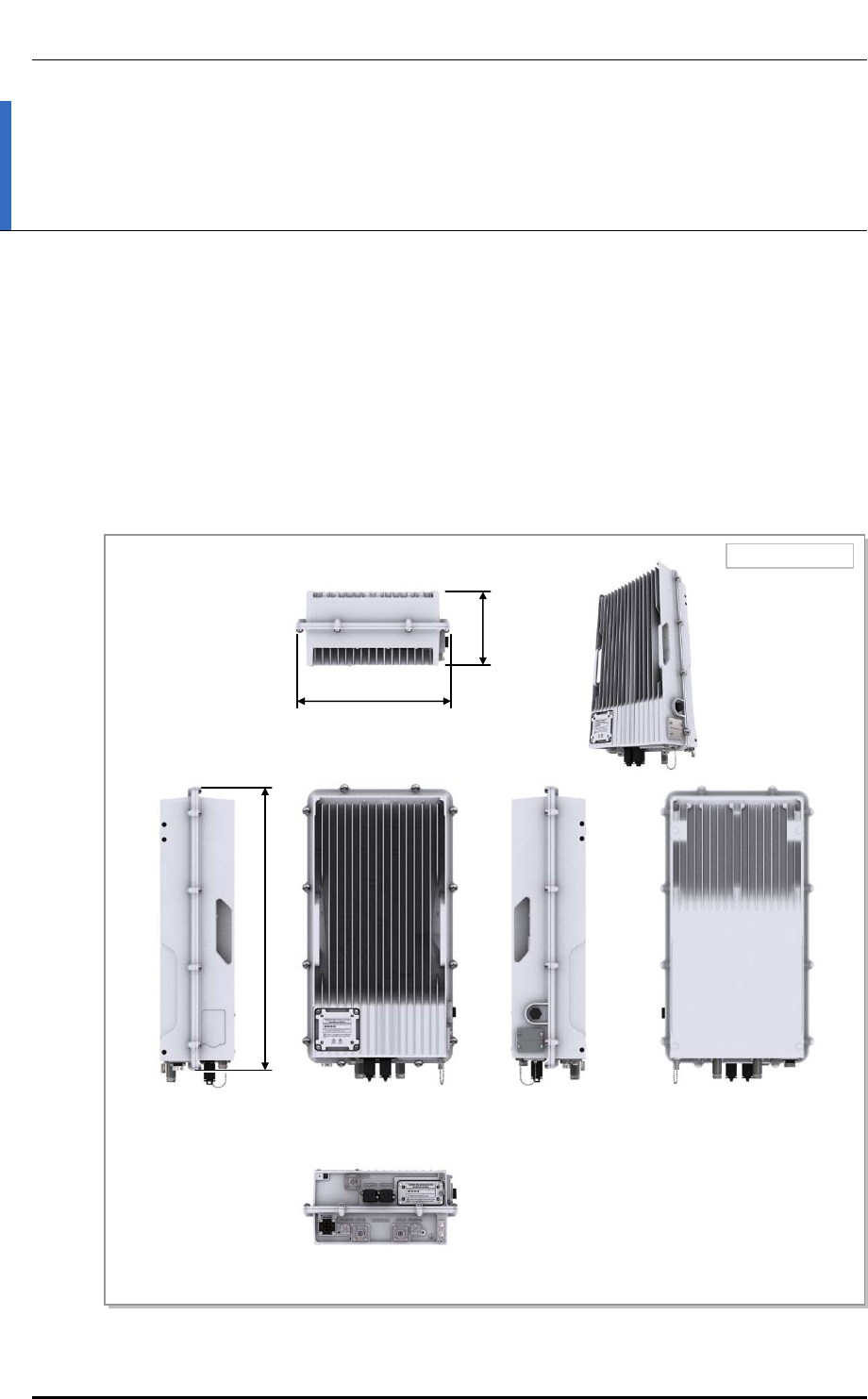
1.1 System Configuration
Outdoor Pico Configuration
The configuration of Outdoor Pico is as follows:
Figure 1. Outdoor Pico Configuration
U
ni
t
T
1
0.
1
P
P
S
60)
[Bottom View]
18.90 (480)
[Front View]
[Top View]
[Left View] [RiLM
T
View]
[RDE
BUG
ew]
4.94 (125.5)
Ver.
CHAPTER 1. Before Installation
© SAMSUNG Electronics Co., Ltd. page 19 of 116
1.0
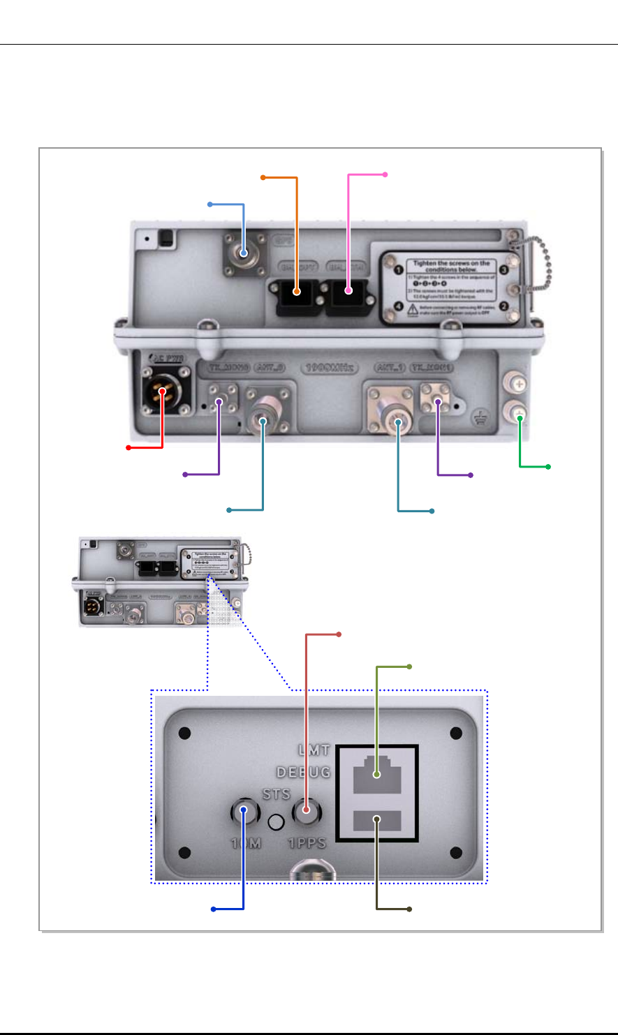
External Interface of Outdoor Pico
The external interface structure of Outdoor Pico is as follows:
Figure 2. External Interface of Outdoor Pico
GPS
BH_OPT BH_ETH
110~220 VAC
TX_MON 0
ANT_0
A
NT_1
TX_MON 1 FG
1PPS
LMT
DEBUG
10M [Bottom
Window]

Ver.
CHAPTER 1. Before Installation
© SAMSUNG Electronics Co., Ltd. page 20 of 116
1.0
1.2 Specifications
Key Specifications
The key specifications of the Outdoor Pico are as follows:
Table 1. Key Specifications
Category Specification
Air specification FDD LTE
Operating Frequency 1.9 GHz (Band 25)
Channel Bandwidth 5/10 MHz
Peak Throughput
(with Category 3 UE)
- 5 MHz BW: DL 32.1 Mbps (2x2 MIMO), UL 8.0 Mbps (1x2 SIMO)
- 10 MHz BW: DL 65.2 Mbps (2x2 MIMO), UL 18.3 Mbps (1x2 SIMO)
- Calculation condition: DL 0 % PHY error, UL 1 % PHY error
Tx Power 4 W/Path (Total 8 W)
Antenna Configuration 2Tx/2Rx
Backhaul Gigabit Ethernet 1 port (Copper)
Holdover 8 h
Power Specifications
The power specifications of the Outdoor Pico are as follows:
Table 2. Power Specifications
Category Standard
Rated voltage 120-240 V
With tolerance +/- 10%
Rated current 2A
Dimensions and Weight
The dimensions and weight of the Outdoor Pico are as follows:
Table 3. Dimensions and Weight
Item Specification
Size [in.(mm)], W × D × H 10.24 × 4.96 × 18.90 (260 × 126 × 480) or less
Weight 22 lb (10 kg) @ 1.9 GHz

Ver.
CHAPTER 1. Before Installation
© SAMSUNG Electronics Co., Ltd. page 21 of 116
1.0
GPSR Specifications
The specifications of the Outdoor Pico’s GPS receiver (GPSR) are as follows:
Table 4. GPSR Specifications
Item Specification
Received Signal from GPS GPS L1 Signal
Accuracy/Stability 0.05 PPM
Environmental Condition
The table below lists the environmental conditions and related standards such as
operational temperature and humidity
Table 5. Ambient Specifications
Category Range
Temperature Condition - (-30)~50°C (without solar load)
- (-30)~45°C (with solar load)
Humidity Condition 0 ~99 % (Relative humidity), not to exceed 30g/m^3 absolute
humidity
Altitude - Without sunlight
196~5,905 ft@122°F (-60)~1,800 m@50°C
5,905~13,123 ft@104°F (1,800~4,000 m@40°C)
- With sunlight
196~5,905 ft@113°F (-60)~1800 m@45°C
5,905~13,123 ft@95°F (1,800~4,000 m@35°C)
Earthquake Telcordia GR-63-Core (Zone4)
Sound Pressure Level Noise level is 45 dBA or lower at the location where is 3.28 ft (1 m)
away from the system (Sound level meter: based on IEC 61672)
Dust and waterproof rating IEC 60529 IP55
EMC FCC Title 47 Part 15 & 24
Ver.
CHAPTER 1. Before Installation
© SAMSUNG Electronics Co., Ltd. page 22 of 116
1.0
1.3 Cautions for Installation
Observe the following safety instructions when installing the Outdoor Pico:
Before Installing
y Post warning signs in areas where high-voltage cables are installed.
y Post ‘off limit’ signs in areas where accidents are most expected.
y With guardrails or fences, block open areas such as connecting parts, roof, and scaffold.
While Installing
y The system power must be cut off before installing.
y Be careful that boards mounted on the system and the cables among the boards are
damaged or scratched when the system is transported or installed.
Power Switch Off
Make sure the power switch of power supply is off when installing the system.
Installing the system with power switch on may cause system damage or fatal
human injury when cables are not correctly connected.
Protection gloves and goggles
Make sure that worker wears protection gloves and goggles to prevent damage
from debris while drilling holes in a wall or ceiling.
Do Not Wear Metal Things such as Watch, Ring, Etc.
Do not let the electric short circuit occur due to metal things such as watch or ring.
Management of Unused Ports
Cover the unused ports (conduit, cable gland, etc.) with waterproof cap (sealing
cap) to prevent infiltration of foreign material such as dust, moisture, or bug.
Do not use base station antenna within the distance of 100 cm from people and
also do not co-locate nor operate in conjunction with any other antenna or
transmitter for the protection of general public from exposure to radio frequency
electromagnetic field.
Ver.
CHAPTER 1. Before Installation
© SAMSUNG Electronics Co., Ltd. page 23 of 116
1.0
Finishing the System Input/output Port and Cable Inlet
To prevent foreign substances, outdoor air and moisture from entering the system
input/output port and cable inlet (including cable gland and conduit), finish it as
follows:
- Unused inlet
Use the hole finishing materials including waterproof cap and rubber packing.
- Cable-installed Port and Cable Inlet
After cable installation, block any space in the inlet with tape, compressed
sponge, rubber packing, and silicon.
Do not Work by Yourself
Worker must not work alone in any key process.
Outdoor Fastening Materials
The outdoor fastening materials such as stud bolts, hex. nuts, spring washers and
Plain washers must be made of stainless steel (STS 304).
Otherwise, it may cause corrosion and rust to fixing materials.
After Installing
y Cover the cable holes drilled on the floor with a solid cover.
y Remove any debris produced during the work and clean up the installation site.
Cautions while Cleaning the System
Make sure that worker does not damage installed cables while cleaning the
system.
Cautions while Cleaning Power Supply
While cleaning the power supply device, take caution that the device does not
come in contact with foreign objects that may cause power failure.
Ver.
CHAPTER 1. Before Installation
© SAMSUNG Electronics Co., Ltd. page 24 of 116
1.0
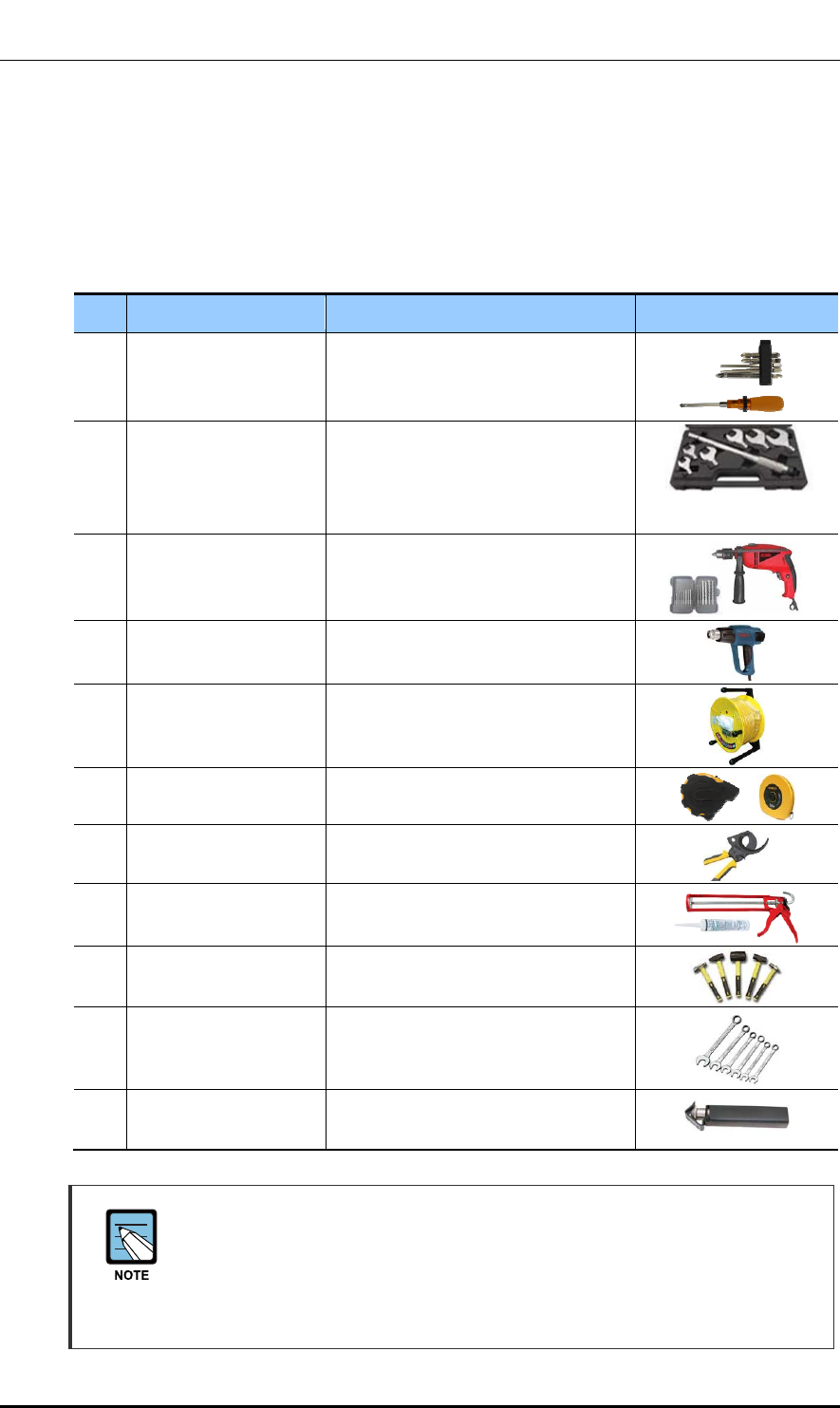
1.4 Installation Tools
The basic tools for installation are listed in the table below. The additional tools required
for each site need to identified and prepared during a site survey before starting installation.
Table 6. Basic Installation Tools
No. Name Specification Remarks
1 Torque Driver Set No.0~+No.3 (M2.6~M6 ‘+’ Driver)
0.07~4.34 lbf·ft (1.0~60 kgf·cm)
2 Torque Wrench Set M6~M12
0.72~2.17 lbf·ft (10~30 kgf·cm),
7.23~36.15 lbf·ft (100~500 kgf·cm),
Replaceable head
3 Drill/Bit Set 0.24~0.67 in. (6~17 mm)
4 Heating Gun 122~572 °F (50~300 °C)
5 Power Extension Cable 98.42 ft (30 m)
6 Tape Measure 16.4 ft/164 ft (5 m/50 m)
7 Cable Cutter 325 mm
8 Silicon Gun/Silicon Normal/Gray & Colorless
9 Hummer Set Still/Rubber/PVC
10 Spanner 0.75 in., 0.94 in., 1.42 in.
(19 mm, 24 mm, 36 mm)
11 Wire Stripper 0.24~0.94 in.
(6 mm~24 mm)
Precautions when Using the Installation Tools:
The required installation tools may vary depending on the conditions at the site.
In addition to the basic tools, a protractor, compass, GPS receiver, ladder, safety
equipment, cleaning tools etc. should also be prepared in consideration of the site
conditions.
Ver.
CHAPTER 2. Installing System
© SAMSUNG Electronics Co., Ltd. page 25 of 116
1.0
CHAPTER 2. Installing System
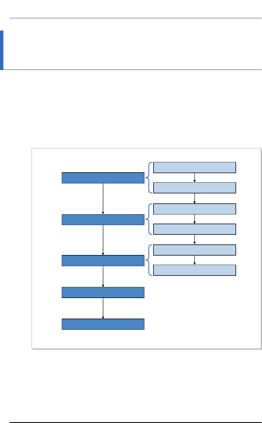
2.1 Installing the Outdoor Pico
The procedure to install the Outdoor Pico is listed in the flow chart below.
Figure 3. Procedure to Install the System
Foundation Work
Unpacking and Transporting
Marking and Drilling
System Arrangement
Fixing System
System Leveling
Installation Test
Unpacking Items
Importing Items
Pole Type Fixing
Wall Type Fixing
Ver.
CHAPTER 2. Installing System
© SAMSUNG Electronics Co., Ltd. page 26 of 116
1.0
2.2 Foundation Work
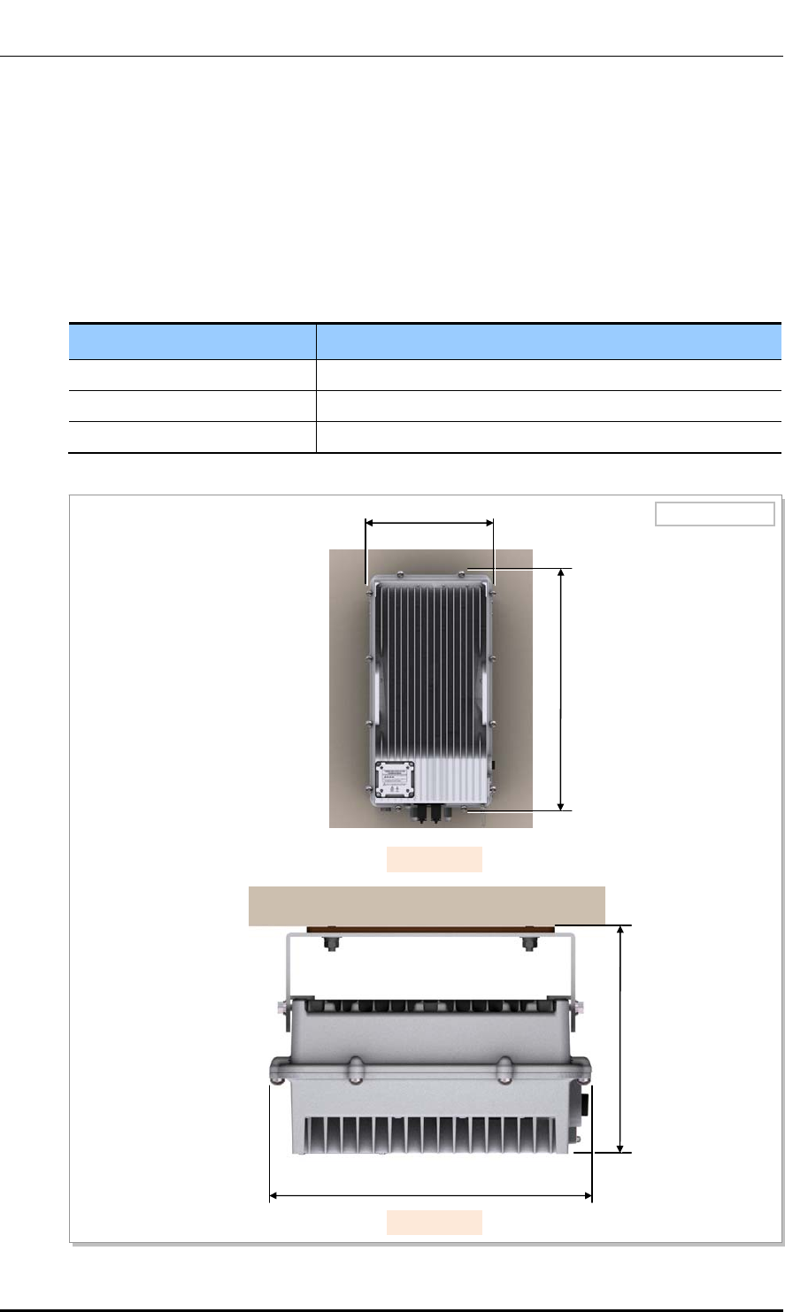
2.2.1 System Arrangement
A minimum distance must be secured around the Outdoor Pico, in each direction for
installation and maintenance.
Table 7. Recommended Distances for System
Category Recommended Distances
Front/Rear 31.5 in. (800 mm) or more
Side 7.87 in. (200 mm) or more
Top/Bottom 39.37 in. (1,000 mm) or more
Figure 4. Outdoor Pico Arrangement(Wall Type)
Unit: in. (mm)
18.90 (480)
[Front View]
[Top View]
10.23 (260)
≒ 7.22 (183.5)
10.24 (260)
Ver.
CHAPTER 2. Installing System
© SAMSUNG Electronics Co., Ltd. page 27 of 116
1.0
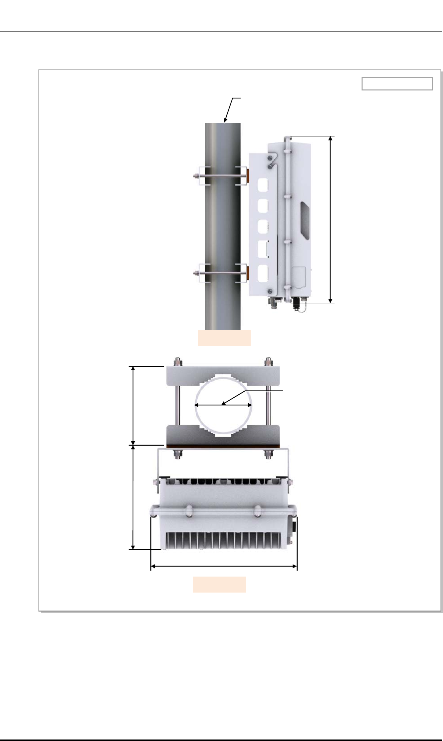
Figure 5. Outdoor Pico Arrangement(Pole Type)
[Top View]
Pole: (Ф 3~4.5 in. / Ф 76.3~114.3 mm)
[Side View]
Unit: in. ( mm)
18.90 (480)
10.23 (260)
≒ 7.22 (183.5) ≒ 5.57 (141.6)
Pole: (Ф 3~4.5 in. / Ф 76.3~114.3
Ver.
CHAPTER 2. Installing System
© SAMSUNG Electronics Co., Ltd. page 28 of 116
1.0
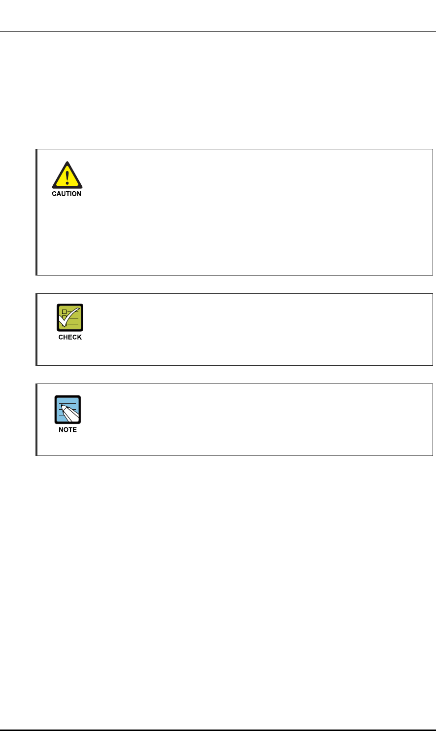
2.2.2 Marking and Drilling
Marking
Before placing the system, mark the position where the system will be installed and also
the positions where anchor bolts will be fixed using a ink line or a pen.
Checking Marking (horizontal/vertical) When Mounting the System on Wall
If you do the drilling or anchoring on a wall when the positions are not marked to
be horizontal or vertical, only limited range of tuning is allowed for leveling after
the system is mounted.
To mount the system on a wall, perform the leveling test by referring to ‘System
Leveling’ to check the positions are marked to be horizontal or vertical before
drilling. If the result shows they are not horizontal or vertical, modify the marking
positions.
Position, Specifications and Marking of Anchor Bolt
Before starting work, be sure to check the fixing method for the Outdoor Pico
because the marking and drilling positions and specifications may differ per the
fixing method.
Marking Using the System
When the position where the system will be placed is determined, place the
system on the position and then mark the positions where anchor bolts will be
fixed using a pen. This will reduce marking error range caused by a worker.
Ver.
CHAPTER 2. Installing System
© SAMSUNG Electronics Co., Ltd. page 29 of 116
1.0
Figure 6. System Marking-Wall Type
Drilling
When marking is completed, drill holes for anchor bolts.
Table 8. Anchor Bolt Drill Bits and Hole Depth
Category Anchor Bolt Drill Bits Hole Depth
Wall Type M4 0.24 in. (6 mm) 1.18 in. (30 mm)
Anchor Bolt Hole Ф 0.47(12)
6.30(160)
11.02(280)
16.22(412)
9.17(232.8)
2.60(66)
1.43(36.4)
2.60(66)
Unit: in.(mm)
1.43(36.4)

Ver.
CHAPTER 2. Installing System
© SAMSUNG Electronics Co., Ltd. page 30 of 116
1.0
2.3 Unpacking and Transporting
This paragraph describes the work to unpack cabinets and other components and transport
them to the place to be installed.
2.3.1 Bringing in Items
Bring in items, taking care of the followings:
y Carry boards in packing boxes, and unpack them when installing or mounting.
y Tighten the system firmly not to exceed the proper vibration level from 1 to 500 Hz.
y Use a lift or cart to prevent accidents. However, if the system must be carried by
people, make sure that there are enough people to carry the system safely.
y Before moving the system, check the storage place and remove obstacles in advance.
y While moving system, boards and other devices should not be damaged caused by
physical shock, dust, moisture, and static electricity.
2.3.2 Unpacking Items
The procedure to unpack items is as follows:
y The items should be packed until they reach the installation place.
y The items are classified in accordance with each job specification and stored on a
place that does not interfere with the working area.
y Unpacked systems should be installed immediately. If not installed immediately, the
systems should be stored in the installation place temporarily.
y Unpack the inner packaging after each system is placed on its installation location.
y Do not recycle packaging waste. Dispose of it in accordance with waste management
rule.
Ver.
CHAPTER 2. Installing System
© SAMSUNG Electronics Co., Ltd. page 31 of 116
1.0
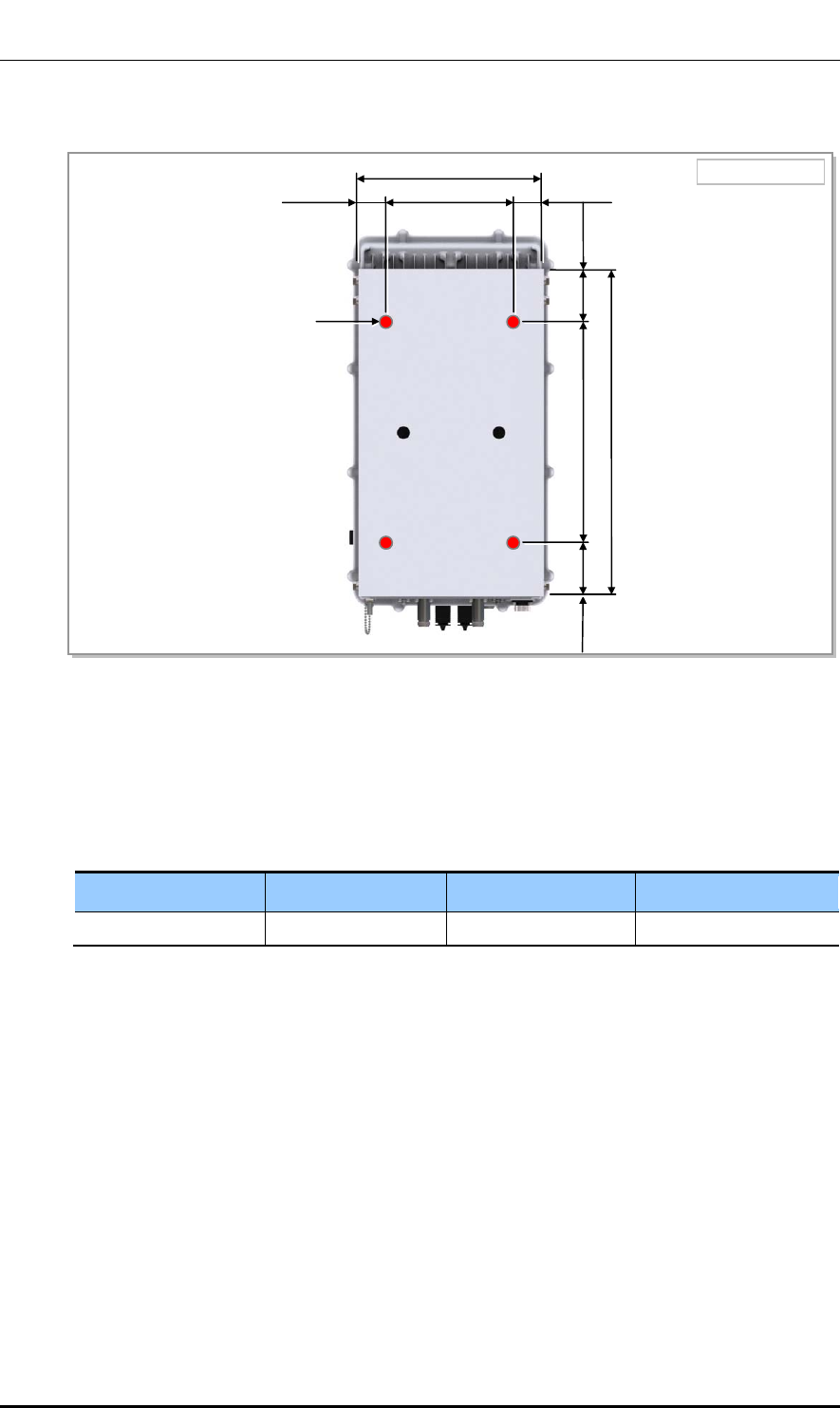
2.4 Fixing System
The installation tools and assembly torque required to install and maintain the Outdoor
Pico are as follows:
Table 9. Outdoor Pico Installation Tools and Torque Value
Category Installation Tools Torque Value
A Maintenance Window Screw Star Pole Type Screw Driver :
M4
0.87 lbf·ft(12 kgf·cm)
B M6 SEMS Driver(+) : M6 1.45~2.17 lbf·ft
(20~30 kgf·cm)
C SMA Hexagon: 0.39 in.(10 mm) 0.36 lbf·ft(5.0 kgf·cm)
D N-Type Hexagon: 0.75 in.(19 mm) 0.87 lbf·ft(12.0 kgf·cm)
[Front View]
‘D’
‘B’
‘D’
‘D’ ‘C’‘C’
‘A’
[Bottom View]
‘A’

Ver.
CHAPTER 2. Installing System
© SAMSUNG Electronics Co., Ltd. page 32 of 116
1.0
Table 10. Tightening Parts for Outdoor Pico
Category Installation Tools Torque Value
M8 Hex. Bolt Hexagon: 0.51 in. (13 mm) 8.82 lbf·ft (122.0 kgf·cm)
Hex. Nut
Outdoor Fastening Materials
The outdoor fastening materials such as stud bolts, hex. nuts, spring washers and
Plain washers must be made of stainless steel (STS 304).
Ver.
CHAPTER 2. Installing System
© SAMSUNG Electronics Co., Ltd. page 33 of 116
1.0
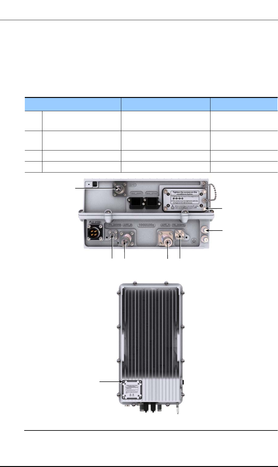
2.4.1 Assembling Tightening Parts for Outdoor Pico
The figure below shows how to assemble the tightening parts to the fixing holes at the top
of left/right sides to install the Outdoor Pico to the mounting bracket.
Table 11. Tightening Parts and Tools for Installing Outdoor Pico
Category Description
Fastener M8 × 16L Hex. Bolt 2 EA
M8 Spring Washer 2 EA
M8 Plain Washer 2 EA
Working Tools Spanner(Hexagon : 13 mm), Steel Ruler
Figure 7. Assembling Tightening Parts for Installing Outdoor Pico
Tighten the fasteners to the second fixing holes on the left and right sides of the top of the Outdoor Pico,
leaving about 0.24 in. (6 mm) clearance.
M8 × 16L Hex. Bolt
≒ 0.24 in. (6 mm)
M8 Spring Washe
r
M8 Plain Washe
r
≒ 0.24 in. (6 mm)
Ver.
CHAPTER 2. Installing System
© SAMSUNG Electronics Co., Ltd. page 34 of 116
1.0
2.4.2 Fixing the Outdoor Pico(Wall Type)
The procedure for fixing the Outdoor Pico on the wall is as follows:
Fixing Unit Mounting Bracket
The procedure for fixing the unit mounting bracket is as follows:
Table 12. Unit Mounting Bracket Fixing Parts and Tool (Wall Type)
Category Description
Parts Unit Mounting Bracket 1 EA
Bakelite (5T) 2 EA
Fastener M8 Anchor Bolt Assembly
- M8 Anchor Bolt
- M8 Plain Washer
- M8 Spring Washer
- M8 Hex. Nut
4 set
1 EA/set
1 EA/set
1 EA/set
1 EA/set
M8 Insulation Bushing 4 EA
Recommended Torque Value M8 Hex. Nut 8.82 lbf·ft(122 kgf·cm)
Working Tools Drill, Hammer, Torque Wrench, and Level
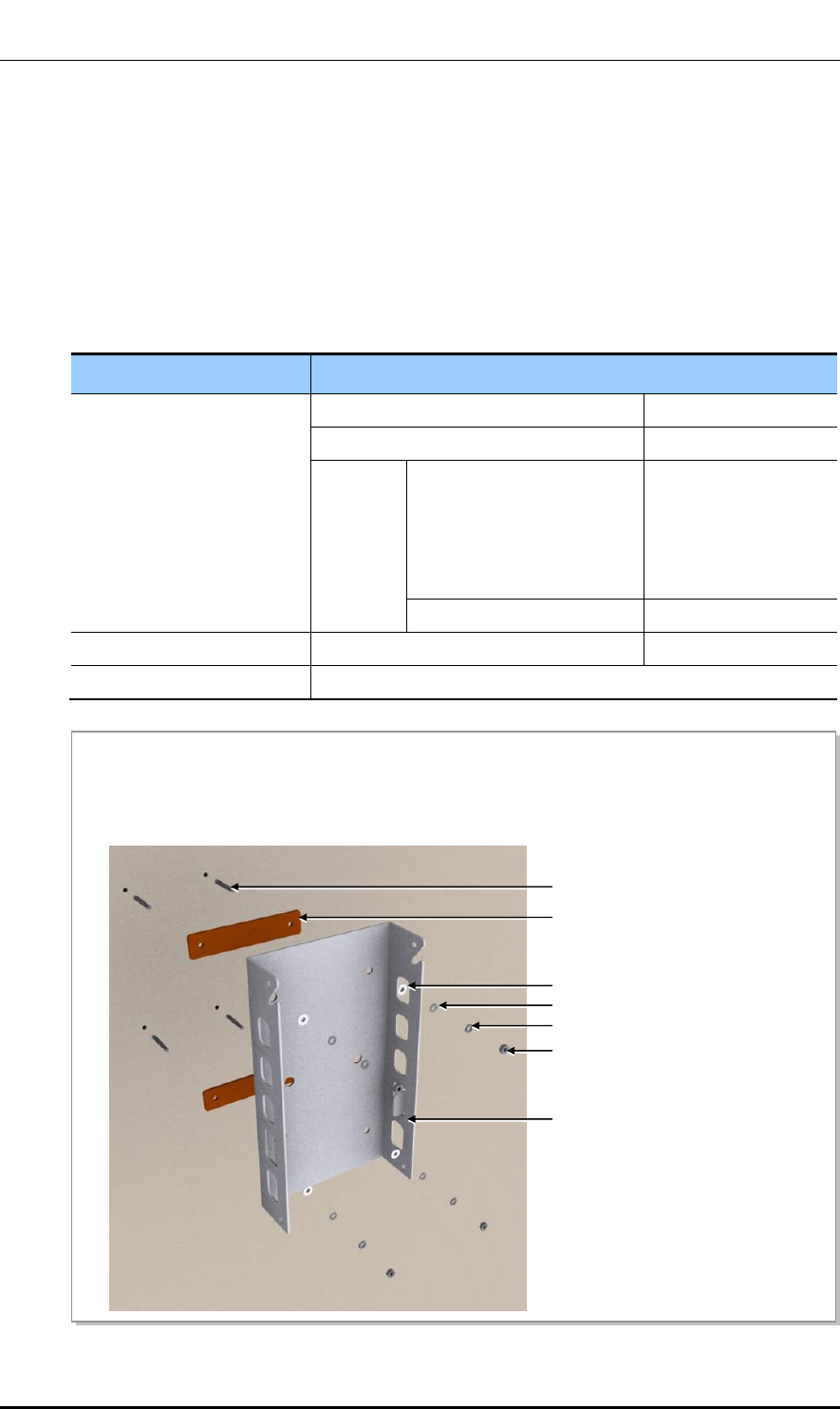
Figure 8. Fixing Unit Mounting Bracket (Wall Type)
1) Fix anchor bolts at the marked locations on the wall.
2) Fit the bakelite and unit mounting bracket to the fixed anchor bolts.
3) Firmly fix the anchor bolts and unit mounting bracket using the fasteners.
M8 Insulation Bushing
Bakelite
M8 Anchor Bolt
M8 Plain Washer
M8 Spring Washer
M8 Hex. Nut
Unit Mounting Bracket
Ver.
CHAPTER 2. Installing System
© SAMSUNG Electronics Co., Ltd. page 35 of 116
1.0
Fixing the Outdoor Pico
Mount Outdoor Pico to the unit mounting brackets as shown below.
Table 13. Outdoor Pico Fixing Parts and Tools (Wall Type)
Category Description
Parts M8 × 16L Hex. Bolt 4 EA
M8 Spring Washer 4 EA
M8 Plain Washer 4 EA
Recommended Torque Value M8 Hex. Bolt 8.82 lbf·ft(122 kgf·cm)
Working Tools Torque Wrench and Level
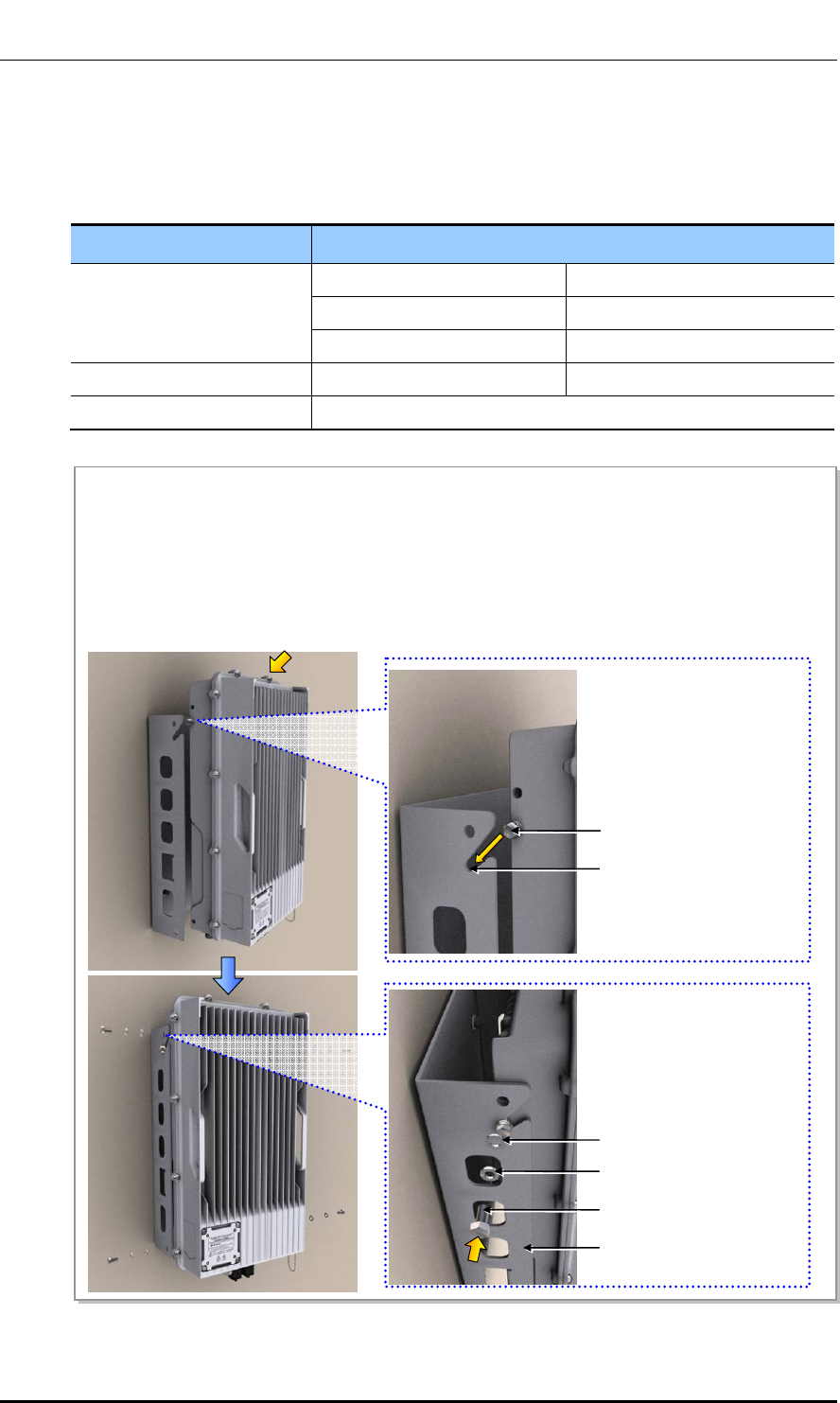
Figure 9. Fixing the Outdoor Pico (Wall Type)
1) Hang M8 hex. bolts, which are installed in the second fixing holes on left/right sides of Outdoor Pico,
can on the groove at the top of the unit mounting bracket. At this point, the plain washer and spring
washer should be located outside of the unit mounting bracket.
2) Fix the product securely by tightening fasteners on the remaining holes of the unit mounting bracket.
3) Tighten completely and securely the M8 hex. bolts attached to the second fixing holes on the top of the
Outdoor Pico.
Top groove of Unit Mounting
Mounting Bracket
M8 × 16L Hex. Bolt
Unit Mounting Bracket
M8 Plain Washer
M8 Spring Washer
M8 × 16L Hex. Bolt
Ver.
CHAPTER 2. Installing System
© SAMSUNG Electronics Co., Ltd. page 36 of 116
1.0
2.4.3 Fixing the Outdoor Pico (Pole Type)
The procedure for fixing the Outdoor Pico on the 1 sector pole type is as follows:
Fixing Unit Mounting Bracket and Pole Mounting Bracket
The procedure for fixing the unit mounting bracket and pole mounting bracket is as
follows:
Table 14. Unit/Pole Mounting Bracket Fixing Parts And Tool
Category Description
Parts Pole Mounting Bracket 4 EA
Unit Mounting Bracket 1 EA
Bakelite (5T) 2 EA
Fastener M8 × 180L Stud Bolt
M8 Plain Washer
M8 Spring Washer
M8 Hex. Nut
4 EA
8 EA
8 EA
8 EA
M8 Insulation Bushing 4 EA
Recommended Torque Value M8 Hex. Nut 8.82 lbf·ft(122 kgf·cm)
Working Tools Torque Wrench, and Level
Ver.
CHAPTER 2. Installing System
© SAMSUNG Electronics Co., Ltd. page 37 of 116
1.0
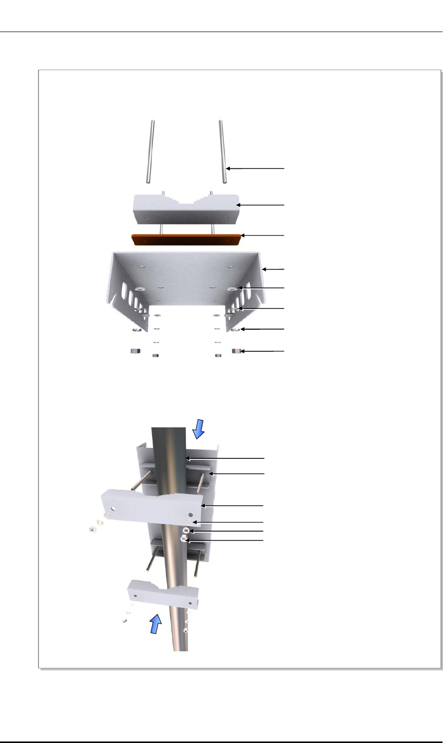
Figure 10. Fixing Unit Mounting Bracket and Pole Mounting Bracket
1) Align the holes on the unit mounting bracket, bakilite and pole mounting bracket, and assemble the unit
mounting bracket using the fasteners.
M8 Insulation Bushing
Pole Mounting Bracket
Bakelite
M8 Plain Washer
M8 Spring Washer
M8 × 180L stud Bolt
Unit Mounting Bracket
2) Place the assembled Outdoor Pico mounting bracket assembly over the pole fixing location, adjust the
pole mounting bracket to fit the M8 × 180L hex.bolts from the opposite side, and fix it securely using
the fasteners.
Pole
M8 Spring Washer
M8 Plain Washer
Pole Mounting Bracket
M8 Hex. Nut
M8 Hex. Nut
Outdoor Pico Mounting Bracket Assembly
Ver.
CHAPTER 2. Installing System
© SAMSUNG Electronics Co., Ltd. page 38 of 116
1.0
Fixing the Outdoor Pico
Mount Outdoor Pico to the unit mounting brackets as shown below.
Table 15. Outdoor Pico Fixing Parts and Tools (Pole Type)
Category Description
Parts M8 × 16L Hex. Bolt 4 EA
M8 Spring Washer 4 EA
M8 Plain Washer 4 EA
Recommended Torque Value M8 Hex. Bolt 8.82 lbf·ft(122 kgf·cm)
Working Tools Torque Wrench and Level
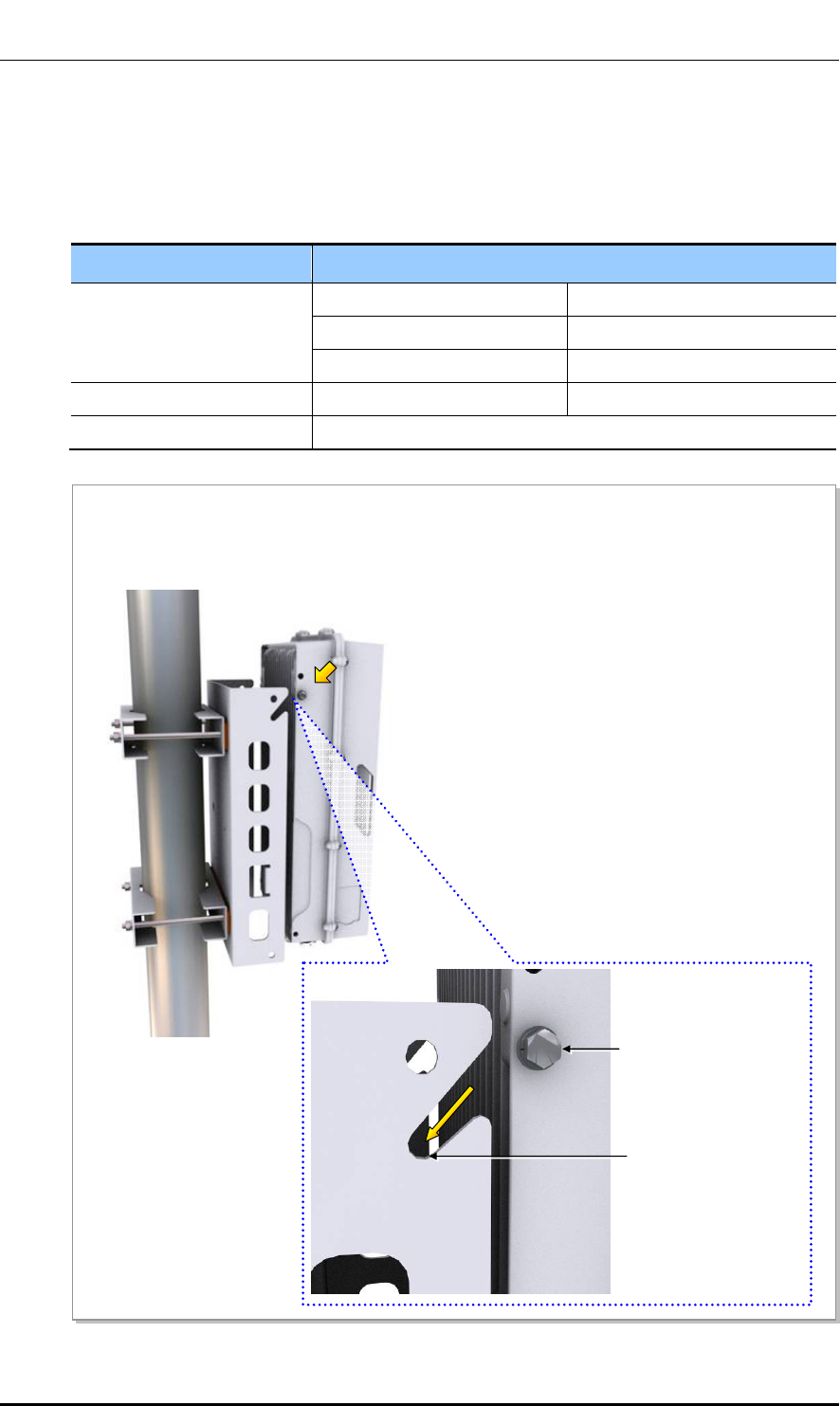
Figure 11. Fixing the Outdoor Pico_Pole Type (1)
1) Hang M8 hex. bolts, which are installed in the second fixing holes on left/right sides of Outdoor Pico,
can on the groove at the top of the unit mounting bracket. At this point, the plain washer and spring
washer should be located outside of the unit mounting bracket.
Top groove of
Unit Mounting Bracket
M8 × 16L Hex. Bolt
Ver.
CHAPTER 2. Installing System
© SAMSUNG Electronics Co., Ltd. page 39 of 116
1.0
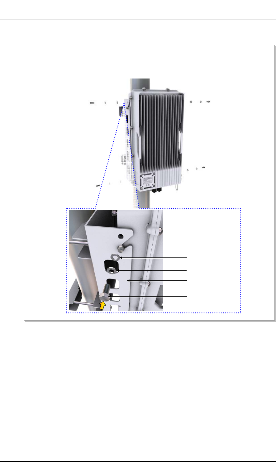
Figure 12. Fixing the Outdoor Pico_Pole Type (2)
2) Fix the product securely by tightening fasteners on the remaining holes of the unit mounting bracket.
3) Tighten completely and securely the M8 hex. bolts attached to the second fixing holes on the top of the
Outdoor Pico.
Unit Mounting Bracket
M8 Plain Washer
M8 Spring Washer
M8 × 16L Hex. Bolt
Ver.
CHAPTER 2. Installing System
© SAMSUNG Electronics Co., Ltd. page 40 of 116
1.0
2.5 System Leveling
Leveling refers to compensating for the level difference on the floor that is generated
during floor work to install devices horizontally or vertically. Leveling can be carried out
using a vinyl hose, a balance weight, or a level.
In this manual, a commonly used method, which uses a spirit level, is described.
Leveling Using a Level
Leveling method using a level is as follows:
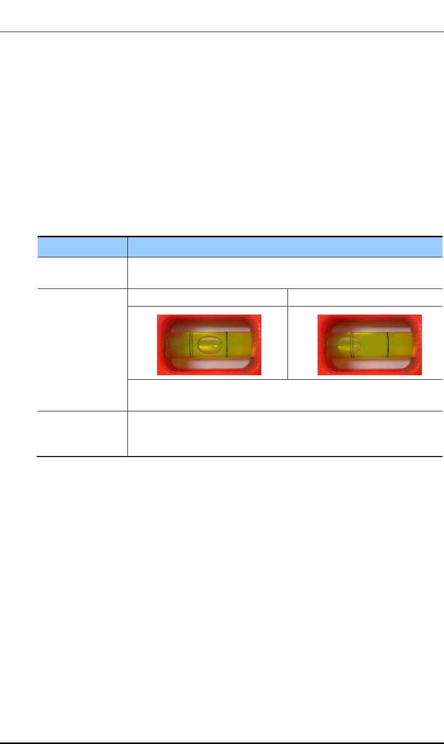
Table 16. Leveling Using a Level
Classification Description
Test method The level is measured based on the position of a bubble after attaching the
spirit level to the top and side of the system.
Evaluation criteria Good Poor
If it is leveled, the bubble of the spirit level is positioned at the center of both
lines.
Corrective
measures for poor
leveling
Use an aid such as bakelite on the back side of the system or an auxiliary
fixtures to adjust the height.
Adjust the position of fasteners used to fix the system or its leveling status.
Ver.
CHAPTER 2. Installing System
© SAMSUNG Electronics Co., Ltd. page 41 of 116
1.0
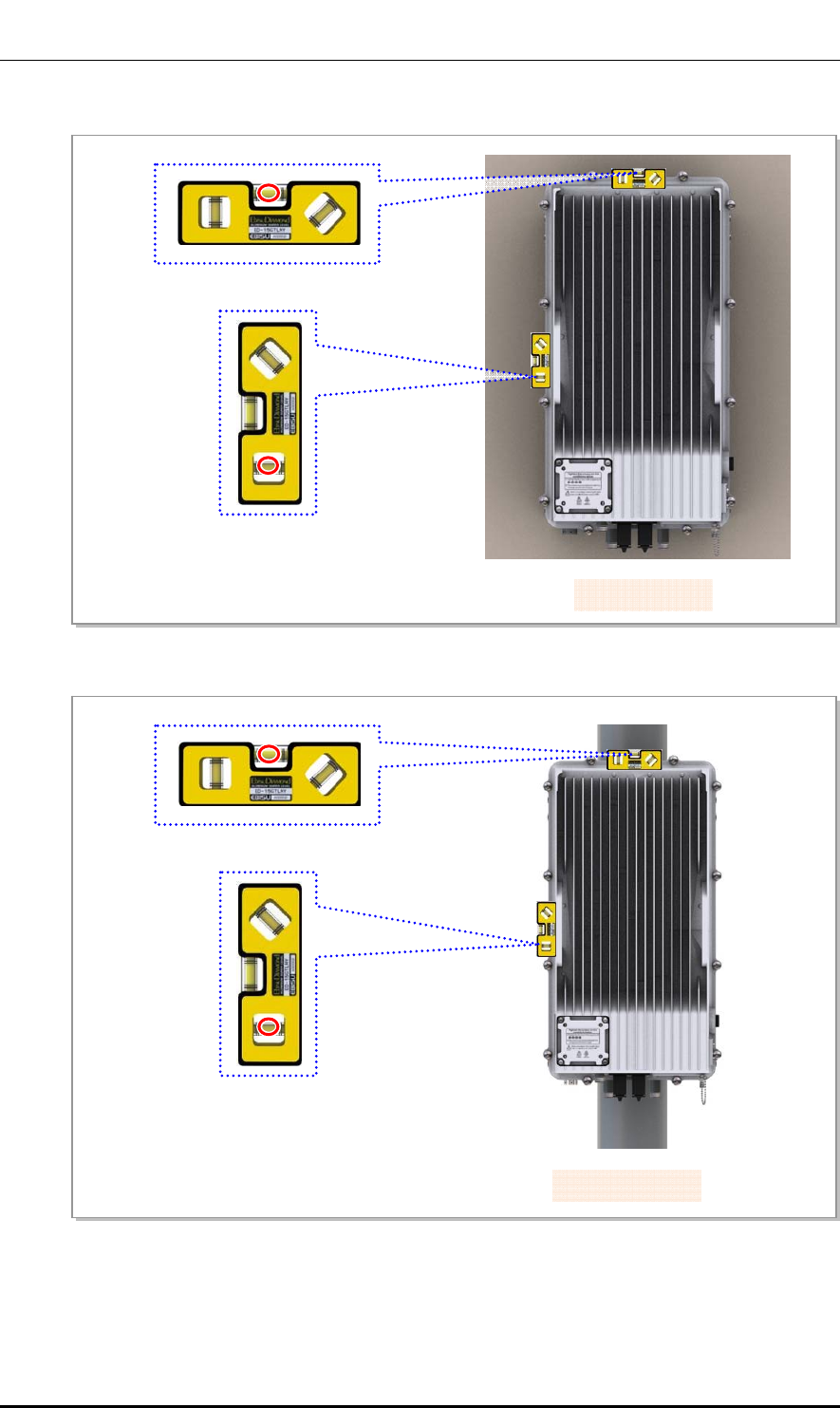
Figure 13. Leveling Using a Level (Wall Type)
Figure 14. Leveling Using a Level (Pole Type)
[Measuring Vertical Position]
[Measuring Horizontal Position]
[Pole Type]
[Wall Type]
[Measuring Vertical Position]
[Measuring Horizontal Position]
Ver.
CHAPTER 2. Installing System
© SAMSUNG Electronics Co., Ltd. page 42 of 116
1.0
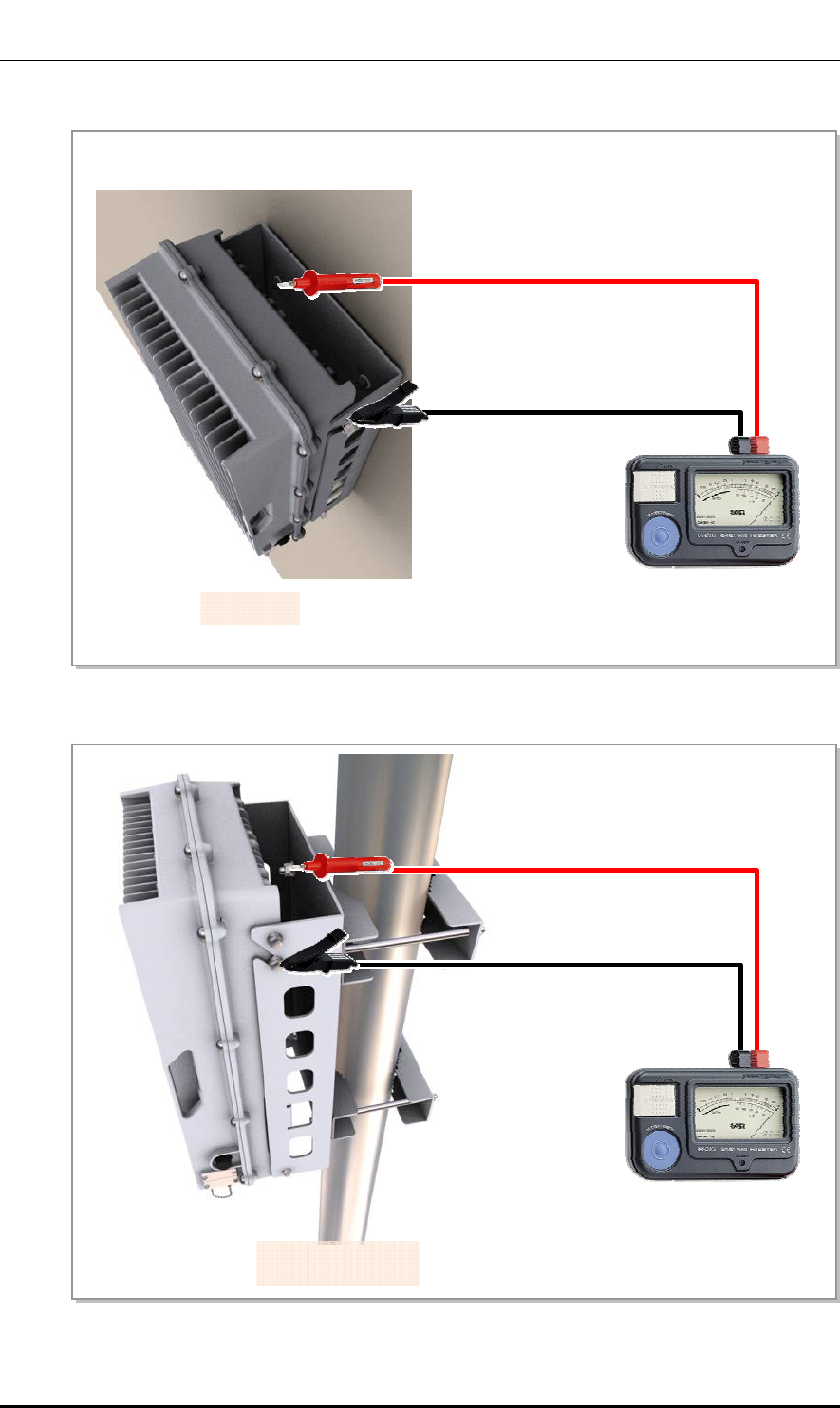
2.6 Insulation Test
Insulation test procedure is as follows:
Table 17. Insulation Test
Classification Description
Test method The insulation tester (Megger) is used for measurement.
Position of lead
line of insulation
tester
Wall Type Lead line_A Anchor Bolt
Lead line_B Outdoor Pico Fixing Hex. Bolt
Pole Type Lead line_A M8 × 180L Stud Bolt
Lead line_B Outdoor Pico Fixing Hex. Bolt
Evaluation
criteria
Good Poor
500 V/100 MΩ or more Less than 500 V/100 MΩ
Corrective
measures for
poor leveling
- Check the contact between the system and anchor bolt and re-assemble it.
(But, the anchor bolt must be shielded using an insulator such as an insulation
bushing, etc.)
- Check damage of an insulator such as an insulation busing or bakelite, etc.
and replace it.
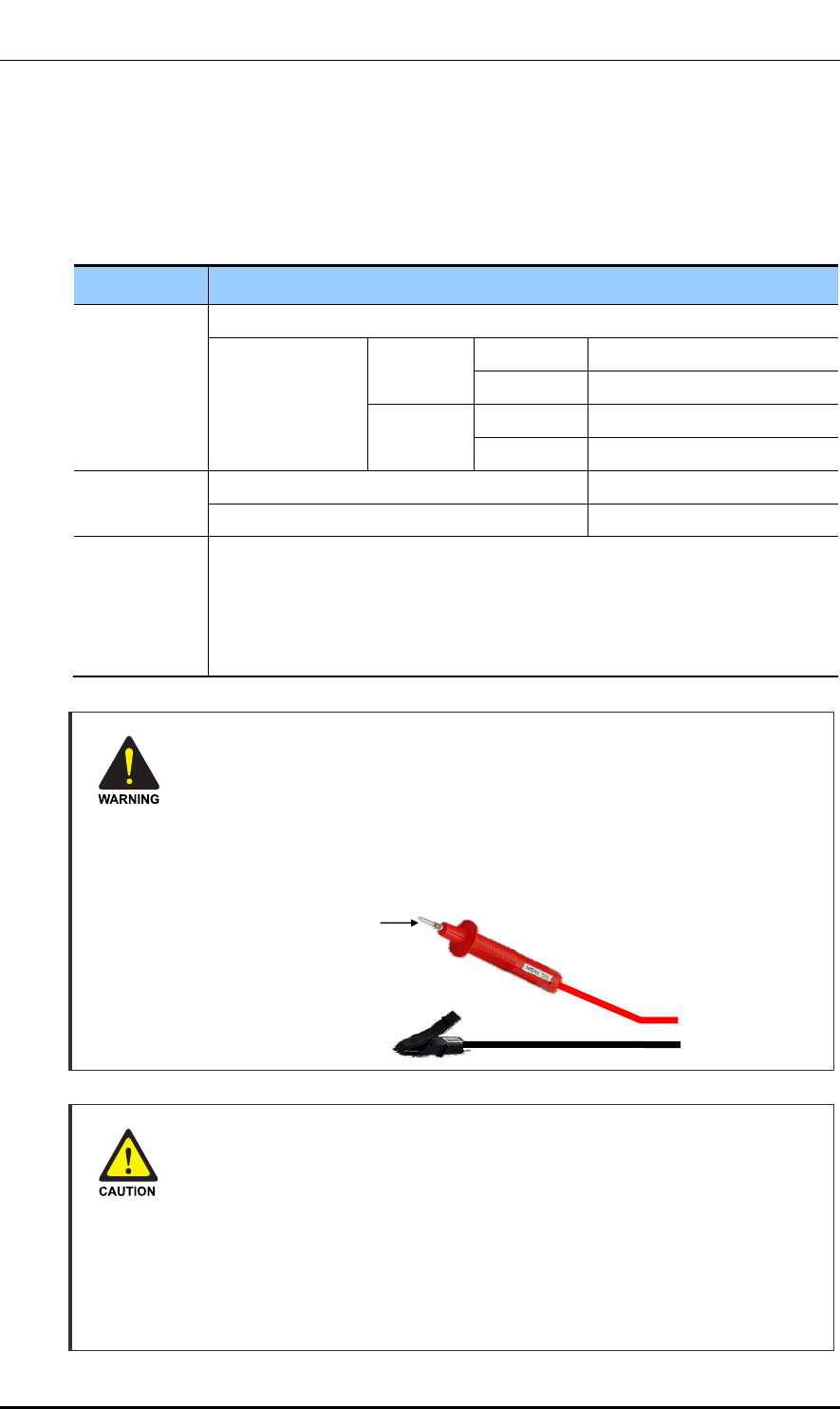
Cautions When Using Insulation Tester
Pay attention to the followings to prevent any personal injury caused by an
electric shock when using an insulation tester.
- Make sure the polarity is correct when connecting the Earth COM (black) and
AC.V (red) lead lines. And do not touch the connected probes inspecting part of
the lead line) with a hand and avoid body contact.
- Avoid body contact to the system when measuring an insulation resistance.
Precautions While Measuring Insulation Resistance
Observe the followings to prevent any system damage when measuring insulation
resistance because there is a very high voltage.
- Before measuring insulation resistance, disconnect all the cables connected to
the system.
- Do not measure insulation resistance when power is on.
- Do not measure insulation resistance at any other positions such as system
internal units or parts other than the targeted insulation resistance measuring
points.
Probe
(Inspecting part of the
lead line)
Ver.
CHAPTER 2. Installing System
© SAMSUNG Electronics Co., Ltd. page 43 of 116
1.0
Figure 15. Schematic Diagram for Insulation Test (Wall Type)
Figure 16. Schematic Diagram for Insulation Test (Pole Type)
Anchor Bolt
[Megger]
[Wall Type]
Outdoor Pico Fixing Hex. Bolt
M8 × 180LStud Bolt
[Megger]
[Pole Type]
Outdoor Pico Fixing Hex. Bolt
Ver.
CHAPTER 3. Connecting Cables
© SAMSUNG Electronics Co., Ltd. page 44 of 116
1.0
CHAPTER 3. Connecting Cables
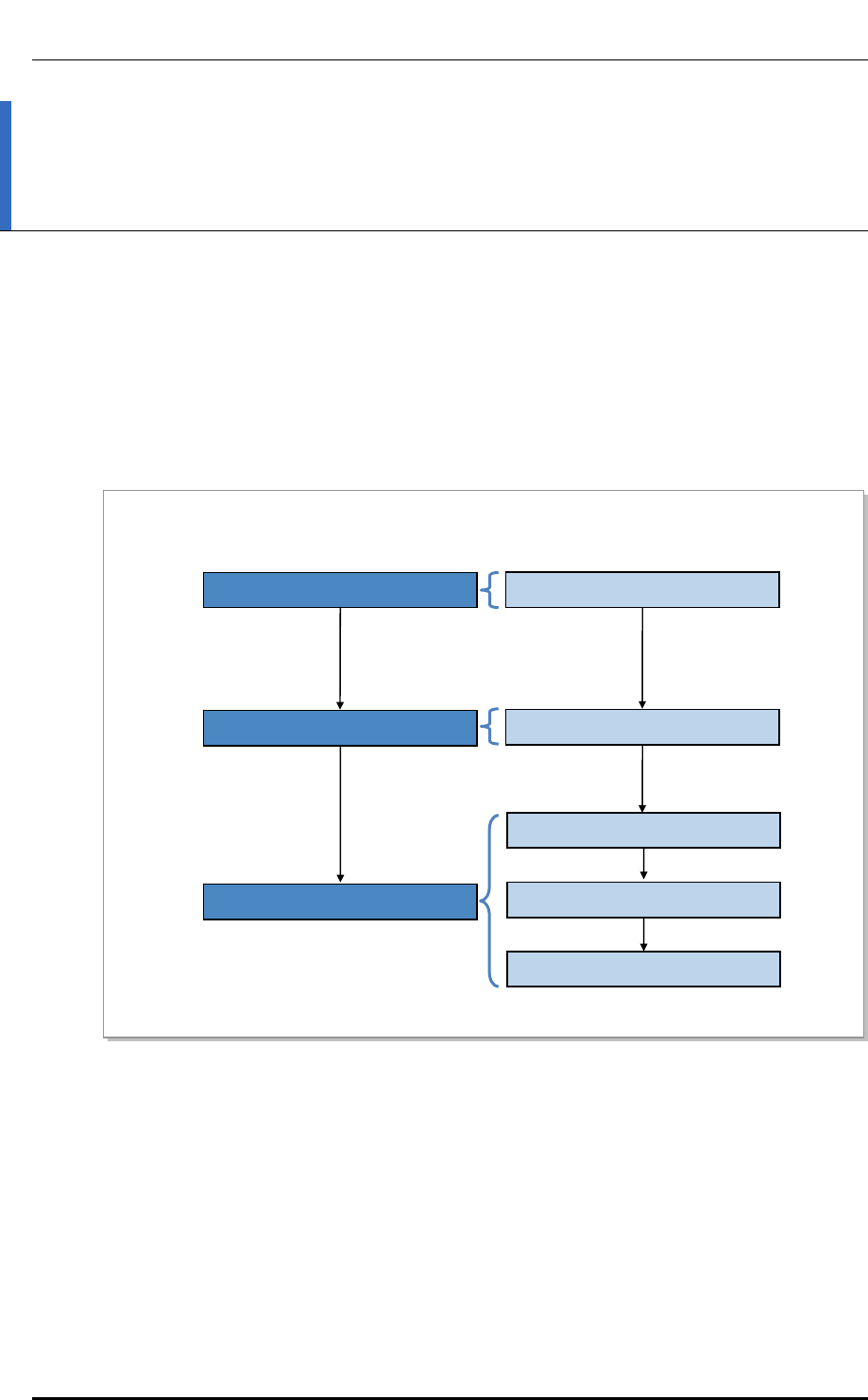
3.1 Work Flow for Cabling
The cable workflow for the system is as follows:
Figure 17. Work Flow for System Cabling
Grounding
Power Cabling
System Ground Cable Connection
External Interface Construction
Backhaul Cable Connection
GPS Cable Connection
RF Cable Connection
System Power Cable Connection
Ver.
CHAPTER 3. Connecting Cables
© SAMSUNG Electronics Co., Ltd. page 45 of 116
1.0
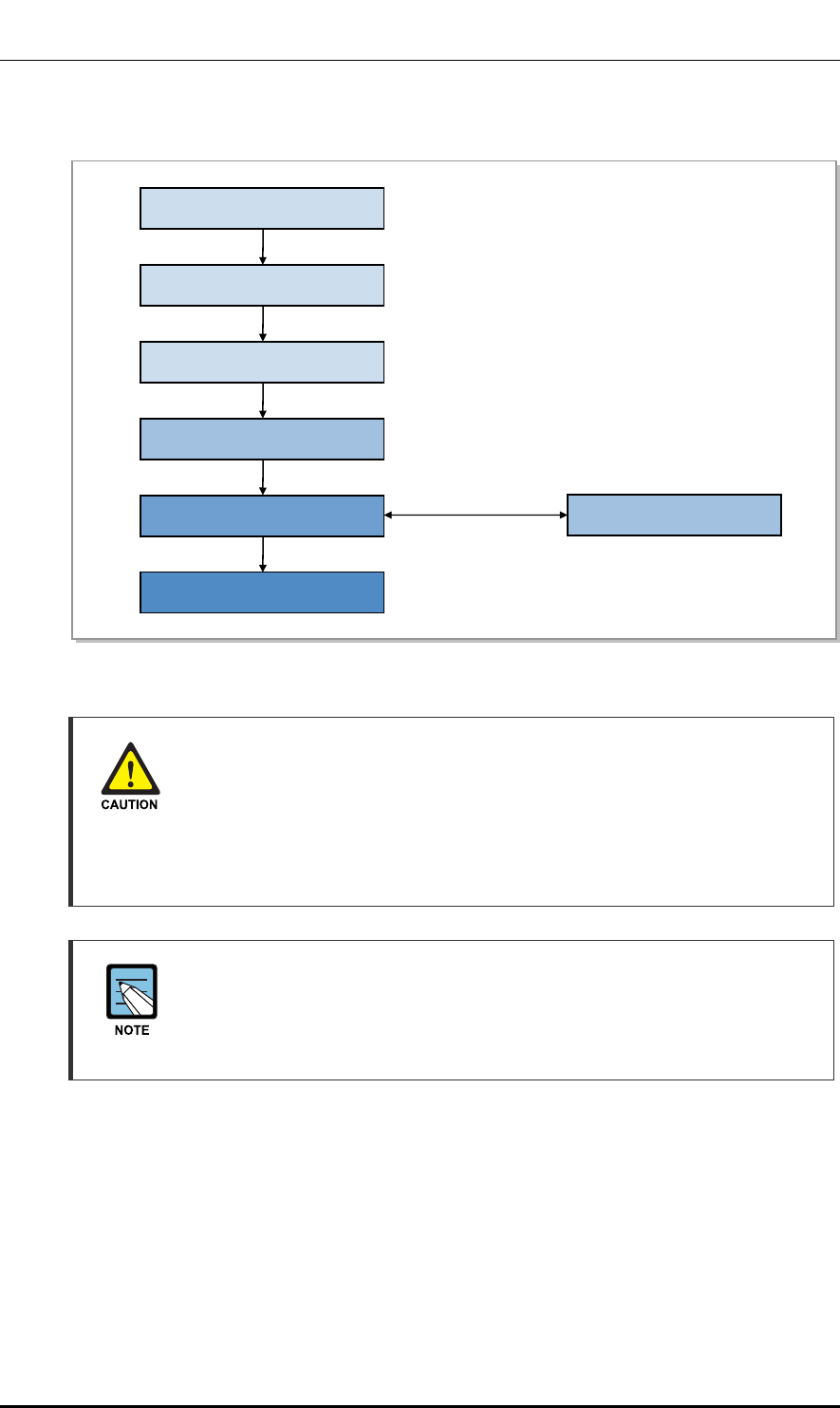
The detailed procedure of cabling is as follows:
Figure 18. Detailed Cabling Procedure
Considerations when Cutting the Cable after Installation
When cutting the cable after installation, first make sure that the connector is
disconnected from the equipment. Installation of the cable with the connector
connected to the system may cause contact failure or damage to the connector
assembled to the system and the cable due to cable tension or the operator’s
mistakes.
Cabling Workflow
The sequence of cable cutting and installation of the cable workflow can be
changed depending on the field situation such as ‘cutting after installing’ or
‘installing after cutting’.
Cable Installation
Cable Binding
Connector Attachment
Identification Tag Attachment
Connector Assembly
When assembling the
connector at the site
Cable Path Inspection
Cable Cutting

Ver.
CHAPTER 3. Connecting Cables
© SAMSUNG Electronics Co., Ltd. page 46 of 116
1.0
Cable Path Inspection
When installing a cable that connects between the rectifier, Main Ground Bar (MGB), and
backhaul device, etc. within the system, the cable path, length and the cable installation
method, etc. must be inspected.
Follow these guidelines when inspecting the cabling path.
y A minimum cable length must be selected provided that it does not affect the cable
installation and maintenance.
y The cable must be placed in a location where it will not be damaged by external
factors. (power line, flooding, footpaths, etc.)
y In areas where the cable may be damaged by external factors, ensure that measures are
taken to prevent damage to the cable. (cable tray, ducts, flexible pipe, etc.)
Cable Cutting
Measure the exact distance, carefully checking the route, and cut the cable using a cutting tool.
Follow these guidelines when cutting the cable.
y Cut the cable to the length determined in the Cable Path Inspection step.
y Use a cable cutting tool specific to the cable.
y Cut the cable at right angles.
y Be careful to keep the cable away from any moisture, iron, lead, dust or other foreign
material when cutting.
y Remove any foreign material attached to the cable using solvent and a brush.
Cable Installation
Cable installation involves running the cable along the cabling path to the target connector
of the system or an auxiliary device after cable path inspection and cable cutting have been
completed.
Follow these guidelines when installing a cable.
y Be careful not to damage the cable.
y If the cable is damaged, cut out the damaged section before installing, or replace the
cable.
y Run the cable so that it is not tangled. In particular, when installing a cable from a
horizontal section to a vertical section, be careful not to reverse the upper and lower
lines of the cable.
y Always use the maximum curvature radius possible, and make sure that the minimum
curvature radius specification is complied with.
y If the cable needs to be protected, use a PVC channel, spiral sleeve, flexible pipe, and
cable tray, etc.

Ver.
CHAPTER 3. Connecting Cables
© SAMSUNG Electronics Co., Ltd. page 47 of 116
1.0
Table 18. Recommended Minimum Allowed Cable Bend Radius
No Type Allowed Cable Bend Radius Remark
1 F-GV/F-CV/FR-8 8 times of the cable external diameter 0.6/1 KV Cable
2 Optic Cable 20 times of the cable external diameter -
3 UTP/FTP/S-FTP Cable 4 times of the cable external diameter PVC/LSZH,
4 Pair
4 1/2 in. Feeder Line (Indoor) 1.26 in. (32 mm) RFS, LS
5 1/2 in. Feeder Line (Outdoor) 4.92 in. (125 mm) RFS, LS
6 7/8 in. Feeder Line (Outdoor) 9.84 in. (250 mm) RFS, LS
7 1-1/4 in. Feeder Line (Outdoor) 14.96 in. (380 mm) RFS, LS
8 1-5/8 in. Feeder Line (Outdoor) 19.69 in. (500 mm) RFS, LS
9 RG-316D 0.59 in. (15 mm) -
※ If the allowed cable bend radius is specified by the manufacturer, comply with the bend radius specified.
Cable Binding
Cable binding involves fixing and arranging an installed cable using binding thread, cable
ties, binding wire, and ram clamps, etc.
Follow these guidelines when binding a cable.
y Be careful not to damage the cable during binding.
y Use appropriate cable binding tools according to the target location (indoor or outdoor,
etc.) and the use of the cable (power supply cable, optical cable, feeder line, etc.).
y Do not let the cutting section of a cable tie and binding line, etc. be exposed to the
outside. This may cause damage to cables or personal injury. Make sure that the
cutting sections of cables are not exposed to the outside.
y Cut off the remainder of the cable binding thread by leaving about 1.97 in. (50 mm) of
extra length and put it through the knot so that the knot does not get untied.
y If there is a danger that contact failure may occur in a connector connection due to
tension, install the cable as short as possible.
Connector Attachment
Connector attachment involves assembling a connector to an installed cable or to a device
on the site.
Follow these guidelines when attaching a connector.
y Make sure you are fully aware of the connector assembly method before assembling a
connector. Assemble the connector in accordance with its pin map.
y Each connector has a latch to prevent its core positions from being changed.
y Check the corresponding grooves before connecting a connector to another connector.
y Use a heat shrink tube at a connector connection for cables that are installed outdoor,
such as feeder lines, to prevent water leakage and corrosion from occurring at the part
exposed to the outside.
Ver.
CHAPTER 3. Connecting Cables
© SAMSUNG Electronics Co., Ltd. page 48 of 116
1.0
y Connect each cable of the connector assembly in a straight line.
y Make sure there is no cable strain by using extra cable length or cable ties.
Identification Tag Attachment
Identification tag attachment involves attaching a marker cable tie, nameplate, and label, etc.
to the both ends of a cable (connections to a connector) to identify its use and cabling path.
Marker Cable Tie
On the marker cable tie, a label can be attached.
The appearance and specification may differ depending
on the type and manufacturer.
Follow these guidelines when attaching an identification tag.
y When installing a cable outdoor, use relief engraving and coated labels, etc. to prevent
the markings from being erased.
y Since the form and attachment method for identification tags are different for each
provider, consult with the provider before attaching them.
Connecting Ground Cable
When connecting the cables, always connect the ground cable first. If worker
contacts the equipment, connects a cable or performs maintenance without
connecting the ground cable, the system can be damaged or a worker may be
injured due to static electricity and short circuit.
Management of Unused Ports
Cover the unused ports (conduit, cable gland, etc.) with waterproof cap (sealing
cap) to prevent infiltration of foreign material such as dust, moisture, or bug.
Cable Installation Checklist
When installing, take care not to overlap or tangle the cables; also, consider
future expansion. Install the DC power cable and data transmission cable away
from the AC power cable to prevent electromagnetic induction.
Cable Works
Make sure the work is done by personnel properly trained for the job.
Ver.
CHAPTER 3. Connecting Cables
© SAMSUNG Electronics Co., Ltd. page 49 of 116
1.0
3.2 Cabling
The cabling diagram of the Outdoor Pico is as follows:
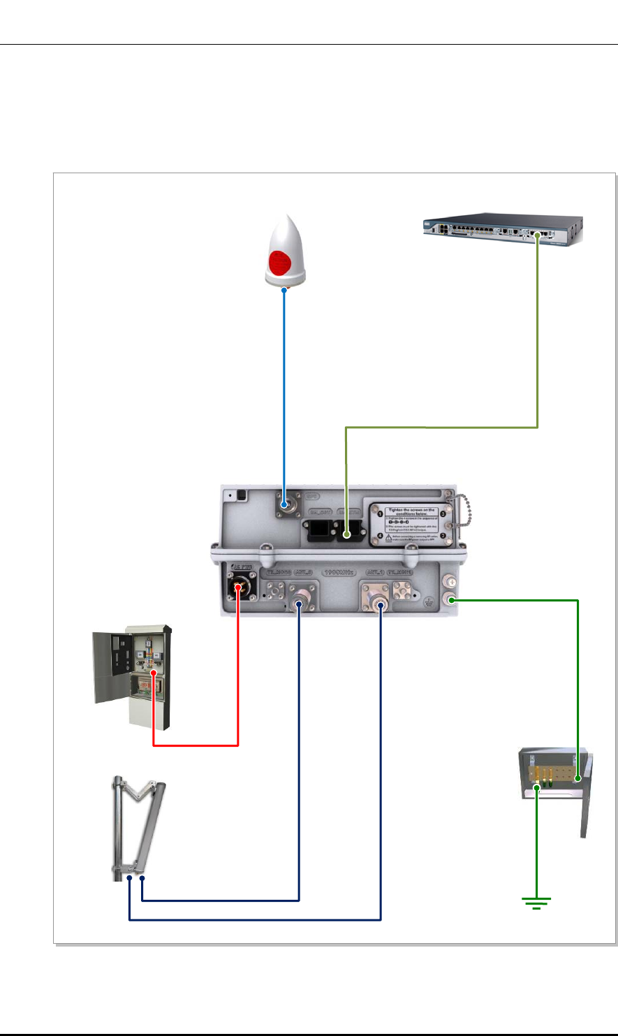
Figure 19. Cabling Diagram
5) RF Cable
[AC Distributor]
[MGB]
[RF Antenna]
1) Frame Ground Cable
[GPS Antenna] [Switch or Router]
2) Power Cable
3) Backhaul Cable(Copper)
4) GPS Cable
5) RF Cable

Ver.
CHAPTER 3. Connecting Cables
© SAMSUNG Electronics Co., Ltd. page 50 of 116
1.0
Table 19. Outdoor Pico Connection Cable
From To Cable
MGB Outdoor Pico 1) Frame Ground Cable
: AWG8, F-GV 6 mm2 × 1C
Outdoor Pico AC Distributor 2) Power Cable
: AWG14, F-FR-8 1.5 mm2 × 3C
Switch or Router 3) Backhaul Cable (Copper)
: S-FTP Cat.5e or Cat.6 4Pair #24
GPS Antenna 4) GPS Cable
: 1/2 in. Coaxial Cable
RF Antenna 5) RF Cable
: 1/2 in. Feeder Line

Ver.
CHAPTER 3. Connecting Cables
© SAMSUNG Electronics Co., Ltd. page 51 of 116
1.0
3.3 Grounding
Grounding is required for protecting complex electronic or electric systems such as power
system, communication system, and control system from lightning, over-current, over-
voltage, and electric noise. Thus, the systems can operate properly and protect human life
from electrical shock. Ground equipment minimizes the electrical potential of the electronic
device to that of the ground, which is zero electrical potential, so that it can prevent the
device from occurring electrification.
The purposes of the ground construction are as follows:
y To prevent human life and the system from over-current, over-voltage, and lightning
y To provide a discharge path for surge voltage generated by lightning and power switch
y To protect the system from static electricity
y To eliminate or minimize the high-frequency potential in the system housing
y To provide a conductor for the balance and stability of high-frequency current
y To stabilize the potential of the circuit against the ground
Connecting Ground Cable
In cabling, the connection of cables without the connection to the ground cable
may cause the damage of the equipment or the bodily injury of the worker.
Connect the ground cable first.
System Grounding Method
Ground bar for lightning protector/power/communication must be isolated from
each other. These three ground bars can be grounded as the isolation grounding
method, or branched from ground mesh buried in the underground as common
grounding method.
Ver.
CHAPTER 3. Connecting Cables
© SAMSUNG Electronics Co., Ltd. page 52 of 116
1.0
3.3.1 Grounding the Outdoor Pico
The way to connect the ground cable of Outdoor Pico is as follows:
Table 20. Grounding the Outdoor Pico
Category Description
Installation Section MGB~Outdoor Pico Grounding Terminal
Cable AWG8, F-GV 6 mm2 × 1C/1 EA
Heat Shrink Tube
(Spec/Color/Length)
Ф 0.63 in. (16 mm)/Green/2.76 in. (70 mm)
Pressure Terminal MGB Checking MGB specifications per site and preparing
connecting parts
Outdoor Pico 6 mm2, 2 Hole, 90°, Hole Dia.: 1/4 in. (6.3 mm), Hole
Dist.: 0.63 in. (16 mm)
Fastener MGB Checking MGB specifications per site and preparing
connecting parts
Outdoor Pico M6 × 12L SEMS/2 EA
Recommended Torque
Value
M6 SEMS 1.45 lbf·ft (20~30 kgf·cm)
Working Tools Cable Cutter, Wire Stripper, Compressor, Heating Gun, Torque Driver
(+), Torque Wrench, Nipper
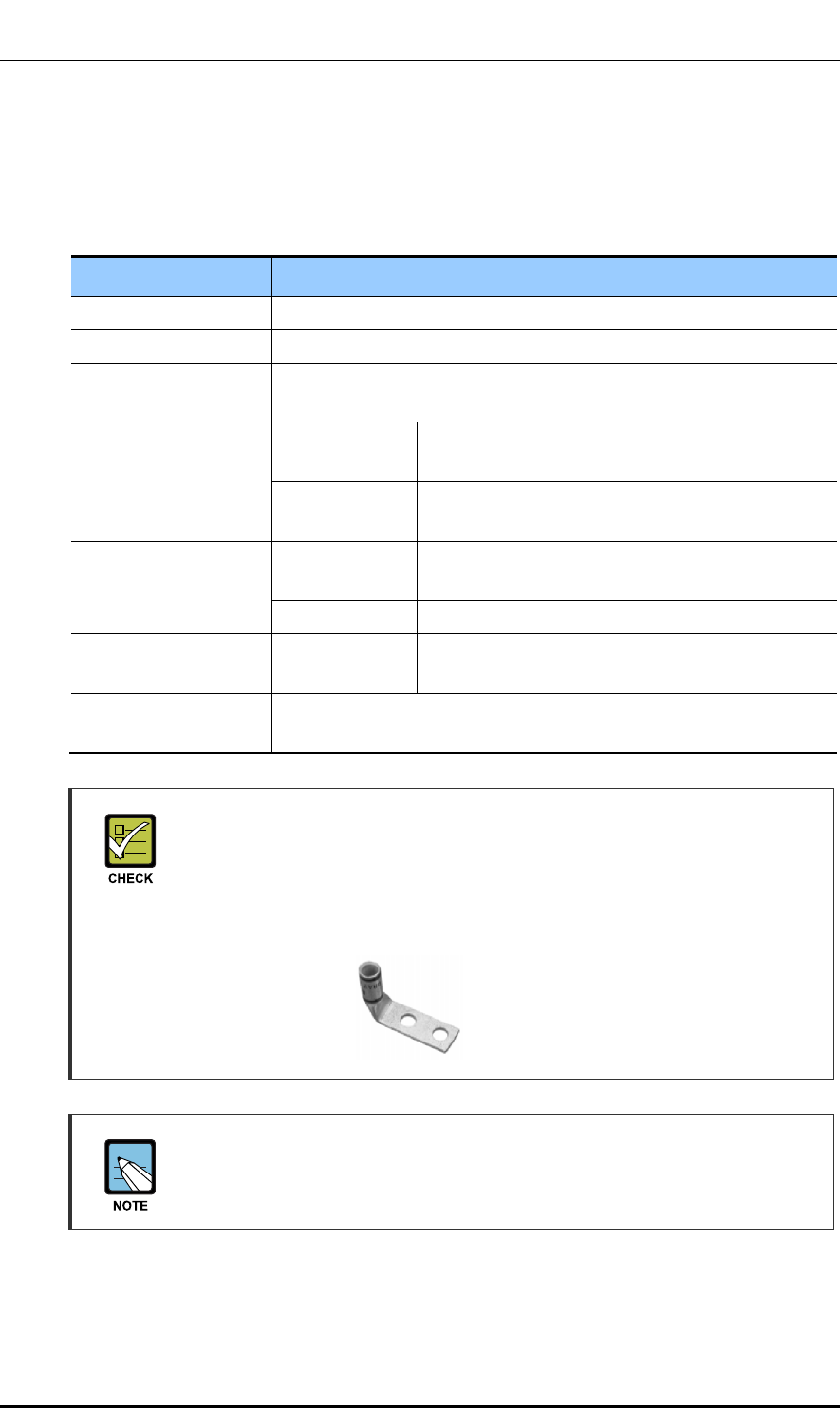
Pressure Terminal for Grounding
As for the pressure terminal or the cable, the UL certified products or equivalent
should be used.
Ex) Manufacturer: Panduit
Outdoor Pico: 6 mm2 Pressure Terminal (LCD8-14AF-L)
Assembling a Pressure Terminal and a Heat Shrink Tube
Refer to the ‘ANNEX F’ to see how to assemble a pressure terminal and a heat
shrink tube to a cable.
Ver.
CHAPTER 3. Connecting Cables
© SAMSUNG Electronics Co., Ltd. page 53 of 116
1.0
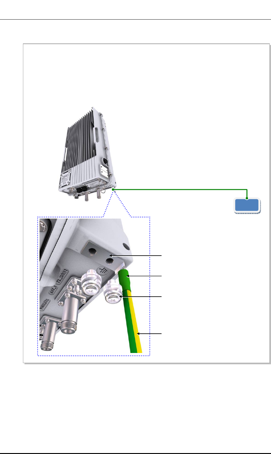
Figure 20. Connection of the Outdoor Pico Ground Cable
MGB
1) Install the ground cable from the MGB to the Outdoor Pico ground terminal.
2) Assemble a pressure terminal and a heat shrink tube at the end of the Outdoor Pico ground cable.
3) Align the pressure terminal assembled to a ground cable to the mounting hole of the Outdoor Pico
ground terminal.
4) Firmly fix the pressure terminal onto the Outdoor Pico ground terminal using fasteners.
Ground Cable (AWG8, F-GV 6 mm2 × 1C)
[Outdoor Pico]
M6 × 12L SEMS
Pressure Terminal
Ground Cable
Heat Shrink Tube (Green)
Ver.
CHAPTER 3. Connecting Cables
© SAMSUNG Electronics Co., Ltd. page 54 of 116
1.0
3.4 Power Cabling
The power supply is configured as follows.
Figure 21. Power Equipment Diagram
Turning Off the Circuit Breaker before Connecting the Power Cable
Since power is applied to the system where the power cable is connected by
manipulating the circuit breaker of the AC distributor, be sure to check the AC
distributor’s circuit breaker is turned off (open) before connecting the power cable
to the power connector. If the system is installed while the circuit breaker is on,
the worker may be critically injured as soon as the cable is connected in the
wrong way.
When Using Power Cables
- When handling the power cable, ensure the power switch of a rectifier or the
system is turned off to prevent the risk from the power cable and electric short-
circuit of related cables.
- Because a power accident may occur when fixing parts get loosened, make
sure that fasteners to fix the power cable should be firmly fastened.
- For supply connections, use wires suitable for at least 90 °C.
A
C
AC Distributor
(Uninterruptible Power)
Commercial Power System

Ver.
CHAPTER 3. Connecting Cables
© SAMSUNG Electronics Co., Ltd. page 55 of 116
1.0
3.4.1 Connecting the AC Power Cable
Follow the steps below to connect the AC power cable to the Outdoor Pico.
Table 21. Connecting the AC Power Cable
Category Description
Installation Section AC Distributor~Outdoor Pico Power Input Terminal
Cable L1 AWG14, F-FR-8
1.5 mm2 × 3C/1 EA
Red (Colorless and Red Band)
L2( or N) Black (Colorless and Black Band)
GND White (Colorless)
Heat Shrink Tube
(Spec/Color/Length)
L1 Ф 0.31 in. ( Ф 8 mm)/Red/1.18 in. (30 mm)
L2( or N) Ф 0.31 in. ( Ф 8 mm)/Black/1.18 in. (30 mm)
GND Ф 0.31 in. ( Ф 8 mm)/Green/1.18 in. (30 mm)
Junction Ф 0.59 in. (15 mm)/Black/1.97 in. (50 mm)
Connector AC Distributor Check the specification of AC distributor output terminal
and prepare fasteners.
Outdoor Pico SOURIAU/UTS6JC12-4S
Working Tools Cable Cutter, Wire Stripper, Compressor, Heating Gun, Torque Driver (+),
Torque Wrench, Nipper, Soldering Iron, and Lead
Ver.
CHAPTER 3. Connecting Cables
© SAMSUNG Electronics Co., Ltd. page 56 of 116
1.0
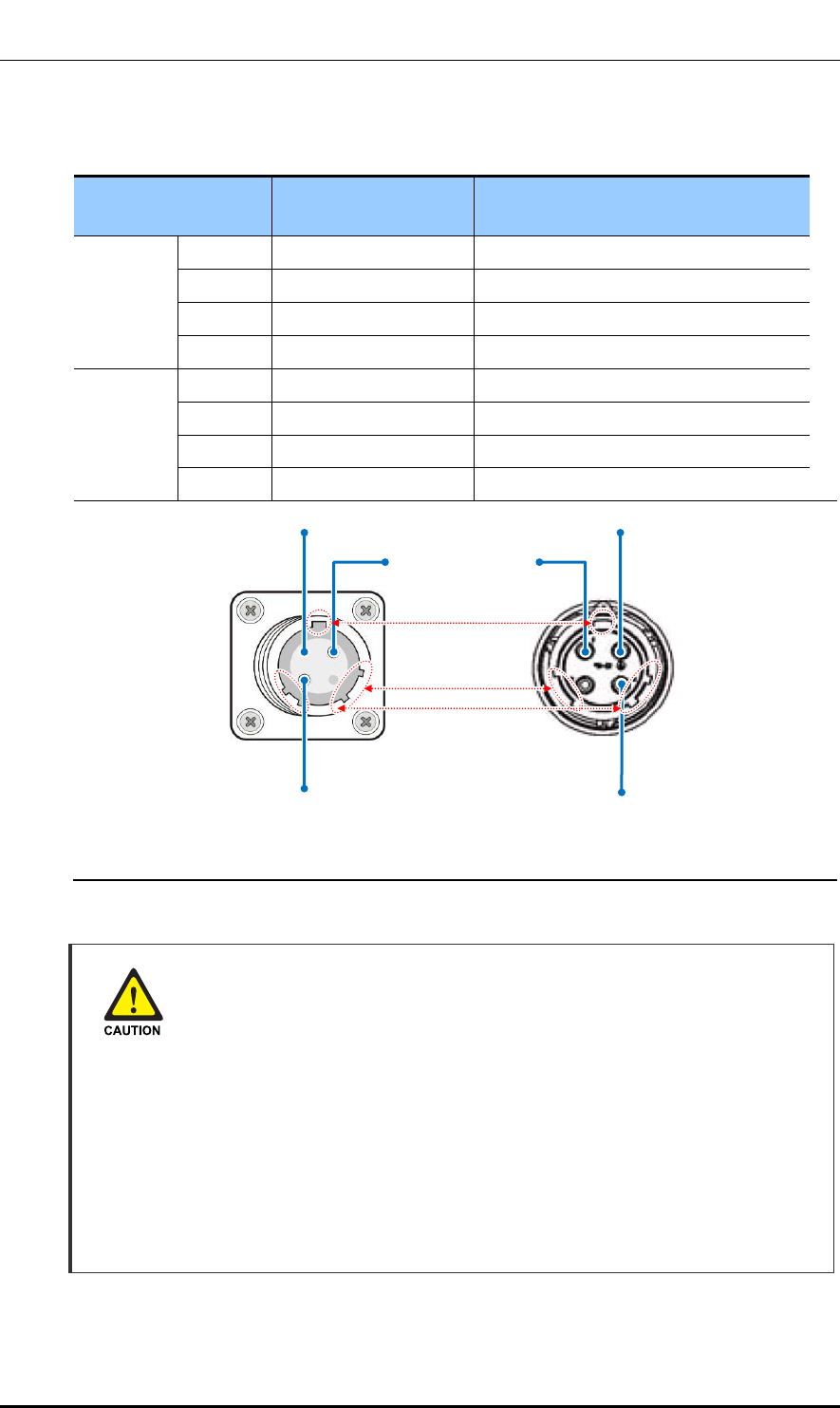
Table 22. Power Cable/Connector Pin Map
Power Connector
Pin No. Description Heat Shrink Tube
120 VAC 1 L1 Red
2 N.C -
3 N White
GND GND Green
240 VAC 1 L1 Red
2 N.C -
3 L2 Black
GND GND Green
AC Power cable
In case of using AC power cable (AWG 14, F-FR-8 1.5 mm2 × 3C), it is applicable up
to 721.8 ft (220 m). When the distance is 721.8 ft (220 m), followings should be
considered.
- Do not rapid ON/OFF (within one second): The voltage loss value caused by the
cable resistance, and the Outdoor Pico could be damaged by the counter
electromotive force caused by the cable inductance.
- Do not use the power cables linked: Using the power cables linked each other,
the loss will be increased.
- For the length of the AC power cable, follow the safety regulation of the
installation site.
1
GND GND
3 3
1
[Cable-side Connector:
UTS6JC12-4S]
[System-side Connector:
UTG012-4P]
Ver.
CHAPTER 3. Connecting Cables
© SAMSUNG Electronics Co., Ltd. page 57 of 116
1.0
Cautions When Connecting AC Power
When connecting the AC power cable to the L1-GND-L2, check the polarity of
each phase at the L1-GND-L2 single-phase connection area of AC power
distributor to ensure that correct polarity is connected to the L1-GND-L2 of the
system's input end. Check if the 120V-240 V between L1 and L2 is within the
allowable range (with tolerance of +/-10%).
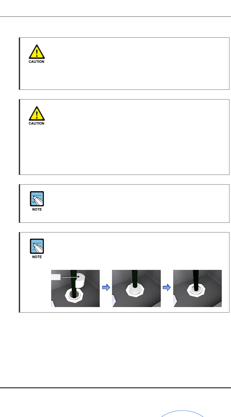
Finishing the System Input/output Port and Cable Inlet
To prevent foreign substances, outdoor air and moisture from entering the system
input/output port and cable inlet (including cable gland and conduit), finish it as
follows:
- Unused inlet
Use the hole finishing materials including waterproof cap and rubber packing.
- Cable-installed Port and Cable Inlet
After cable installation, block any space in the inlet with tape, compressed
sponge, rubber packing, and silicon.
Power Cable Color
In the table above, the cable color is based on local code that inner wire of F-FR-
8 × 3 core cable. The color of the inner wires may vary depending on the type and
manufacturer of the cable used.
Finishing the Holes on AC Distributor
When laying the power cable through the input/output port (conduit) at the bottom
of the AC distributor, a young board should be used to prevent foreign substances
from coming into the inside.
Young Board
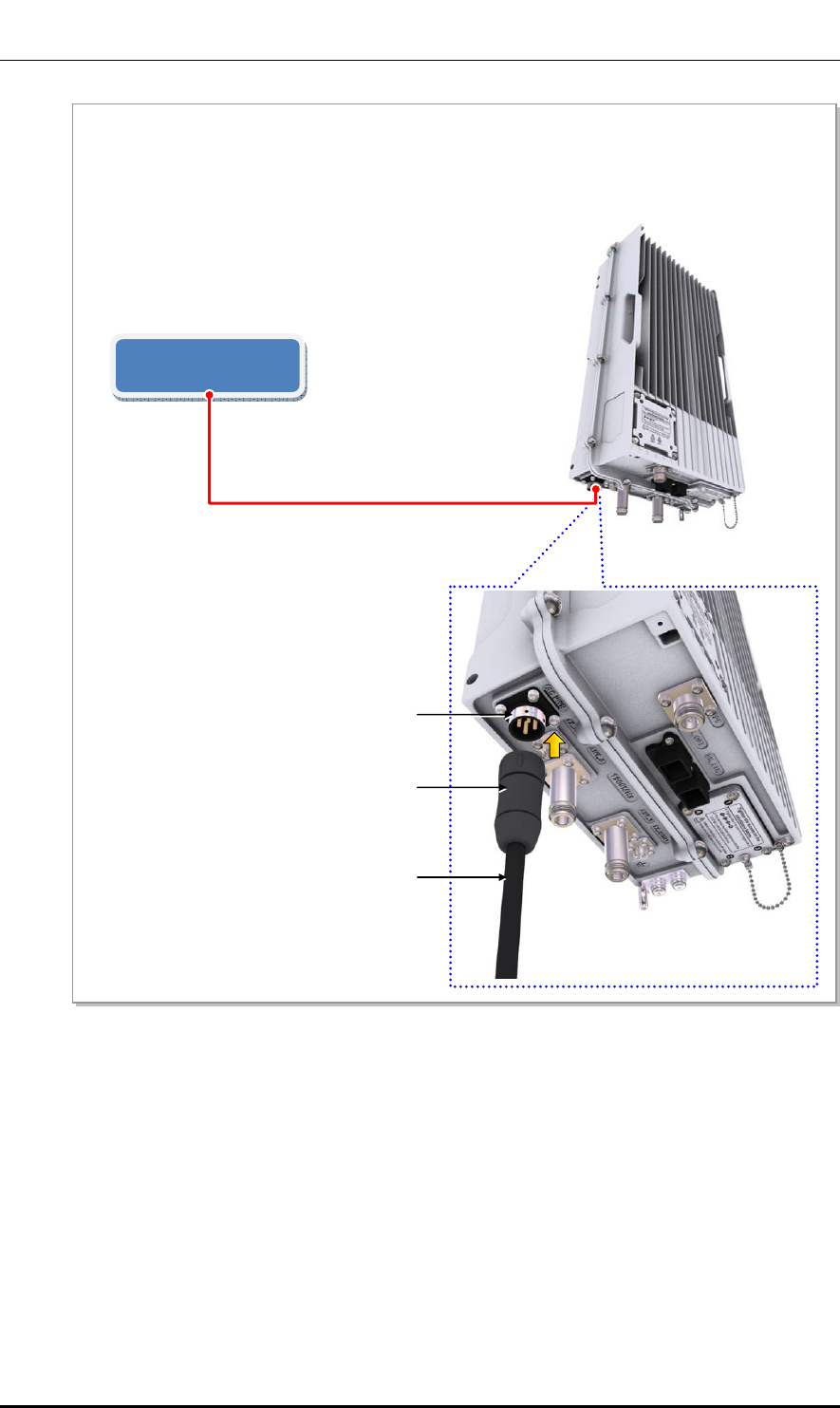
Ver.
CHAPTER 3. Connecting Cables
© SAMSUNG Electronics Co., Ltd. page 58 of 116
1.0
Figure 22. Connecting the Outdoor Pico Power Cable (1)
AC Distributor
(120~240 VAC)
1) Install a power cable from the AC distributor to the power input port (120-240 VAC) of the Outdoor
Pico.
2) Assemble a connector to the end of power cable (Outdoor Pico-side).
Power Cable (AWG14, F-FR-8 1.5 mm2 × 3C)
[Outdoor Pico]
Power Connecto
r
Power Cable
Power Input Port (120~240 VAC)
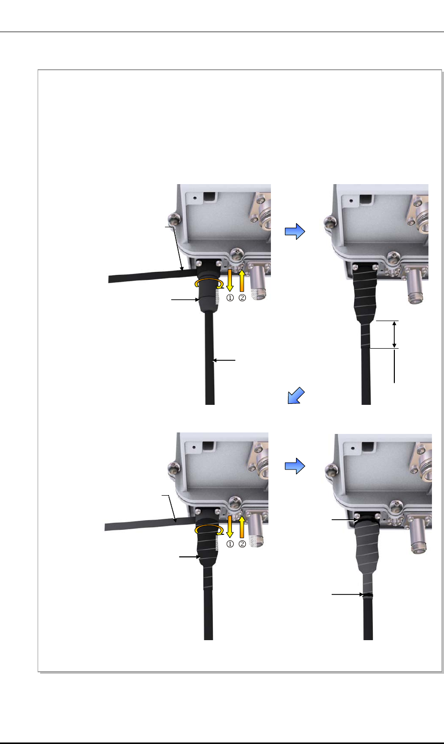
Ver.
CHAPTER 3. Connecting Cables
© SAMSUNG Electronics Co., Ltd. page 59 of 116
1.0
Figure 23. Connecting the Outdoor Pico Power Cable (2)
Power Connecto
r
A
C Input Power Cable
4) Once the connector is connected, wrap up the connector with a butyl tape two fold or more from 1.97
in. (50 mm) off the bottom to the system-side connector.
5) Wrap up the butyl taping section with insulation tape twofold or more in the same way as for the butyl
tape.
6) Bind the end of the insulation tape with a cable tie or apply bond or silicone to prevent it from
loosening.
Butyl Tape
1.97 in
(50 mm)
Butyl Tape
Cable Tie
Insulation Tape
Cable Tie
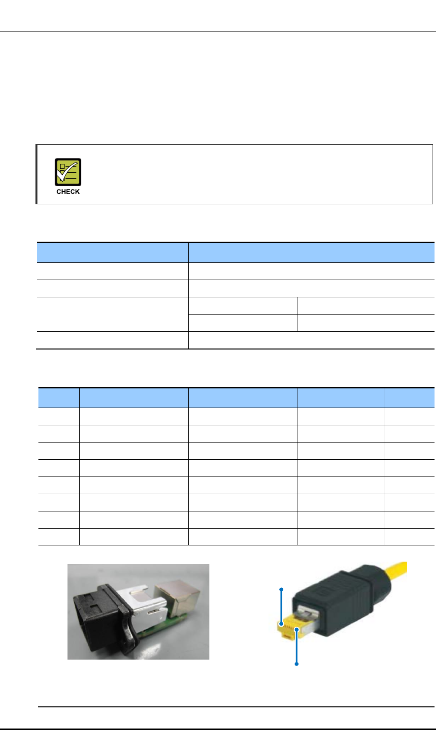
Ver.
CHAPTER 3. Connecting Cables
© SAMSUNG Electronics Co., Ltd. page 60 of 116
1.0
3.5 External Interface Construction
3.5.1 Backhaul Cable Connection
Follow the steps below to connect the backhaul cable (copper type) to the Outdoor Pico.
Checking Backhaul Cable Connection Type
The optic type and copper type have different parts and installation methods so
prepare installation after checking the type with a service provider.
Table 23. Table 3.6 Backhaul Cable Connection (Copper Type)
Category Description
Installation Section Switch or Router~Outdoor Pico_Backhaul (BH_ETH) Port
Cable S-FTP, Cat.5e or Cat.6, 4Pair, #24/for Outdoor
Connector Switch or Router RJ-45 (Shield Type)
Outdoor Pico Harting 0945 145 1560, RJ-45
Working Tools LAN Tool, LAN Tester, Nipper, Wire Stripper, and Cable Cutter
Table 24. Table 3.7 Backhaul Cable (Copper Type)/Connector Pin Map
Pin No. 10 Base-T/100 Base-TX 1000 Base-T Color Pair No.
1 Output signal positive BI Data 2 positive Orange/White 2
2 Output signal negative BI Data 2 negative Orange 2
3 Input signal positive BI Data 3 positive Green/White 3
4 N.C BI Data 1 positive Blue 1
5 N.C BI Data 1 negative Blue/White 1
6 Input signal negative BI Data 3 negative Green 3
7 N.C BI Data 4 positive Brown/White 4
8 N.C BI Data 4 negative Brown 4
[Cable-side Connector: Harting 0945 145 1560]
1
[System-side Connector: Harting 0945 245 1102 001]
8
Ver.
CHAPTER 3. Connecting Cables
© SAMSUNG Electronics Co., Ltd. page 61 of 116
1.0
Cautions When Assembling a Cable Connector
The pin map provided by this manual is based on the connectors on the system
side, so it is necessary to check the pin connection positions when connecting to
the cable side.
Finishing the System Input/output Port and Cable Inlet
To prevent foreign substances, outdoor air and moisture from entering the system
input/output port and cable inlet (including cable gland and conduit), finish it as
follows:
- Unused inlet
Use the hole finishing materials including waterproof cap and rubber packing.
- Cable-installed Port and Cable Inlet
After cable installation, block any space in the inlet with tape, compressed
sponge, rubber packing, and silicon.
Assembling the RJ-45 Connector
To see how to connect a RJ-45 connector to a cable, refer to ‘ANNEX D’.
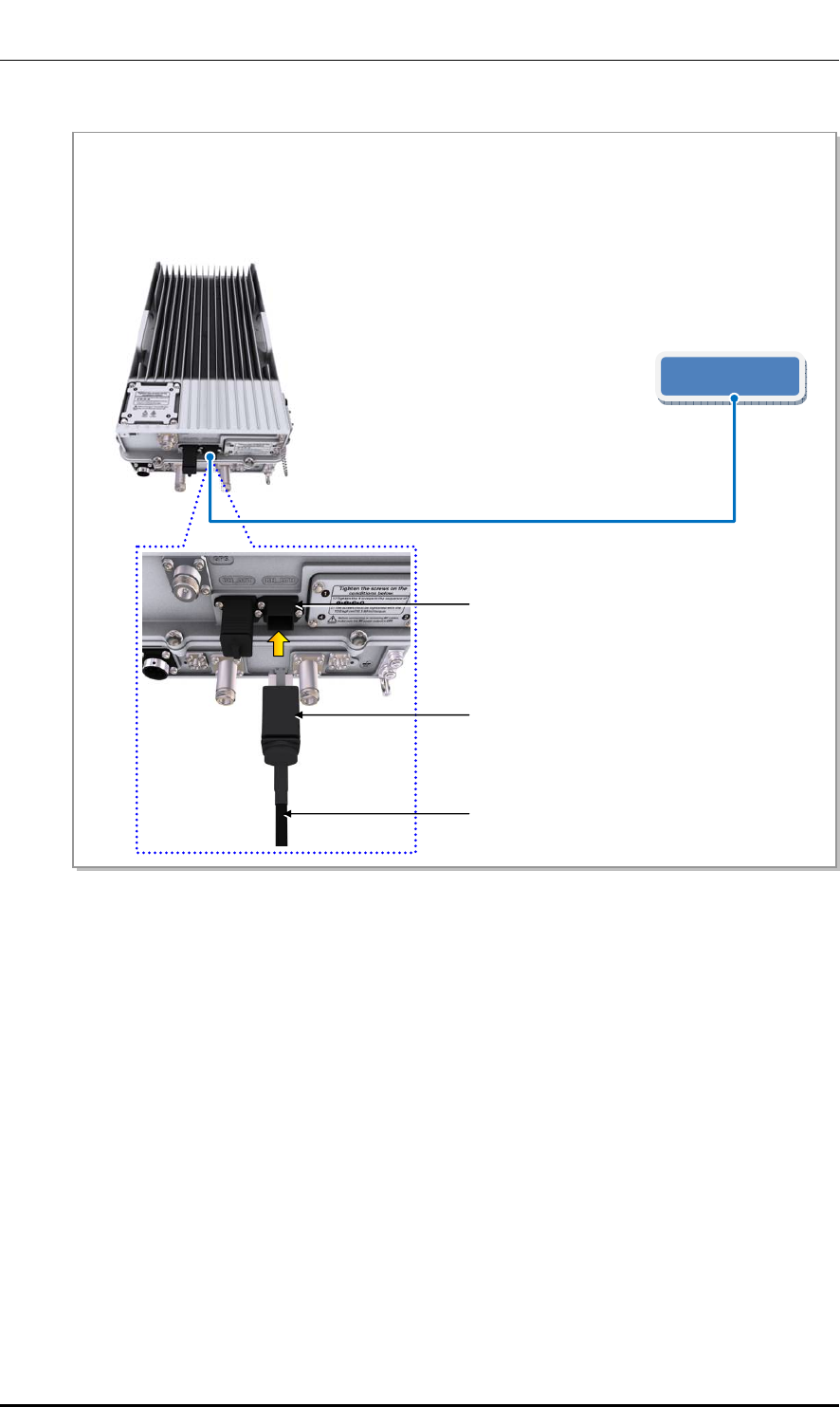
Ver.
CHAPTER 3. Connecting Cables
© SAMSUNG Electronics Co., Ltd. page 62 of 116
1.0
Figure 24. Backhaul Cable Connection_Copper Type
Switch or Router
1) Install a backhaul cable from the switch (or router) to the backhaul port (BH_ETH) of the Outdoor Pico.
2) Connect the connector of a backhaul cable to the backhaul port (BH_ETH) of the Outdoor Pico.
Backhaul Cable (S-FTP, Cat.5e or Cat.6, 4Pair, #24/Outdoor Type)
[Outdoor Pico]
Backhaul Connector (Copper Type)
Backhaul Cable (Copper Type)
Backhaul Por (Copper Type: BH_ETH)
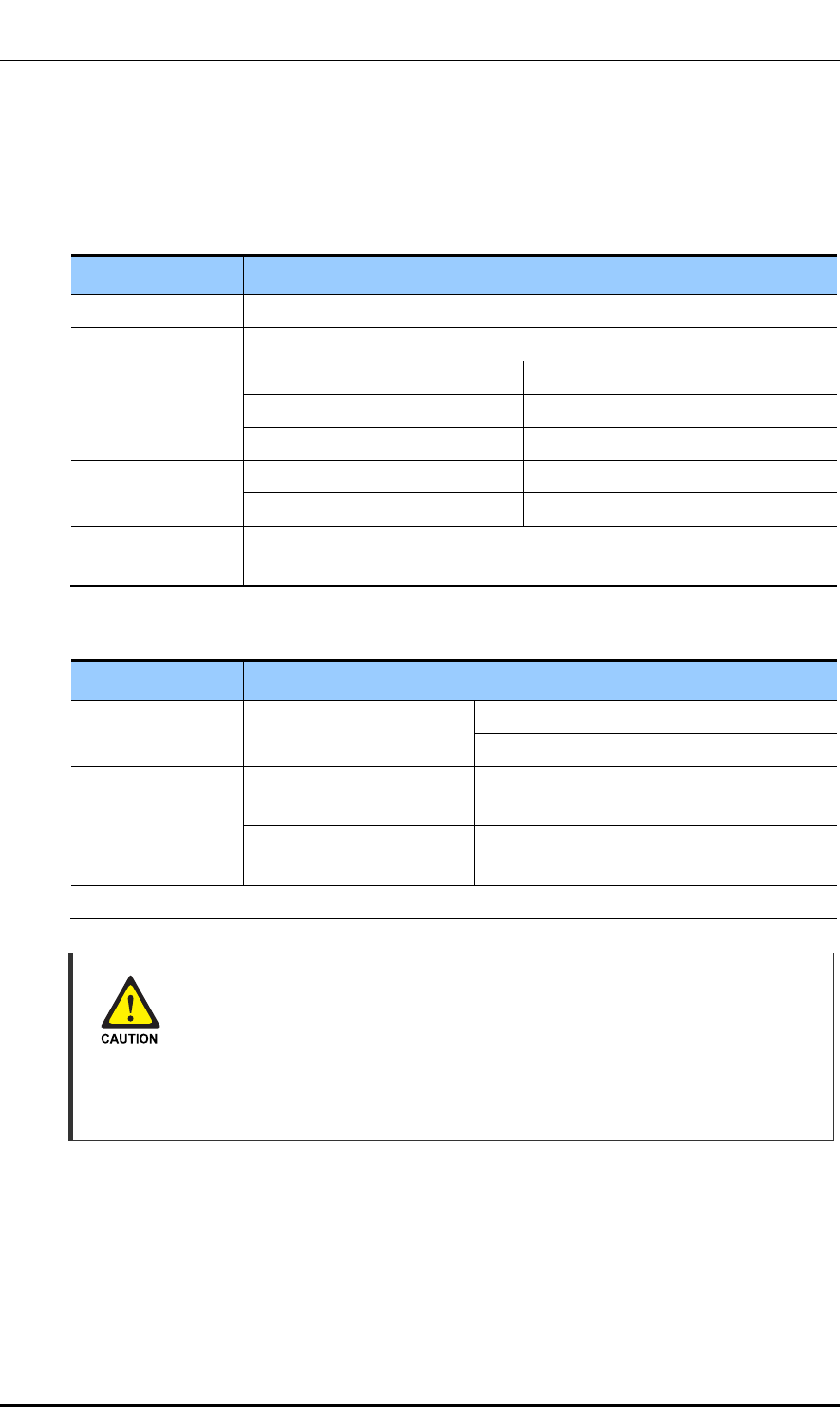
Ver.
CHAPTER 3. Connecting Cables
© SAMSUNG Electronics Co., Ltd. page 63 of 116
1.0
3.5.2 GPS Cable Connection
Follow the steps below to connect the GPS cable.
Table 25. GPS Cable Connection
Category Description
Installation Section Outdoor Pico~GPS Antenna
Cable 1/2 in. Coaxial Cable
Connector Outdoor Pico N Type-Male
Line Amplifier N Type-Male
GPS Antenna TNC-Male
Recommended
Torque Value
N Type-Male 1.45 lbf·ft (20 kgf·cm)
TNC-Male 0.65 lbf·ft (9 kgf·cm)
Working Tools Cable Cutter, Wire Stripper, Nipper, Torque Wrench, Spanner, Knife,
Soldering Iron, Lead
Table 26. GPS Cable Min. Radius of Curvature and Length Limitation
Category Description
GPS cable min.
radius of curvature
1/2 in. Coaxial Cable Installation 2 in. (50.8mm)
Repeated 5 in. (127 mm)
Length limitation of
GPS cable
When a line amplifier is not
used
1/2 in.
Coaxial Cable
98.42 ft. (30 m or less)
When using one line
amplifier
1/2 in.
Coaxial Cable
492.12 ft. (150 m or less)
※ When using Line Amplifier (Symmetricom/58529A) and GPS antenna (PCTEL, GPS-TMG-HR-26N’).
Cautions on the Min. Radius of Curvature of GPS Cable and Its Length
Limitation
If the GPS cable min. radius of curvature or its length limitation is violated, a GPS
signal may not be received seamlessly and it may cause abnormal system
operation. Therefore, the min. radius of curvature and length limitation of a GPS
cable proposed in the above table must be observed.
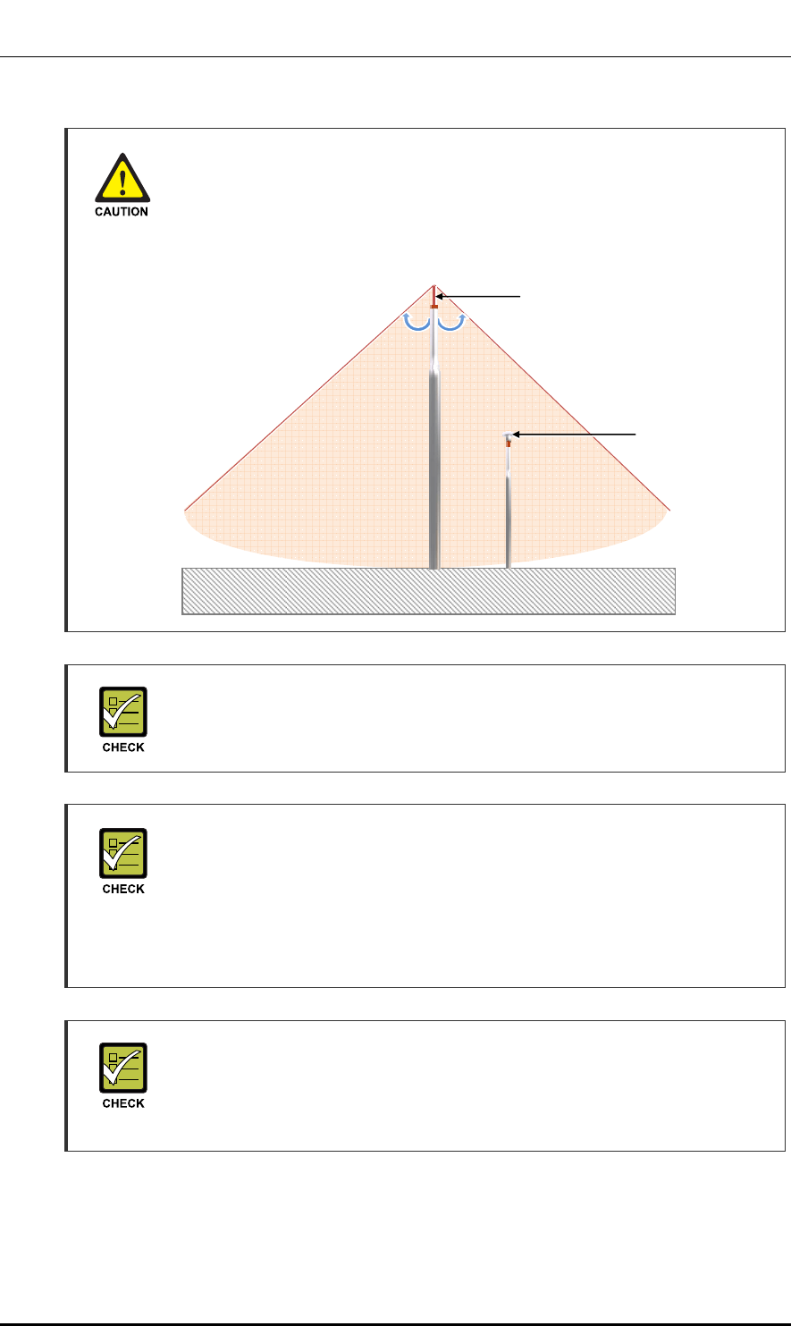
Ver.
CHAPTER 3. Connecting Cables
© SAMSUNG Electronics Co., Ltd. page 64 of 116
1.0
Installing the Antenna
When you install the antenna, the antenna must be within the protective angle
(left/right side 45° each from the central axis) to prevent the antenna from
lightning damage.
Installing GPS Antenna
When installing the GPS antenna, you must check the antenna installation
location, restriction and installing method in the ‘ANNEX A’.
Checking the Specifications of Antenna/Line Amplifier
Depending on the supplier or manufacturer of antenna/line amplifier the
connector type may be different. Also, the detail specifications of a connector may
be different depending on cable type even for the same connector type.
Therefore, check the detail specifications of a connector before preparing parts.
Ex) N Type-Male: for 1/2 in. Coaxial Cable
Specification of GPS Line Amplifier
GPS line amplifier specification is ‘Symmetricom-58529A’ or equivalent.
(‘http://www.symmetricom.com/products/gps-solutions/accessories/58529A-GPS-
Line-Amplifier-with-L1-Bandpass-Filter/’)
Lightning Rod
45° 45°
GPS Antenna
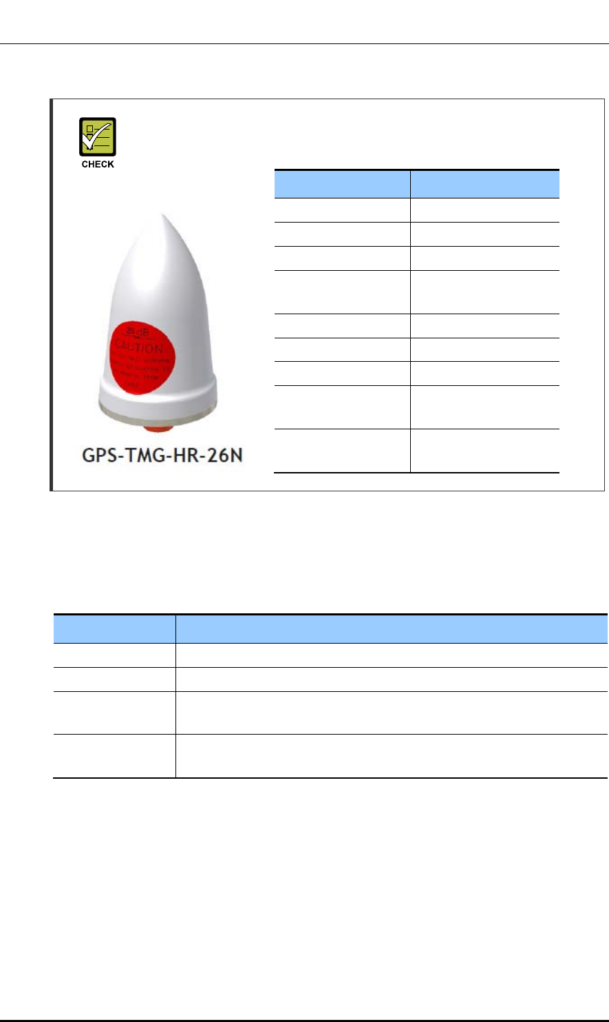
Ver.
CHAPTER 3. Connecting Cables
© SAMSUNG Electronics Co., Ltd. page 65 of 116
1.0
GPS Antenna Specifications
For GPS antenna, ‘PCTEL, GPS-TMG-HR-26N’ or equivalent must be used.
GPS Cable Identification Tag Installation
Attach the identification tape in the below table to the GPS cable.
Table 27. Identification Tag of GPS Cable
Classification Description
Installation position Attach the identification tag to the ends of GPS antenna and arrestor.
Materials Use the material of aluminum coated by vinyl for the identification tag.
Fixing method Fix the GPS cable to the 2 holes on the identification tag with the black
cable tie.
Identification
method
The markings must be prevented from being erased by using relief
engraving or coated labels.
Parameters Specifications
Frequency Band 1575.42 ± 1.2 MHz
Amplifier Gain 26.5 ± 3 dB
Output VSWR ≤ 2.0:1
Noise Figure
(including pre-selector)
≤ 4.0 dB @ +25°C(typ.)
≤ 4.5 dB @ +25°C(max.)
Operating DC Voltage 3.3~12.0 V(regulated)
Survival DC Voltage 24 V
DC Current ≤ 40 mA @ 5 V
Filtering 4-stage filtering including pre-
selector
Out of Band Rejection ≥ 65 dB @ 1559 MHz
≥ 65 dB @ 1625 MHz
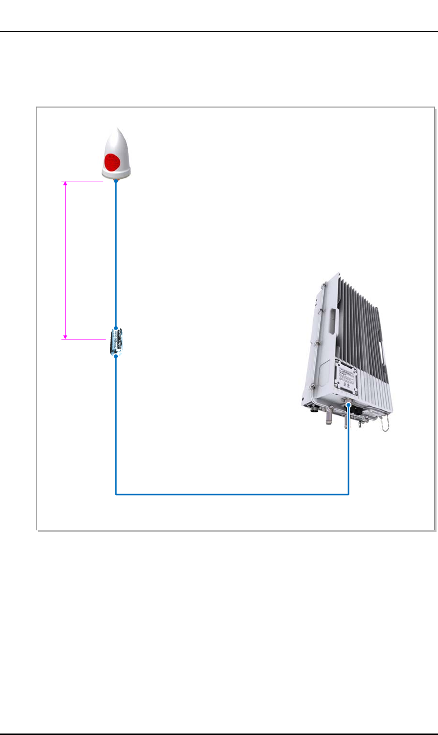
Ver.
CHAPTER 3. Connecting Cables
© SAMSUNG Electronics Co., Ltd. page 66 of 116
1.0
GPS Cable Configuration
The configuration of GPS cable is shown in the figure below.
Figure 25. GPS Cable Configuration
1/2 in. Coaxial Cable
(LDF4-50A or equivalent)
[Line Amplifier]
[GPS Antenna]
1/2 inch Coaxial cable
(Amplifier~GPS Antenna/Max. 32.80 ft,10 m)
[Outdoor Pico]
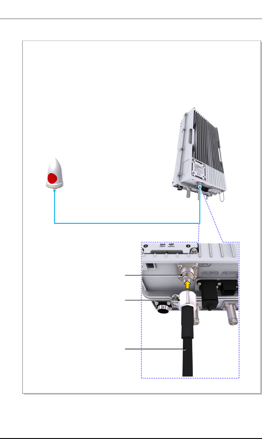
Ver.
CHAPTER 3. Connecting Cables
© SAMSUNG Electronics Co., Ltd. page 67 of 116
1.0
Figure 26. GPS Cable Connection (1)
[GPS Antenna]
1) Install a GPS cable (LMR-400) from the GPS port of the Outdoor Pico to the GPS antenna.
2) Assemble the connector to the GPS cable.
- Outdoor Pico-side Connector: N Type-Male
- GPS Antenna-side Connector: N Type-Male
3) Connect the N type male connector assembled to the end of the GPS cable to the GPS port of the
Outdoor Pico.
1/2 in. Coaxial Cable (LDF4-50A or equivalent)
[Outdoor Pico]
N Type-Male Connecto
r
GPS Cable
GPS Port
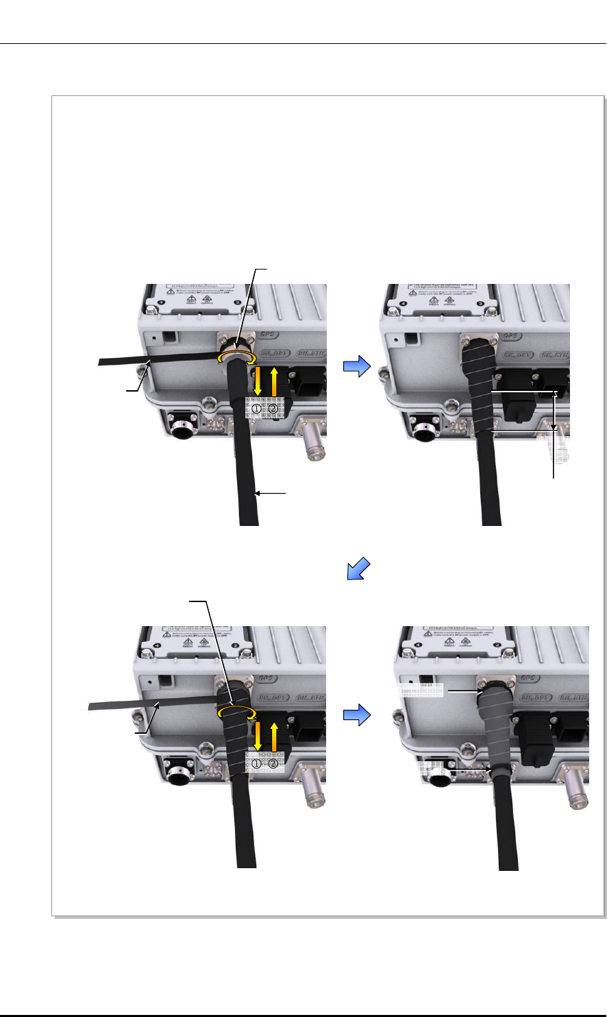
Ver.
CHAPTER 3. Connecting Cables
© SAMSUNG Electronics Co., Ltd. page 68 of 116
1.0
Figure 27. GPS Cable Connection (2)
1.97 in.
(50 mm)
N Type-Male Connector
1/2 in. Coaxial Cable
(LDF4-50A or equivalent)
Butyl Tape
Cable Tie
4) Once the connector is connected, wrap up the connector with a butyl tape two fold or more from 1.97
in. (50 mm) off the bottom to the system-side connector.
5) Wrap up the butyl taping section with insulation tape twofold or more in the same way as for the butyl
tape.
6) Bind the end of the insulation tape with a cable tie or apply bond or silicone to prevent it from
loosening.
Butyl Tape
Cable Tie
Insulation Tape
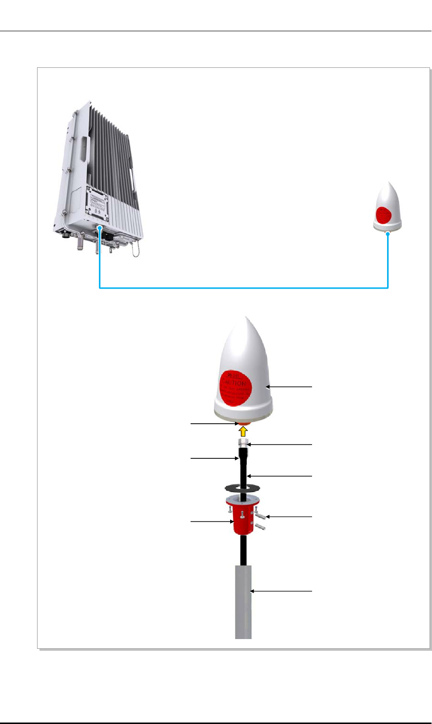
Ver.
CHAPTER 3. Connecting Cables
© SAMSUNG Electronics Co., Ltd. page 69 of 116
1.0
Figure 28. GPS Cable Connection (3)
7) Connect the N type-male connector (assembled to the end of GPS cable) to the GPS antenna port.
1/2 in. Coaxial Cable (LDF4-50A or equivalent)
[GPS Antenna]
[Outdoor Pico]
1/2 in. Coaxial Cable
(LDF4-50A or equivalent)
GPS 안테나
N Type-Female Port
Clamp
Heat Shrink Tube(Jelly Type)
Clamp fixing Screw
GPS 안테나 Fixing Pipe
N Type-Male Connector
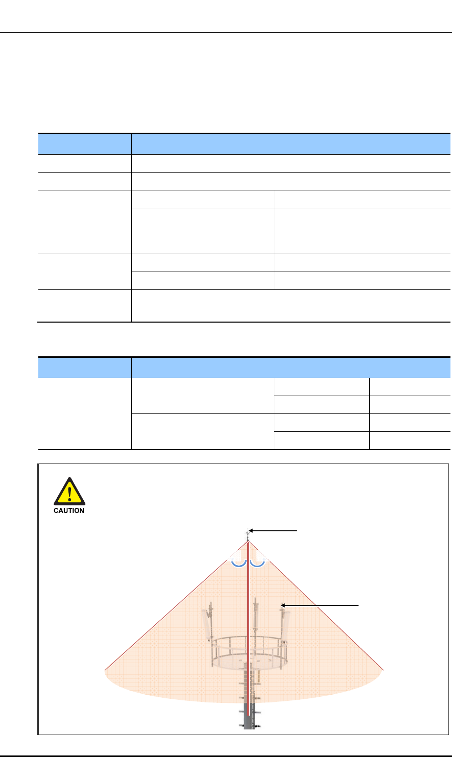
Ver.
CHAPTER 3. Connecting Cables
© SAMSUNG Electronics Co., Ltd. page 70 of 116
1.0
3.5.3 RF Cable Connection
Follow the steps below to connect the RF cable.
Table 28. RF Cable Connection
Category Description
Installation Section Outdoor Pico RF Antenna Port (ANT)~RF Antenna
Cable 1/2 in. Feeder Line
Connector Outdoor Pico N Type-Male
RF Antenna N Type-Male
(Checking RF antenna specifications
and preparing connector)
Recommended
Torque Value
N Type-Male 1.45 lbf·ft (20 kgf·cm)
Din Type-Male 14.46 lbf·ft (200 kgf·cm)
Working Tools Cable Cutter, Wire Stripper, Nipper, Torque Wrench, Spanner, Knife,
Soldering Iron, Lead
Table 29. RF Cable Min. Radius of Curvature
Category Description
RF cable min.
radius of curvature
1/2 in. Feeder Line (for Indoor) LS/HFSC-12D 1.26 in.(32 mm)
RFS/SCF-12-50 1.26 in.(32 mm)
1/2 in. Feeder Line (for Outdoor) LS/HFC-12D 4.92 in.(125 mm)
RFS/LCF12-50 4.92 in.(125 mm)
Installing the Antenna
When you install the antenna, the antenna must be within the protective angle
(left/right side 45° each from the central axis) to prevent the antenna from
lightning damage.
Lightning Rod
45°45°
RF Antenna
Ver.
CHAPTER 3. Connecting Cables
© SAMSUNG Electronics Co., Ltd. page 71 of 116
1.0
Checking RF Cable Connection
After connecting the RF cables, perform the continuity test and feeder cable return loss to
check if the RF cable is changed and measure VSWR of antenna and RF cable.
Measure all cables of section ~. The measured VSWR should be the specification
value or less. If the VSWR exceeds the specification value, disassemble the connector and
measure each section separately.
Checking VSWR for Minimum Cable Bend Radius and Length of RF Cable
If the VSWR value for minimum cable bend radius and length of RF cable is not
applied, system may not work properly because RF signals cannot transmit or
receive smoothly. So, the VSWR value for minimum cable bend radius and length
of RF cable must be checked and applied.
Cautions When Measuring VSWR
When measuring VSWR, if you open the antenna port when the transmission
output is not completely off, a spike signal may flow into the reception path, which
may cause damage to LNA. Make sure the transmission output is completely off
when measuring VSWR.
Cautions When Connecting Feeder Lines
If you install the feeder line which is connected to the system, it may damage the
system and cable connection. Therefore, it is recommended to install the feeder
line up to the system's input port before connecting the feeder line to the system.
Checking the Specifications of Antenna Connector
Depending on the supplier or manufacturer of antenna, the connector type may
be different. Also, the detail specifications of a connector may be different
depending on cable type even for the same connector type.
Therefore, check the detail specifications of a connector before preparing parts.
Ex) Din Type-Male: for 1/2 in. Feeder line, for 7/8 in. Feeder Line
Connection Part of System External
Interface Connector Antenna
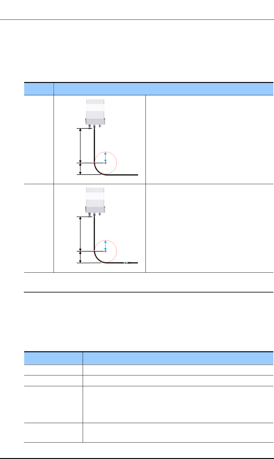
Ver.
CHAPTER 3. Connecting Cables
© SAMSUNG Electronics Co., Ltd. page 72 of 116
1.0
RF Cable Configuration
The RF cable is connected in the following two methods. Prepare and install parts based on
the method agreed by a service provider or the site conditions.
Table 30. RF Cable Connection at Antenna Connection Area
Case Description
Case #1
Connect a 7/8 in. or longer feeder line directly to
the RF antenna.
- If a space for min. radius of curvature can be
secured when a 7/8 in. or longer feeder line is used.
- If no excessive force is applied to the connector
assembled to the antenna port or cable because
the straight cable section is long enough.
Case #2
Connect a 1/2 in. feeder line (jumper cable) to
the RF antenna.
- If a space for min. radius of curvature cannot be
secured when a 7/8 in. or longer feeder line is used.
- If excessive force is applied to the connector
assembled to the antenna port or cable and it may
cause poor contact or damage because the
straight cable section is not long enough.
※ 7/8 in. or longer feeder line: 7/8 in./1 1/4 in./1 5/8 in. feeder line, etc.
※ The RF cable must be connected based on the method agreed by a provider or the site conditions.
RF Cable Identification Tag Installation
Attach the identification tape in the below table to the RF cable.
Table 31. RF Cable Identification Tag
Category Description
Installation position Attach the identification tag to the both ends of the antenna.
Materials Use the material of aluminum coated by vinyl for the identification tag.
Fixing method - Antenna side: Attach the tag to the feeder line using binding strings
through the two holes on the tag.
- Equipment Side: Cover up the feeder line with the tag and fix it using
binding strings through the two holes on the tag.
Identification method The markings must be prevented from being erased by using relief
engraving or coated labels.
Straight cable
section
Min. radius
of curvature
R’
RF Antenna
Straight cable
section
Min. radius
of curvature
R’
RF Antenna
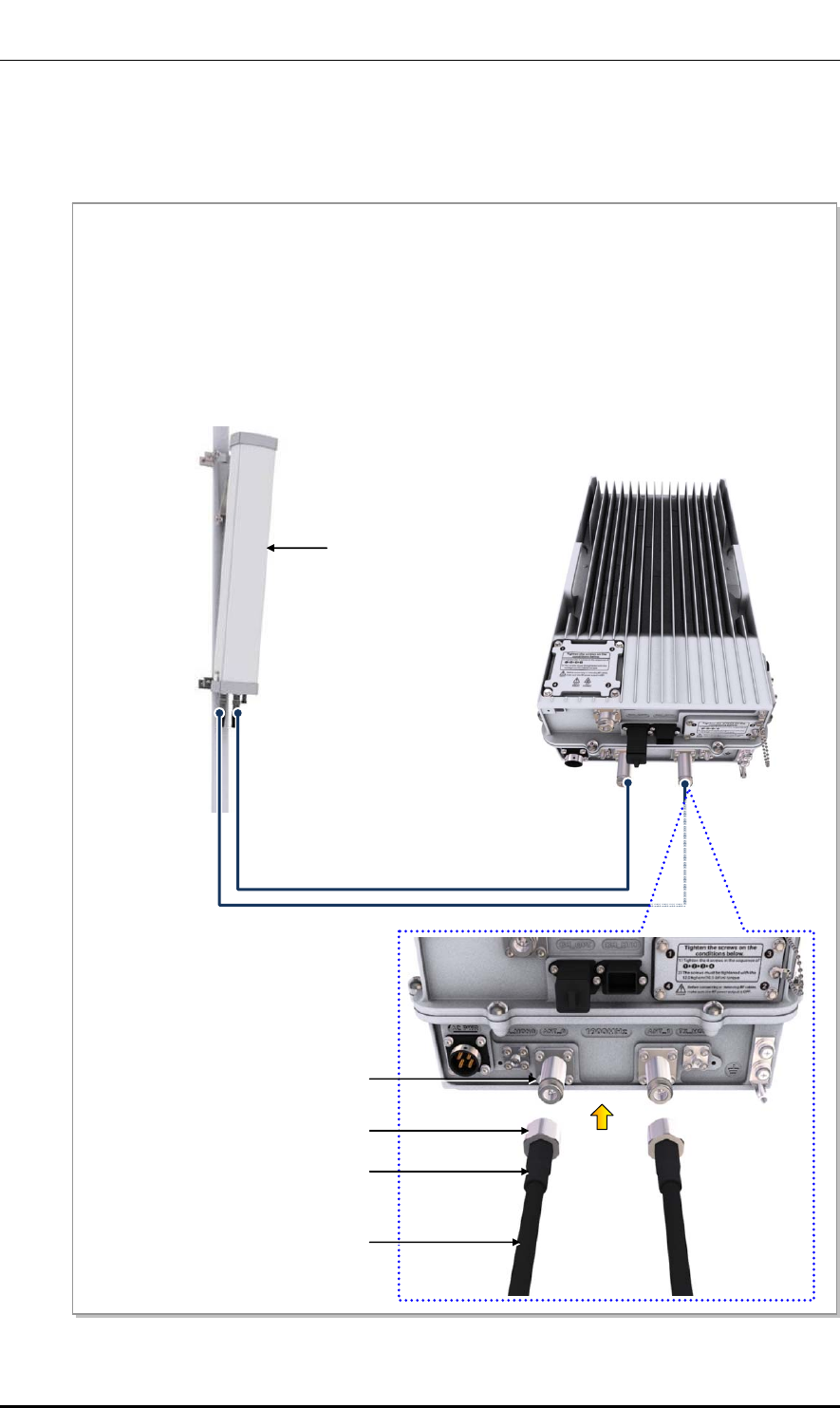
Ver.
CHAPTER 3. Connecting Cables
© SAMSUNG Electronics Co., Ltd. page 73 of 116
1.0
RF Cable Connection
Follow the steps below to connect the cable between Outdoor Pico and RF antenna.
Figure 29. RF Cable Connection (1)
RF Antenna
RF Cable (1/2 in. Feeder Line)
[Outdoor Pico]
1) Connect the connectors to the RF ports (N type-female) at the bottom of Outdoor Pico.
2) Assemble a connector at the end of the RF cable. (The specifications of the antenna and supplier-
specific connector, and the tightening method are subject to change.)
- Outdoor Pico-side Connector: N Type-Male
- RF Antenna-side Connector: N Type-Male
3) Connect the connector assembled at the end of the RF cable (Outdoor Pico-side) to the RF antenna
port of the Outdoor Pico.
N Type-Male Connecto
r
RF Cable
RF Antenna Port
Heat Shrink Tube
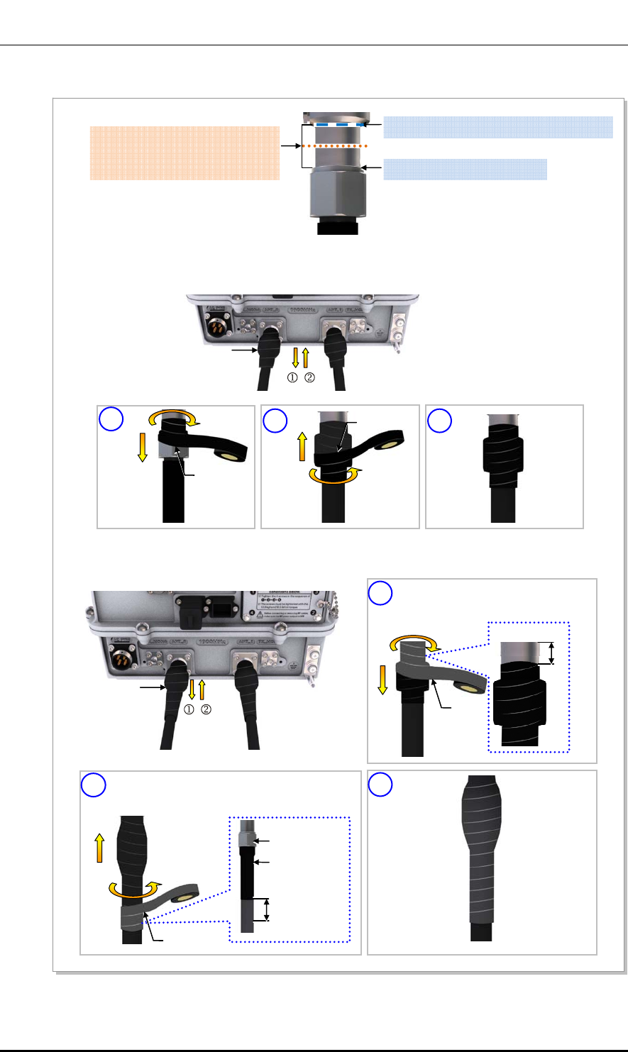
Ver.
CHAPTER 3. Connecting Cables
© SAMSUNG Electronics Co., Ltd. page 74 of 116
1.0
Figure 30. RF Cable Connection (2)
(1) Starting and Ending points of Butyl tape
Starting and Ending points of
Insulation Tape
[Mid-point between (1) and (2)] (2) Top side of Connector Nut
4) After connecting a connector, wrap the cable from the system-side connector using insulation tape
more than twice so that the metal parts of connection parts are not shown.
Insulation Tape
5) Wrap around the cables using butyl tape more than twice on the wrapped insulation tape.
Butyl Tape
2 3
Insulation
Tape
1 Insulation
Tape
2
Butyl
Tape
1
Butyl Tape
10~20mm
Start wrapping from the 10~20 mm
higher point than the insulation tape
wrapped.
Wrap to the 10~20 mm lower point than the end
of heat shrink tube for connector nut.
Heat shrink
tube
Connector Nut
10
[Bottom
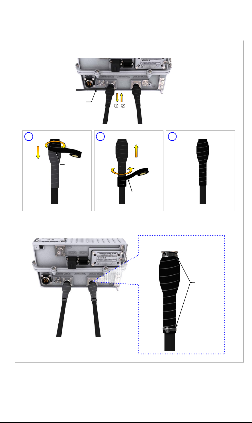
Ver.
CHAPTER 3. Connecting Cables
© SAMSUNG Electronics Co., Ltd. page 75 of 116
1.0
Figure 31. RF Cable Connection (3)
6) Wrap around the cable using insulation tape more than twice on the wrapped butyl tape.
Insulation Tape
2 3
Insulation
Tape
1
7) Bind cable ties at the both ends of insulation tapes not to be released.
Cable Tie
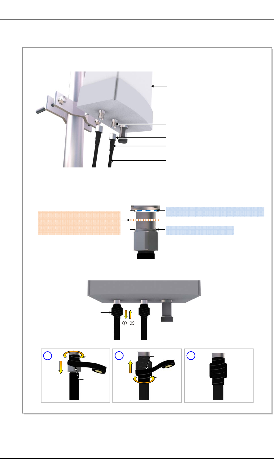
Ver.
CHAPTER 3. Connecting Cables
© SAMSUNG Electronics Co., Ltd. page 76 of 116
1.0
Figure 32. RF Cable Connection (4)
RF Antenna
8) Connect the connector (assembled to the end of the cable on the RF antenna side) to the RF antenna
port.
RF Antenna Input Port
Heat Shrink Tube(Jelly Type)
Din Type-Male Connector
RF Cable
9) After connecting a connector, wrap the cable from the system-side connector using insulation tape
more than twice so that the metal parts of connection parts are not shown.
Insulation Tape
(1) Starting and Ending points of Butyl tape
Starting and Ending points of
Insulation Tape
[Mid-point between (1) and (2)] (2) Top side of Connector Nut
2
3
Insulation
Tape
1
Insulation
Tape
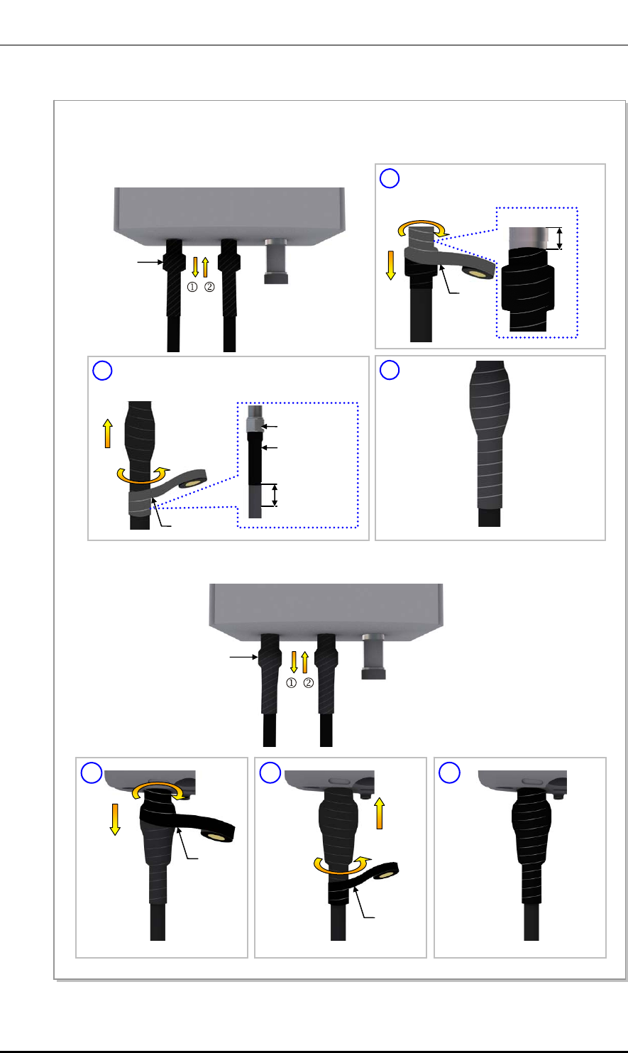
Ver.
CHAPTER 3. Connecting Cables
© SAMSUNG Electronics Co., Ltd. page 77 of 116
1.0
Figure 33. RF Cable Connection (5)
Butyl Tape
10) Wrap around the cables using butyl tape more than twice on the wrapped insulation tape.
11) Wrap around the cable using insulation tape more than twice on the wrapped butyl tape.
Insulation Tape
2
Butyl
Tape
1
Butyl Tape
10~20mm
Start wrapping from the 10~20 mm
higher point than the insulation tape
wrapped.
Wrap to the 10~20 mm lower point than the end
of heat shrink tube for connector nut.
3
Heat shrink
tube
Connector Nut
3
2 3
Insulation
Tape
1
Insulation
Tape
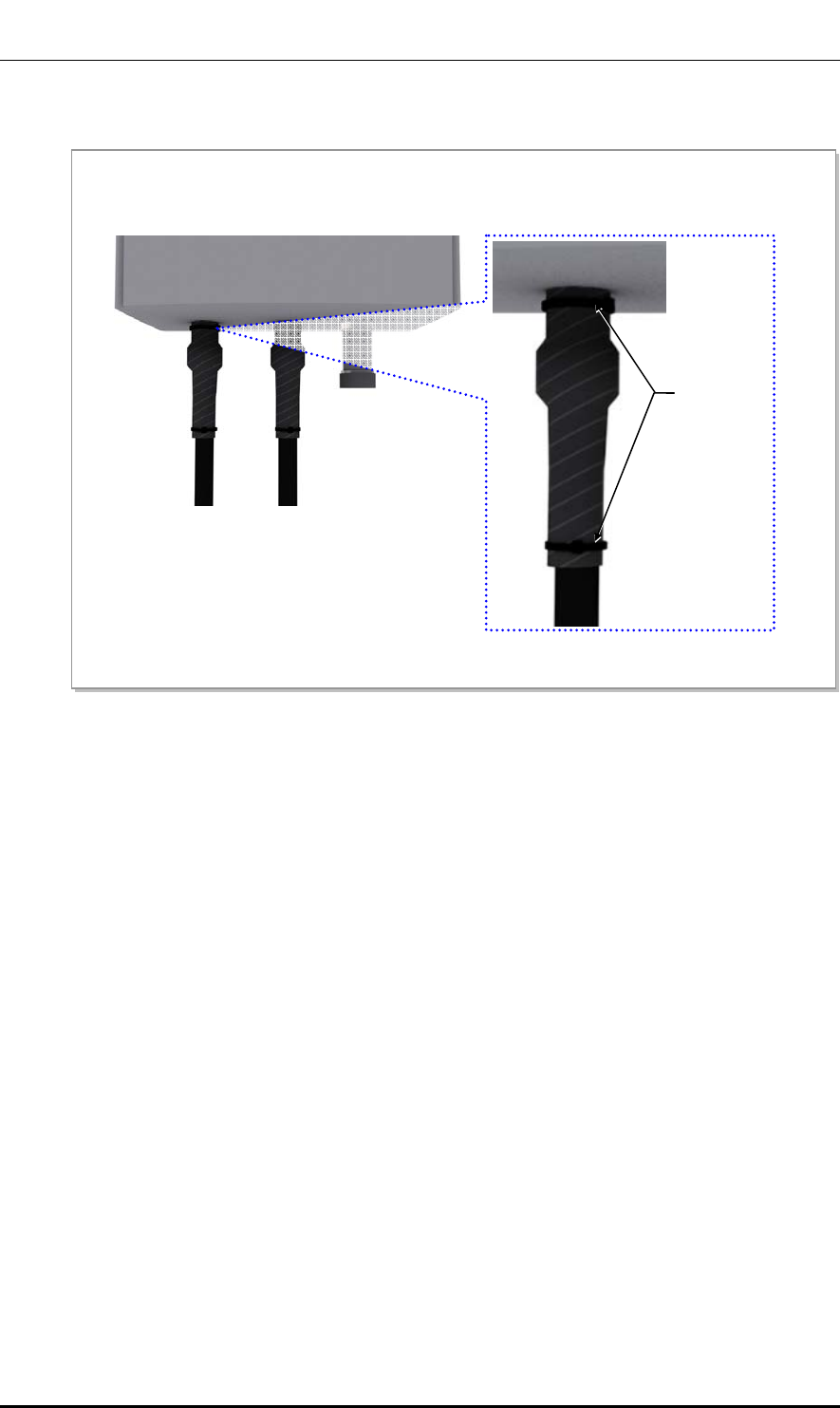
Ver.
CHAPTER 3. Connecting Cables
© SAMSUNG Electronics Co., Ltd. page 78 of 116
1.0
Figure 34. RF Cable Connection (6)
12) Bind cable ties at the both ends of insulation tapes not to be released.
Cable Tie
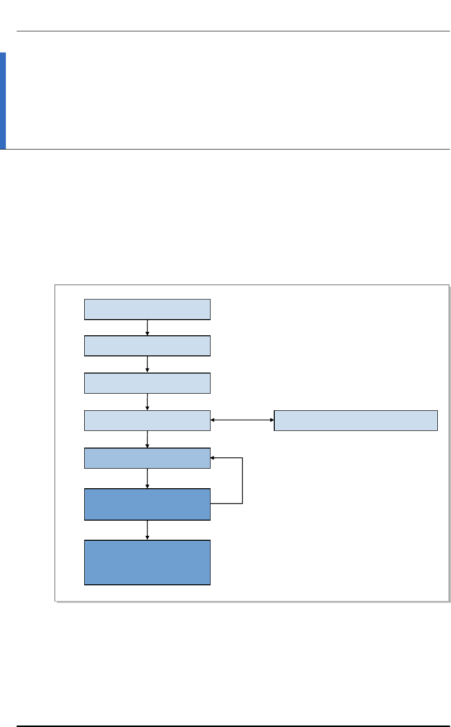
Ver.
CHAPTER 4. Checking Installation Status
© SAMSUNG Electronics Co., Ltd. page 79 of 116
1.0
CHAPTER 4. Checking Installation
Status
4.1 Installation Checking Procedure
Below is the procedure to check installation status.
Figure 35. Installation Checking Procedure
No
Yes
Sharing Inspection Results
Taking Corrective Actions
Checking the Results of
Corrective Actions
On-site Inspection
Inspection Checklist
Inspection Checklist/Corrective Actions
Sharing the Results of
Corrective Actions and
Preparing Preventive Plan
Inspection Plan

Ver.
CHAPTER 4. Checking Installation Status
© SAMSUNG Electronics Co., Ltd. page 80 of 116
1.0
Inspection Plan
Create an inspection sheet per system and select an inspector to set an inspection schedule
per site.
On-site Inspection and Inspection Checklist
The on-site inspection is to perform inspection visually or using instruments for each
specification, standard, and installation status, etc. based on the inspection checklist
actually at a site where the system ins installed.
The inspector must record the results onto the inspection checklist during or after filed
inspection.
Sharing Inspection Results and Taking Corrective Actions
The inspector must share the inspection results (inspection checklist/corrective actions)
with a installation operator and the installation operator must take the corrective actions if
necessary after reviewing the requirements.
Checking the Results of Corrective Actions
The inspector must check if the corrective actions are properly taken. If they are not sufficient,
the inspector must ask the installation operator to take the corrective actions again.
Sharing the Results of Corrective Actions and Preparing Preventive Plan
After the corrective actions are all completed, the inspector must share the results with the
installation operator and relevant departments and prepare a preventive plan to prevent the
same or similar problems from re-occurring.
Table 32. Construction Situation Checklist
Category Check Items Criteria Result
Pass Fail
Installing
Equipment
Appearance of equipment and
mechanical parts
Equipment damage such as Dent,
scratch and crack, etc.
Placement of equipment and
mechanical parts
Maintenance and horizontal/vertical
placement
Leveling condition of equipment
and mechanical parts
Horizontal/vertical fixing
(level, weight, rubber hose, etc.)
Validity of status and
specifications of tightening
bolt/nut/washer, etc.
Visual inspection and magnet check
Compliance with tightening torque
value
Other works (cable duct
installation status, etc.)
Checking position and installation
status
Grounding Status of ground bar
installation per usage
Checking the separation of
communication/power/lightning
grounding
Cable Size Checking specifications such as
thickness, etc.

Ver.
CHAPTER 4. Checking Installation Status
© SAMSUNG Electronics Co., Ltd. page 81 of 116
1.0
Category Check Items Criteria Result
Pass Fail
Cabling and binding status Cable damage/properness
installation route
Checking binding interval and the
condition of used materials
Cable connection Assembly and tightening condition
of a pressure terminal
Checking compliance with
tightening torque value
Installation status of cable tag Checking position, marking, and tag
installation type
Power Installation status of power
supply and circuit breaker
Power supply capacity/input voltage
(tester)
Checking circuit breaker type and
capacity
Cable Size Checking thickness and length
limitation
Cabling and binding status Cable damage/properness
installation route
Checking binding interval and the
condition of used materials
Cable connection Cable damage/properness
installation route
Checking binding interval and the
condition of used materials
Installation status of cable tag Checking position, marking, and tag
installation type
Other data
cables
Cable size Checking cable specifications per
usage
Cabling and binding status Checking cable
damage/properness installation
route, binding distance and
condition of used materials
Cable connection Checking cable connection (Pin Map),
assembly and tightening status of a
connector and compliance with
tightening torque value
Installation status of cable tag Checking position, marking, and tag
installation type
RF/GPS GPS signal reception status
(number of GPS reception
satellites)
More than 6 reception satellites (C/N
40 or higher)
Checking in-band or out-band jamming
Antenna installation status Checking specifications, installation
position, fixing status, and gap
between antennas

Ver.
CHAPTER 4. Checking Installation Status
© SAMSUNG Electronics Co., Ltd. page 82 of 116
1.0
Category Check Items Criteria Result
Pass Fail
Installation status of arrestor/
line amplifier/ splitter, etc.
Checking specifications, installation
position, and fixing status
Cabling and binding status Checking cable damage/properness of
installation route/binding distance and
the condition of used materials
Cable connection Checking cable connection status,
connector assembly and tightening
status, compliance with tightening
torque value, and finishing
Installation of cable tag Checking position, marking, and tag
installation type
Others Reserved ports and cable
inlet status
Finishing (Water-proof cap, etc.)
Connection of equipment I/O
port (Conduit/Cable Gland)
Checking tightening status
Installation of cable installation
route
Installation of cable tray and duct,
etc.
Status of inside/outside of the
equipment and system
surrounding area
Checking the stocking condition of
waste parts, waste materials,
packing materials, etc.
Opinion
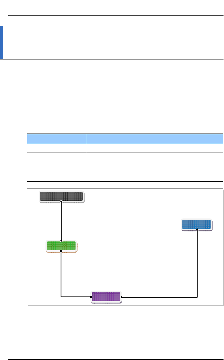
Ver.
ANNEX A. GPS Antenna Installation
© SAMSUNG Electronics Co., Ltd. page 83 of 116
2600-00FOTGGAA 6.0
ANNEX A. GPS Antenna Installation
A.1 GPS Antenna System Configuration
The GPS antenna system is commonly configured as shown below:
Table 33. GPS Antenna System Configuration
Category Description
GPS Antenna Device receiving a signal from a GPS satellite
GPS Line amplifier (Option) Device amplifying the GPS signal received from the GPS antenna
(used to compensate the GPS signal loss caused by GPS antenna,
GPS arrestor, cable and connector)
GPS (Lightning) Arrestor Device protecting people or system from lightning
Figure 36. Example of a Common GPS Antenna System Configuration
To satisfy the GPS specifications and operate the GPS antenna in a stable manner, the
following GPS antenna configuration and installation requirements must be met.
GPS Arrestor
System
Line Amplifier
GPS Antenna
GPS Cable
GPS Cable GPS Cable
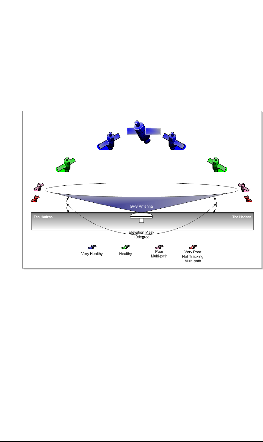
Ver.
ANNEX A. GPS Antenna Installation
© SAMSUNG Electronics Co., Ltd. page 84 of 116
2600-00FOTGGAA 6.0
A.1.1 GPS Antenna
Installation Requirements for the GPS Antenna
The GPS antenna must be installed in a location where it has the maximum amount of open sky.
The ideal position is one where there are no obstacles that interfere with the antenna within
10 degrees or more of the horizon (the Elevation Angle). This allows the GPS receiver to
select the best combination or distribution of GPS satellites which gives optimal
performance.
Figure 37. Elevation Mask and Satellites
For good signal strength, you don’t have to place the GPS antenna on a high pole or
building, which is often required for RFs and microwaves.
Any place where there are no obstacles blocking the GPS antenna from the sky and where
it is protected from the elements such as outside interference is suitable. In this case, you
can even install it on the ground.
However, you can prevent the GPS antenna from malfunctioning by installing it in a place
where it does not receive reflected satellite signals. As multi-path interference greatly
affects the accuracy of the GPS receiver, it is better to minimize reflected satellite signals
entering through the top of the GPS antenna.
Therefore, the GPS antenna installation location must meet the following three conditions.
y Location that can avoid effect of obstacle/building that interferes with reception of
GPS signal or causes multi-path
y Location that can avoid interference of RF signal that is transmitted/received at the
surrounding other RF antenna (including steel-framed structure for RF antenna) or
microwave signal
y Location as low as possible that avoid damage from lightning within coverage area of
lightning rod
Ver.
ANNEX A. GPS Antenna Installation
© SAMSUNG Electronics Co., Ltd. page 85 of 116
2600-00FOTGGAA 6.0
Considerations for Elevation Mask
Considering the elevation mask, make the GPS antenna take the signals received
at a valid elevation angle only.
Countermeasures for External Interference and Multi-path Influences
If a GPS antenna is influenced by external interference signals or multi-paths at
a certain place, it is best to re-install the antenna at another place. Anti-jamming
GPS antenna is recommended if it is not possible to change the location of the
antenna.
GPS Antenna Sharing
To ensure the GPS receiver works properly, it is recommended you install one GPS antenna
per GPS receiver. It is also recommended you use a GPS-specific splitter only if absolutely
necessary.
Installing the GPS Antenna
The signals from a GPS satellite have a very low level (-130 dBm). Because of this, the
GPS antenna to receive them should be installed in a place where it can receive signals as
directly as possible from as many satellites as possible.
Therefore, it is important to ensure there is maximum open sky (the visual field angle must
be 360 degrees, and there must be 160 degrees or more above the horizon). This means that
the antenna is mostly installed on a high place, such as a roof. If there is an obstacle within
those angles, it decreases the performance and functionality of the GPS receiver.
The GPS satellites are distributed so that eight of them can always be tracked from any one
place across the world, as long as there is no obstacle to them in that particular place.
For the GPS receiver to operate at its best, there must be always six GPS satellites with a
healthy status (i.e., there is no obstacle directly between it and the GPS antenna).
If the position hold operation has been completed, the GPS receiver can only perform its
operations stably if at least one satellite can be tracked continually.
GPS Satellite Tracking and Position Hold
The survey of an object’s position using GPS satellites is based on triangulation.
Three satellites are enough to survey the position of an object by triangulation.
However, to calculate the correct time deviation, a total of four satellites are
required.
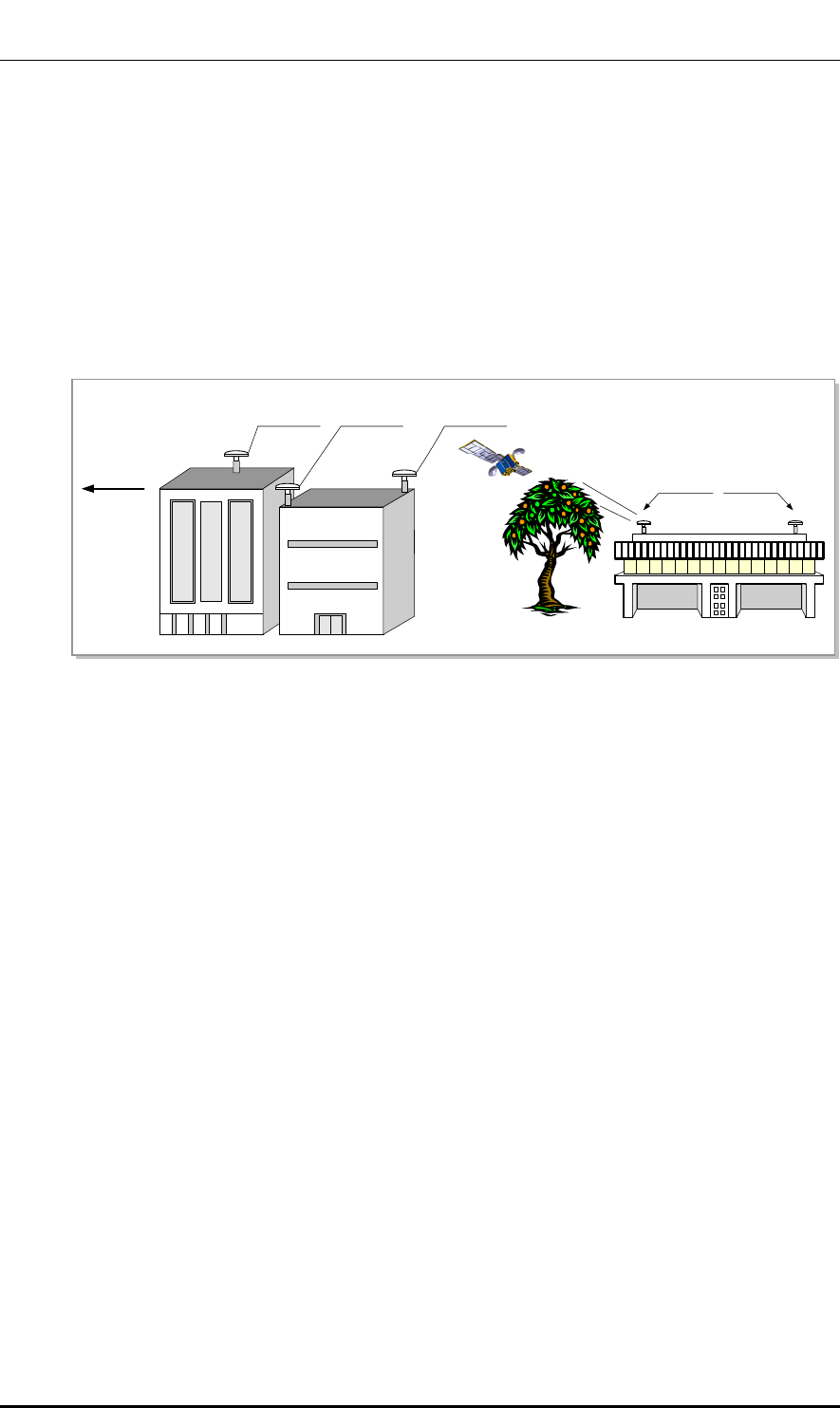
Ver.
ANNEX A. GPS Antenna Installation
© SAMSUNG Electronics Co., Ltd. page 86 of 116
2600-00FOTGGAA 6.0
Usually, the GPS antenna is installed in a high place, such as on a roof. It must be installed
away from protruding objects, such as trees or buildings. In addition, it must be positioned
away from any obstacle which covers part of the sky around the horizon of the building
where it is installed.
If it is impossible to ensure a completely open sky, you should install the GPS antenna
facing the equator providing a maximum view of the Southern sky (Northern sky in the
Southern hemisphere).
Furthermore, when installing the GPS antenna using a steel cylinder structure shared by
other RF antennas, it must be separated by more than 1 m from that steel structure.
Figure 38. GPS Antenna Installation
A.1.2 Lightening Arrestor
A lightning arrestor is required when there is a danger of lightning striking a cable or
related part. The lightning arrestor must be installed in a place where the antenna cable or
set of combined cables enters a building or station, or a place inside the building or station.
The purpose of this is to protect the people and equipment inside the building or station.
If struck directly by lightning, the lightning arrestor, antenna, or cable must be replaced.
Furthermore, you must inspect the lightening arrestor periodically, and replace the antenna
and cable periodically to ensure protection if lightning occurs frequently at the site.
The lightning arrestor must be well grounded so that it can transmit a large current quickly.
Towards
Equator
Preferred
Position
Obstructed
Position
Improved
Visibility
Obstructed
position
Better
Position

Ver.
ANNEX A. GPS Antenna Installation
© SAMSUNG Electronics Co., Ltd. page 87 of 116
2600-00FOTGGAA 6.0
A.2 Interference Signal
The GPS system is designed so that it has a strong immunity to noise and can endure
interference.
The Samsung GPS receiver provides a quality timing clock in most installations.
However, to ensure that the GPS receiver performs locking successfully and guarantees
uninterrupted timing performance, an interference-free environment is required for
frequencies near the GPS L1 frequency (1575.42 ± 1 MHz).
Interference Types
There are two types of interference which affect the GPS L1 frequency.
y Narrow band (inband) interference
When a frequency deviation (3.5 kHz), such as an FM wave, inflows in around the
GPS L1 frequency (1575.42 MHz). This is called narrow band (inband) interference.
Narrow band interference is monitored by the spectrum analyzer. But because it has a
time lag, a locking failure or a different type of alarm can occur.
y Wideband interference
When around the GPS L1 frequency (1575.42 MHz), the frequency deviation is more
than 7 kHz. This is called wide band interference.
Wideband interference includes the interference induced by the harmonics from a
communication service with a different frequency bandwidth, increased thermal noise
from communication services around the L1 band, inflow of interference due to
unauthorized communication, saturation due to oscillation of an accessory device etc.
You cannot monitor these kinds of interferences with a device such as a spectrum
analyzer. If the system has a wideband interference problem, you should consult an
expert in this area.
For other bandwidths except the GPS L1 frequency (1575.42 ± 1 MHz), a GPS Band Pass
Filter (BPF) must be included within the GPS antenna to remove the interference from the
GPS bandwidth. No outband interference must affect the GPS signals.
Avoiding Interferences
If more than one antenna for other communications, such as an antenna for a base station or
satellite communication, is installed in the surroundings, the GPS antenna must be installed
in a location to which no interference signals flow in.
If interference exists within the GPS L1 frequency bandwidths (1575.42 ± 1 MHz), you
should use a band pass filter to prevent them from affecting it.
Furthermore, if the GPS antenna is installed by a transmitter which operates with a
bandwidth similar to the GPS L1 frequency, the possibility of interference increases (in this
case, interference is caused by harmonics). If the GPS antenna has a problem due to
interference, you must move it to a different location where interference signals can be
avoided or minimized in strength.

Ver.
ANNEX A. GPS Antenna Installation
© SAMSUNG Electronics Co., Ltd. page 88 of 116
2600-00FOTGGAA 6.0
Inband Noise
Inband noise includes narrow band noise and wide band noise that occur in an
inband width. (L1, 1575.42 ± 1 MHz)
- Narrow band noise in an inband width: If it is higher than 108 dBm it can affect
the operation of the GPS receiver.
- Wideband noise in an inband width: It may not be detected by a measuring
instrument and impair the sensitivity of the GPS receiver, and thus affect its
operation.
If there is an outband interference problem, you can reduce the effects of interference on
the GPS receiver by applying one or more L1 GPS band pass filters.
The filter should be installed at the following locations:
y The input connector of the Samsung GPS receiver
y Behind the antenna or the front end of a line amplifier
The filters above are used to reject jamming tones for outband signals. If interferences
actually occur in the inband signals, they will result in serious consequences.
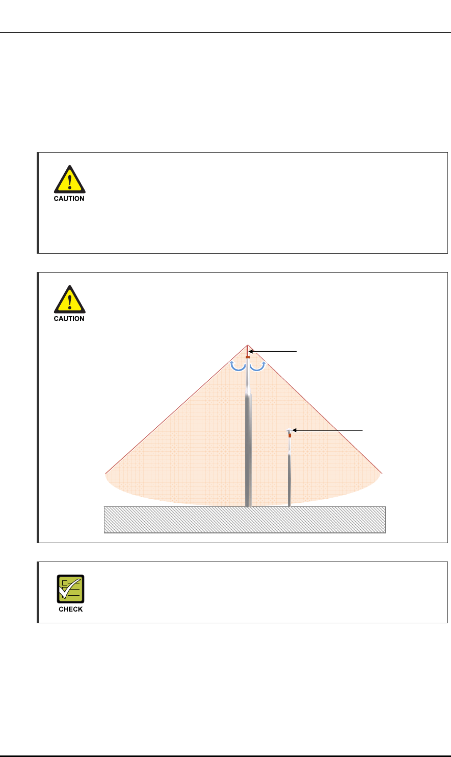
Ver.
ANNEX A. GPS Antenna Installation
© SAMSUNG Electronics Co., Ltd. page 89 of 116
2600-00FOTGGAA 6.0
A.3 GPS Antenna Installation
The GPS antenna can be fixed to a wall, floor, tower, pole, etc.
Ensure you are safe when fixing an anchor bolt to a wall and treat the anchor bolt fixing
area with a silicon or waterproof finishing material.
Installing the Concrete Block
A concrete block should be installed that satisfies the specification regarding size
and strength. When installing the concrete block, and before forming the
concrete, steel reinforcement bars should be arranged in a mesh layout at
3.93 in. (100 mm) intervals before forming the concrete. (Either an anchor bolt
assembly or a concrete anchor can be used.)
Installing the Antenna
When you install the antenna, antenna must be within the protective angle
(left/right side 45° each from the central axis) to prevent the antenna from
lightning damage.
Distance between the Antennas
When installing antenna, 3.28~4.92 ft (1~1.5 m) distance must be secured
between the antennas for preventing interference.
Lightning Rod
45° 45°
GPS Antenna
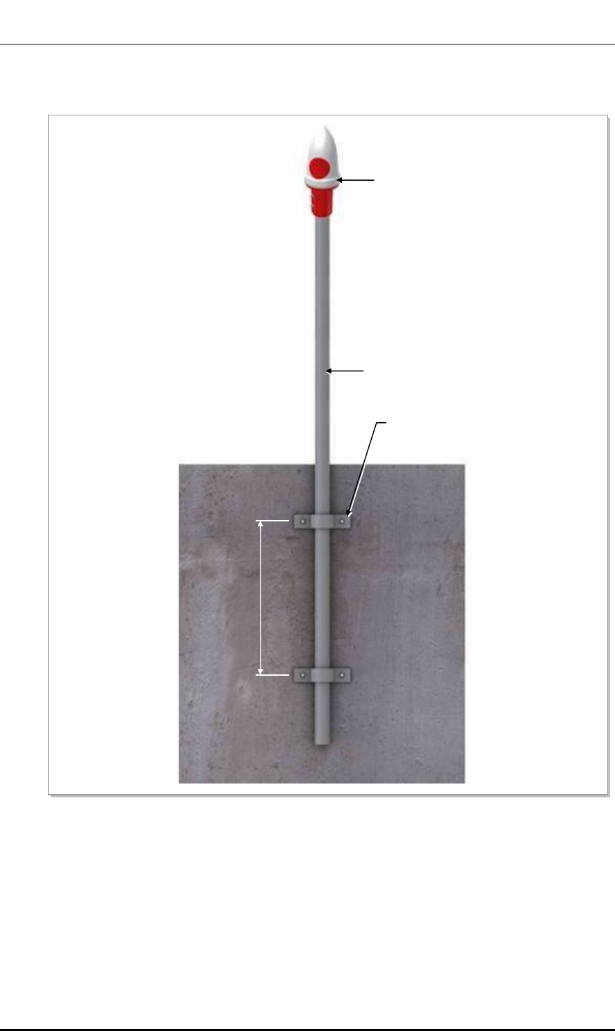
Ver.
ANNEX A. GPS Antenna Installation
© SAMSUNG Electronics Co., Ltd. page 90 of 116
2600-00FOTGGAA 6.0
Wall
Figure 39. GPS Antennal Installation (Wall)
GPS Antenna Wall Fixing Pipe
[Ф 1~1.46 in.(25~37 mm)]
GPS Antenna
GPS Antenna
Wall Fixing Clamp Assembly
≒ Min. 19.68 in.(500 mm )
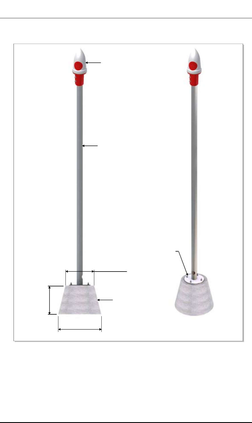
Ver.
ANNEX A. GPS Antenna Installation
© SAMSUNG Electronics Co., Ltd. page 91 of 116
2600-00FOTGGAA 6.0
Floor
Figure 40. GPS Antennal Installation (Floor)
GPS Antenna Floor Fixing Pipe
[Ф 1~1.46 in.(25~37 mm)]
GPS Antenna
M10 Anchor Bolt Assembl
y
≒ Min. 19.69 in.(500 mm)
Concrete Block
≒ Min. 15.74 in.(400 mm)
≒ Min. 9.84 in.(250 mm)
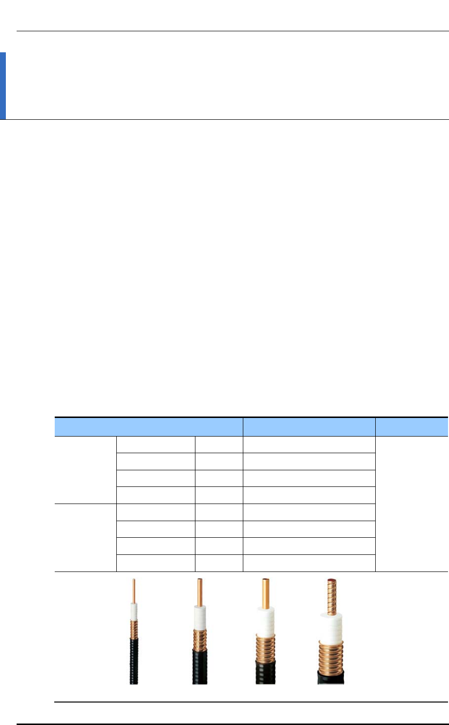
Ver.
ANNEX B. Installing Feeder Cable
© SAMSUNG Electronics Co., Ltd. page 92 of 116
2600-00FOTGGAA 6.0
ANNEX B. Installing Feeder Cable
B.1 Cautions When Installing Feeder Cable
When installing the feeder cable (GPS/RF cable), the following cautions shall be
considered:
y Put a plate to work not to make damage for the surface of the feeder cable.
If there is external damage of the feeder cable, cut the damaged part and work wiring.
y After connecting the antenna to the feeder cable, finish the connection part of the
contracted pipe using the contracted tube.
y Attach the cognitive tapes to the both ends of the feeder cable, which makes it easy to
recognize.
y When connecting cabinet, antenna and lightening arrestor, etc. to the feeder cable,
connect strongly to prevent from generating reflected wave.
y The curvature radius should be maximized, keep the minimum curvature radius.
Table 34. Curvature Radius of Feeder Cable for Outdoor
Specification Allowed Radius of Curvature Remark
LS Feeder
Line
HFC-12D 1/2 in. 4.02 in. (125 mm) Outdoor
HFC-22D 7/8 in. 9.84 in. (250 mm)
HFC-33D 1-1/4 in.
14.96 in. (380 mm)
HFC-42D 1-5/8 in.
20.08 in. (510 mm)
RFS Feeder
Line
LCF12-50 1/2 in. 4.92 in. (125 mm)
LCF78-50 7/8 in. 9.84 in. (250 mm)
LCFS114-50 1-1/4 in. 14.96 in. (380 mm)
LCF158-50 1-5/8 in. 19.69 in. (500 mm)
1/2 in. 7/8 in. 1-1/4 in. 1-5/8 in.
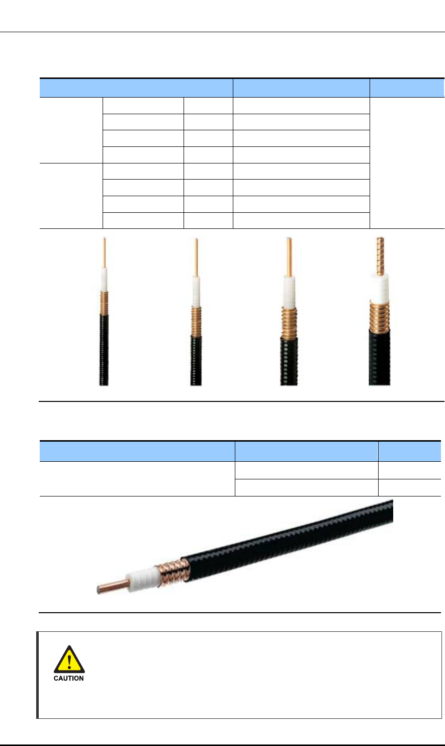
Ver.
ANNEX B. Installing Feeder Cable
© SAMSUNG Electronics Co., Ltd. page 93 of 116
2600-00FOTGGAA 6.0
Table 35. Curvature Radius of Feeder Cable for Indoor (Based on LS Feeder Line)
Specification Allowed Radius of Curvature Remark
LS Feeder
Line
HFSC 6D 1/4 in. 0.98 in. (25 mm) Indoor
HFSC 10D 3/8 in. 0.98 in. (25 mm)
HFSC 12D 1/2 in. 1.26 in. (32 mm)
HFSC 22D 7/8 in. 4.92 in. (125 mm)
RFS Feeder
Line
SCF14-50 1/4 in. 0.98 in. (25 mm)
SCF38-50 3/8 in. 0.98 in. (25 mm)
SCF12-50 1/2 in. 1.26 in. (32 mm)
UCF78-50 7/8 in. 4.92 in. (125 mm)
Table 36. Curvature Radius of LDF4-50A
Specification Allowed Radius of Curvature Remark
LDF4-50A 2 inch (50.8 mm) Installation
5 inch (127.0 mm) Repeated
Radius of Curvature of Feeder Line
When installing a feeder line, the radius of curvature of the sections where cables
bent should be larger than the allowed radius of curvature. If the radius of
curvature for the feeder line installation is less than the allowed radius of
curvature, it may affect the performance of the system.
1/4 in. 3/8 in. 1/2 in. 7/8 in.
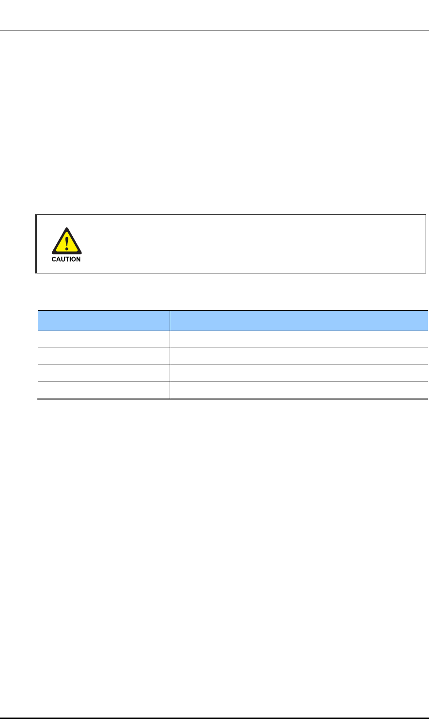
Ver.
ANNEX B. Installing Feeder Cable
© SAMSUNG Electronics Co., Ltd. page 94 of 116
2600-00FOTGGAA 6.0
y Ensure that the feeder cable does not interfere with steel towers, ladders and in the
areas chiefly used by people.
y Connect the connector to the antenna in a straight line and after connecting, do not
apply excessive force.
y Use the vinyl tape for electricity and heat shrink tube for the external exposed part of
the connector not to avoid leak water.
y Wind the self-bonding rubber tape overlapping (keep a distance as the half size of
rubber tape) to the connector connection part and wind the vinyl tape for electricity to
the 2 times or more and then cover with the jelly type heat shrink tube.
Connection of Feeder Cable Connector
Connecting the feeder cable connector is critical process, so the qualified workers
who finished the related education should perform.
Table 37. Connector Connection Torque Value
Connector Torque Value
SMA connector 0.18 lbf·ft (2.5 kgf·cm)
TNC connector 0.65 lbf·ft (9 kgf·cm)
N-type connector 1.45 lbf·ft (20 kgf·cm)
Din-type connector 14.46 lbf·ft (200 kgf·cm)
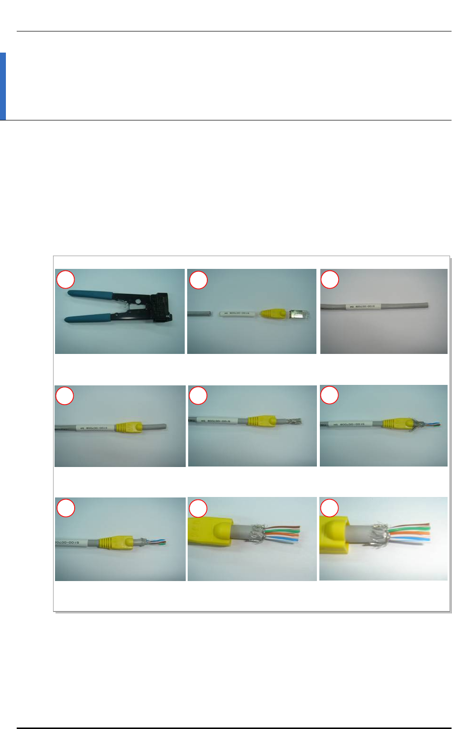
Ver.
ANNEX C. Connector Assembly
© SAMSUNG Electronics Co., Ltd. page 95 of 116
2600-00FOTGGAA 6.0
ANNEX C. Connector Assembly
C.1 RJ-45 (Shield Type)
Procedure that assembles the RJ-45 (shield type) connector is as follows:
Figure 41. Assembling the RJ-45 Connector (Shield Type) (1)
1), 2) Prepare work tools and materials.
4) Pass the cable through the
RJ-45 cap.
5) Remove the coating 17 mm
from the end.
6) Push the shield backward,
and cut the aluminum shield.
7) Cut the shield leaving a 5 mm
of it.
8) Arrange the cable in reference
to the pin map.
9) Cut the cable to make it
12 mm long.
3) Pass the cable through the
marking tube.
1 2 3
4 56
7 89
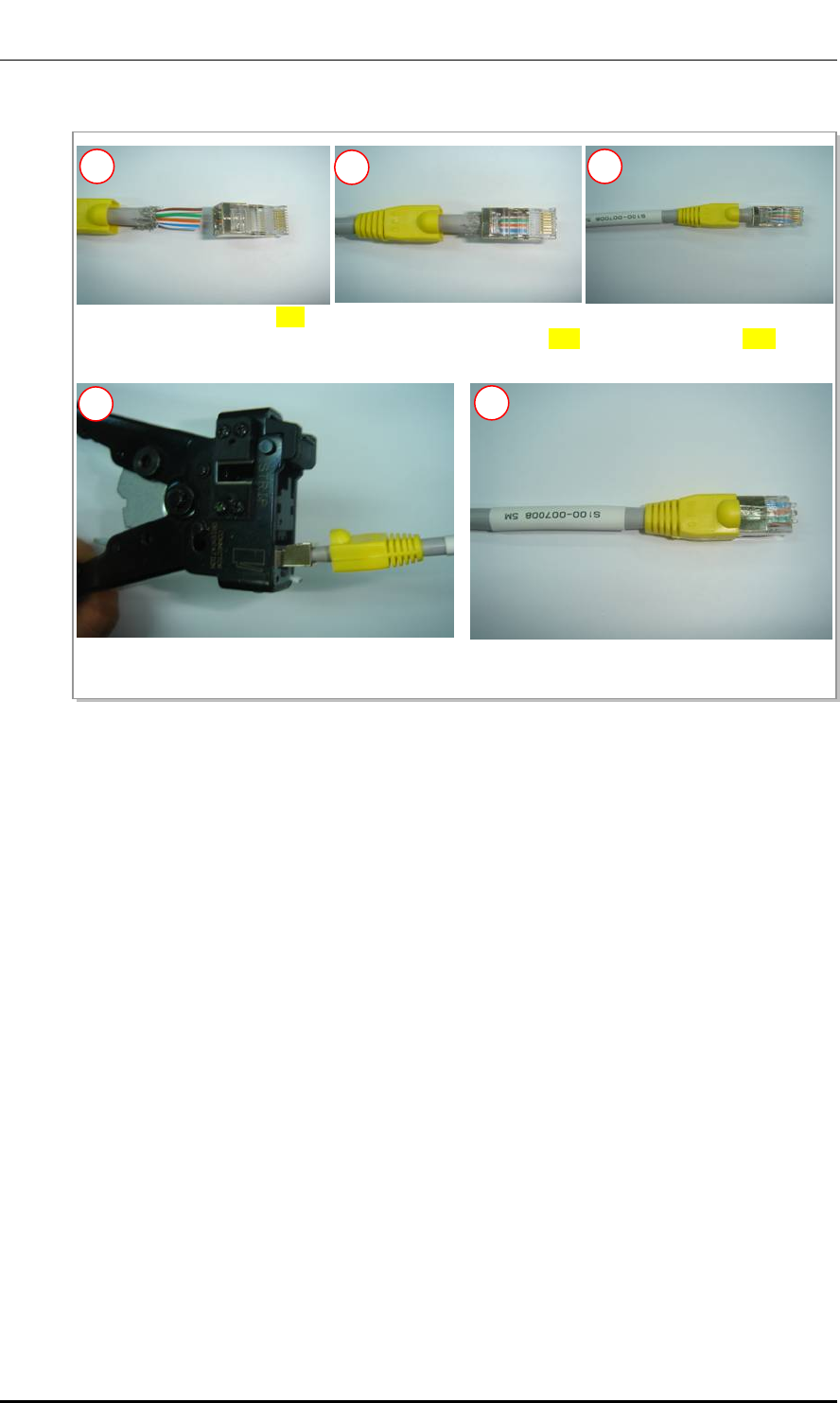
Ver.
ANNEX C. Connector Assembly
© SAMSUNG Electronics Co., Ltd. page 96 of 116
2600-00FOTGGAA 6.0
Figure 42. Assembling the RJ-45 Connector (Shield Type) (2)
10) Insert the RJ-45 modular plug. 11) Make sure that the shield does
not get in the RJ-45 modular plug.
12) Insert the cable completely into
the RJ-45 modular plug.
13) Compress the jack using the tool. 14) Compress the marking tube to finish the assembly.
10 11 12
13 14
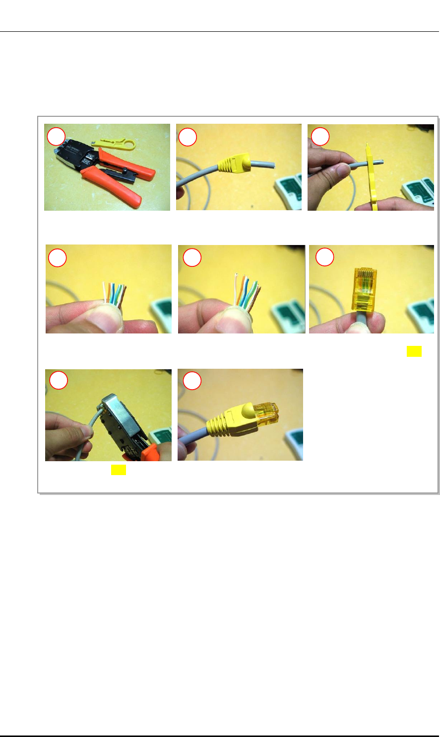
Ver.
ANNEX C. Connector Assembly
© SAMSUNG Electronics Co., Ltd. page 97 of 116
2600-00FOTGGAA 6.0
C.2 RJ-45 (Normal Type)
Procedure that assembles the RJ-45 (normal type) connector is as follows:
Figure 43. Assembling the RJ-45 Connector (Normal Type)
1) Prepare work tools and
materials.
2) Insert the RJ-45 cap to the
cable.
3) Remove the coating 17 mm
from the end.
4) Arrange the cable in reference
to the pin map.
5) Cut the cable to make it 12 mm
long.
1 23
4 56
7 8
7) Compress the plug using the
tool.
6) Insert the cable completely
into the RJ-45 modular plug.
8) Push the RJ-45 cap to the
connector.
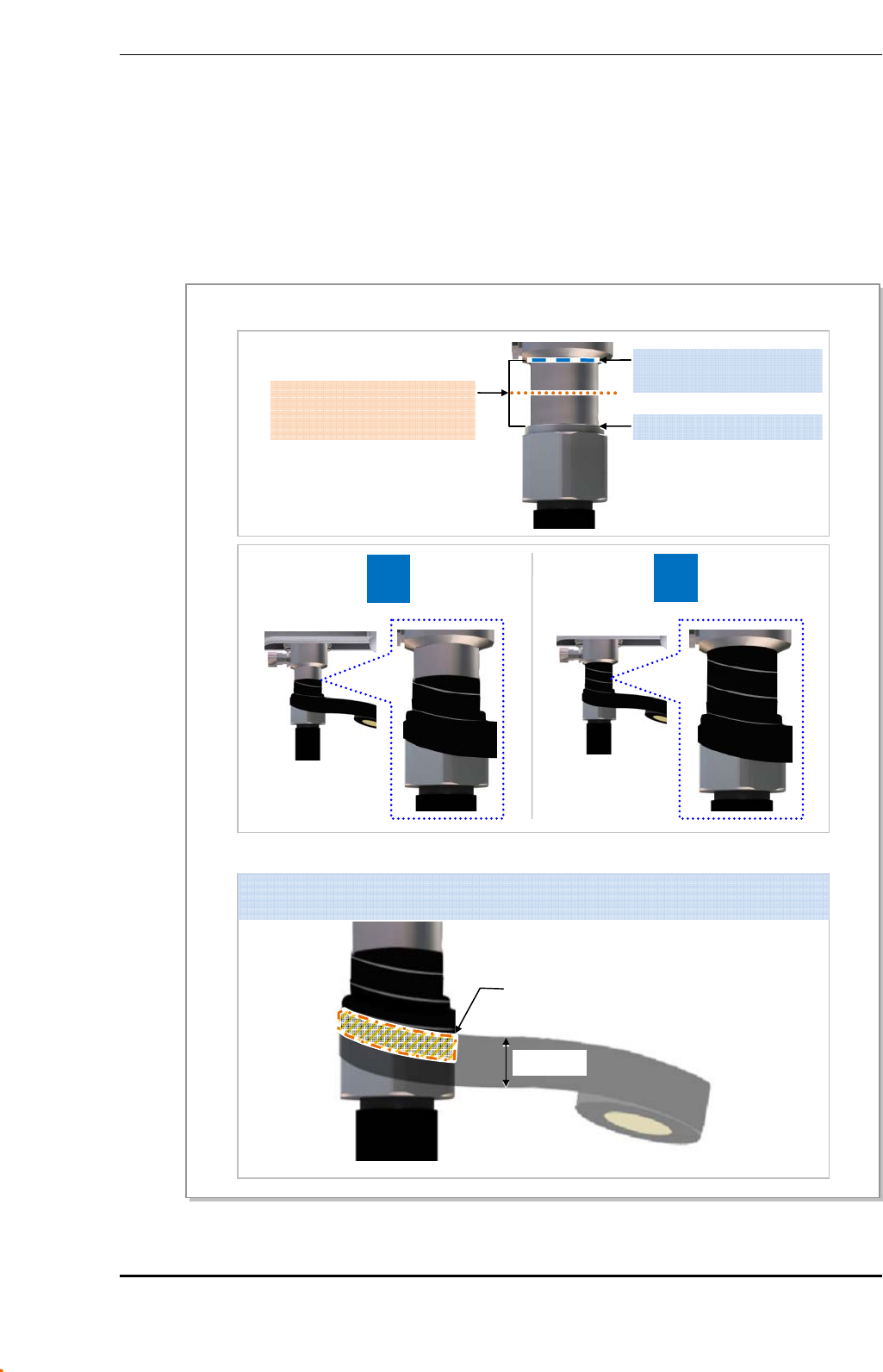
Ver.
ANNEX C. Connector Assembly
© SAMSUNG Electronics Co., Ltd. page 98 of 116
2600-00FOTGGAA 6.0
C.3 Finishing the Connector Connection Part by
Tape
Check Items for Finishing the Connector Connection Part
Check following items before finishing the connector connection part by tape.
Figure 44. Check Items for Finishing the Connector Connection Part
* Wrapping only the metal part of connector connection using insulation tape
X
O
* Wrapping the tape with overlapping
Starting and Ending points of
Insulation Tape
[Mid-point between (1) and (2)]
Wrap the tape with the half of the tape width is overlapped.
(For both insulation tape and butyl tape)
Tape Width
Overlap area of tape
(1) Starting and Ending points
of Butyl tape
(2) Top side of Connector Nut
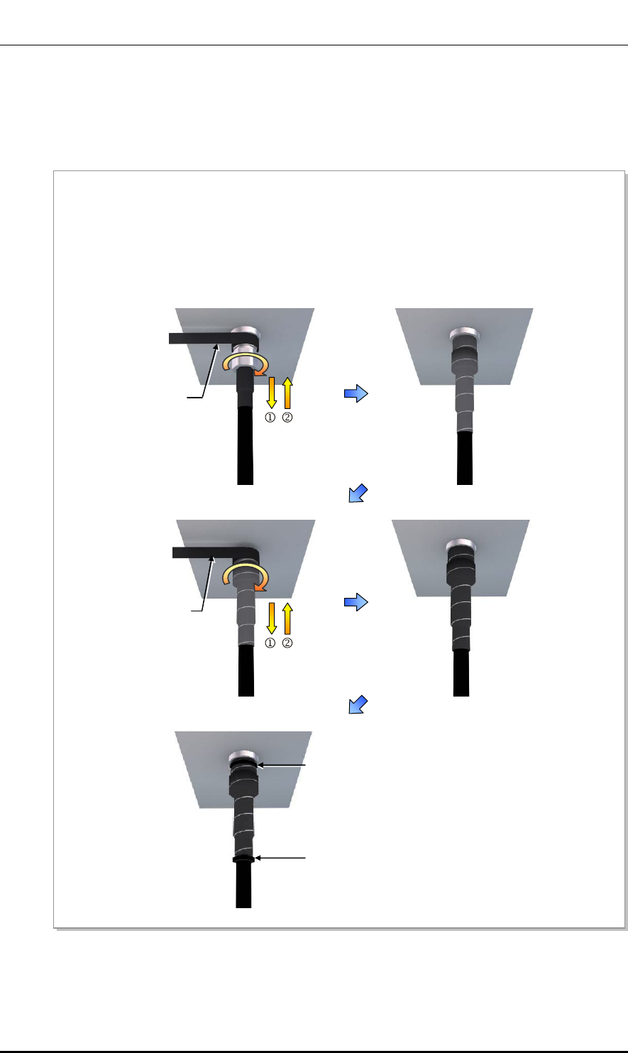
Ver.
ANNEX C. Connector Assembly
© SAMSUNG Electronics Co., Ltd. page 99 of 116
2600-00FOTGGAA 6.0
Finishing the Connector Connection Part by Tape
Finishing the connector connection part by tape (insulation tape, rubber tape, etc.) in the
outdoor environment is as follows:
Figure 45. Finishing the Connector Connection Part by Tape
Cable Tie
Rubber Ta
p
e
Insulation Ta
p
e
1) Overlap the exposed part of the connector connection part using rubber tape (Keep a distance as the
half size of rubber tape) and press it with your hands lightly to make rubber tape adhere well.
2) Wrap the part where the rubber tape is attached using insulation tape two times or more. When cutting
off the tape, cut it off neatly using a cutting device such as scissors or a knife.
3) Bind the end part of the insulation tape using cable tie to prevent slips.
Cable Tie
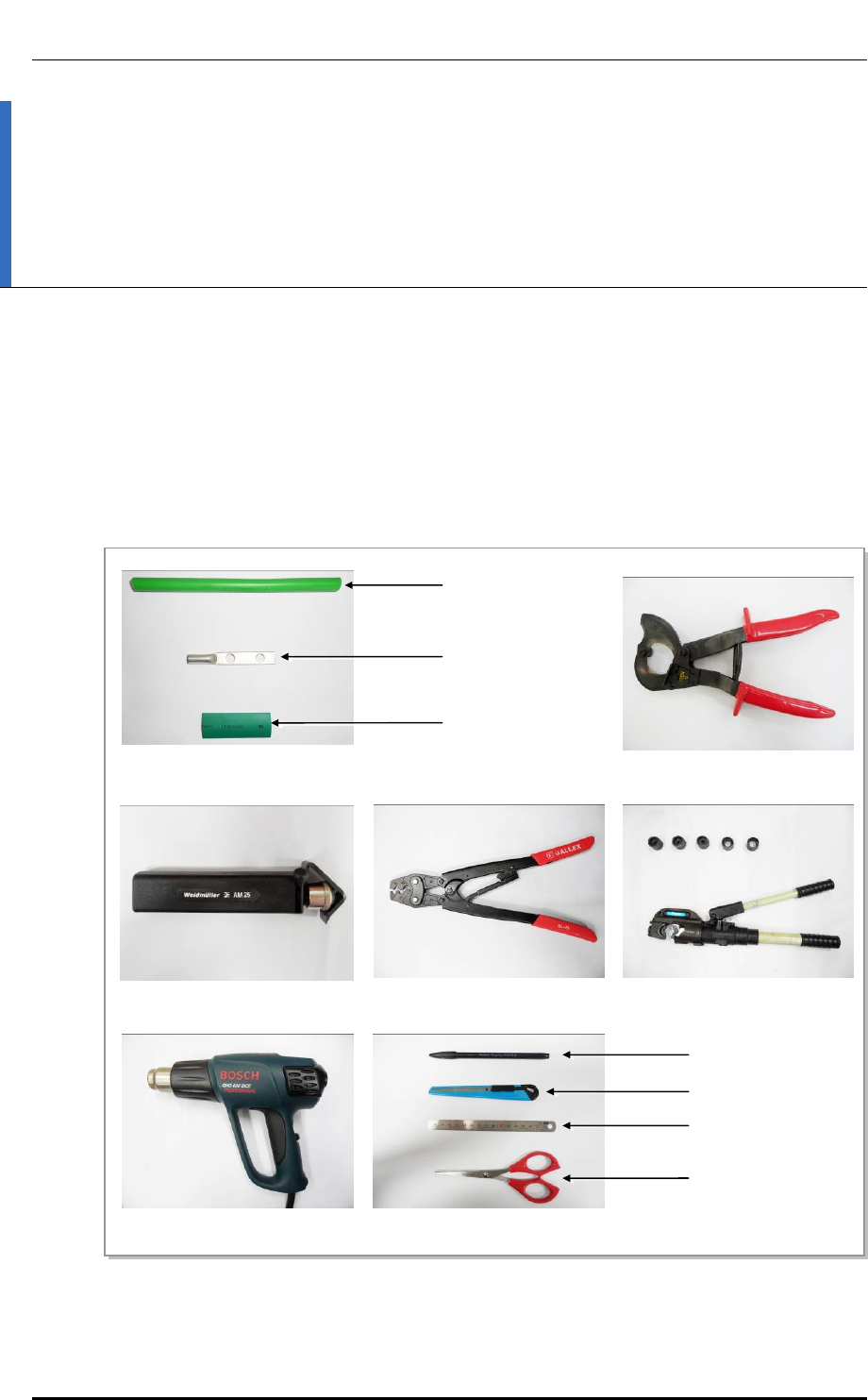
Ver.
ANNEX D. Pressure Terminal Assembly
© SAMSUNG Electronics Co., Ltd. page 100 of 116
2600-00FOTGGAA 6.0
ANNEX D. Pressure Terminal
Assembly
D.1 Preparations
The followings must be prepared to connect a pressure terminal to a cable.
Figure 46. Preparations
[Cable Cutter]
[Wire Stripper] [Handheld Compressor] [Hydraulic Press]
[Heating Gun]
[Marking Pen]
[Cutter Blade]
[Steel Ruler]
[Scissors]
[Cable]
[Pressure Terminal]
[Heat Shrink Tube]
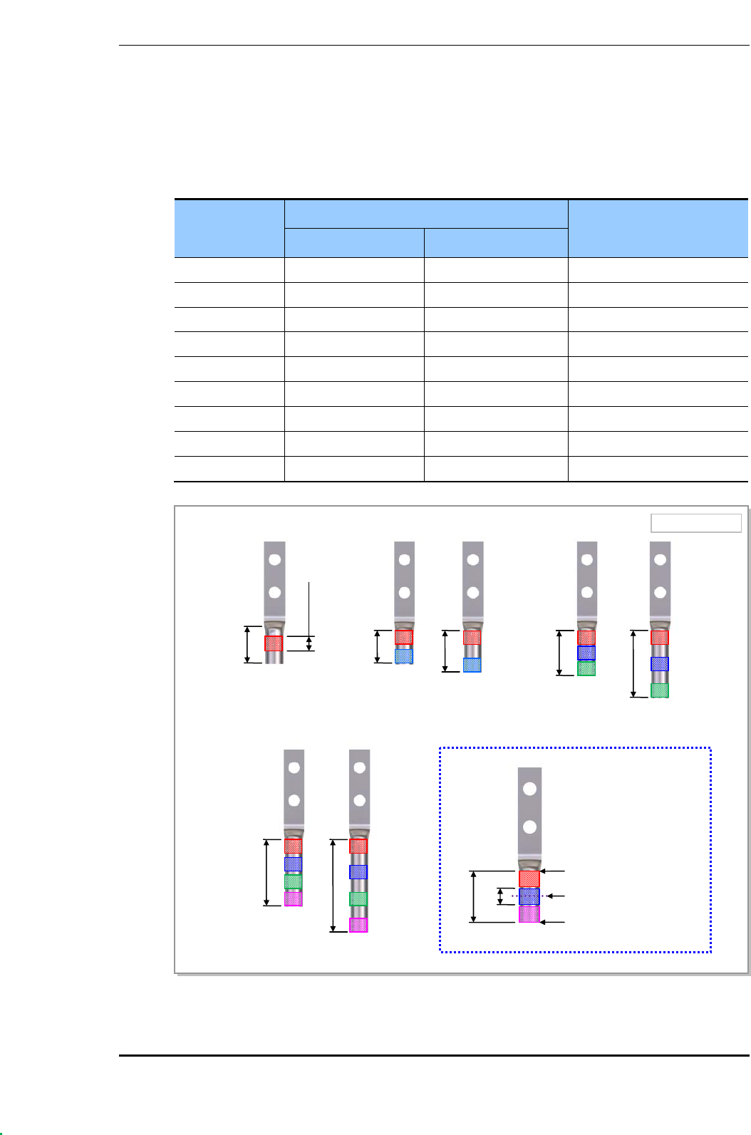
Ver.
ANNEX D. Pressure Terminal Assembly
© SAMSUNG Electronics Co., Ltd. page 101 of 116
2600-00FOTGGAA 6.0
D.2 Pressure Reference Table
The pressure reference table used to assemble a pressure terminal to a cable is shown below.
Table 38. Pressure Reference Table for Pressure Terminal
Category Copper tube length of a pressure terminal Number of pressure points
mm In.
Hand 11 mm or less 0.43 in. 1
Hand 12~15 mm 0.47~0.59 in. 2
Hand 16~23 mm 0.63~0.91 in. 3
Hand 24~32 mm 0.94~1.26 in. 4
Hand 33 mm or more 1.3 in. or more 5
Hydraulic 30 mm or less 1.18 in. or less 2
Hydraulic 31~47 mm 1.22~1.85 in. 3
Hydraulic 48~63 mm 1.89~2.48 in. 4
Hydraulic 64 mm or more 2.52 in. or more 5
Figure 47. Pressure Reference Drawing (Handheld Compressor)
[1-spot] [2-spot] [3-spot]
[4-spot]
Unit: in. (mm)
0.43 (11)
0.18 (4.5)
0.47 (12)
0.59 (15)
0.63 (16)
0.91 (23)
0.94 in. (24)
1.26 (32)
0.63 (16)
0.18 (4.5)
Copper Tube Starting
Middle of Copper Tube
A
rbitrary Fixing
Reference Points
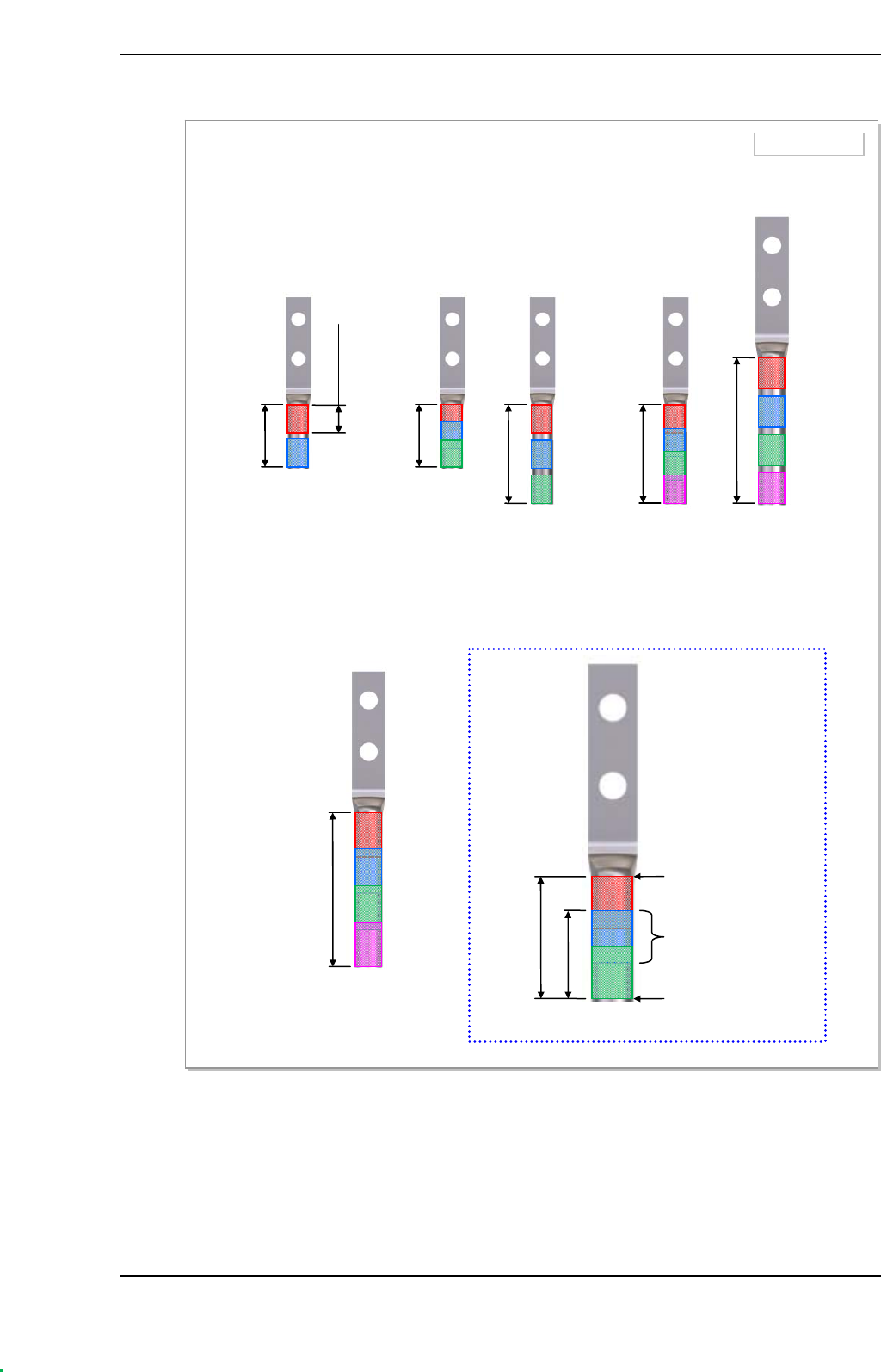
Ver.
ANNEX D. Pressure Terminal Assembly
© SAMSUNG Electronics Co., Ltd. page 102 of 116
2600-00FOTGGAA 6.0
Figure 48. Pressure Reference Drawing (Hydraulic Press)
Unit: in. (mm)
[2-spot] [3-spot] [4-spot]
1.18 (30)
[4-spot]
Copper Tube
Starting
Duplicate Pressure
A
rbitrary Fixing
Reference Points
0.53 (13.5)
1.22 (31)
0.53 (13.5)
1.22 (31)
1.85 (47)
1.89 (48)
2.48 (63)
2.52 (64)

Ver.
ANNEX D. Pressure Terminal Assembly
© SAMSUNG Electronics Co., Ltd. page 103 of 116
2600-00FOTGGAA 6.0
Table 39. Compressor Specifications per Cable Thickness
Cable Size
(mm2)
Press Size
Small Handheld Press Large Handheld Press
(AK-38, 100)
Hydraulic Press
(IZUMI Hexagonal Dies)
2.5 2 X X
4 2 X X
6 5.5 X X
10 8 8 X
16 14 14 16
25 22 22 25
35 38 38 35
50 X 60 50
70 X 80 70
95 X 100 95~300
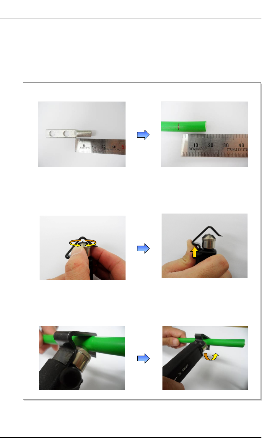
Ver.
ANNEX D. Pressure Terminal Assembly
© SAMSUNG Electronics Co., Ltd. page 104 of 116
2600-00FOTGGAA 6.0
D.3 Assembling Pressure Terminal
The procedures for assembling a pressure terminal to a cable are as follows:
Strip the Cable Sheath
Figure 49. Stripping Cable Sheath (1)
4) Put a cable into a clamp, locate a blade on a marking position, and push it into the sheath.
5) Align the stripper to be perpendicular to the cable and rotate it more than two laps.
1) After checking the inside length of a pressure terminal, mark the cable.
2) Adjust the length of a cutter blade according to the sheath thickness of the cable.
3) Push the clamp with a thumb a ccording to the cable size to secure a space for the cable.
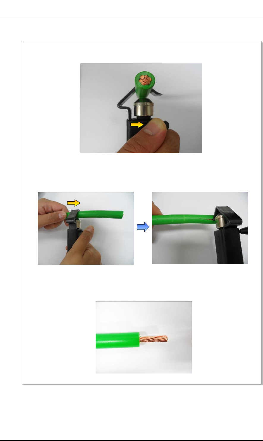
Ver.
ANNEX D. Pressure Terminal Assembly
© SAMSUNG Electronics Co., Ltd. page 105 of 116
2600-00FOTGGAA 6.0
Figure 50. Stripping Cable Sheath (2)
6) Push the lever of the stripper to the right to turn its blade at 90°.
8) Remove the sheath.
7) Move the stripper up to the end of cable while maintaining the stripper to be perpendicular to the cable.
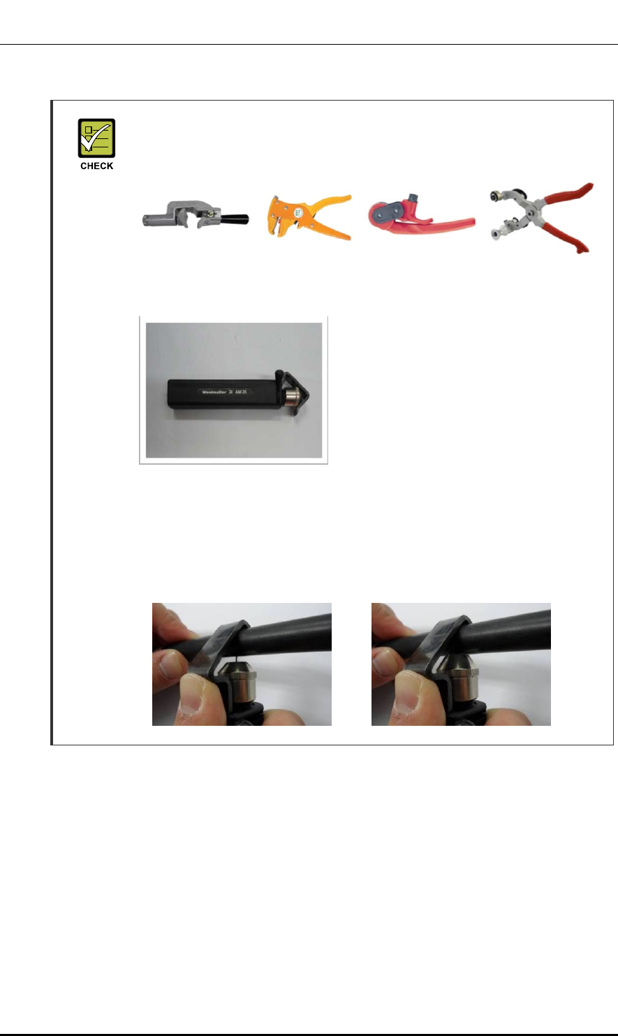
Ver.
ANNEX D. Pressure Terminal Assembly
© SAMSUNG Electronics Co., Ltd. page 106 of 116
2600-00FOTGGAA 6.0
Checking When Using A Wire Stripper
A wire stripper is used differently depending on its manufacturer or type.
Therefore, refer to the user manual enclosed with the product.
The specifications and cautions of a wire stripper described in this manual are as
follows:
Vender: Weidmuller
Model: Weidmuller-AM25
(Order No-9001080000)
Specifications: For outer diameter 6-24 mm
PVC sheath Up to 4.5 mm
sheath cutting depth
- To prevent the cutter blade of a wire stripper from touching the cable conductor,
adjust the length of cutter blade by checking the cable sheath thickness.
- Make sure that the cutter blade goes into the cable sheath completely.
- Rotate the wire stripper perpendicularly to the cable.
[X] [O]
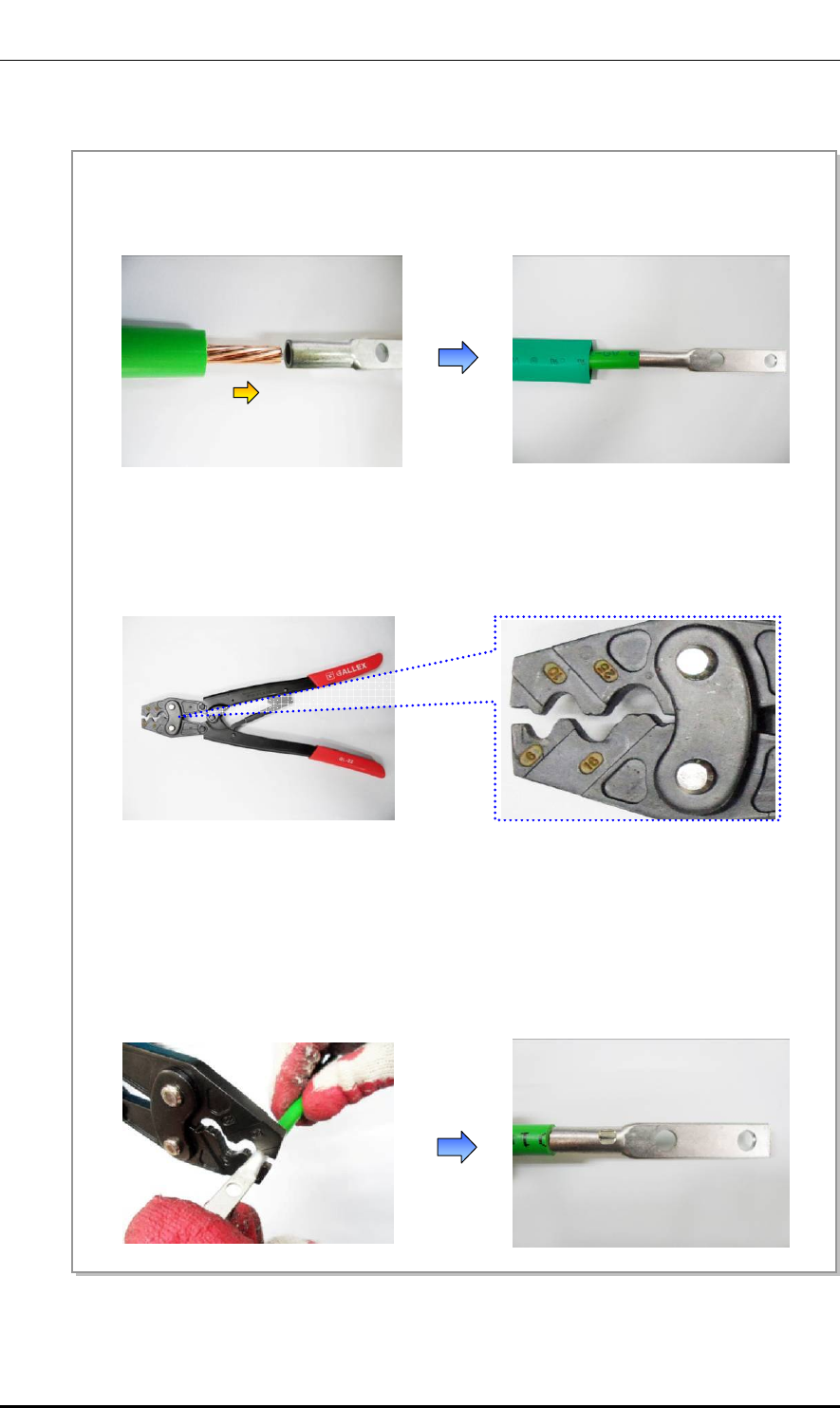
Ver.
ANNEX D. Pressure Terminal Assembly
© SAMSUNG Electronics Co., Ltd. page 107 of 116
2600-00FOTGGAA 6.0
Fixing Pressure Terminal (Handheld Compressor)
Figure 51. Fixing Pressure Terminal_Handheld Compressor (1)
1) Insert the conductor of the cable with the sheath stripped to the internal end of pressure terminal.
For a ring type pressure terminal, push it in until the conduct comes out 1 mm from the end of the
terminal.
2) From the holes of handheld compressor, select one that fits to the pressure terminal.
3) Insert the pressure terminal to the selected hole.
4) Fix the pressure terminal and cable temporarily so the position can be changed later by pressing the
compressor.
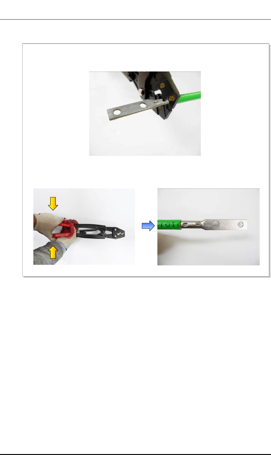
Ver.
ANNEX D. Pressure Terminal Assembly
© SAMSUNG Electronics Co., Ltd. page 108 of 116
2600-00FOTGGAA 6.0
Figure 52. Fixing Pressure Terminal_Handheld Compressor (2)
5) After complementary of the cable which is temporary fixed, align it to the hole and firmly compress the
pressure terminal to secure fix it.
6) Separate the pressure terminal from the handheld compressor. Press down the handle of compressor
until a clicking sound is heard to be unlocked.
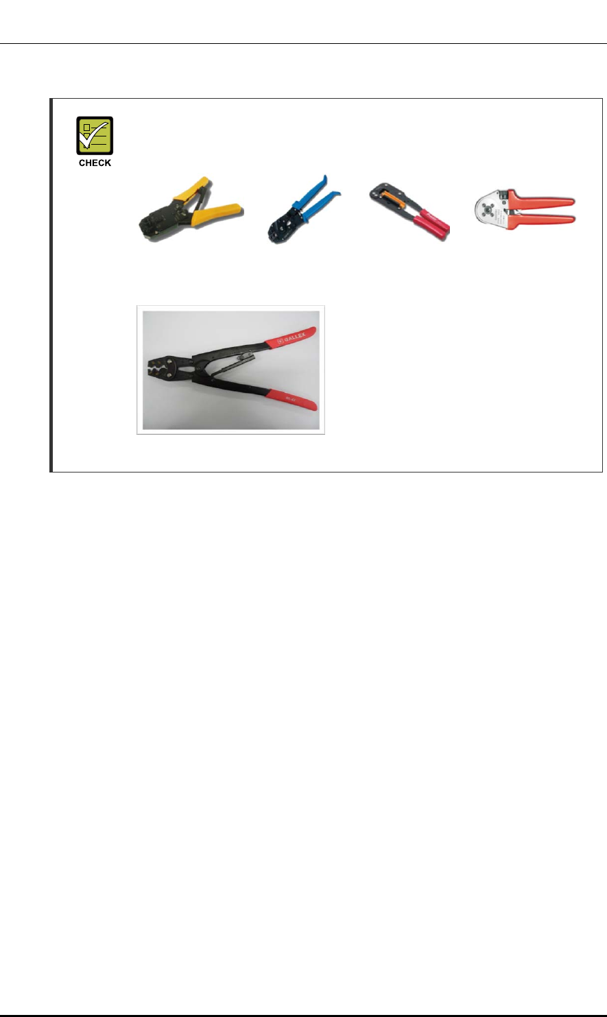
Ver.
ANNEX D. Pressure Terminal Assembly
© SAMSUNG Electronics Co., Ltd. page 109 of 116
2600-00FOTGGAA 6.0
Checking When Using A Handheld Compressor
A handheld compressor is used differently depending on its manufacturer or type.
Therefore, refer to the user manual enclosed with the product.
The specifications and cautions of a handheld compressor described in this
manual are as follows:
Vender: GALLEX
Model: GL-2045A-22
Specification: 5.5 mm2, 8 mm2, 14 mm2,
22 mm2 (JIS)
6 mm2, 10 mm2, 16 mm2,
25 mm2 (DIN)
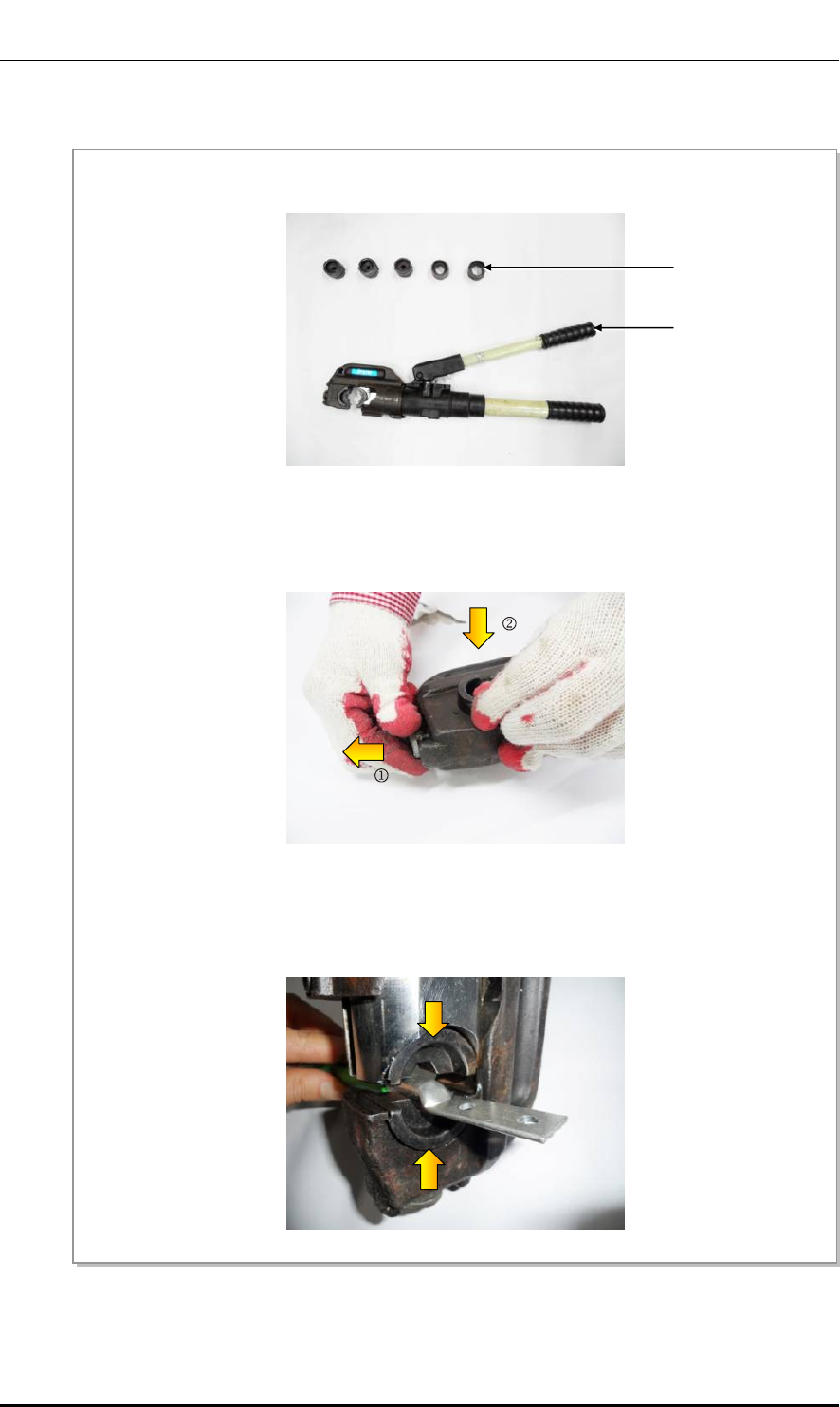
Ver.
ANNEX D. Pressure Terminal Assembly
© SAMSUNG Electronics Co., Ltd. page 110 of 116
2600-00FOTGGAA 6.0
Fixing Pressure Terminal (Hydraulic Press)
Figure 53. Fixing Pressure Terminal_Hydraulic Press (1)
1) Among the dies of the hydraulic press, select one that fits to the pressure terminal.
Dies
Hydraulic
Press
2) Assemble the dies to the pressing area of the compressor.
3) Insert the pressure terminal into the pressing area and fix it slightly by aligning it to the end of cable
sheath.
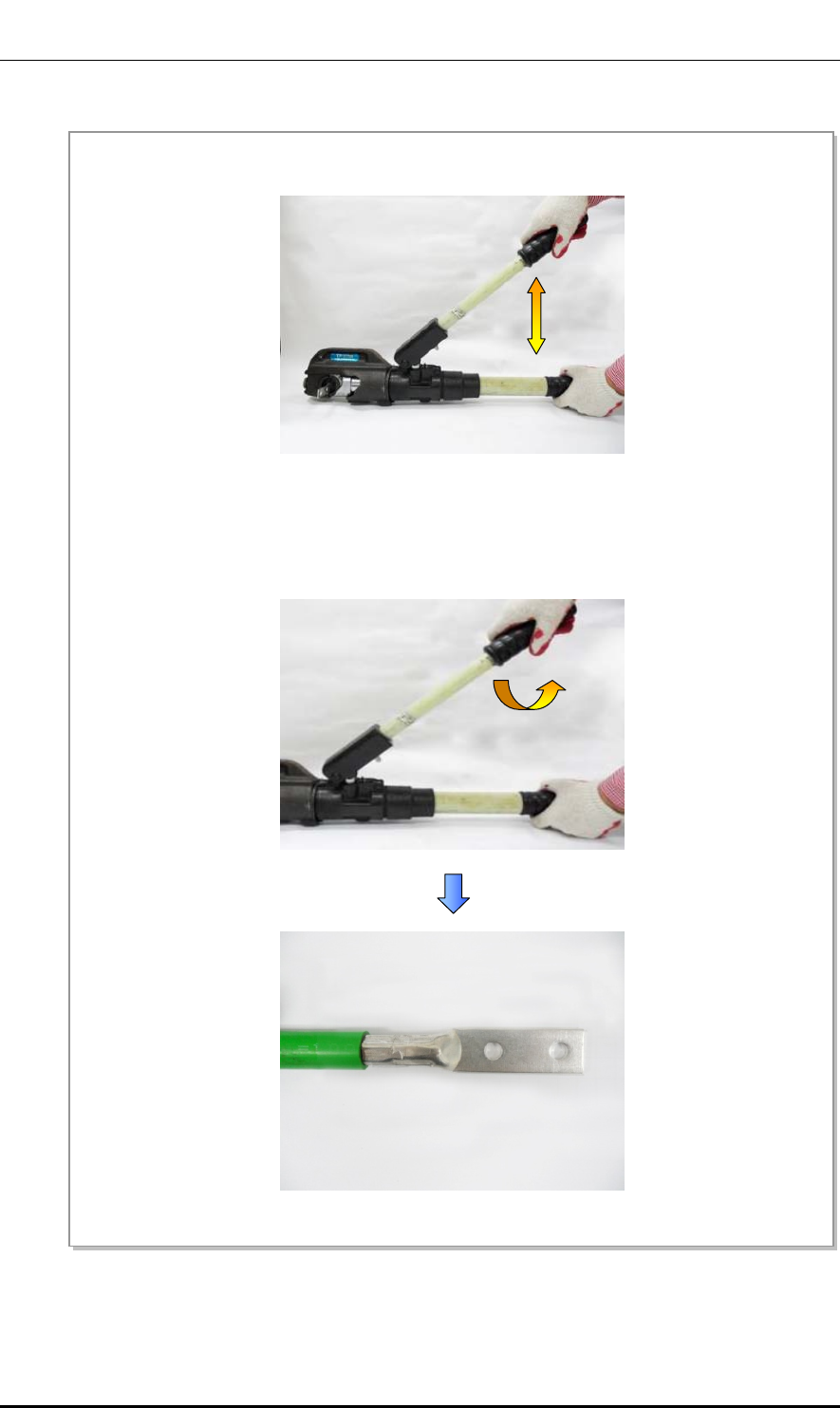
Ver.
ANNEX D. Pressure Terminal Assembly
© SAMSUNG Electronics Co., Ltd. page 111 of 116
2600-00FOTGGAA 6.0
Figure 54. Fixing Pressure Terminal_Hydraulic Press (2)
4) Move the compressor lever up and down to press the pressure terminal firmly.
5) Turn the top compressing lever clockwise and then push it down. When the pressing area of
compressor is loosened, remove the pressure terminal.
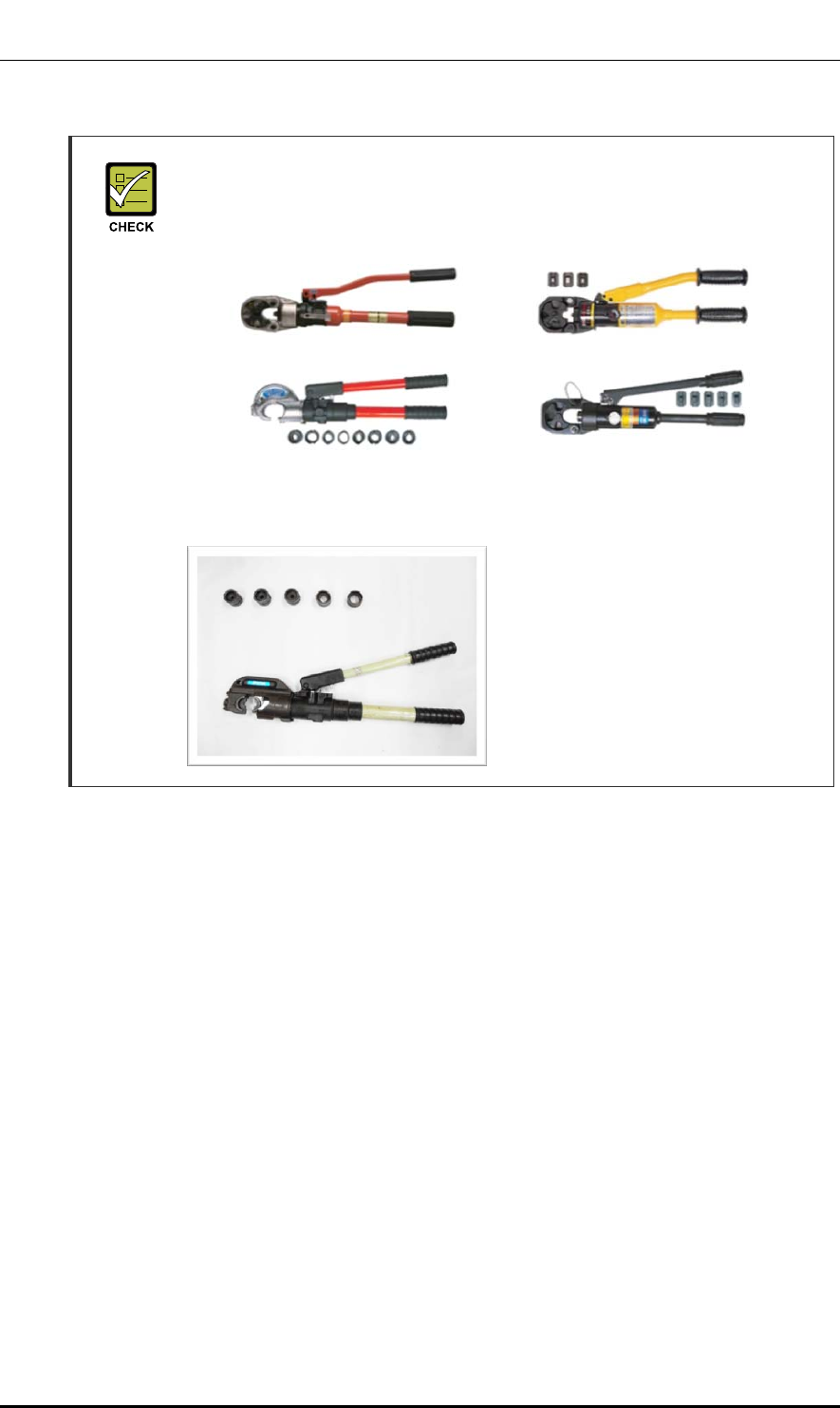
Ver.
ANNEX D. Pressure Terminal Assembly
© SAMSUNG Electronics Co., Ltd. page 112 of 116
2600-00FOTGGAA 6.0
Checking When Using a Hydraulic Press
A hydraulic press is used differently depending on its manufacturer or type.
Therefore, refer to the user manual enclosed with the product.
The specifications and cautions of a hydraulic press described in this manual are
as follows:
Vender: IZUMI
Model: IZUMI-EP-510B
Specification: Circular 32~160 (SQ)
Hex 14~325 (SQ)
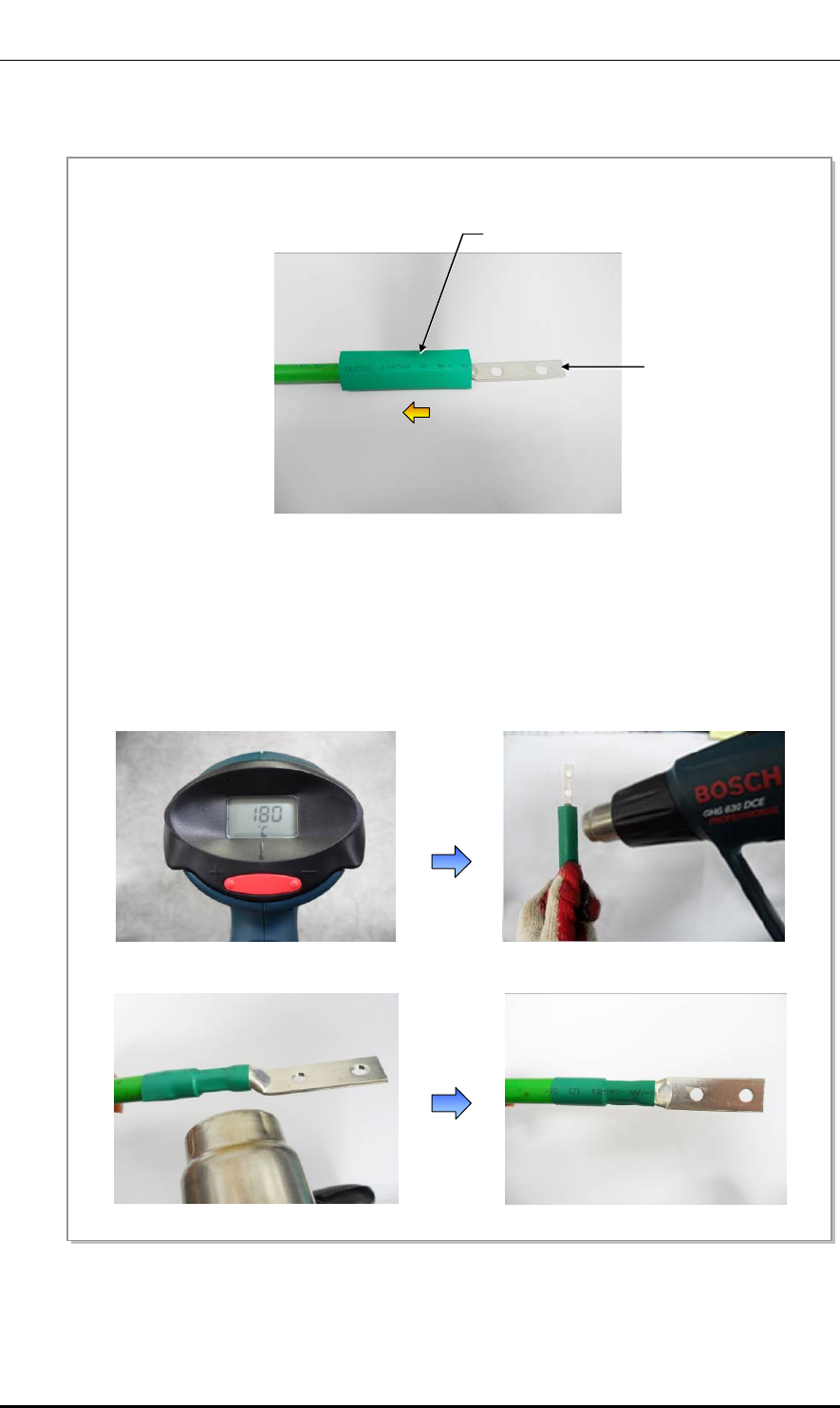
Ver.
ANNEX D. Pressure Terminal Assembly
© SAMSUNG Electronics Co., Ltd. page 113 of 116
2600-00FOTGGAA 6.0
Assembling Heat Shrink Tube
Figure 55. Assembling Heat Shrink Tube
2) Set the temperature of the heat gun to 180-200°C.
3) Locate a heat shrink tube to cover the entire copper tube of the pressure terminal.
4) Rotate a heat gun 360° to apply heat evenly to shrink the tube.
(Because the pressure terminal and the cable is hot due to the heat of a heating gun, be careful not to
have a burn.)
1) After assembling a pressure terminal, move the heat shrink tube, inserted to the cable, to the end of
pressure terminal copper tube.
Heat Shrink Tube
Pressure Terminal
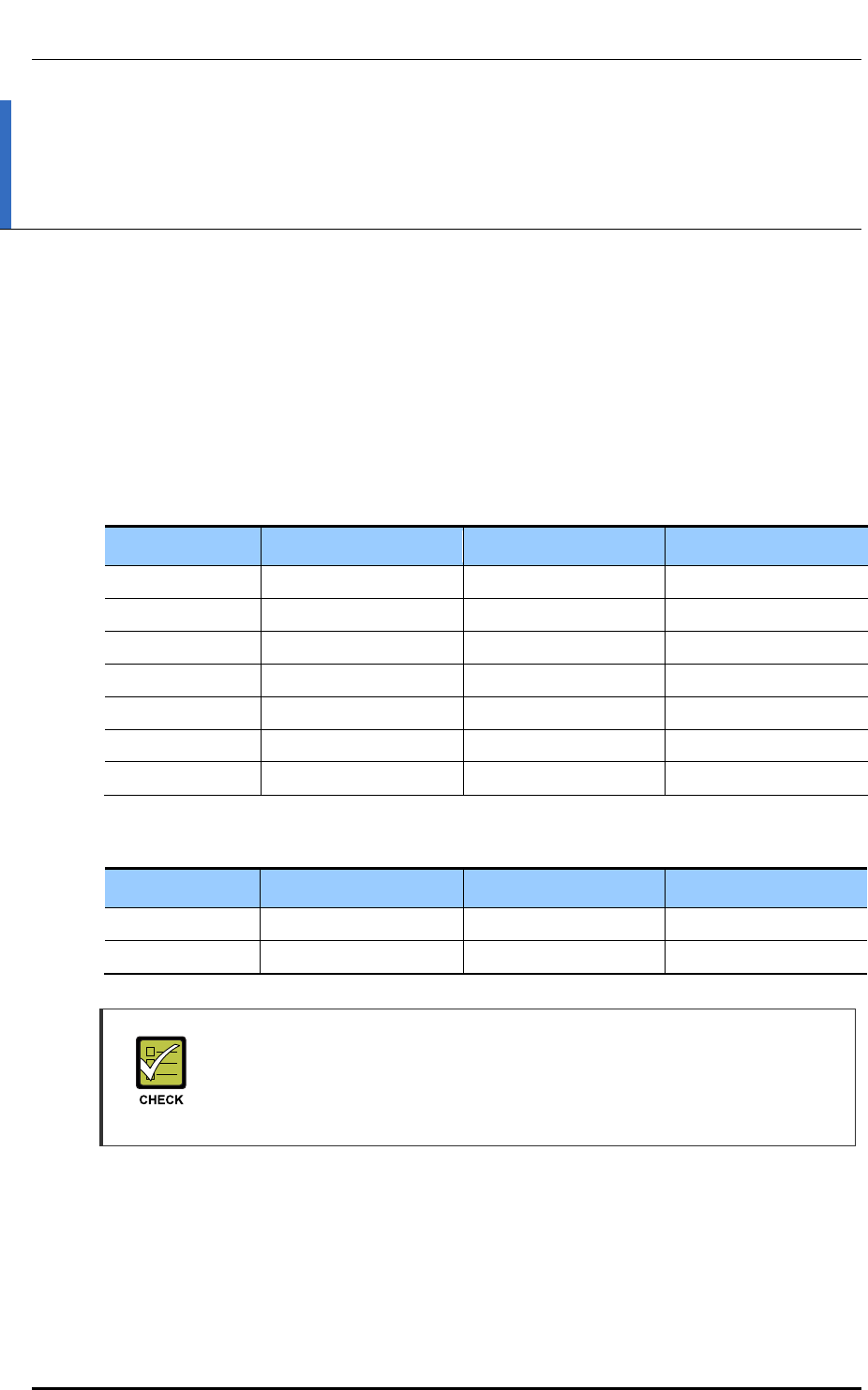
Ver.
ANNEX E. Standard Torque
© SAMSUNG Electronics Co., Ltd. page 114 of 116
2600-00FOTGGAA 6.0
ANNEX E. Standard Torque
When you tighten the bolt, refer to the standard torque value below to prevent the
equipment and bolt from damage and secure by tightening. When the torque value for each
connection part is defined already, refer to the defined value.
Table 40. Standard Torque Value for Tightening Bolts
Bolt Spec. Torque Value (kgf·cm) Torque Value (N.m) Torque Value (lbf·ft)
M3 4.08~6.12 0.40~0.60 0.29~0.44
M4 9.52~14.28 0.93~1.40 0.69~1.03
M5 20.0~30.0 1.96~2.94 1.45~2.17
M6 33.28~49.92 3.26~4.90 2.41~3.61
M8 82.4~123.6 8.08~12.12 5.96~8.94
M10 166.4~249.6 16.32~24.48 12.03~18.05
M12 292.0~438.0 28.64~42.65 21.11~31.67
Table 41. Brass Bolts Torque Value
Bolt Spec. Torque Value (kgf·cm) Torque Value (N.m) Torque Value (lbf·ft)
M6 29.98 ± 10 % 2.94 ± 10 % 2.17 ± 10 %
M8 64.26 ± 10 % 6.3 ± 10 % 4.16 ± 10 %
Checking Standard Torque Value
Torque value can be different, defending on the material, characteristic and
specification of the equipment and fastener. Make sure to check the proper torque
value for each specification of the equipment and fastener.

Ver.
ABBREVIATION
© SAMSUNG Electronics Co., Ltd. page 115 of 116
2600-00FOTGGAA 6.0
ABBREVIATION
D
DL Downlink
E
EMC Electromagnetic Compatibility
F
FDD Frequency Division Duplex
G
GPS Global Positioning System
GPSR Global Positioning System Receiver
L
LTE Long Term Evolution
M
MGB Main Ground Bar
MIMO Multiple Input Multiple Output
R
RF Radio Frequency
S
SIMO Single Input Multiple Output
U
UL Uplink

Ver.
© SAMSUNG Electronics Co., Ltd. page 116 of 116
2600-00FOTGGAA 6.0
LTE 1.9 GHz Outdoor Pico
Installation Manual
©2014 Samsung Electronics Co., Ltd.
All rights reserved.
Information in this manual is proprietary to SAMSUNG
Electronics Co., Ltd.
No information contained here may be copied, translated,
transcribed or duplicated by any form without the prior written
consent of SAMSUNG.
Information in this manual is subject to change without notice.