Samsung Electronics Co SMJ737S Multi-Band GSM/EDGE/UMTS/LTE Phone with Bluetooth, WLAN, ANT+ and RFID User Manual SAMSUNG SM J737S Test Report LTE5x
Samsung Electronics Co Ltd Multi-Band GSM/EDGE/UMTS/LTE Phone with Bluetooth, WLAN, ANT+ and RFID SAMSUNG SM J737S Test Report LTE5x
Contents
- 1. Test Report_20180417_v1 - SM-J737S Test Report LTE5
- 2. A3LSMJ737S_Users_Manual_rev.1_180420
Test Report_20180417_v1 - SM-J737S Test Report LTE5
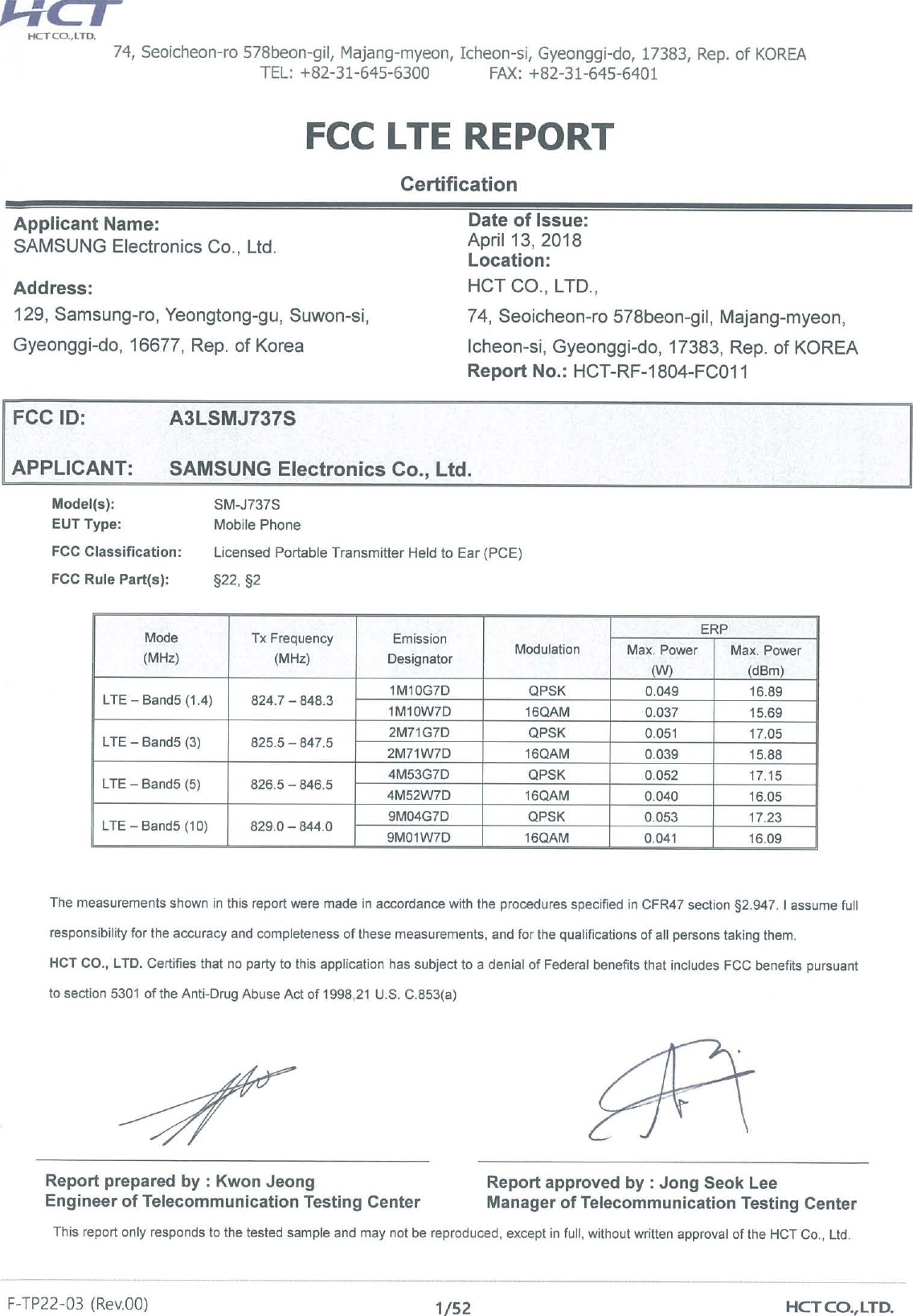

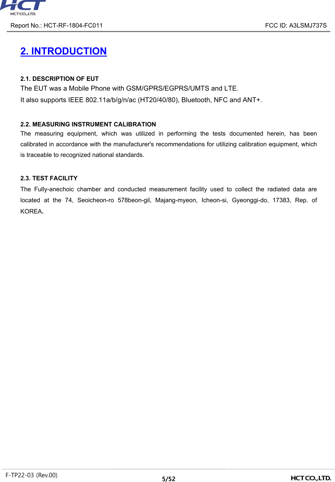
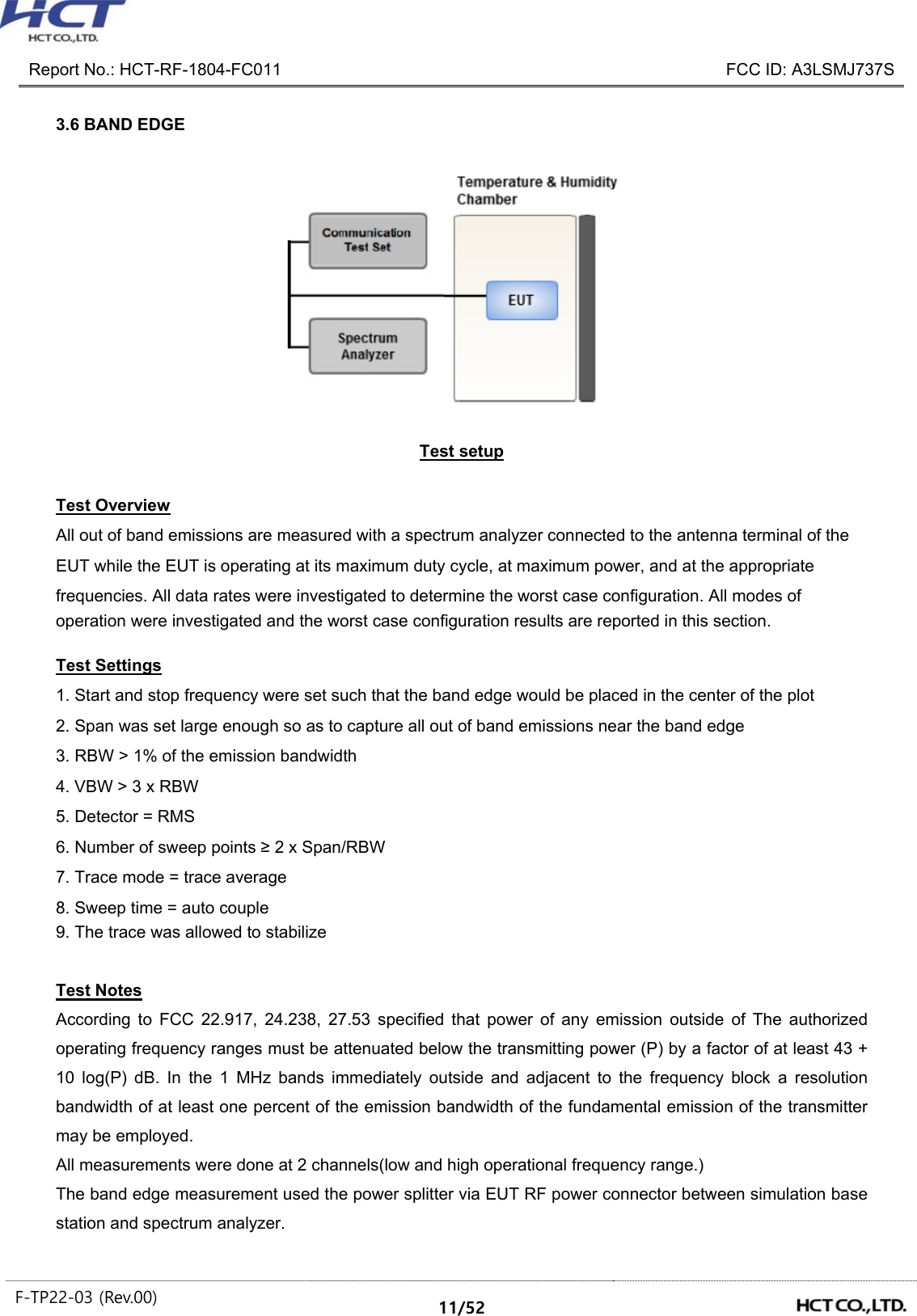
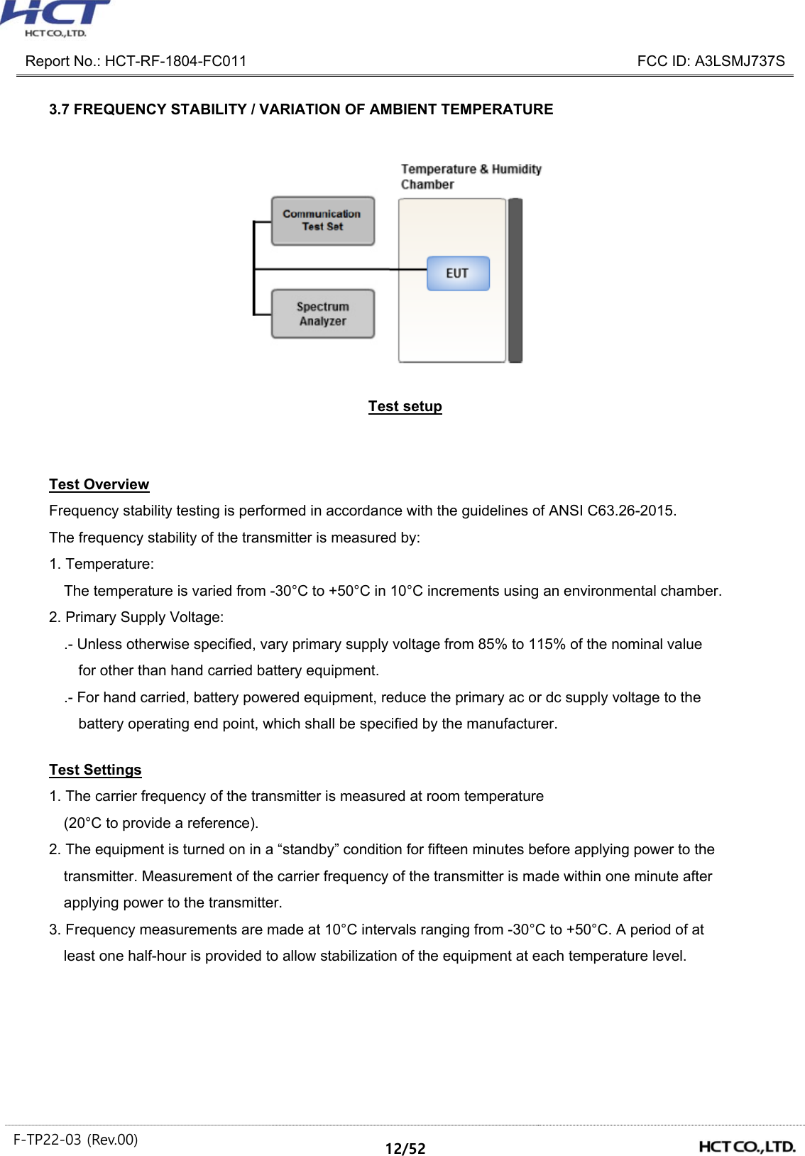
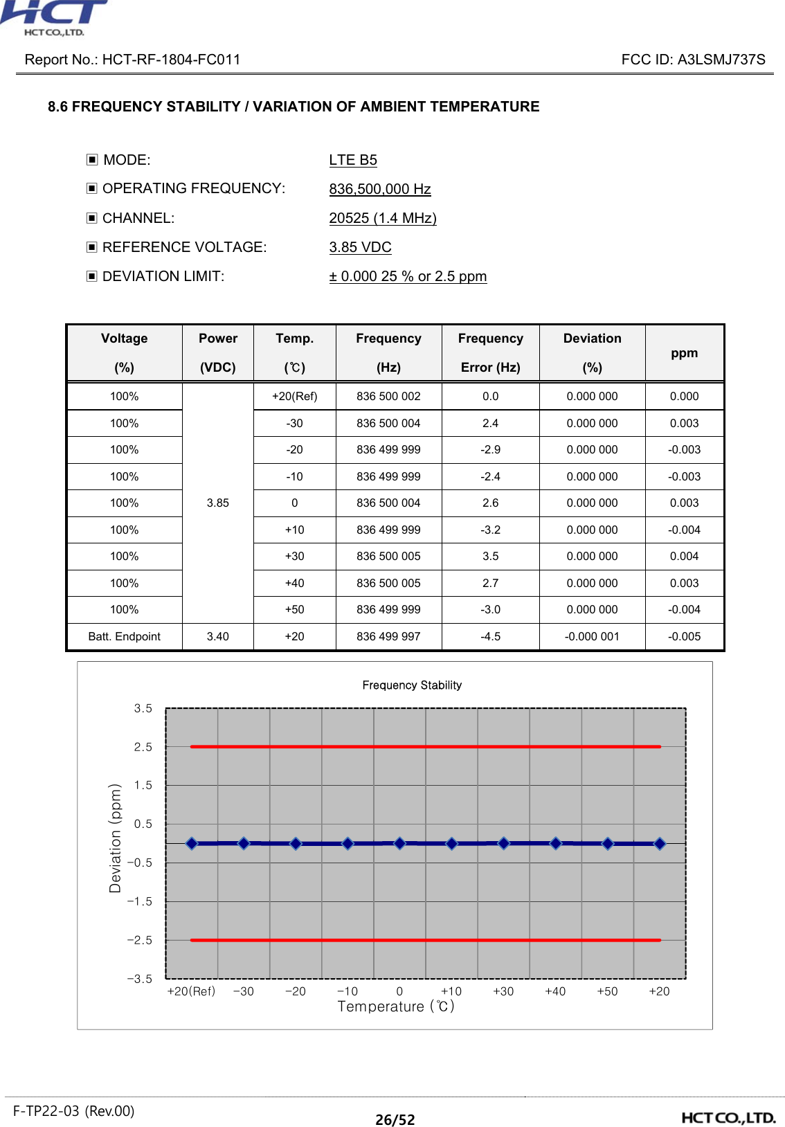
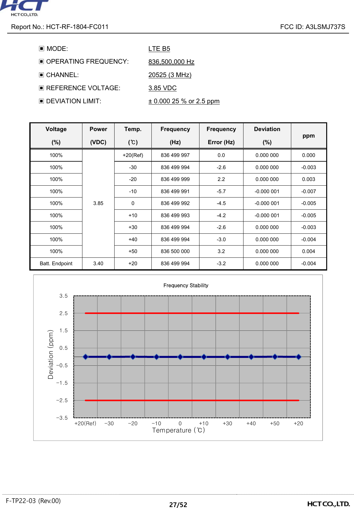
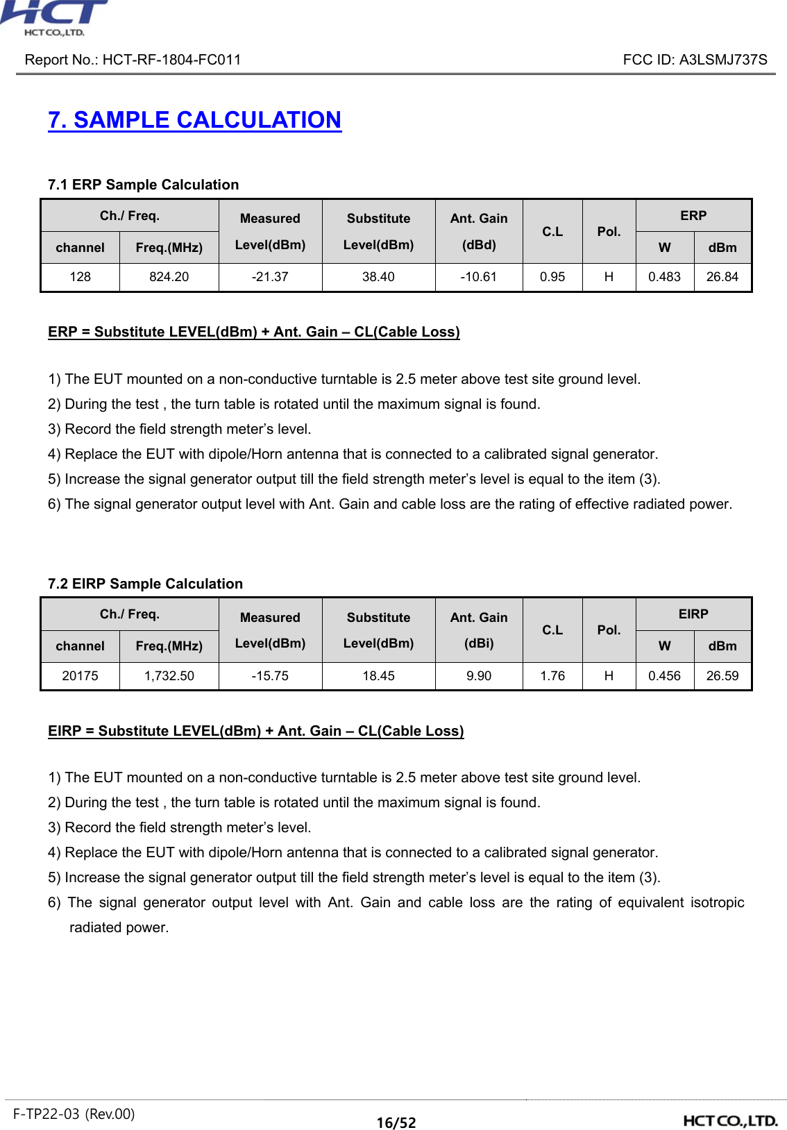
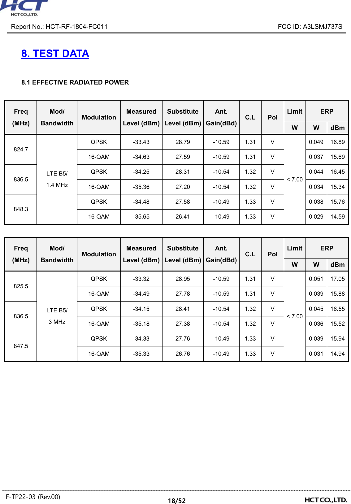
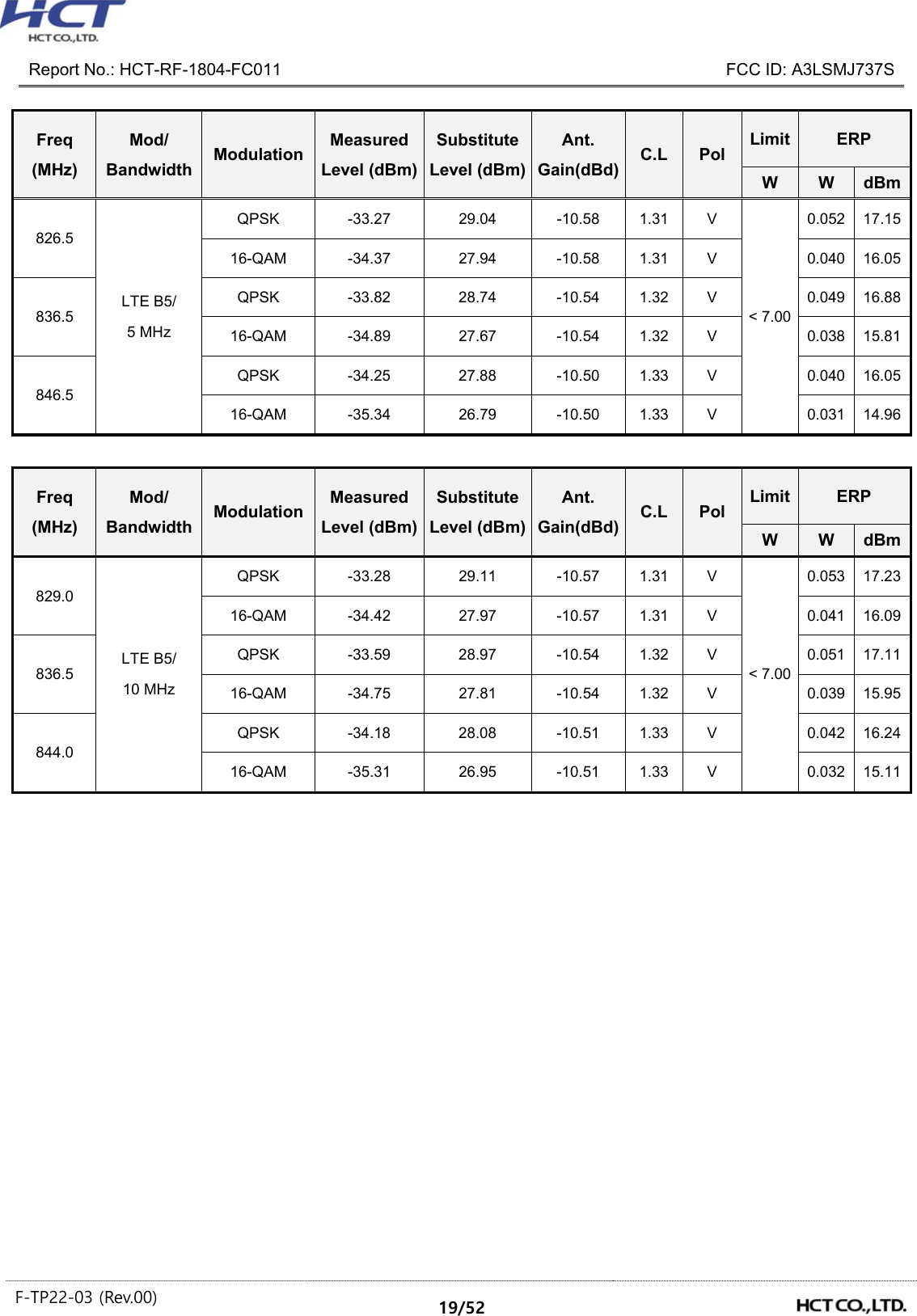
![Report No.: HCT-RF-1804-FC011 FCC ID: A3LSMJ737S F-TP22-03 (Rev.00) 15/52 6. SUMMARY OF TEST RESULTS 6.1 Test Condition : Conducted Test Test Description FCC Part Section(s) Test Limit Test Result Occupied Bandwidth §2.1049 N/A PASS Band Edge / Spurious and Harmonic Emissions at Antenna Terminal. §2.1051, §22.917(a) < 43 + 10log10 (P[Watts]) at Band Edge and for all out-of-band emissions PASS Conducted Output Power §2.1046 N/A See Note1 Frequency stability / variation of ambient temperature §2.1055, §22.355 < 2.5 ppm PASS Note: 1. See SAR Report 6.2 Test Condition : Radiated Test Test Description FCC Part Section(s) Test Limit Test Result Effective Radiated Power §22.913(a)(5) < 7 Watts max. ERP PASS Radiated Spurious and Harmonic Emissions §2.1053, §22.917(a) < 43 + 10log10 (P[Watts]) for all out-of band emissions PASS](https://usermanual.wiki/Samsung-Electronics-Co/SMJ737S.Test-Report-20180417-v1-SM-J737S-Test-Report-LTE5/User-Guide-3825947-Page-15.png)
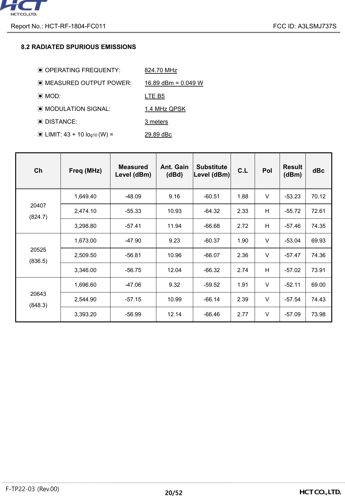
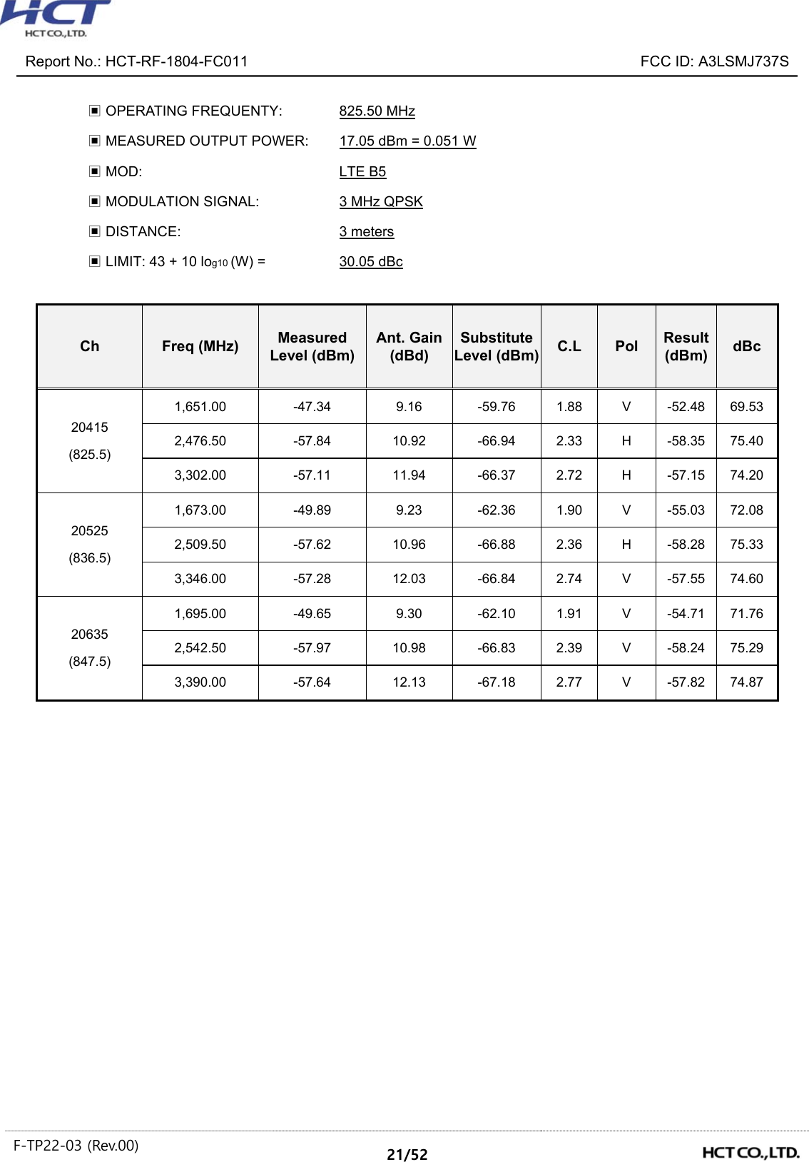


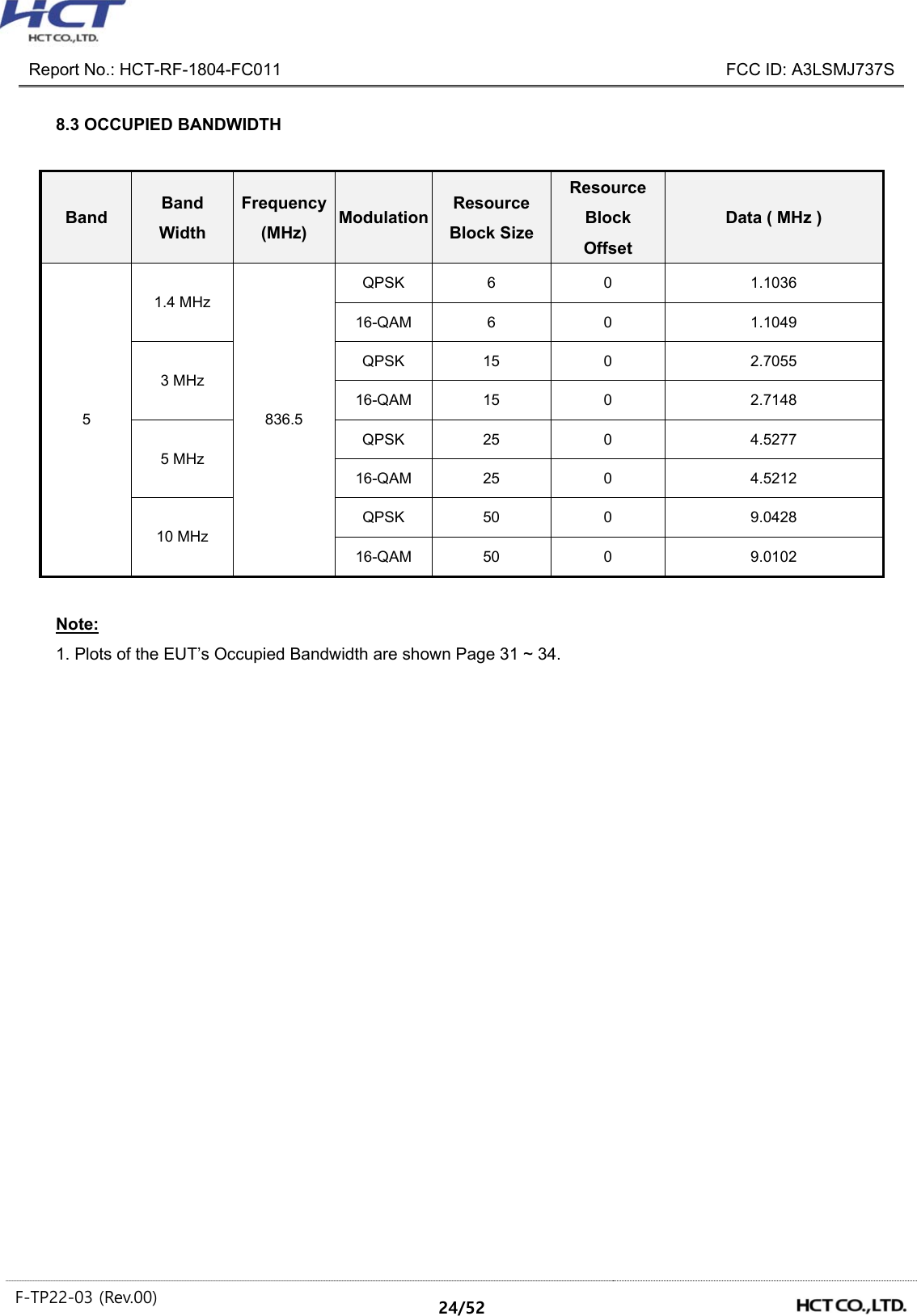
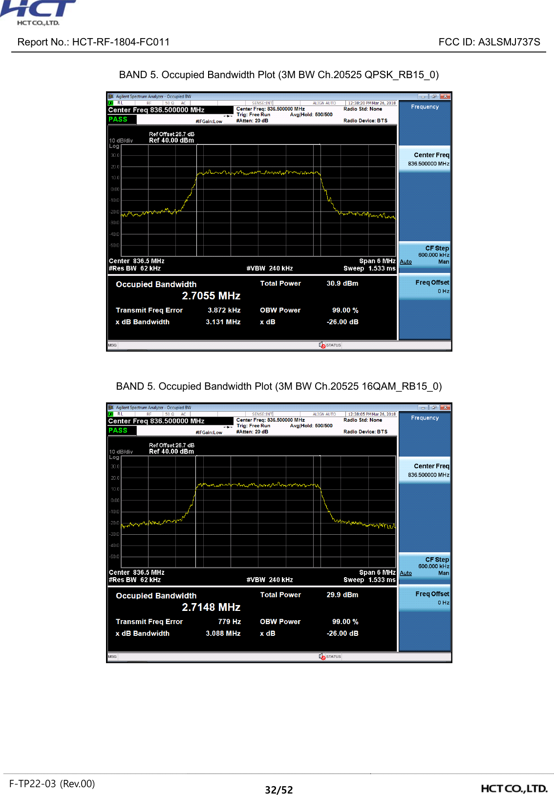
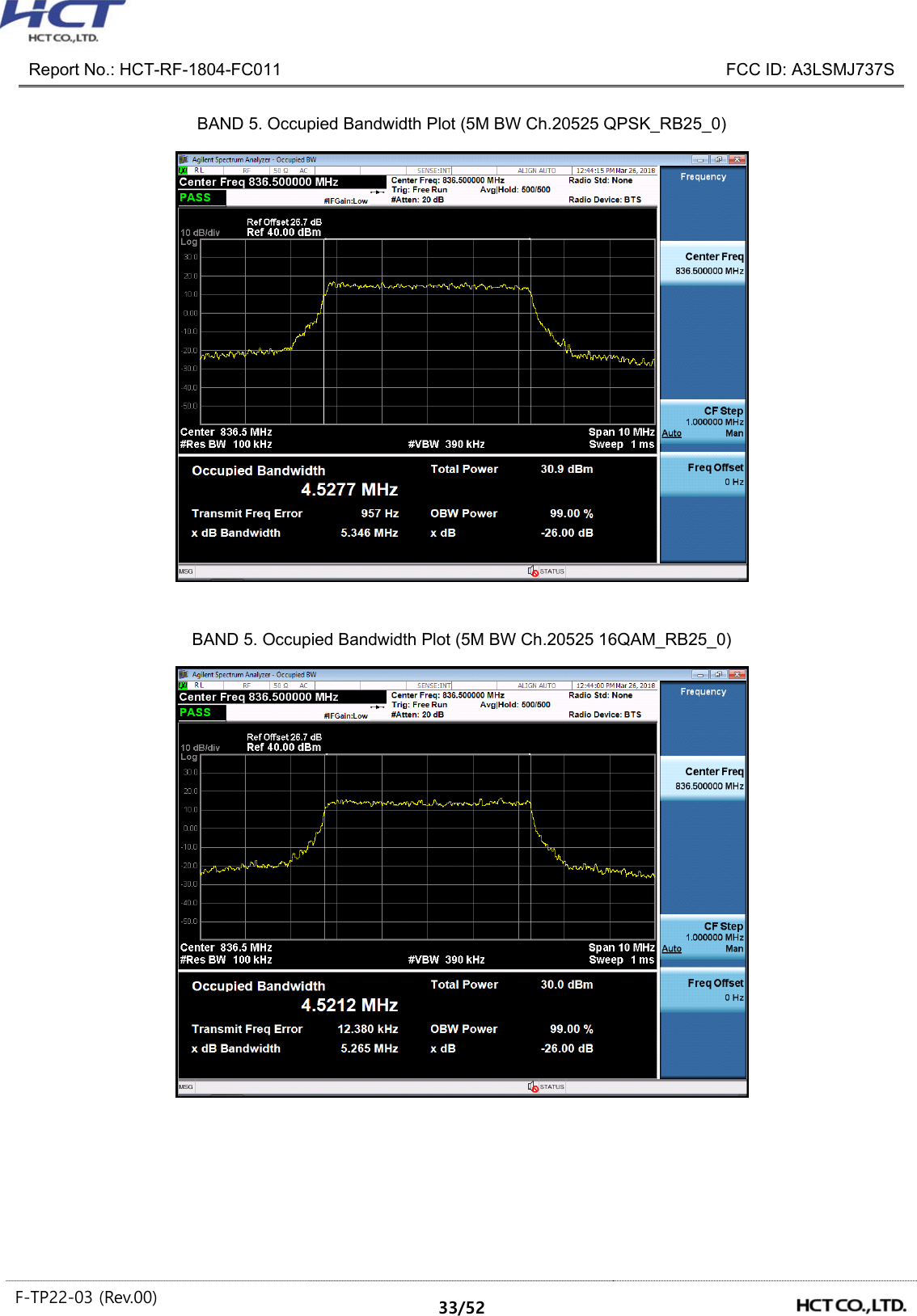
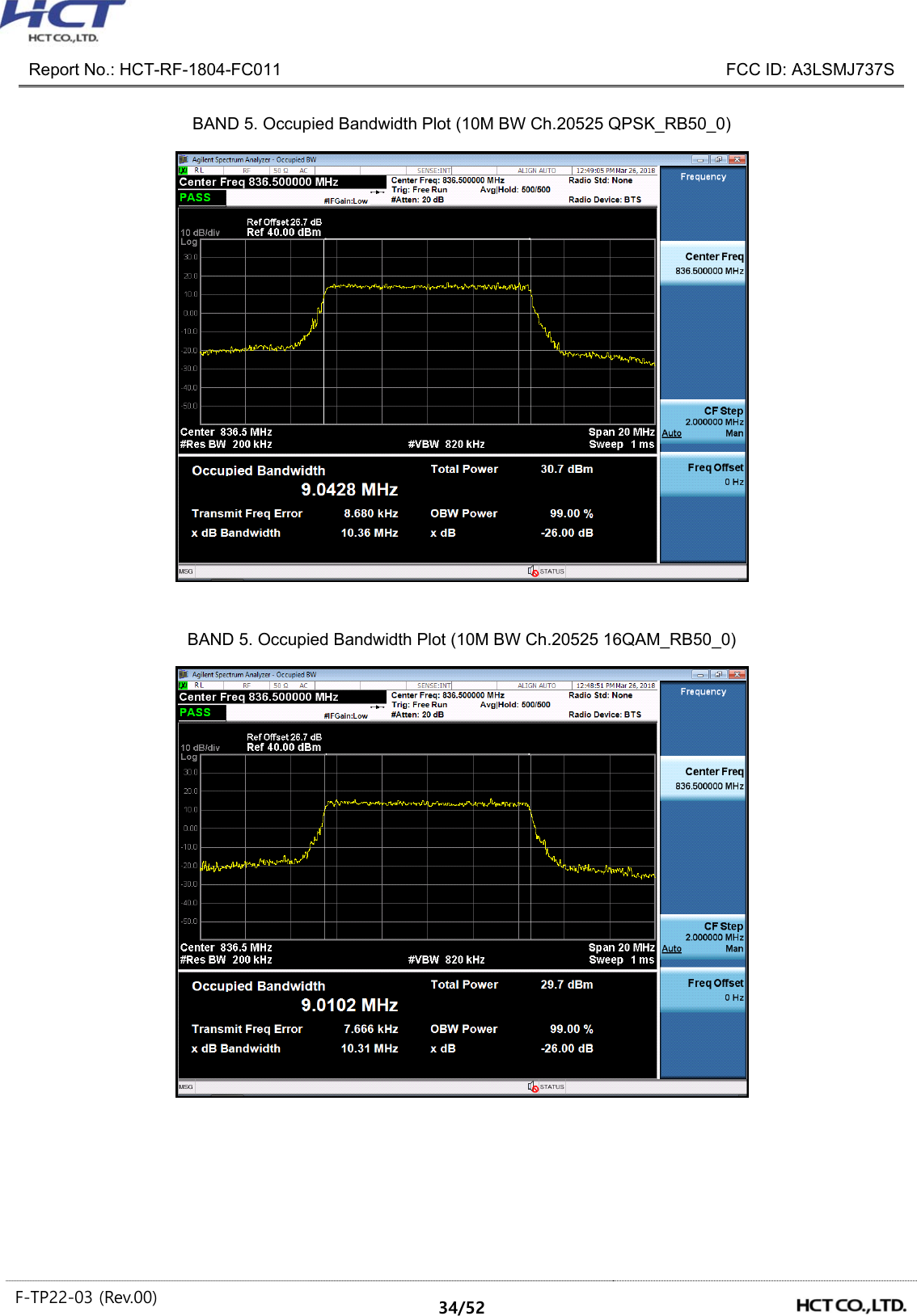
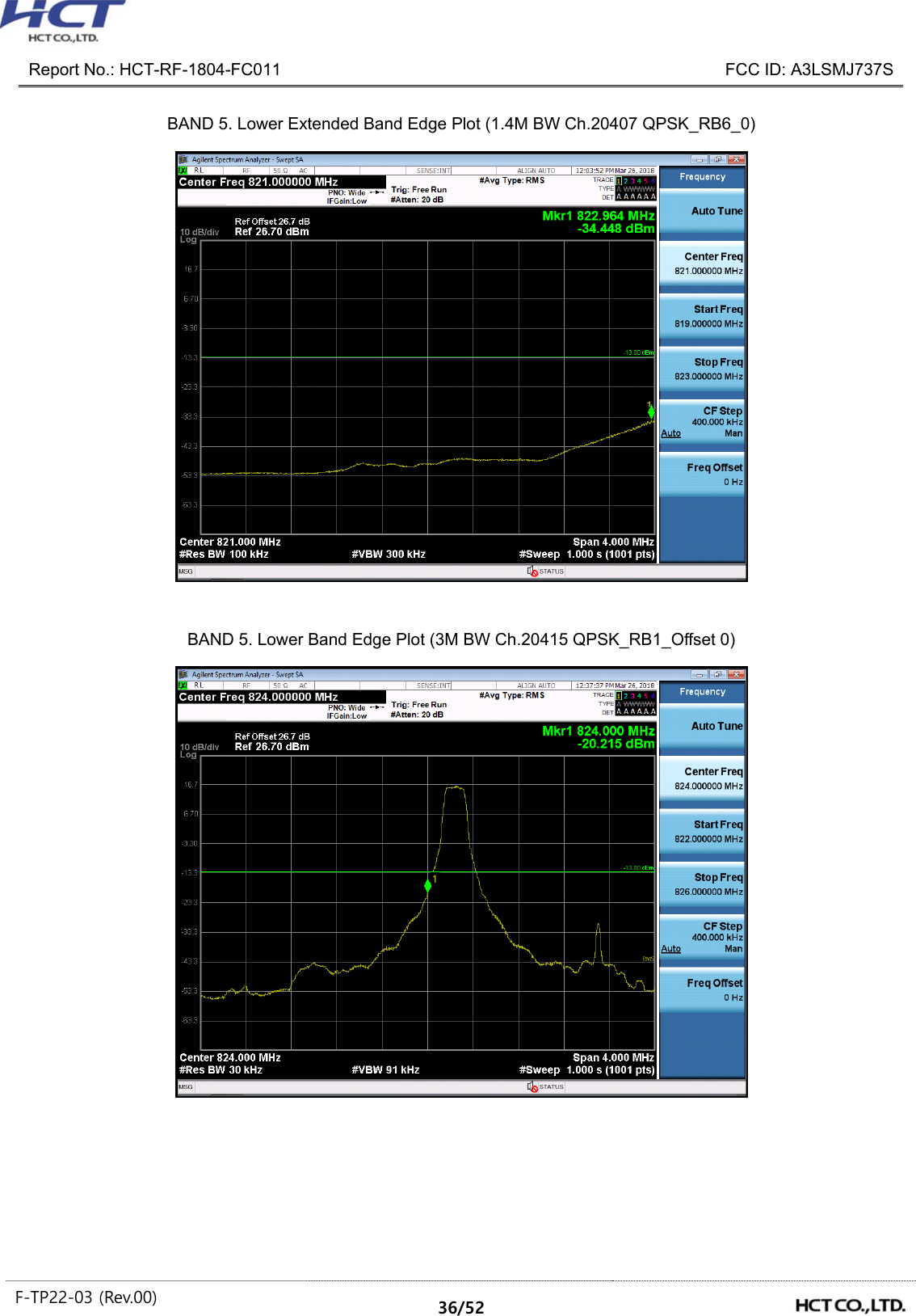
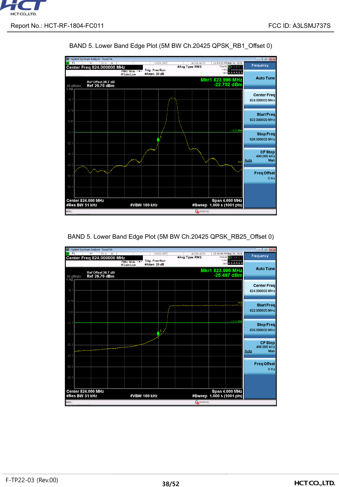
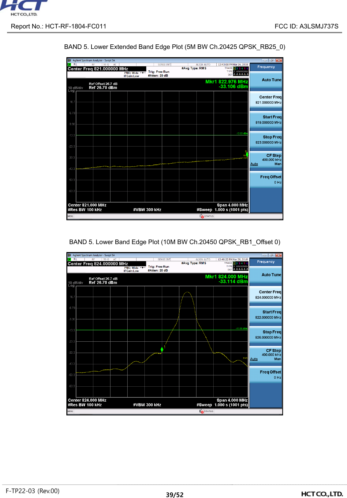
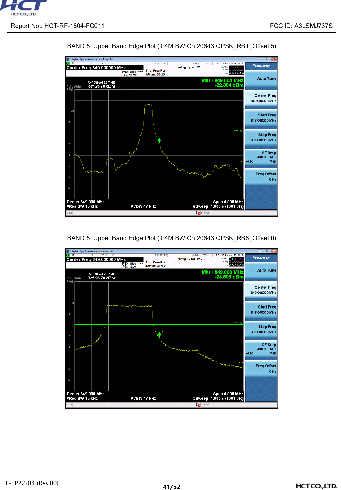
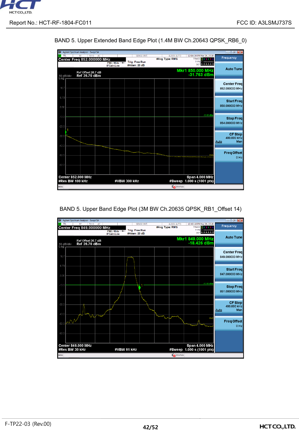
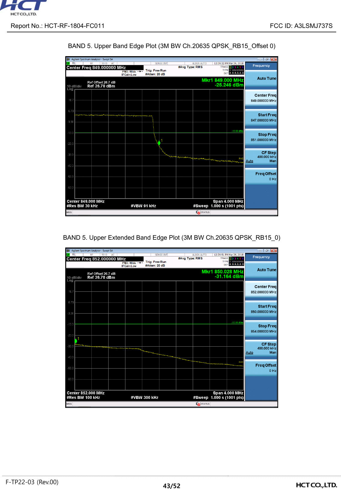
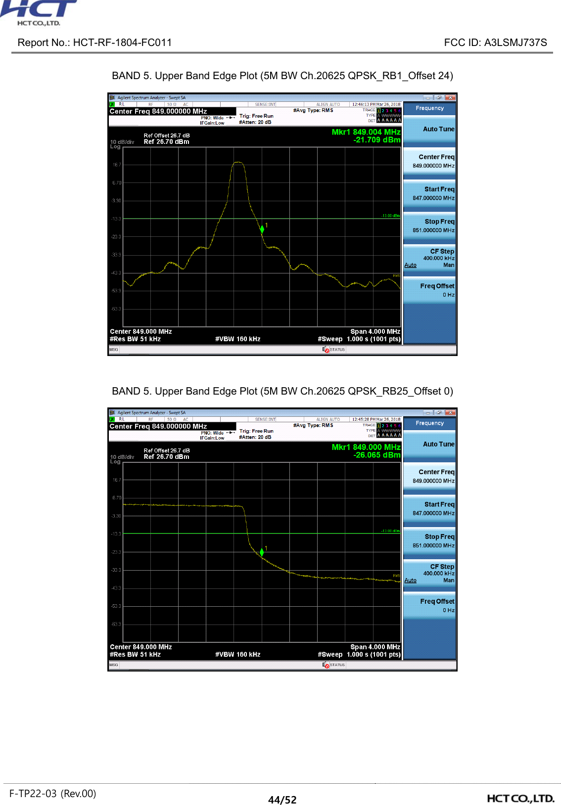
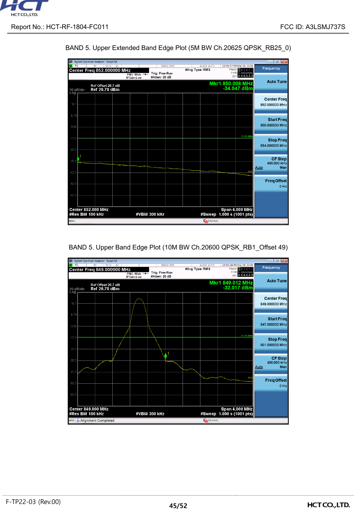
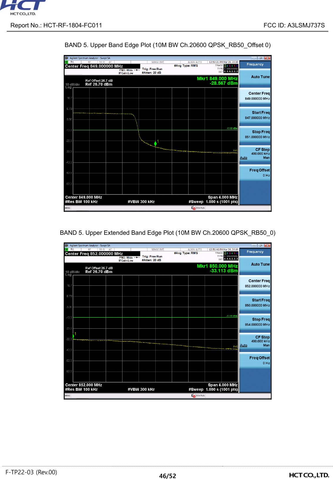
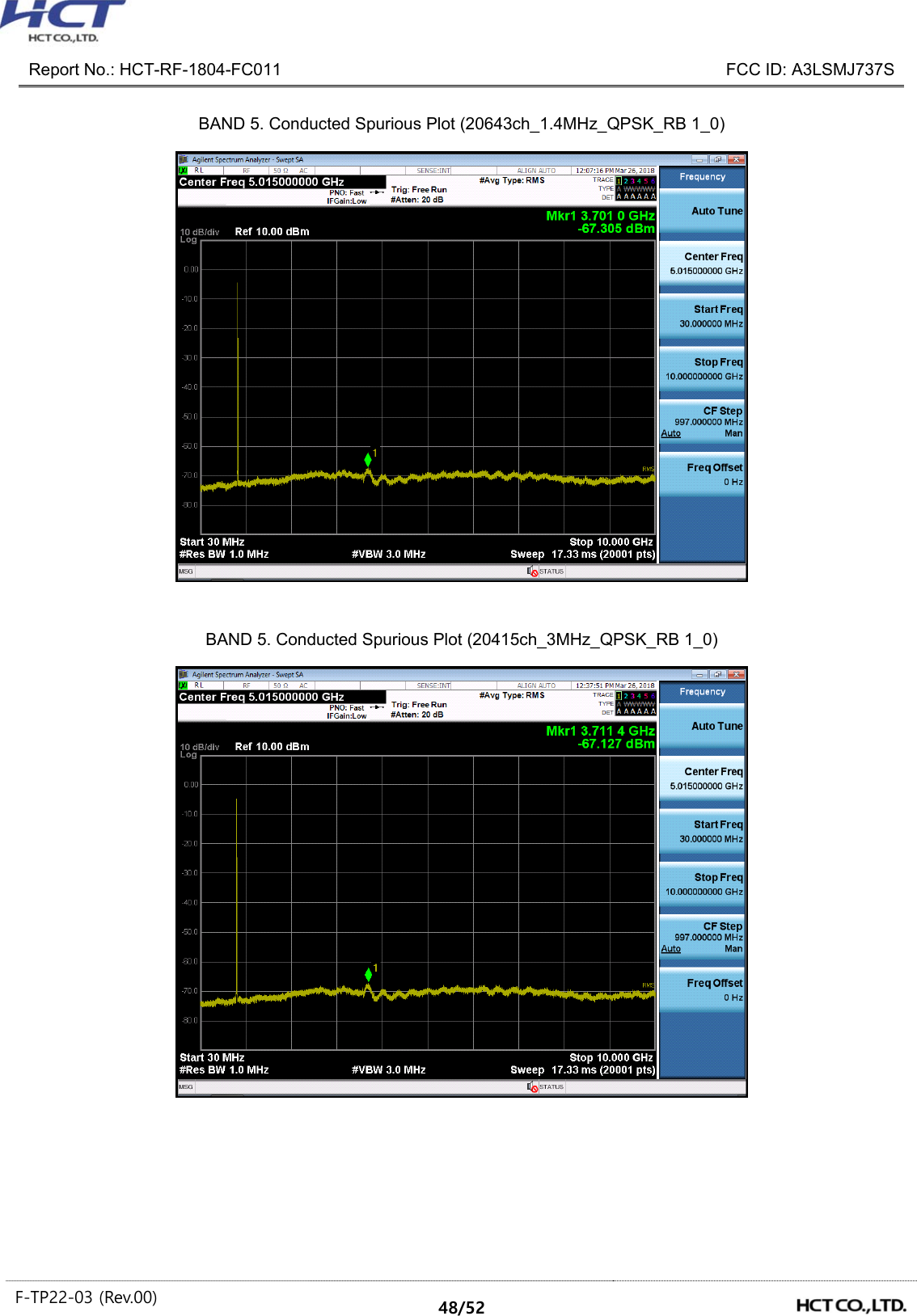
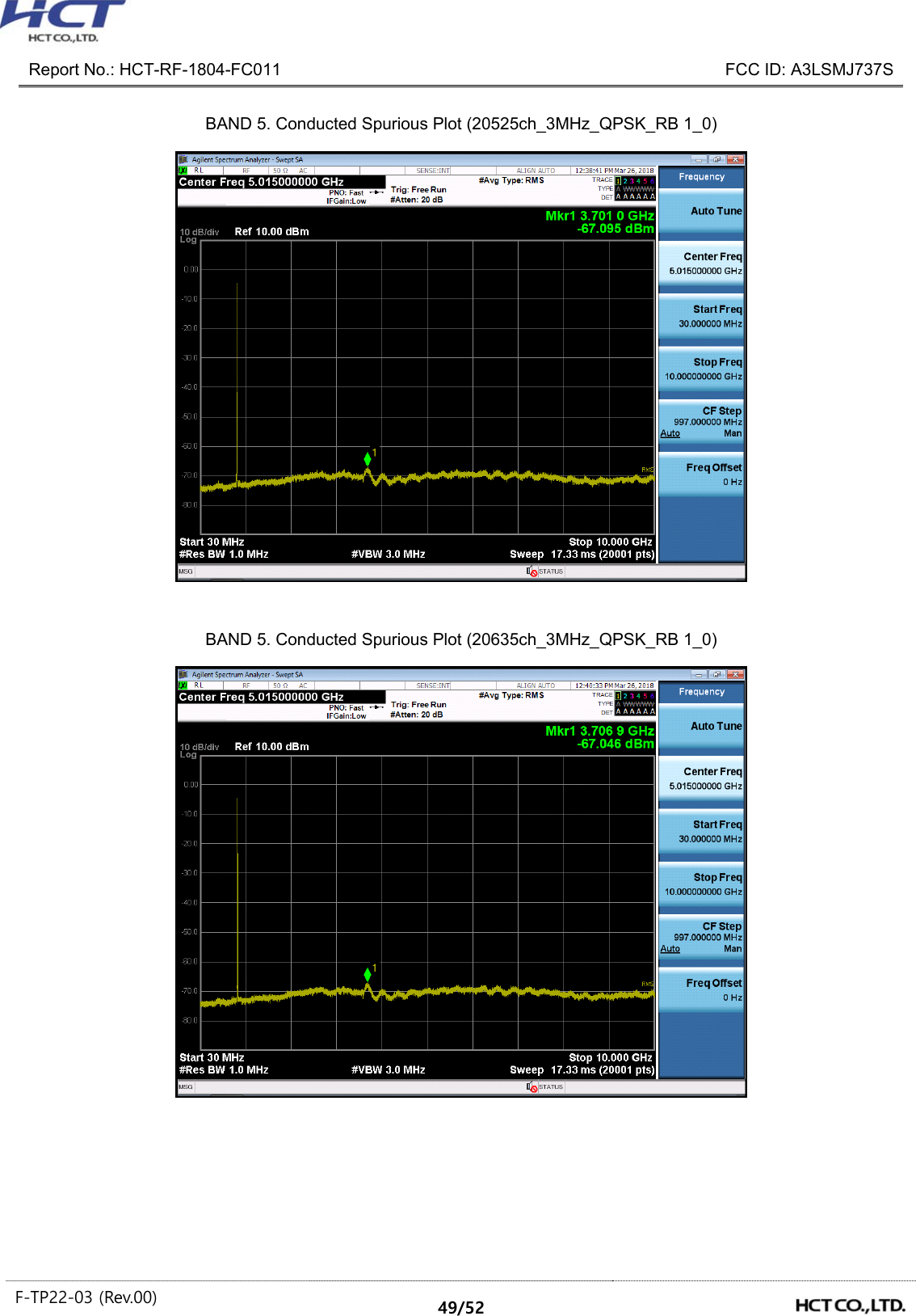
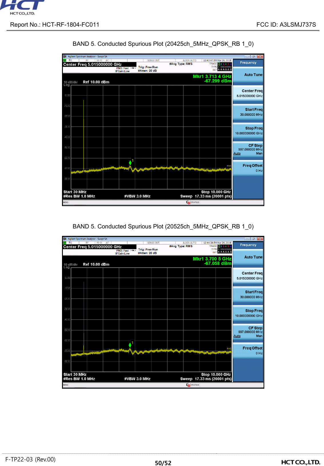
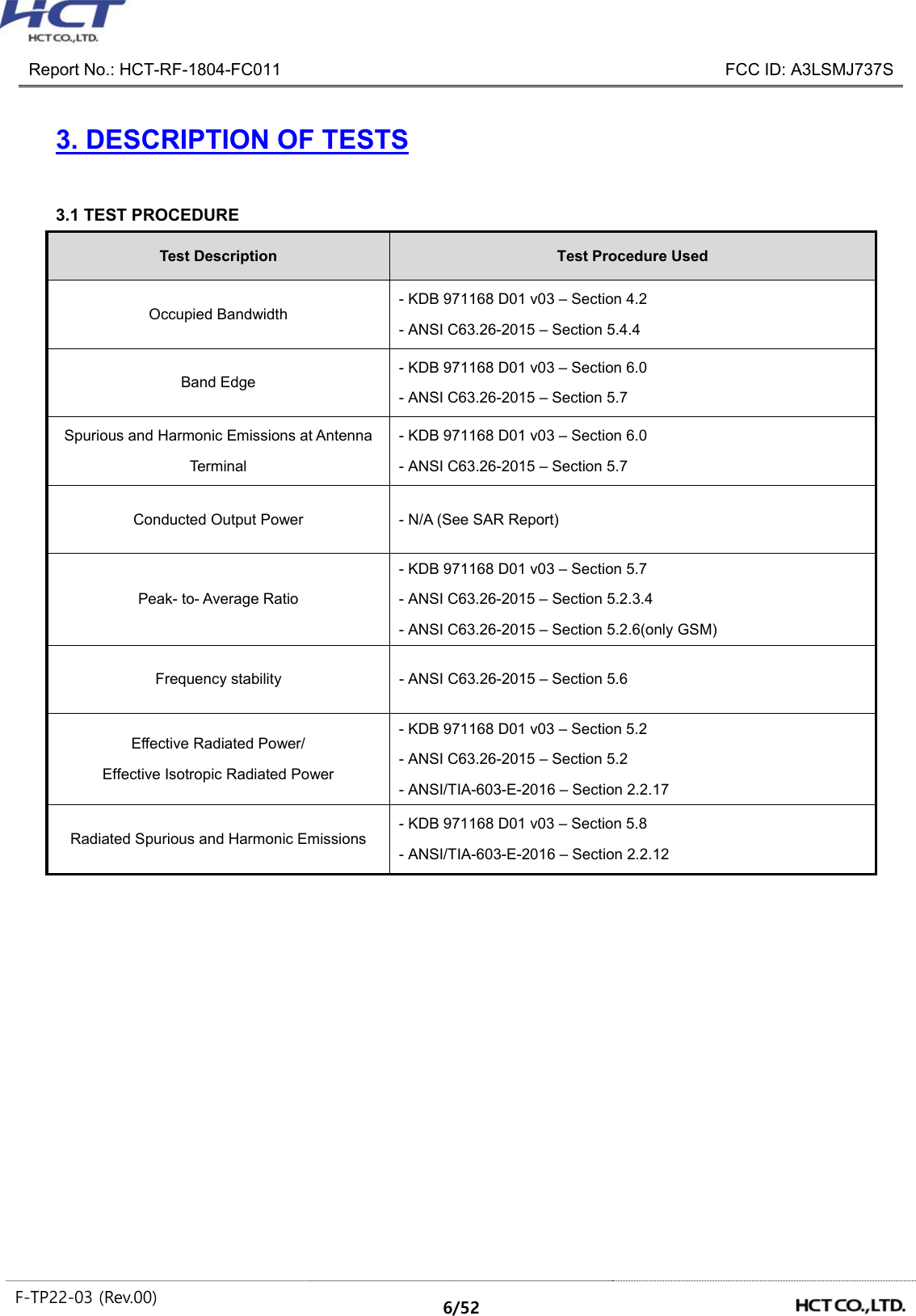
![Report No.: HCT-RF-1804-FC011 FCC ID: A3LSMJ737S F-TP22-03 (Rev.00) 25/52 8.4 CONDUCTED SPURIOUS EMISSIONS Band Band Width (MHz) Frequency (MHz) Frequency of Maximum Harmonic (GHz) Factor (dB) Measurement Maximum Data (dBm) Result (dBm) Limit (dBm) 5 1.4 824.7 3.7239 27.976 -67.372 -39.396 -13.00 836.5 3.1805 27.976 -66.997 -39.021 848.3 3.7010 27.976 -67.305 -39.329 3 825.5 3.7114 27.976 -67.127 -39.151 836.5 3.7010 27.976 -67.095 -39.119 847.5 3.7069 27.976 -67.046 -39.070 5 826.5 3.7134 27.976 -67.299 -39.323 836.5 3.7005 27.976 -67.058 -39.082 846.5 3.7104 27.976 -67.234 -39.258 10 829.0 3.6930 27.976 -67.127 -39.151 836.5 3.6840 27.976 -67.136 -39.160 844.0 3.6985 27.976 -67.320 -39.344 Note: 1. Plots of the EUT’s Conducted Spurious Emissions are shown Page 47 ~ 52. 2. Conducted Spurious Emissions was Tested QPSK Modulation, Resource Block Size 1 and Resource Block Offset 0 3. Result (dBm) = Measurement Maximum Data (dBm) + Factor (dB) 4. Factor(dB) = Cable Loss + Attenuator + Power Splitter Frequency Range (GHz) Factor [dB] 0.03 – 1 25.270 1 – 5 27.976 5 – 10 28.591 10 – 15 29.116 15 – 20 29.489 Above 20 30.131 8.5 BAND EDGE - Plots of the EUT’s Band Edge are shown Page 35 ~ 46.](https://usermanual.wiki/Samsung-Electronics-Co/SMJ737S.Test-Report-20180417-v1-SM-J737S-Test-Report-LTE5/User-Guide-3825947-Page-25.png)