Samsung Electronics Co SMM-2CR0480800 Remote Radio Head User Manual
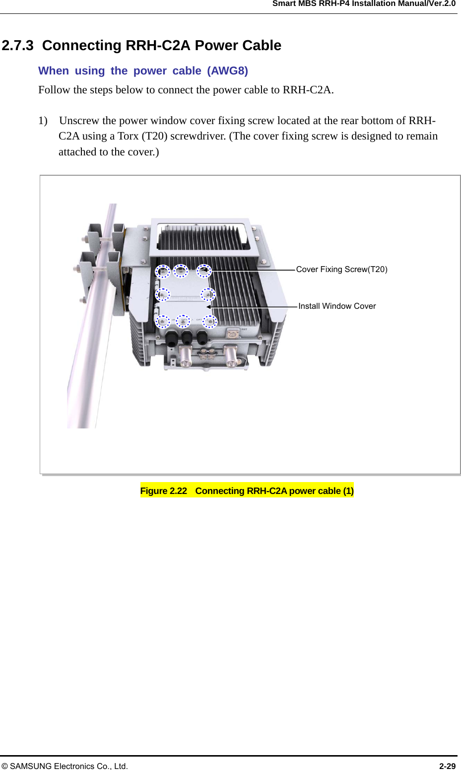
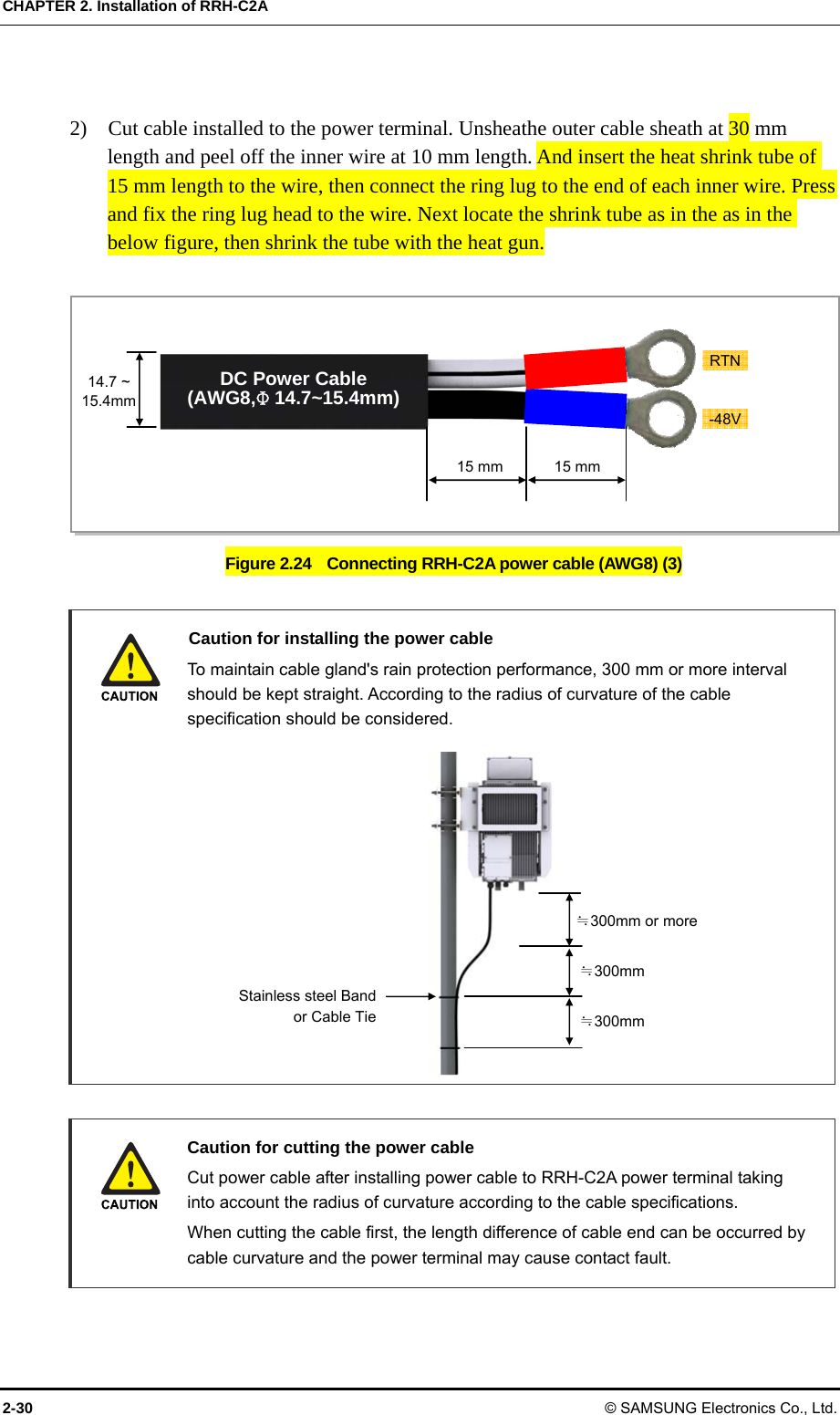
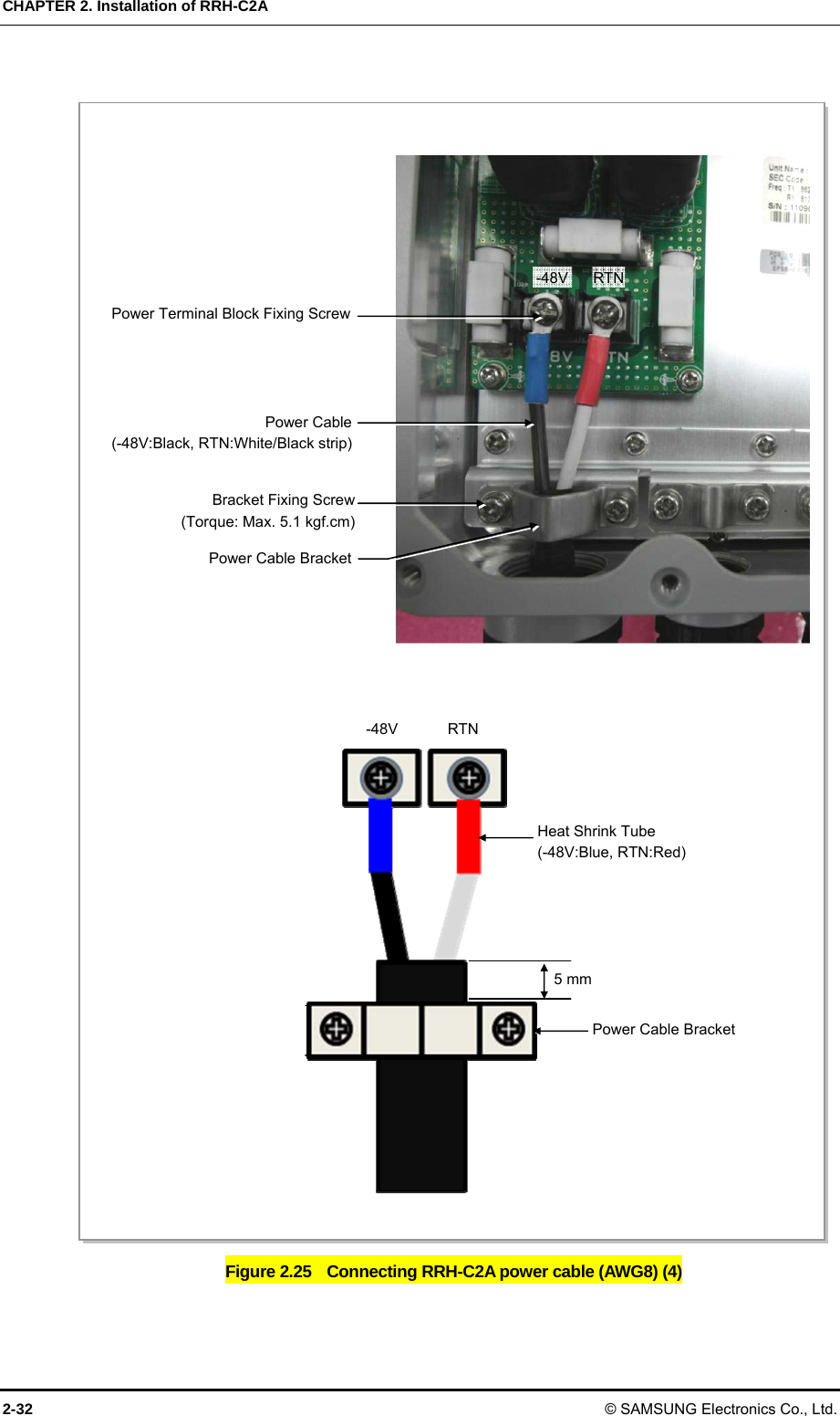
Samsung Electronics Co Ltd Remote Radio Head
UserManual.wiki
>
Samsung Electronics Co
>
SMM-2CR0480800 User Manual
>
User manual
Contents
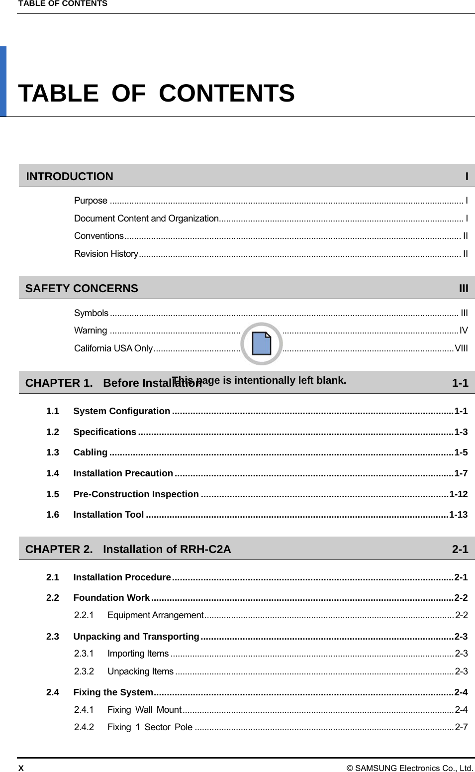
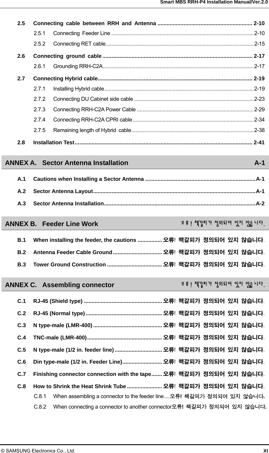
1.
User manual
2.
user manual
User manual
Navigation menu
Upload a User Manual
Namespaces
Wiki Guide
HTML
PDF
Info
Views
User Manual
Discussion / Help
Navigation
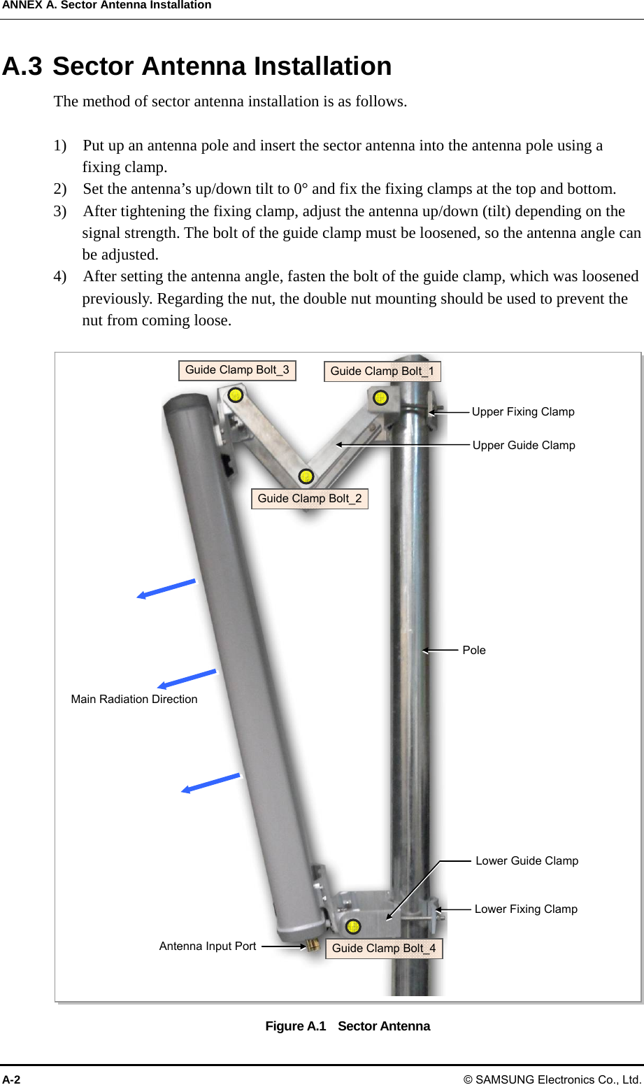
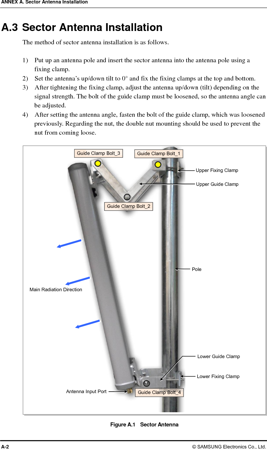
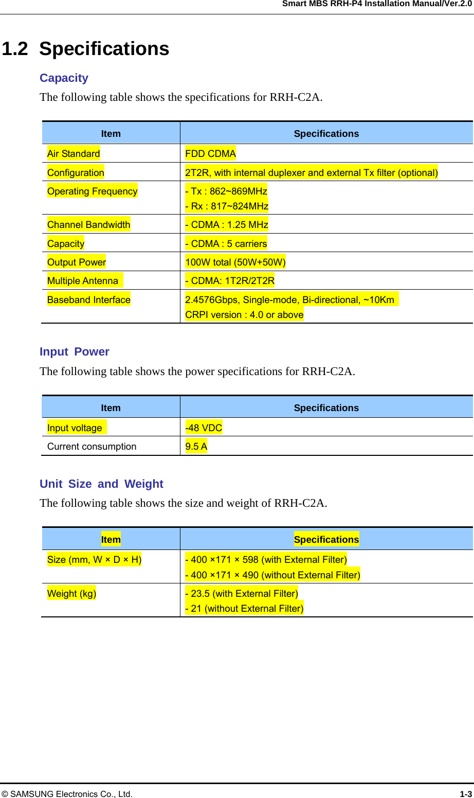
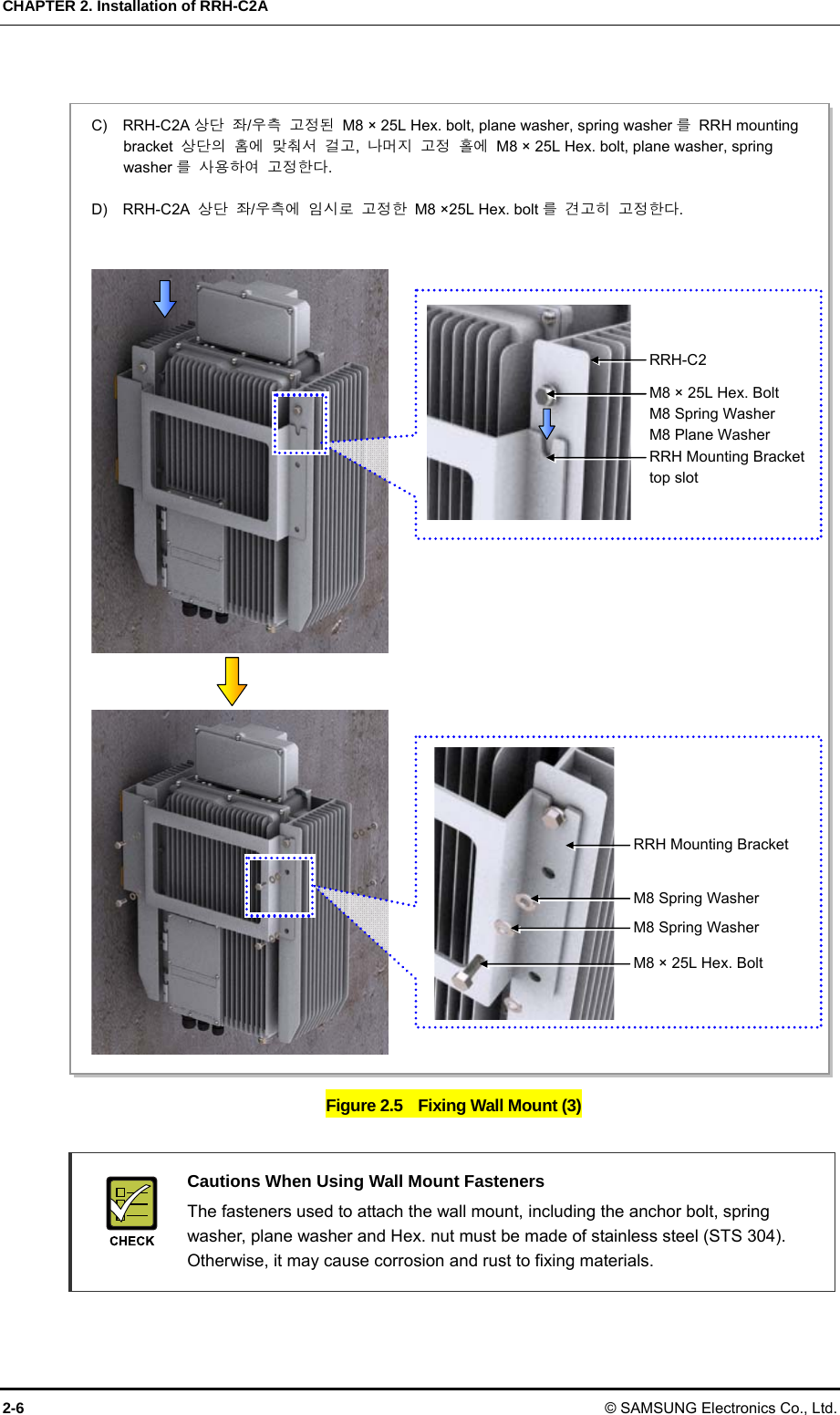
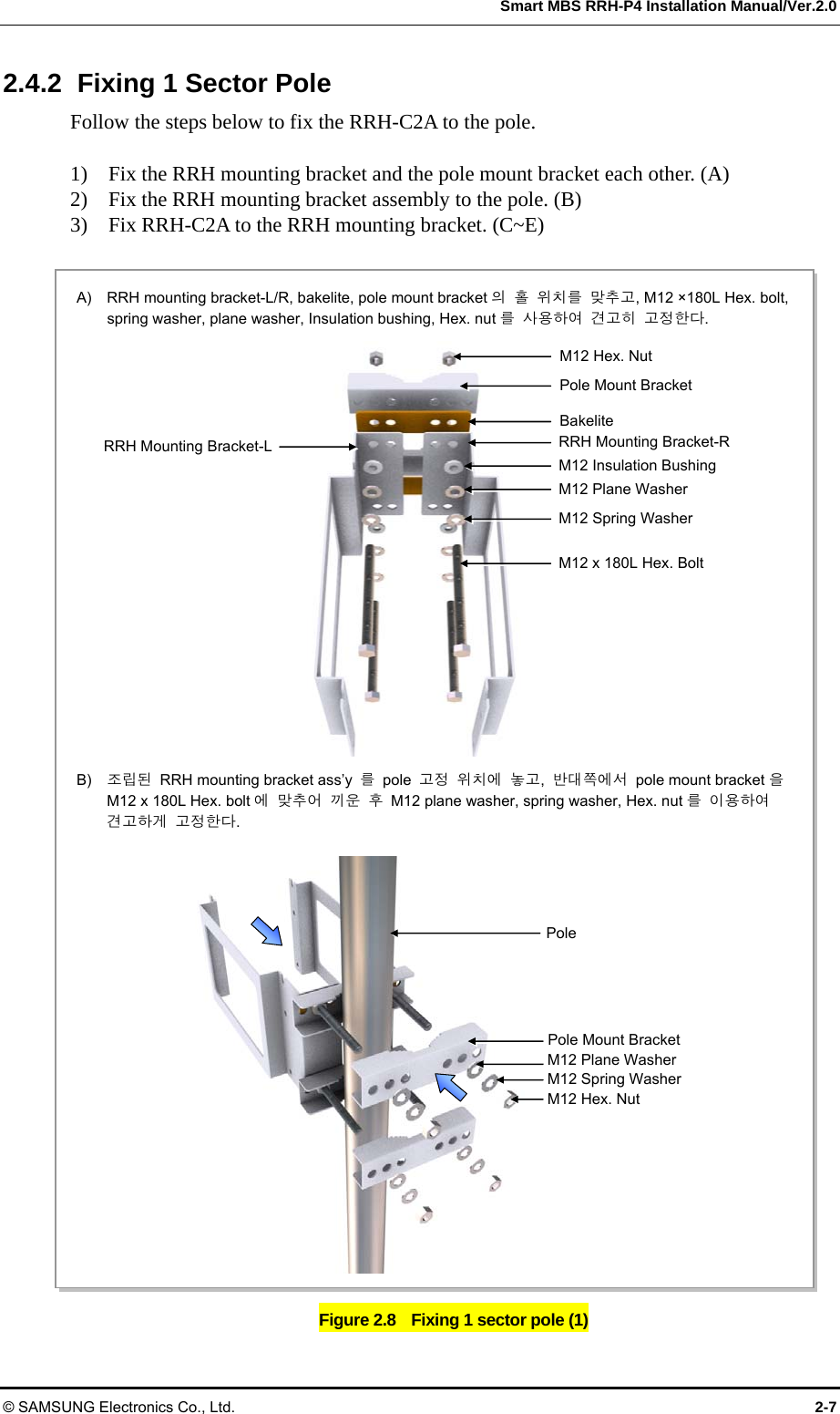
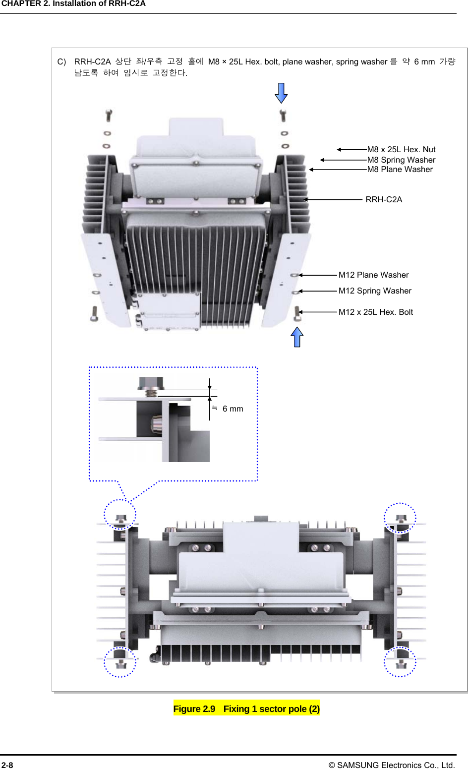
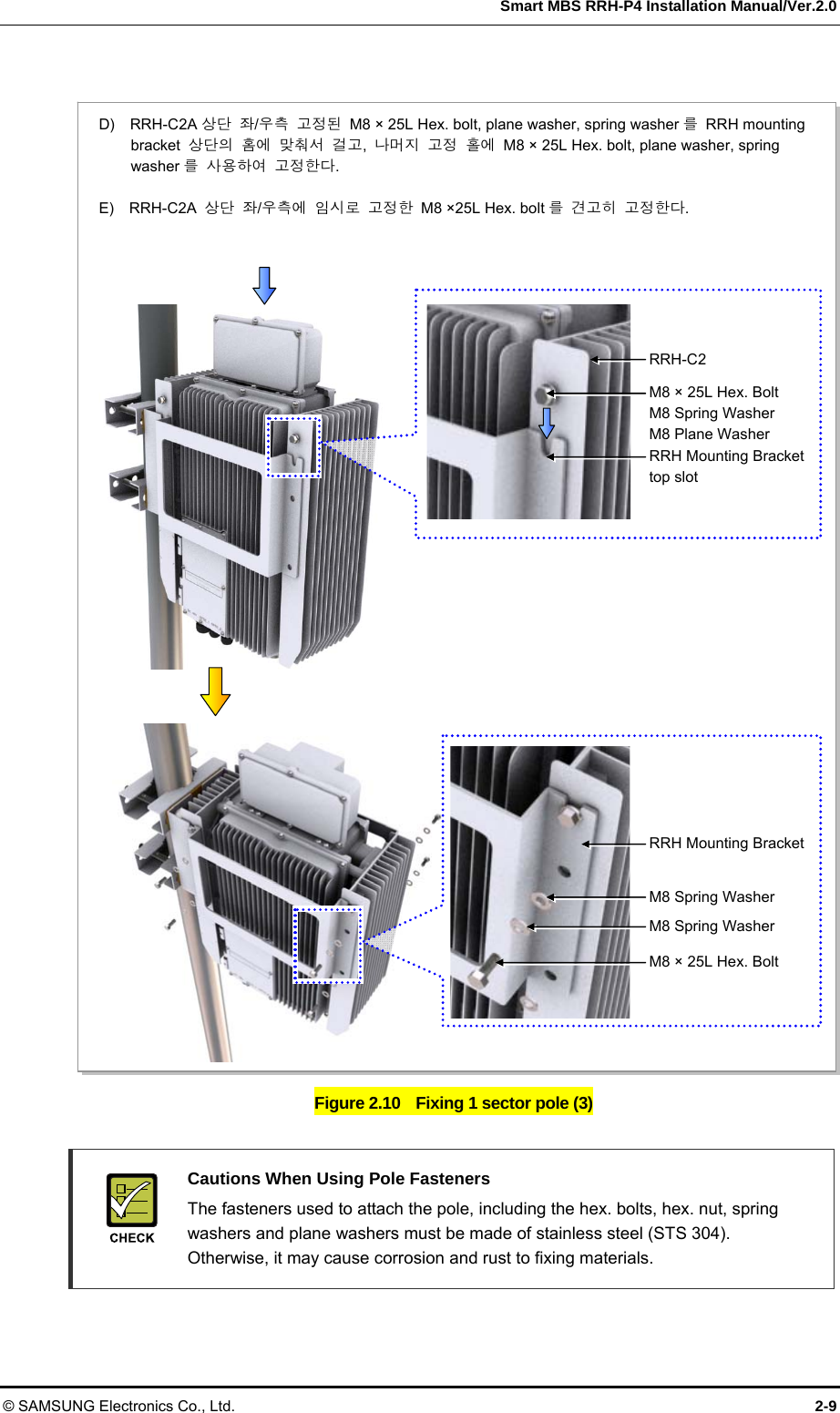
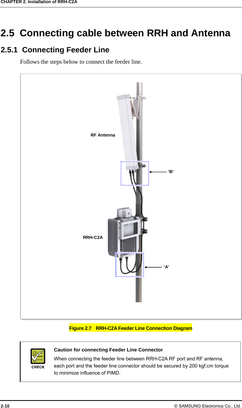
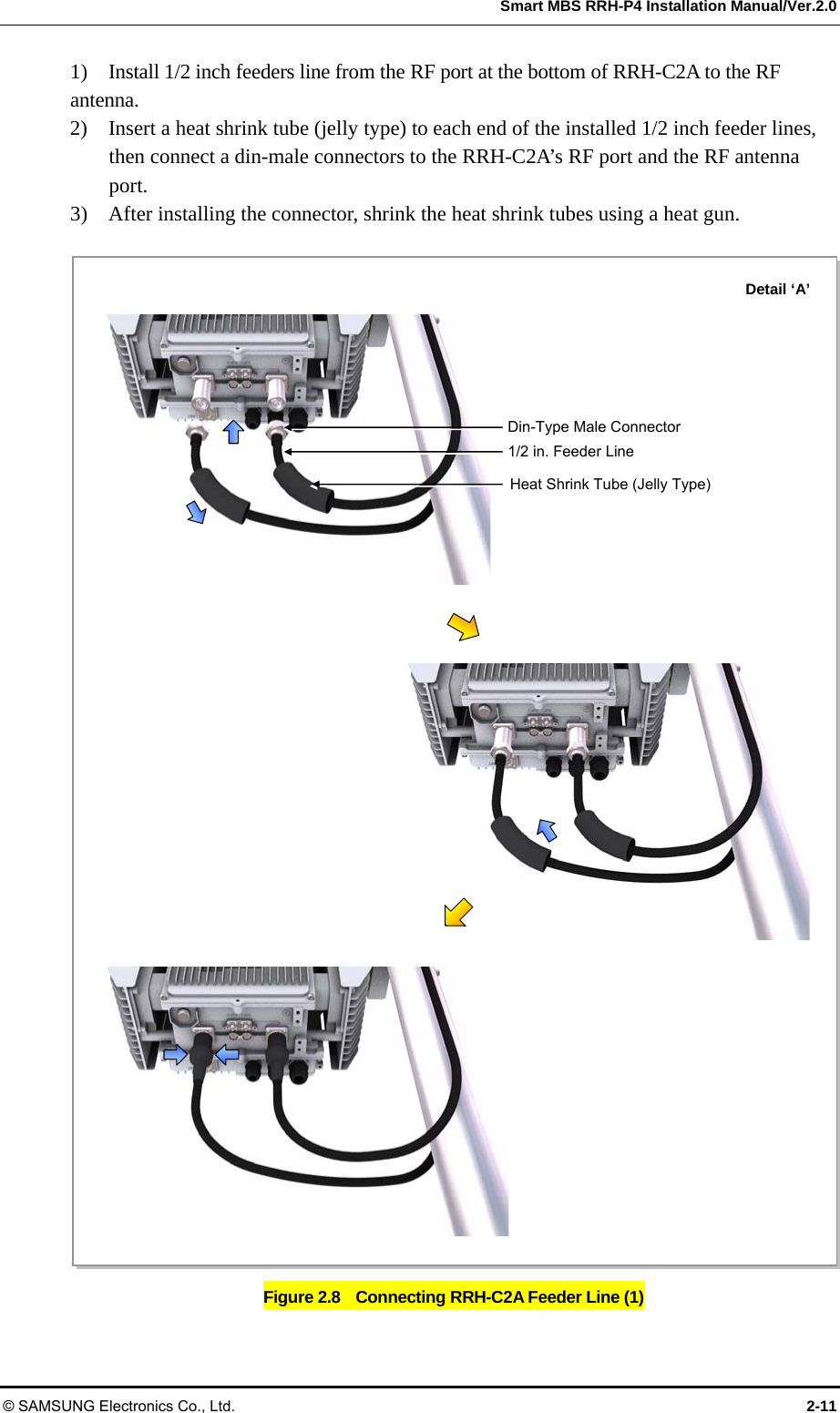
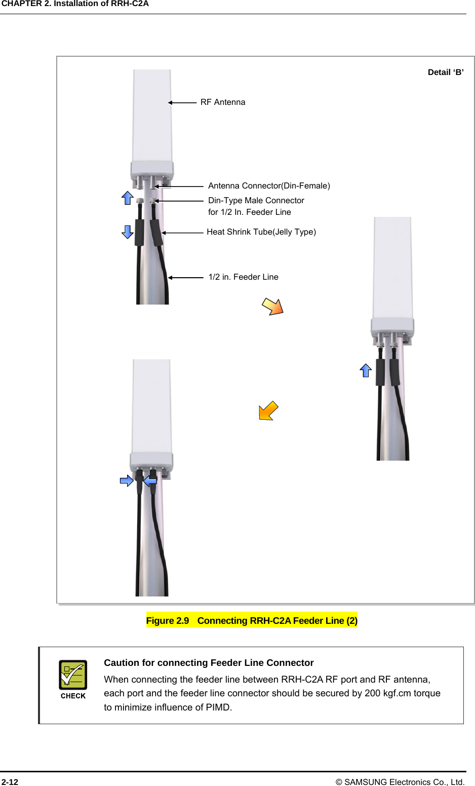
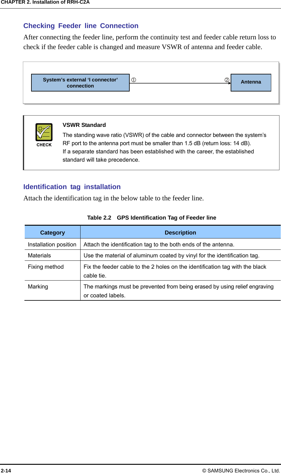
![Smart MBS RRH-P4 Installation Manual © SAMSUNG Electronics Co., Ltd. 1-1 CHAPTER 1. Before Installation 1.1 System Configuration RRH-C2A Configuration The following shows the configuration of RRH-C2A. Figure 1.1 RRH-C2A Configuration [Top View] [Unit: mm][Front View] [Bottom View][Right View] [Left View] [Rear View] 598 171 400](https://usermanual.wiki/Samsung-Electronics-Co/SMM-2CR0480800.User-manual/User-Guide-1578505-Page-19.png)
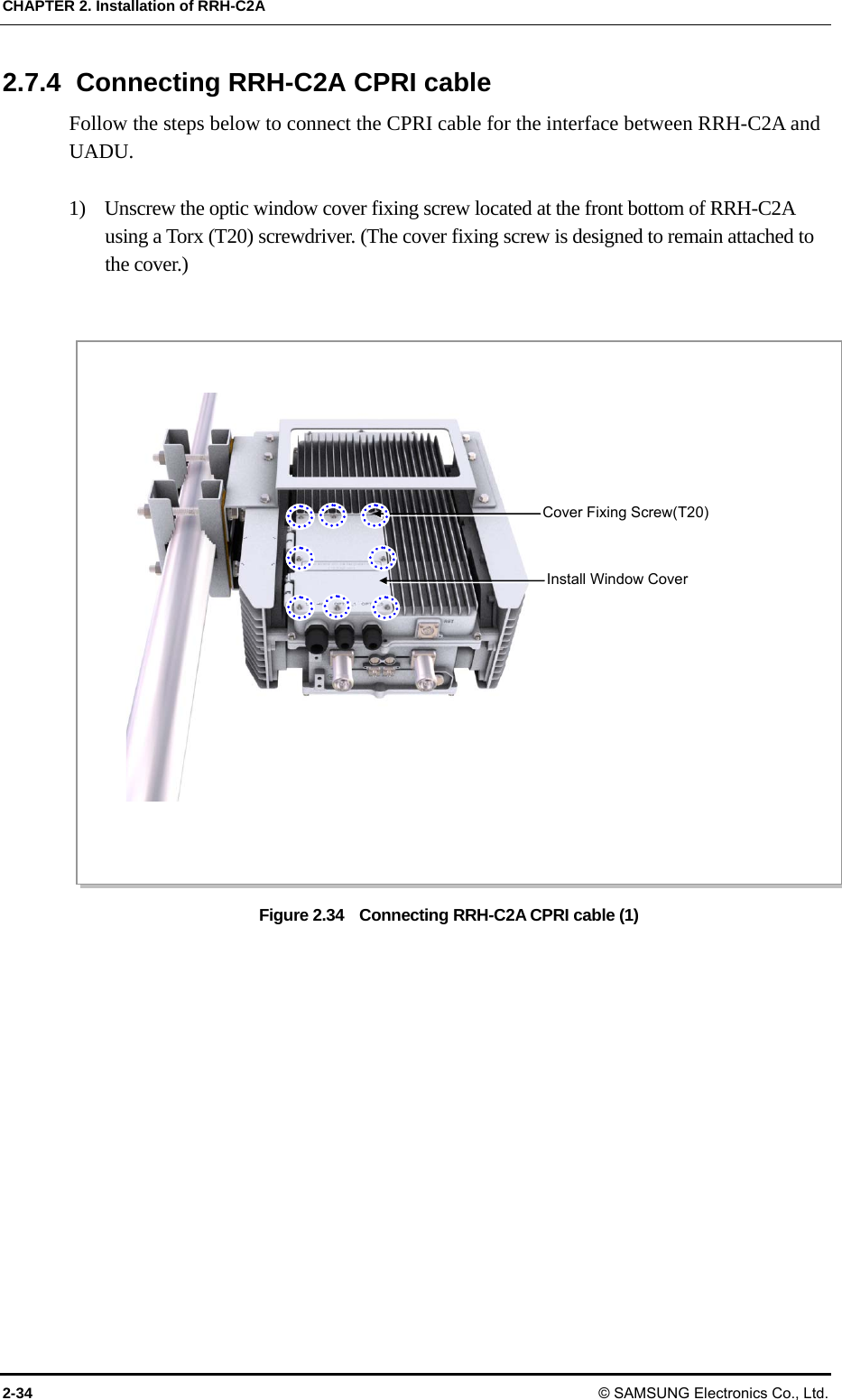
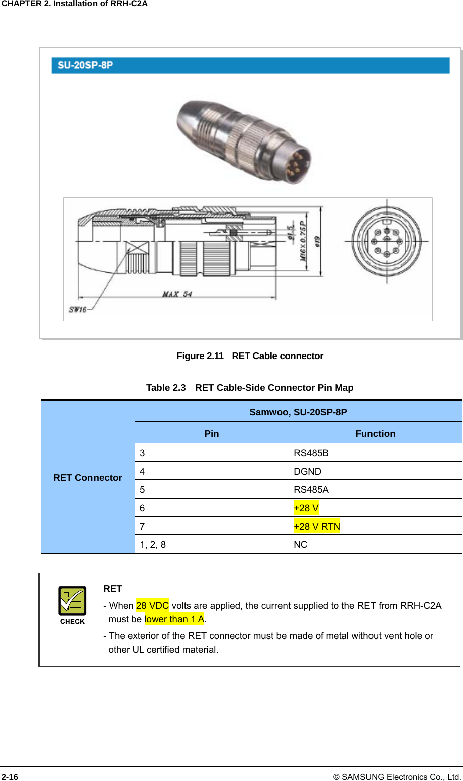
![CHAPTER 1. Before Installation 1-2 © SAMSUNG Electronics Co., Ltd. External Interfaces of RRH-C2A The following shows the external interfaces of RRH-C2A. Figure 1.2 External Interfaces of RRH-C2A [Bottom View] POWER [-48 V] OPTIC_1 RET Ground ANT 0ANT 1OPTIC_0](https://usermanual.wiki/Samsung-Electronics-Co/SMM-2CR0480800.User-manual/User-Guide-1578505-Page-20.png)
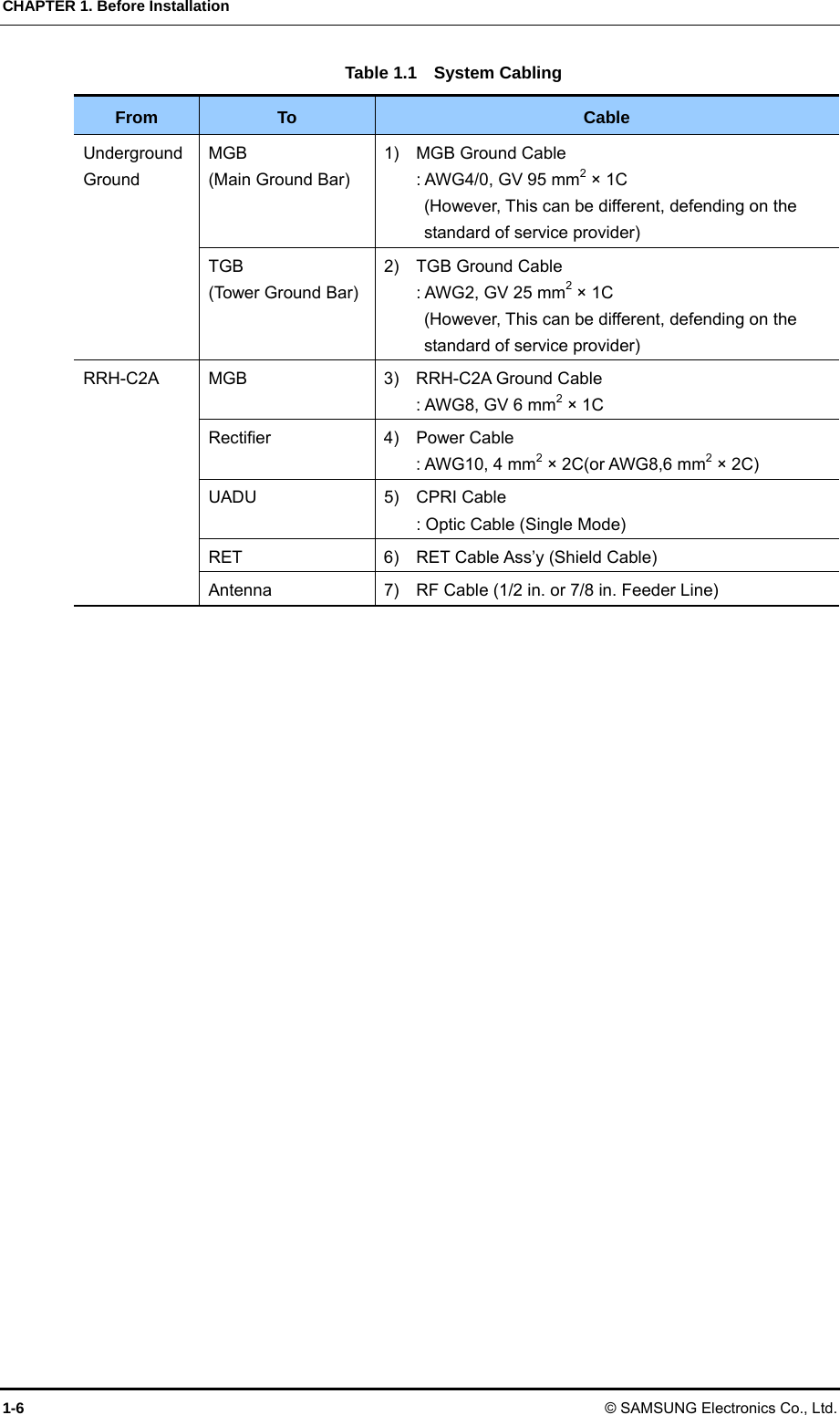
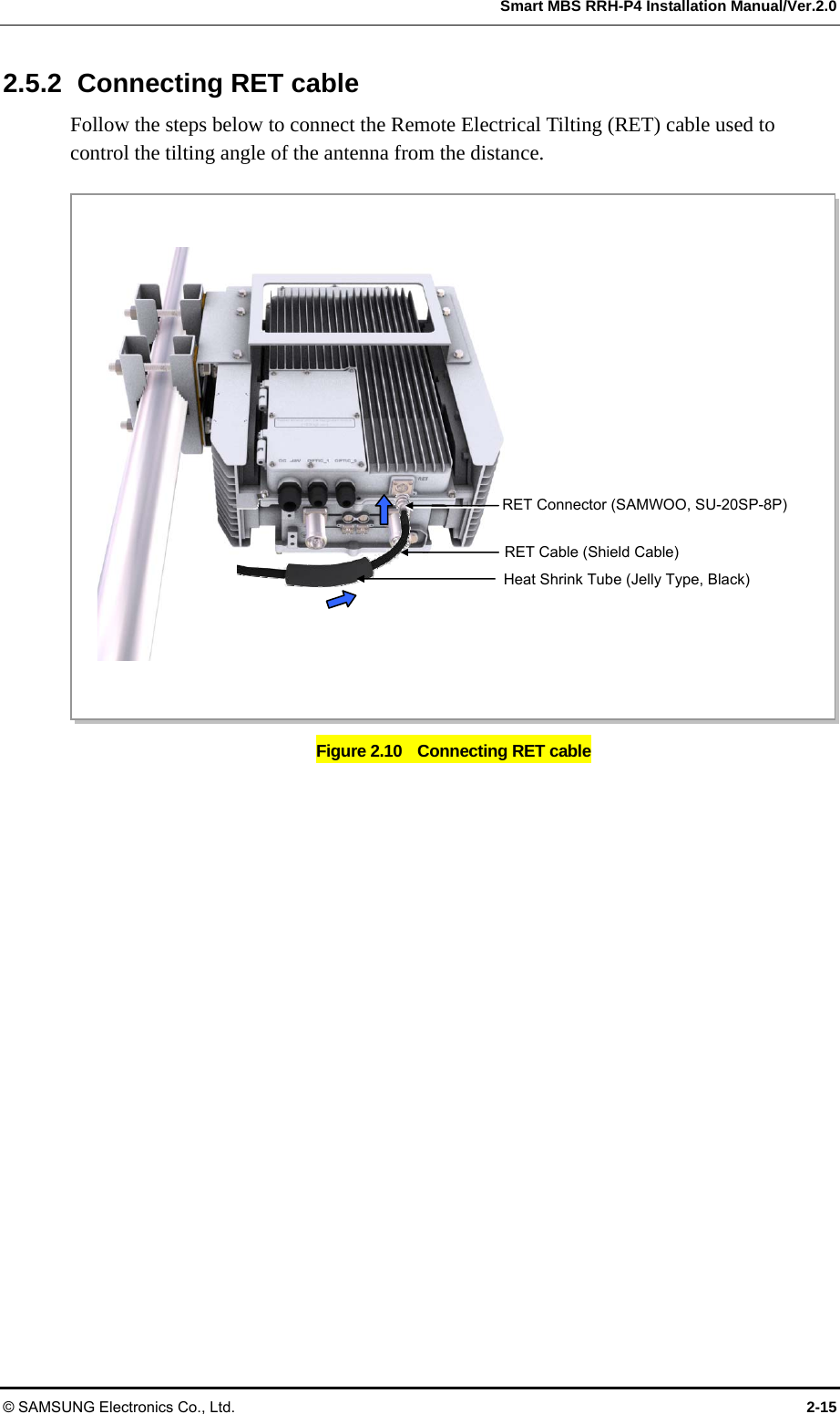
![Smart MBS RRH-P4 Installation Manual/Ver.2.0 © SAMSUNG Electronics Co., Ltd. 1-5 1.3 Cabling The following shows the cables connected to RRH-C2A. Figure 1.3 Cabling Diagram 3) RRH-C2A Ground Cable [RF Antenna] [MGB] 2) TGB Ground Cable[TGB] Feeder Line Ground Cable (Ground Kit/7/8 in. Feeder Line or more) ※ TGB and Ground Kit are used in case of the 7/8 in. feeder line or more. [Rectifier] [UADU] 1) MGB Ground Cable 5) CPRI Cable 6) RET Cable 7) RF Cable 4) Power Cable](https://usermanual.wiki/Samsung-Electronics-Co/SMM-2CR0480800.User-manual/User-Guide-1578505-Page-23.png)
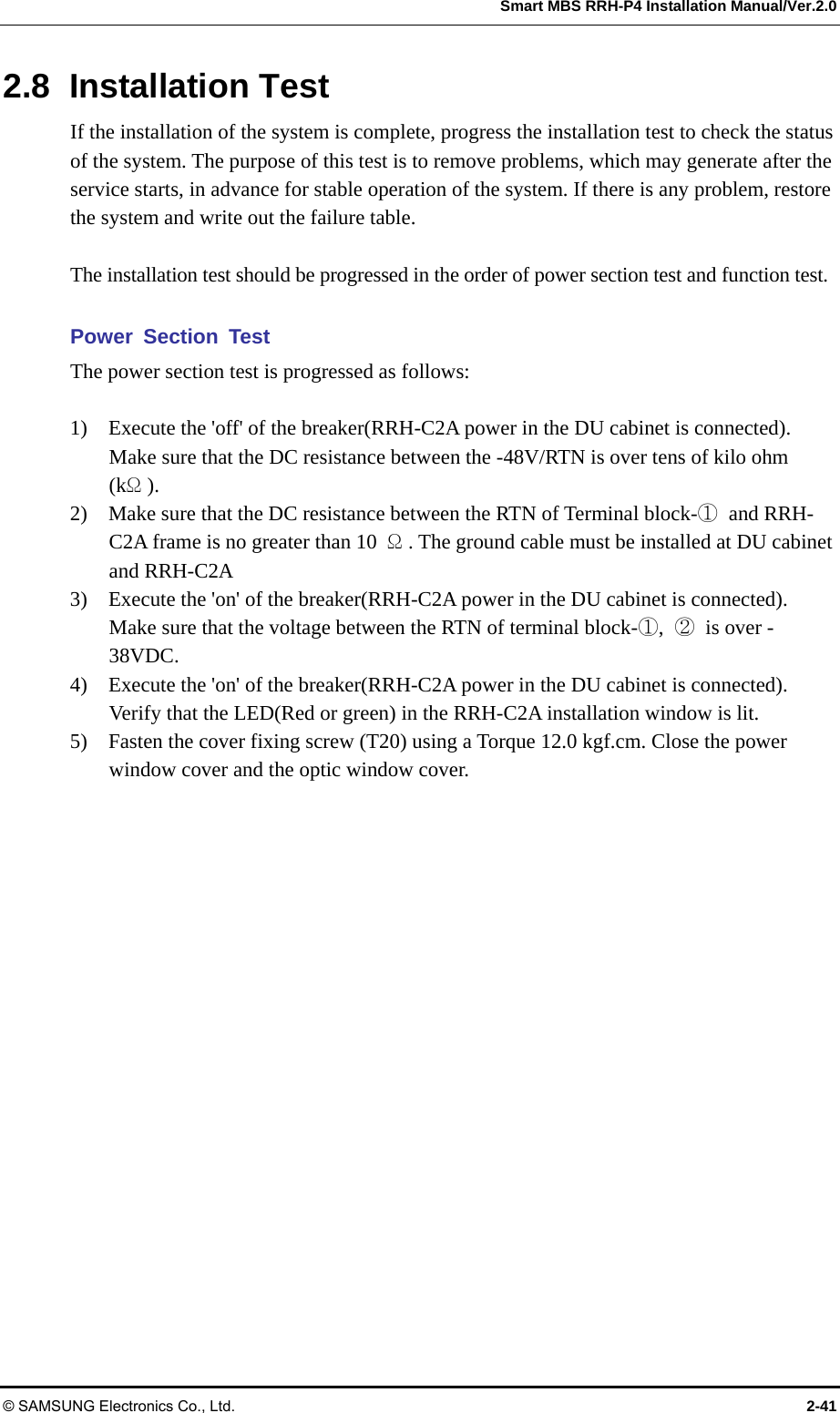
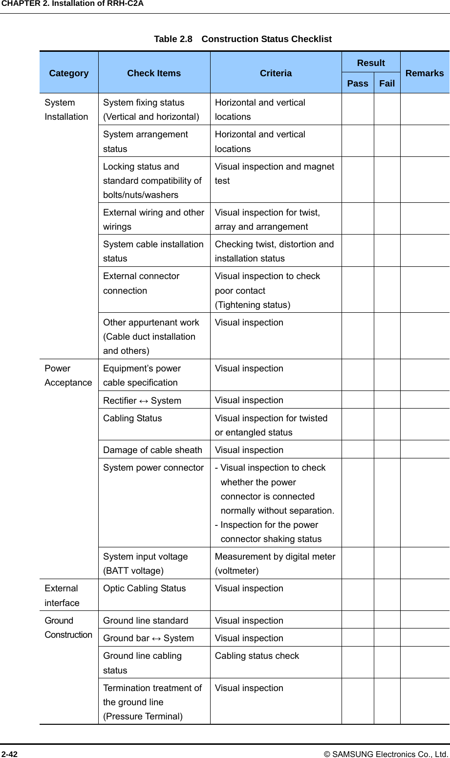
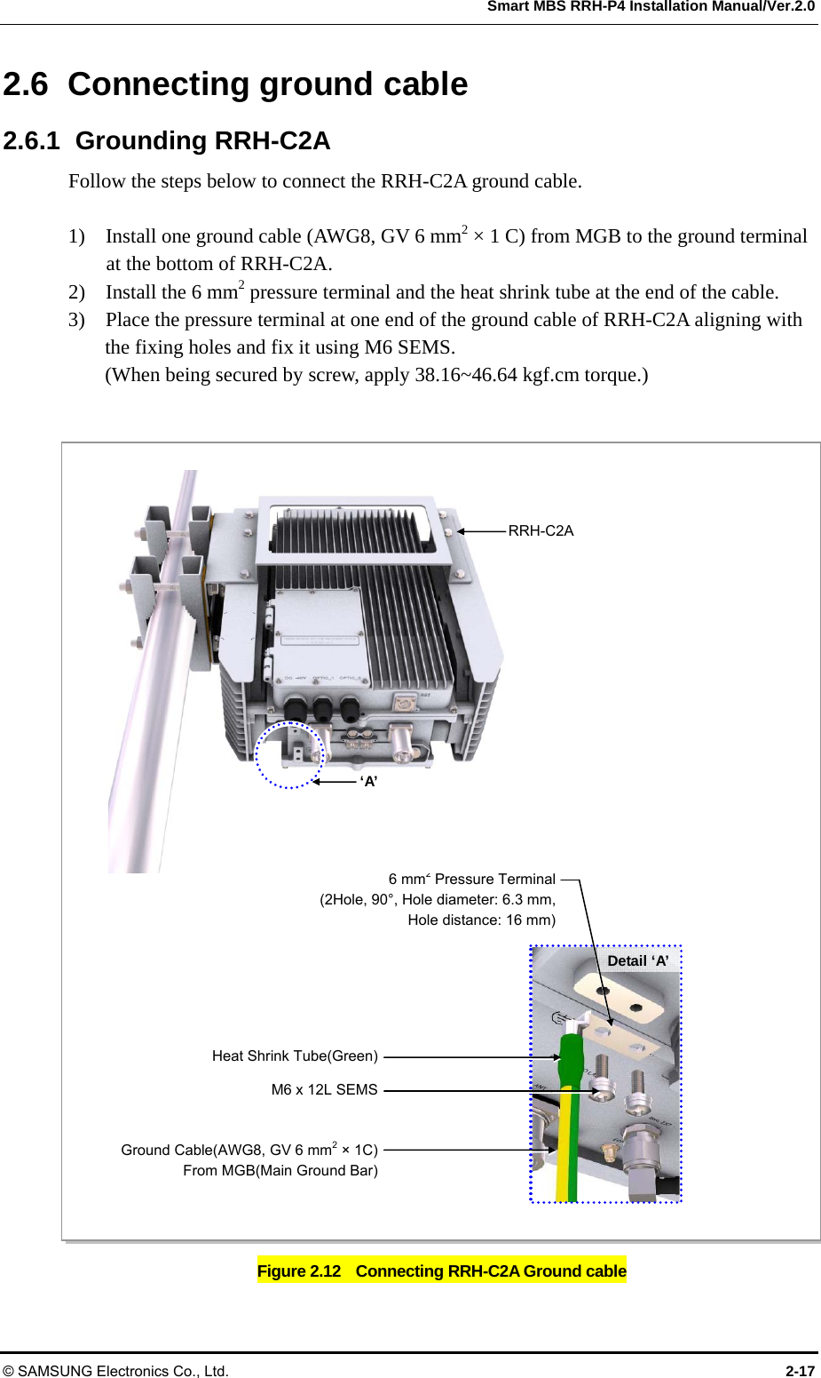
![CHAPTER 2. Installation of RRH-C2A 2-2 © SAMSUNG Electronics Co., Ltd. 2.2 Foundation Work 2.2.1 Equipment Arrangement A minimum distance must be secured around the RRH-C2A in each direction for installation and maintenance. Table 2.1 Recommended Distances for System Arrangement Item Recommended Distances Front/Rear 800 mm or more Sides 600 mm or more Clearance between racks 60 mm (when the battery cabinet is on the left and the DU cabinet is on the right) Figure 2.2 RRH-C2A Installation Space (1 sector pole type) Equipment Installation Space The figure above illustrates the installation space using a 101.6 mm(90 A) diameter pole. The measures may differ depending on the diameter of the pole. ≒239 [Unit: mm] ≒440 598 Pole (Ф60.5~101.6 mm) ≒141.6](https://usermanual.wiki/Samsung-Electronics-Co/SMM-2CR0480800.User-manual/User-Guide-1578505-Page-34.png)
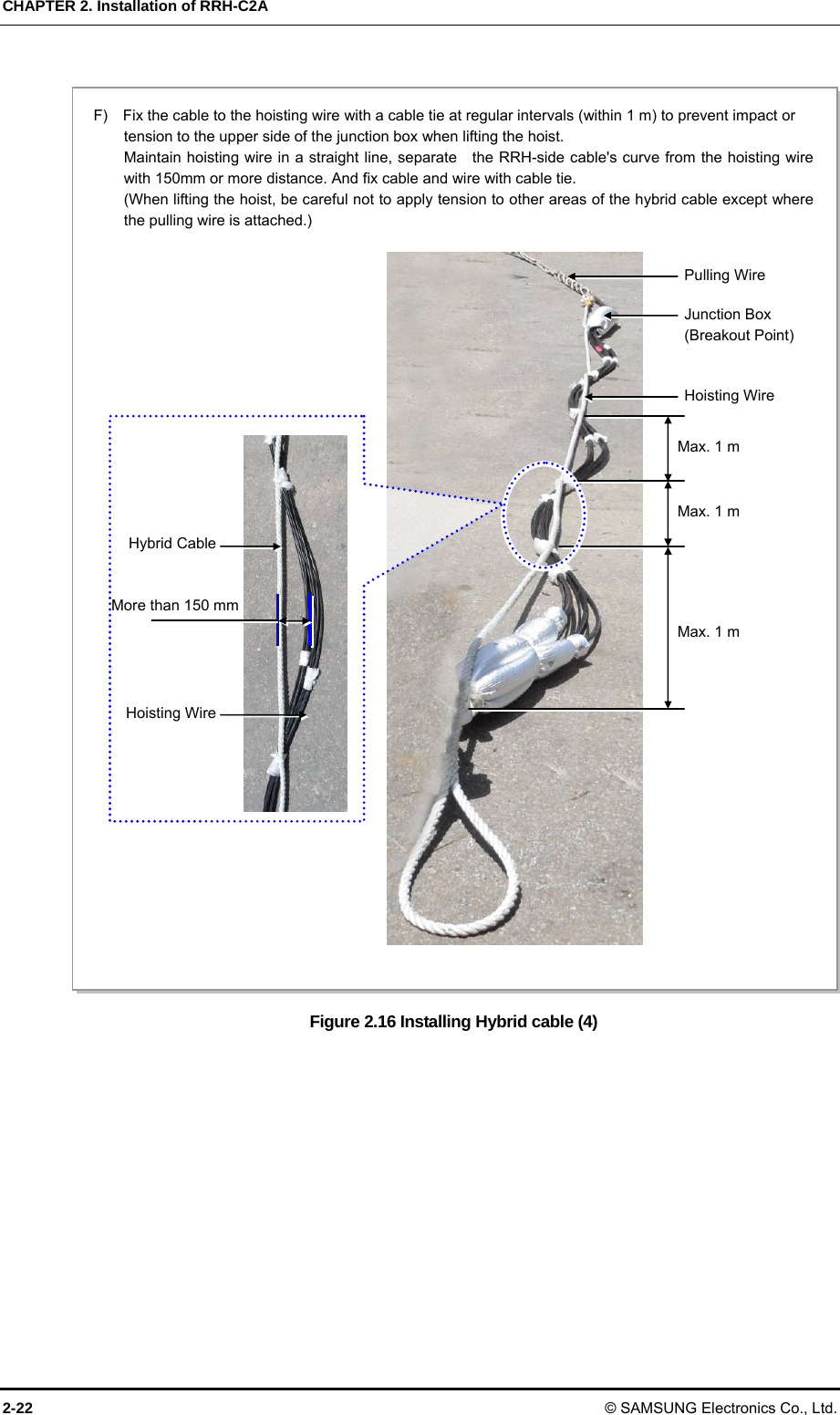
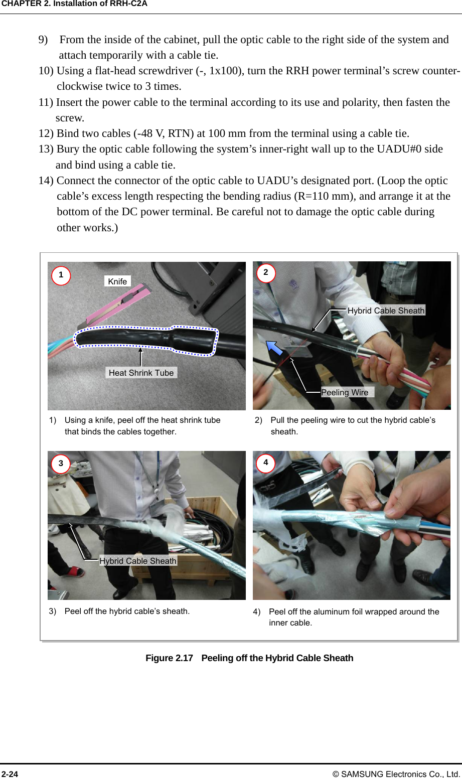
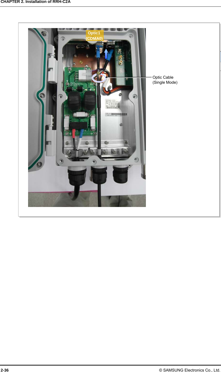
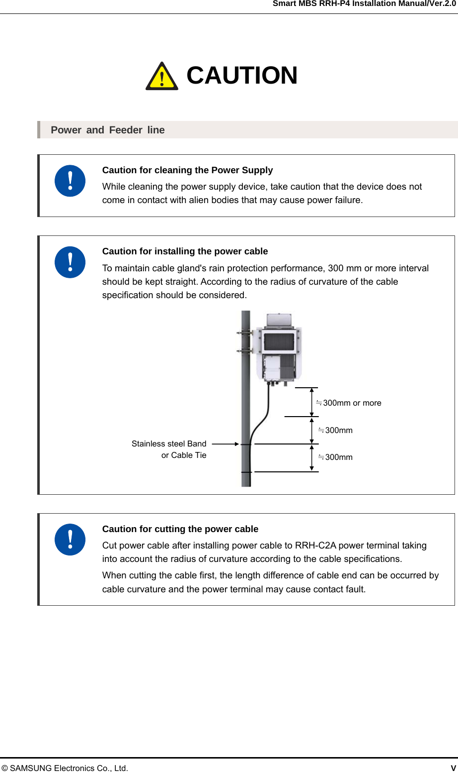
![Smart MBS RRH-P4 Installation Manual/Ver.2.0 © SAMSUNG Electronics Co., Ltd. 2-25 If the length of the hybrid cable is adequate for the installation: 1) For all power cables, leave 1000 mm from where the double-layer sheath has been peeled off and cut the excess length off. 2) Unsheathe the end of the power cable wire at 15 mm length. 3) Using a conduit, insert the hybrid cable’s power cable and optic cable together into the cabinet. Be careful not to damage the optic cable’s connector. 4) From the inside of the cabinet, pull the optic cable to the right side of the system and attach temporarily with a cable tie. 5) Using a flat-head screwdriver (-, 1x100), turn the RRH power terminal’s screw counter-clockwise 2 to 3 times. 6) Insert the power cable to the terminal according to its usage and polarity, then fasten the screw. 7) Bind two cables (-48 V, RTN) at 100 mm from the terminal using a cable tie. 8) Bury the optic cable following the system’s inner-right wall up to the UADU#0 side and bind using a cable tie. 9) Connect the connector of the optic cable to UADU’s designated port. (Loop the optic cable’s excess length respecting the bending radius (R=110 mm), and arrange it at the bottom of the DC power terminal. Be careful not to damage the optic cable during other works.) Figure 2.18 Connecting Hybrid cable (1) [Baseband Rack Right View] RRH Power TerminalDouble-layer Sheath Peel-off Point 600 mm RRH CPRI Cable(Optic Cable) Flexible Pipe (2 in.) Max. 1,000 mm Butyl Rubber TapeHybrid CableDC Power Cable](https://usermanual.wiki/Samsung-Electronics-Co/SMM-2CR0480800.User-manual/User-Guide-1578505-Page-57.png)
![Smart MBS RRH-P4 Installation Manual/Ver.2.0 © SAMSUNG Electronics Co., Ltd. 2-27 Figure 2.20 Connecting Hybrid cable (3) Figure 2.21 Connecting Hybrid cable (4) RRH_ α Power Cable Conduit#4 (Gamma) Conduit#3 (Beta) Conduit#2 (Alpha) RRH_ β Power Cable RRH_ γ Power CableRRH SPD Terminal(20 A/32 A) Space for the remainder of RRH CPRI CableRRH Interface Connector (LC/PC) RRH Interface(CPRI) Cable(Hybrid Cable)L9CA-B4T_#2 L3~5 Port [CPRI Cable Connection]](https://usermanual.wiki/Samsung-Electronics-Co/SMM-2CR0480800.User-manual/User-Guide-1578505-Page-59.png)
![CHAPTER 2. Installation of RRH-C2A 2-28 © SAMSUNG Electronics Co., Ltd. Figure 2.21 Connecting Hybrid cable (5) Managing unused port Finish unused port of UADU by dust-cap, not making the alien substance flowed. Finishing Cable Insertion Hole Finishing work is required on cable insertion holes (Cable gland, Conduit and etc.) to prevent entering of any foreign substance, external air and moisture. - Unused cable insertion hole: Finish cable insertion hole using fishing materials such as dust cap, rubber packing and etc. - Cable-installed insertion hole: After installing cable, finish insertion hole using tape, compressed sponge, rubber packing, silicon, etc. to prevent empty space. Space for the remainder of RRH CPRI CableCIMA-A L3~5 Port RRH Interface Connector(LC/PC) RRH Interface (CPRI) Cable(Hybrid Cable) [CDMA CPRI Cable Connection]](https://usermanual.wiki/Samsung-Electronics-Co/SMM-2CR0480800.User-manual/User-Guide-1578505-Page-60.png)