Samsung Electronics Co SMM-2CR0480800 Remote Radio Head User Manual
Samsung Electronics Co Ltd Remote Radio Head
Contents
- 1. User manual
- 2. user manual
User manual

Ver.
2.0
Smart MBS RRH-C2A
Installation Manual

COPYRIGHT
This manual is proprietary to SAMSUNG Electronics Co., Ltd. and is protected by copyright.
No information contained herein may be copied, translated, transcribed or duplicated for any commercial
purposes or disclosed to the third party in any form without the prior written consent of SAMSUNG Electronics
Co., Ltd.
TRADEMARKS
Product names mentioned in this manual may be trademarks and/or registered trademarks of their respective
companies.
This manual should be read and used as a guideline for properly installing and operating the product.
This manual may be changed for the system improvement, standardization and other technical reasons without prior
notice.
If you need updated manuals or have any questions concerning the contents of the manuals, contact our Document
Center at the following address or Web site:
Address: Document Center 3rd Floor Jeong-bo-tong-sin-dong. Dong-Suwon P.O. Box 105, 416, Maetan-3dong
Yeongtong-gu, Suwon-si, Gyeonggi-do, Korea 442-600
Homepage: http://www.samsungdocs.com
©2011 SAMSUNG Electronics Co., Ltd. All rights reserved.

Smart MBS RRH-P4 Installation Manual
© SAMSUNG Electronics Co., Ltd. I
INTRODUCTION
Purpose
This manual describes procedure and method for installing Smart MBS RRH-C2A.
Document Content and Organization
This manual consists of 2 Chapters, 6 Annex and Abbreviation as follows:
CHAPTER 1. Before Installation
This chapter introduces safety rules that must be understood for installing RRH-C2A and
describes the configuration of RRH-C2A.
CHAPTER 2. Installation of RRH-C2A
This chapter describes the procedure to install RRH-C2A.
ANNEX A. Sector Antenna Installation
This annex describes sector antenna configurations and its installation requirements.
ANNEX B. Feeder Line Work
This annex describes cautions and allowed radius of curvature when installing feeder line.
ANNEX C. Assembling connector
This annex describes the procedure of assembling connector.
ANNEX D. Cleaning Optic Connector
This annex describes the procedure of cleaning the optic connector and cleaning tool.
ANNEX E. Pressure Terminal Assembly
This annex describes the procedure of assembling the pressure terminal.
ANNEX F. Standard Torque
This annex describes the standard torque when assembling the fixing materials.
INTRODUCTION
II © SAMSUNG Electronics Co., Ltd.
ABBREVIATION
Describes the acronyms used in this manual.
Conventions
The following types of paragraphs contain special information that must be carefully read
and thoroughly understood. Such information may or may not be enclosed in a rectangular
box, separating it from the main text, but is always preceded by an icon and/or a bold title.
WARNING
Provides information or instructions that the reader should follow in order to avoid
personal injury or fatality.
CAUTION
Provides information or instructions that the reader should follow in order to avoid
a service failure or damage to the system.
CHECKPOINT
Provides the operator with checkpoints for stable system operation.
NOTE
Indicates additional information as a reference.
Revision History
EDITION DATE OF ISSUE REMARKS
1.0 10. 2011. First Edition
Smart MBS RRH-P4 Installation Manual
© SAMSUNG Electronics Co., Ltd. III
SAFETY CONCERNS
The purpose of the Safety Concerns section is to ensure the safety of users and prevent
property damage. Please read this document carefully for proper use.
Symbols
Caution
Indication of a general caution
Restriction
Indication for prohibiting an action for a product
Instruction
Indication for commanding a specifically required action
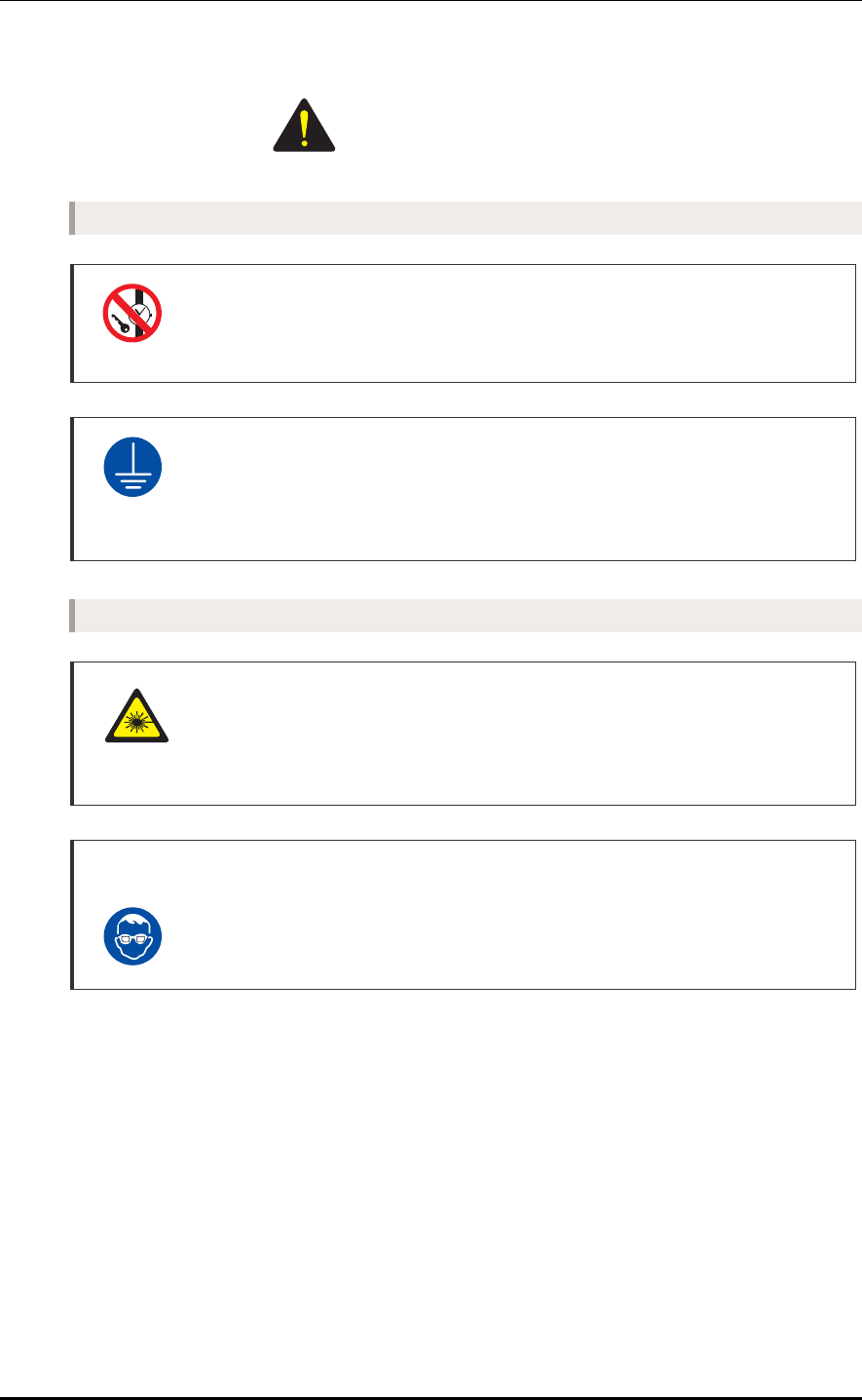
TABLE OF CONTENTS
IV © SAMSUNG Electronics Co., Ltd.
Warning
Power and Grounding
Watches, Rings, and Other Metallic Accessories
Do not wear accessories such as watches and rings in order to prevent electrical
shock.
Connecting Ground Cable
In cabling, the connection of cables without the connection to the ground cable
may cause the damage of the equipment or the bodily injury of the worker.
Connect the ground cable first.
Installation General
Caution for Laser Beam of Optical Module and Cable
The optical module and cable used in the system emit bright laser beams.
Always handle them with care as there is risk of serious injury if the eyes are
exposed to the laser beam of the optical cable.
Wearing protection gloves and goggles
Make sure to wear protection gloves and goggles to prevent damages from debris
while drilling holes in a wall or ceiling.
WARNING
Smart MBS RRH-P4 Installation Manual/Ver.2.0
© SAMSUNG Electronics Co., Ltd. V
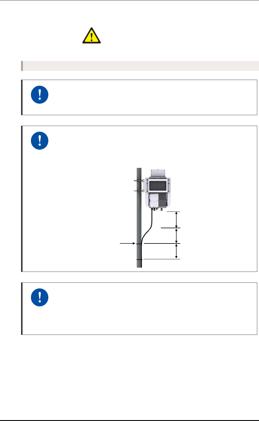
Power and Feeder line
Caution for cleaning the Power Supply
While cleaning the power supply device, take caution that the device does not
come in contact with alien bodies that may cause power failure.
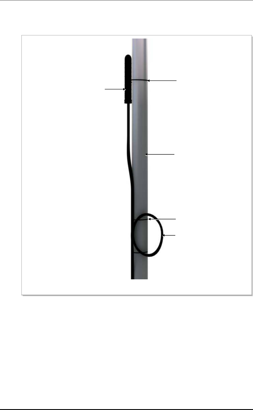
Caution for installing the power cable
To maintain cable gland's rain protection performance, 300 mm or more interval
should be kept straight. According to the radius of curvature of the cable
specification should be considered.
Caution for cutting the power cable
Cut power cable after installing power cable to RRH-C2A power terminal taking
into account the radius of curvature according to the cable specifications.
When cutting the cable first, the length difference of cable end can be occurred by
cable curvature and the power terminal may cause contact fault.
CAUTION
Stainless steel Band
or Cable Tie
≒300mm or more
≒300mm
≒300mm
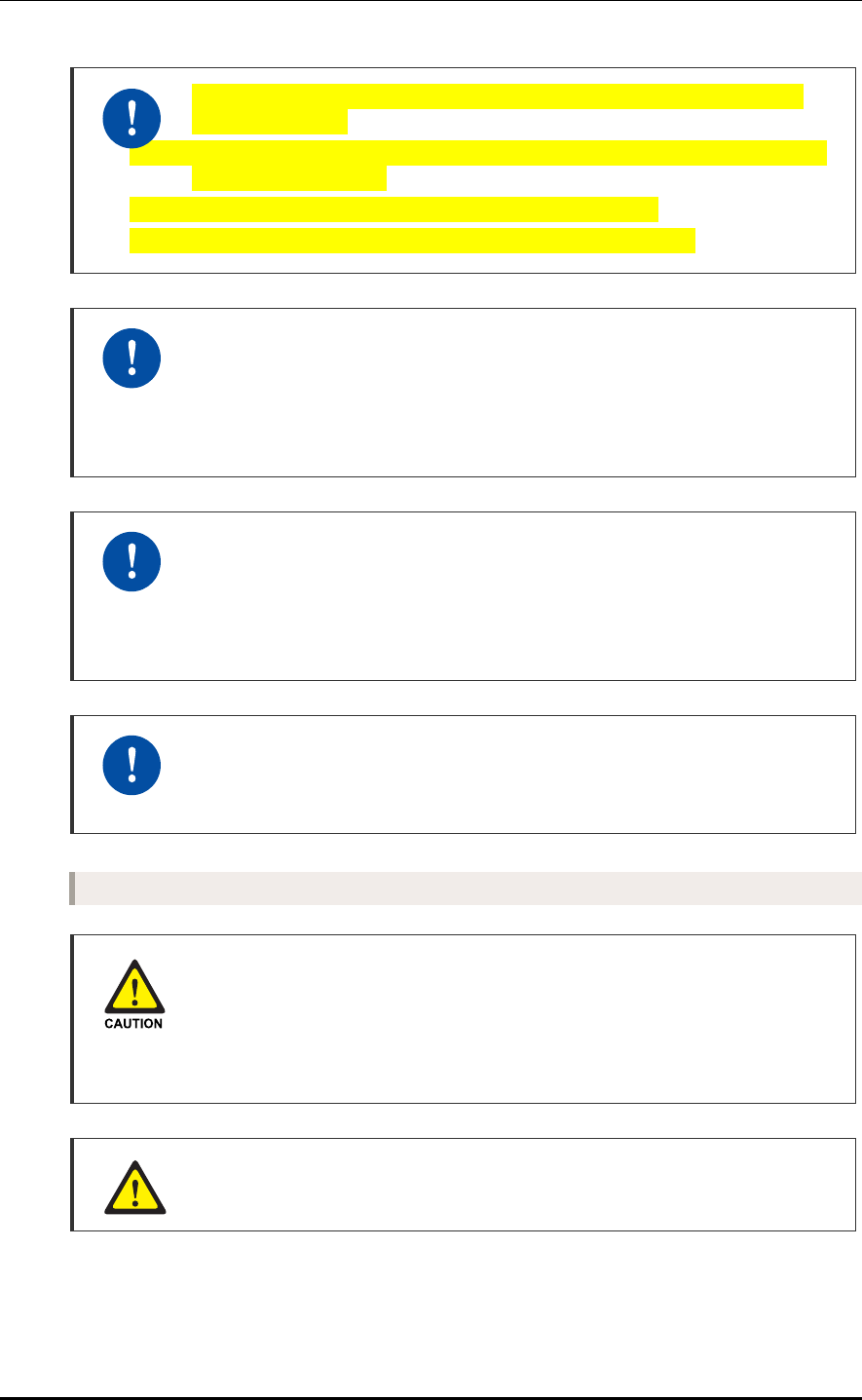
TABLE OF CONTENTS
VI © SAMSUNG Electronics Co., Ltd.
Caution for connecting power cable to power tap (‘2.7.3 Connecting RRH-
C2A Power Cable’)
- Before connecting power cable to the power tap, connect the appropriate ring lugs
to the power cable ends.
- Insert wire of power cable to ring lug head more than 10mm.
- After inserting power cable, fasten the screw by torque 11 kgf.cm.
Caution When Connecting Optical Cables
Before connecting an optical cable, make sure that there is no dust or foreign
substance on the cross-section of the connector core. If there is any dust or foreign
substance, do not remove it by blowing with your mouth. Remove the dust or
foreign substance by referring to the method of cleaning optic connector.
Radius of Curvature of Feeder Line
When installing a feeder line, the radius of curvature of the sections where cables
bent should be larger than the allowed radius of curvature. If the radius of curvature
for the feeder line installation is less than the allowed radius of curvature, it may
affect the performance of the system.
Connection of Feeder Cable Connector
Connecting the feeder cable connector is critical process, so the qualified workers
who finished the related education should perform.
Installation General
Caution when losing External Power Cable Support Bracket(‘2.6 Connecting
ground cable’)
External Power Cable Support Bracket and two cable tie (stainless steel) for
fixing cable are enclosed in RRH-C2A package. Be careful not to lose when
unpacking package.
Managing unused port
Finish unused port of UADU by dust-cap, not making the alien substance flowed.
Smart MBS RRH-P4 Installation Manual/Ver.2.0
© SAMSUNG Electronics Co., Ltd. VII
Finishing Cable Insertion Hole
Finishing work is required on cable insertion holes (Cable gland, Conduit and
etc.) to prevent entering of any foreign substance, external air and moisture.
- Unused cable insertion hole: Finish cable insertion hole using fishing materials
such as dust cap, rubber packing and etc.
- Cable-installed insertion hole: After installing cable, finish insertion hole using tape,
compressed sponge, rubber packing, silicon, etc. to prevent empty space.
Do not work by yourself
Do not work by yourself in any key process.
Caution for cleaning the Rack
Make sure that worker does not damage installed cables while cleaning the rack.
Cautions When Connecting the CRPI Cable
Failure to observe the CPRI cable connection specified in Table 2.5 may impair
the communication between the CDMA terminal.
RRH-C2A optic cable connection standard
Cable connection standard between UADU CPRI port and RRH-C2A optic port is
different according to the count(One or two) of CDMA UADU(Installed in DU
cabinet).
Connect the optic cable(Refer to the connection standard of 'table 2.6' and 'table
2.7'). Because false connection can cause the fault of call connection, be
cautious.
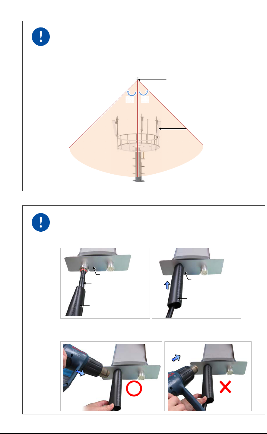
TABLE OF CONTENTS
VIII © SAMSUNG Electronics Co., Ltd.
Caution when Installing the RF antenna
To protect from lightning, the RF antenna must be installed within the shielding
angle as shown below, considering the downward distance and the angle from
the tower lightning rod or the antenna pole lightning rod.
- The protection angle of the lightning rod should be 45 degrees.
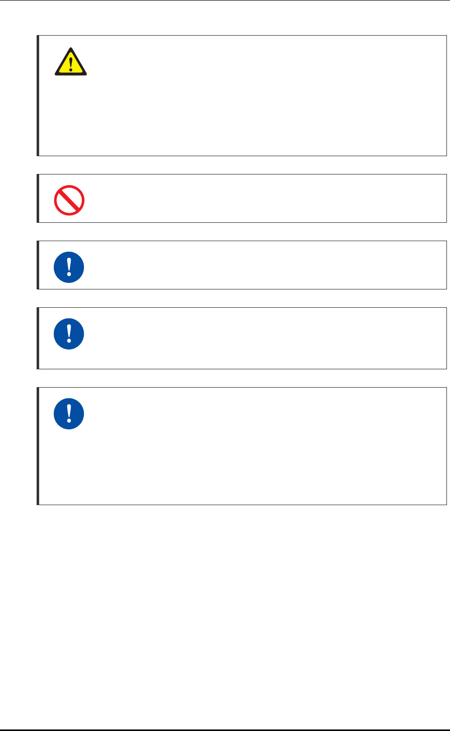
Finishing Heat Shrink Tube of a Sector Antenna
1) Insert an antenna protection plate.
2) Place the heat shrink tube on the connection point and shrink the heat shrink
tube using a heat gun.
3) Avoid aiming the heating gun toward the antenna’s body as shown in the figure
below.
Lightning rod
45°45°
RF Antenna
Heat Shrink Tube
(Jelly Type)
A
ntenna Jumper Cable
(1/2 in. Feeder Line)
Heat Shrink Tube
(Jelly Type)
A
ntenna Protection Plate
A
ntenna Protection Plate

Smart MBS RRH-P4 Installation Manual/Ver.2.0
© SAMSUNG Electronics Co., Ltd. IX
California USA Only
This Perchlorate warning applies only to primary CR (Manganese Dioxide)
Lithium coin cells in the product sold or distributed ONLY in California USA
‘Perchlorate Material-special handling may apply, See
www.dtsc.ca.gov/hazardouswaste/perchlorate.’
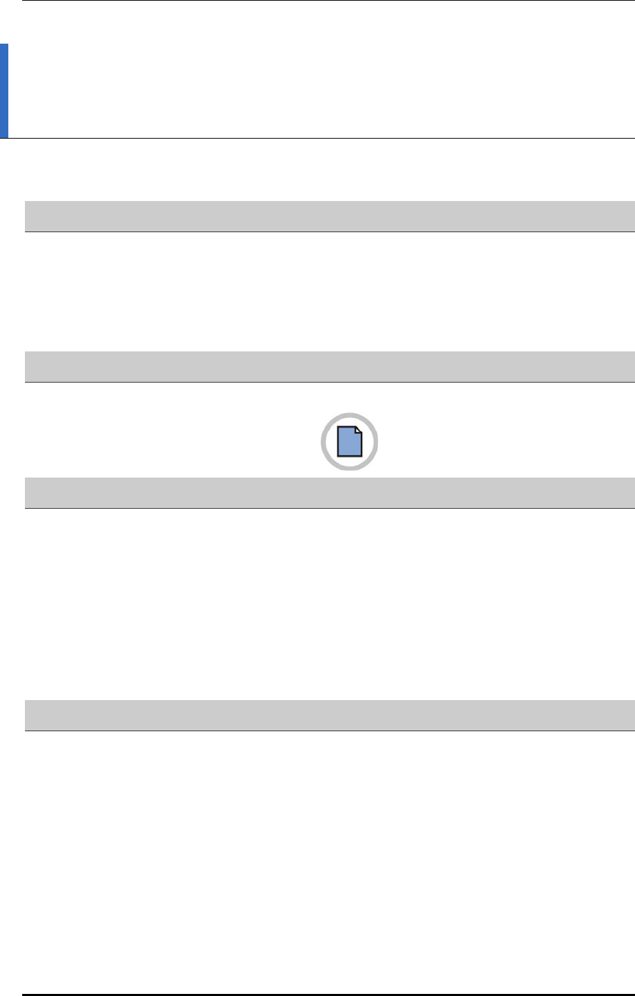
TABLE OF CONTENTS
X © SAMSUNG Electronics Co., Ltd.
TABLE OF CONTENTS
INTRODUCTION I
Purpose .................................................................................................................................................. I
Document Content and Organization ..................................................................................................... I
Conventions ........................................................................................................................................... II
Revision History ..................................................................................................................................... II
SAFETY CONCERNS III
Symbols ................................................................................................................................................ III
Warning ................................................................................................................................................ IV
California USA Only ............................................................................................................................ VIII
CHAPTER 1. Before Installation 1-1
1.1 System Configuration ............................................................................................................ 1-1
1.2 Specifications ......................................................................................................................... 1-3
1.3 Cabling .................................................................................................................................... 1-5
1.4 Installation Precaution ........................................................................................................... 1-7
1.5 Pre-Construction Inspection ............................................................................................... 1-12
1.6 Installation Tool .................................................................................................................... 1-13
CHAPTER 2. Installation of RRH-C2A 2-1
2.1 Installation Procedure ............................................................................................................ 2-1
2.2 Foundation Work .................................................................................................................... 2-2
2.2.1 Equipment Arrangement ....................................................................................................... 2-2
2.3 Unpacking and Transporting ................................................................................................. 2-3
2.3.1 Importing Items ..................................................................................................................... 2-3
2.3.2 Unpacking Items ................................................................................................................... 2-3
2.4 Fixing the System ................................................................................................................... 2-4
2.4.1 Fixing Wall Mount ................................................................................................................ 2-4
2.4.2 Fixing 1 Sector Pole ........................................................................................................... 2-7
This page is intentionally left blank.

Smart MBS RRH-P4 Installation Manual/Ver.2.0
© SAMSUNG Electronics Co., Ltd. XI
2.5 Connecting cable between RRH and Antenna .............................................................. 2-10
2.5.1 Connecting Feeder Line .................................................................................................... 2-10
2.5.2 Connecting RET cable ........................................................................................................ 2-15
2.6 Connecting ground cable .................................................................................................. 2-17
2.6.1 Grounding RRH-C2A .......................................................................................................... 2-17
2.7 Connecting Hybrid cable ..................................................................................................... 2-19
2.7.1 Installing Hybrid cable ......................................................................................................... 2-19
2.7.2 Connecting DU Cabinet side cable .................................................................................... 2-23
2.7.3 Connecting RRH-C2A Power Cable .................................................................................. 2-29
2.7.4 Connecting RRH-C2A CPRI cable ..................................................................................... 2-34
2.7.5 Remaining length of Hybrid cable ...................................................................................... 2-38
2.8 Installation Test .................................................................................................................... 2-41
ANNEX A. Sector Antenna Installation A-1
A.1 Cautions when Installing a Sector Antenna ........................................................................ A-1
A.2 Sector Antenna Layout .......................................................................................................... A-1
A.3 Sector Antenna Installation ................................................................................................... A-2
ANNEX B. Feeder Line Work 오류! 책갈피 가 정의 되어 있지 않습 니 다.
B.1 When installing the feeder, the cautions ................ 오류! 책갈피가 정의되어 있지 않습니다.
B.2 Antenna Feeder Cable Ground ................................ 오류! 책갈피가 정의되어 있지 않습니다.
B.3 Tower Ground Construction .................................... 오류! 책갈피가 정의되어 있지 않습니다.
ANNEX C. Assembling connector 오류! 책갈피 가 정의 되 어 있지 않습 니 다.
C.1 RJ-45 (Shield type) ................................................... 오류! 책갈피가 정의되어 있지 않습니다.
C.2 RJ-45 (Normal type) .................................................. 오류! 책갈피가 정의되어 있지 않습니다.
C.3 N type-male (LMR-400) ............................................. 오류! 책갈피가 정의되어 있지 않습니다.
C.4 TNC-male (LMR-400) ................................................. 오류! 책갈피가 정의되어 있지 않습니다.
C.5 N type-male (1/2 in. feeder line) ............................... 오류! 책갈피가 정의되어 있지 않습니다.
C.6 Din type-male (1/2 in. Feeder Line) .......................... 오류! 책갈피가 정의되어 있지 않습니다.
C.7 Finishing connector connection with the tape ....... 오류! 책갈피가 정의되어 있지 않습니다.
C.8 How to Shrink the Heat Shrink Tube ....................... 오류! 책갈피가 정의되어 있지 않습니다.
C.8.1 When assembling a connector to the feeder line .... 오류! 책갈피가 정의되어 있지 않습니다.
C.8.2 When connecting a connector to another connector오류! 책갈피가 정의되어 있지 않습니다.

TABLE OF CONTENTS
XII © SAMSUNG Electronics Co., Ltd.
ANNEX D. Cleaning Optic Connector 오류! 책갈피 가 정의 되 어 있지 않습 니 다.
D.1 Cleaning Optic Connector ........................................ 오류! 책갈피가 정의되어 있지 않습니다.
D.2 IBCTM Brand Cleaner ................................................. 오류! 책갈피가 정의되어 있지 않습니다.
D.2.1 IBCTM brand type cleaner (P/N 9393) ......................오류! 책갈피가 정의되어 있지 않습니다.
ANNEX E. Pressure Terminal Assembly 오류! 책갈피 가 정의 되 어 있지 않습 니 다.
ANNEX F. Standard Torque 오류! 책갈피 가 정의 되 어 있지 않습 니 다.
ABBREVIATION 오류! 책갈피 가 정의되 어 있지 않습 니 다.
C ~ U .....................................................................................오류! 책갈피가 정의되어 있지 않습니다.
LIST OF FIGURES
Figure 1.1 RRH-C2A Configuration ......................................................................................... 1-1
Figure 1.2 External Interfaces of RRH-C2A ............................................................................ 1-2
Figure 1.3 Cabling Diagram .................................................................................................... 1-5
Figure 2.1 System Installation & Cable Connection Procedure ............................................... 2-1
Figure 2.2 RRH-C2A Installation Space (1 sector pole type) ................................................... 2-2
Figure 2.3 Fixing Wall Mount (1) ............................................................................................. 2-4
Figure 2.4 Fixing Wall Mount (2) ............................................................................................. 2-5
Figure 2.5 Fixing 1 sector pole (1) .............................. 오류! 책갈피가 정의되어 있지 않습니다.
Figure 2.6 Fixing 1 sector pole (2) .............................. 오류! 책갈피가 정의되어 있지 않습니다.
Figure 2.7 RRH-C2A Feeder Line Connection Diagram ....................................................... 2-10
Figure 2.8 Connecting RRH-C2A Feeder Line (1) ................................................................. 2-11
Figure 2.9 Connecting RRH-C2A Feeder Line (2) ................................................................. 2-12
Figure 2.10 Connecting RET cable ....................................................................................... 2-15
Figure 2.11 RET Cable connector ......................................................................................... 2-16
Figure 2.12 Connecting RRH-C2A Ground cable .................................................................. 2-17
Figure 2.13 Installing Hybrid cable (1)................................................................................... 2-19
Figure 2.14 Installing Hybrid cable (2)................................................................................... 2-20
Figure 2.15 Installing Hybrid cable (3)................................................................................... 2-21
Figure 2.16 Installing Hybrid cable (4) ..................................................................................... 2-22
Figure 2.17 Peeling off the Hybrid Cable Sheath .................................................................. 2-24
Figure 2.18 Connecting Hybrid cable (1) .............................................................................. 2-25
Figure 2.19 Connecting Hybrid cable (2) .............................................................................. 2-26

Smart MBS RRH-P4 Installation Manual/Ver.2.0
© SAMSUNG Electronics Co., Ltd. XIII
Figure 2.20 Connecting Hybrid cable (3) .............................................................................. 2-27
Figure 2.21 Connecting Hybrid cable (4) .............................................................................. 2-27
Figure 2.22 Connecting RRH-C2A power cable (AWG8) (1) ................................................ 2-29
Figure 2.23 Connecting RRH-C2A power cable (AWG8) (2) ....... 오류! 책갈피가 정의되어 있지
않습니다.
Figure 2.24 Connecting RRH-C2A power cable (AWG8) (3) ................................................ 2-30
Figure 2.25 Connecting RRH-C2A power cable (AWG8) (4) ................................................ 2-32
Figure 2.26 Connecting RRH-C2A power cable (AWG8) (5) ....... 오류! 책갈피가 정의되어 있지
않습니다.
Figure 2.27 Connecting RRH-C2A power cable (AWG8) (6) ....... 오류! 책갈피가 정의되어 있지
않습니다.
Figure 2.28 Connecting RRH-C2A power cable (AWG10) (1) ..... 오류! 책갈피가 정의되어 있지
않습니다.
Figure 2.29 Connecting RRH-C2A power cable (AWG10) (2) ..... 오류! 책갈피가 정의되어 있지
않습니다.
Figure 2.30 Connecting RRH-C2A power cable (AWG10) (3) ..... 오류! 책갈피가 정의되어 있지
않습니다.
Figure 2.31 Connecting RRH-C2A power cable (AWG10) (4) ..... 오류! 책갈피가 정의되어 있지
않습니다.
Figure 2.32 Connecting RRH-C2A power cable (AWG10) (5) ..... 오류! 책갈피가 정의되어 있지
않습니다.
Figure 2.33 Connecting RRH-C2A power cable (AWG10) (6) ..... 오류! 책갈피가 정의되어 있지
않습니다.
Figure 2.34 Connecting RRH-C2A CPRI cable (1) ............................................................... 2-34
Figure 2.35 Connecting RRH-C2A CPRI cable (2) ............................................................... 2-36
Figure 2.36 Remaining length of Hybrid cable (1) ................................................................ 2-38
Figure 2.37 Remaining length of Hybrid cable (2) ................................................................ 2-39
Figure 2.38 Remaining length of Hybrid cable (3) ................................................................ 2-40
Figure 2.39 RRH-C2A Power Section Test ................. 오류! 책갈피가 정의되어 있지 않습니다.
Figure A.1 Sector Antenna ..................................................................................................... A-2
Figure B.1 Feeder Cable Grounding (1) ..................... 오류! 책갈피가 정의되어 있지 않습니다.
Figure B.2 Feeder Cable Grounding (2) ..................... 오류! 책갈피가 정의되어 있지 않습니다.
Figure B.3 Feeder Cable Grounding (3) ..................... 오류! 책갈피가 정의되어 있지 않습니다.
Figure B.4 Feeder Cable Grounding (4) ..................... 오류! 책갈피가 정의되어 있지 않습니다.
Figure B.5 Connecting the Tower Ground Cable ........ 오류! 책갈피가 정의되어 있지 않습니다.
Figure C.1 Assembling the RJ-45 connector (Shield type) .......... 오류! 책갈피가 정의되어 있지
않습니다.

TABLE OF CONTENTS
XIV © SAMSUNG Electronics Co., Ltd.
Figure C.2 Assembling the RJ-45 connector (Normal type) ........ 오류! 책갈피가 정의되어 있지
않습니다.
Figure C.3 Assembling the N type-male connector (LMR-400) (1)오류! 책갈피가 정의되어 있지
않습니다.
Figure C.4 Assembling the N type-male connector (LMR-400) (2)오류! 책갈피가 정의되어 있지
않습니다.
Figure C.5 Assembling the TNC-male connector (1) .. 오류! 책갈피가 정의되어 있지 않습니다.
Figure C.6 Assembling the TNC-male connector (2) .. 오류! 책갈피가 정의되어 있지 않습니다.
Figure C.7 Assembling the N type-male Connector (1/2 in. Feeder Line) (1)....... 오류! 책갈피가
정의되어 있지 않습니다.
Figure C.8 Assembling the N type-male Connector (1/2 in. Feeder Line) (2)....... 오류! 책갈피가
정의되어 있지 않습니다.
Figure C.9 Assembling the N type-male Connector (1/2 in. Feeder Line) (3)....... 오류! 책갈피가
정의되어 있지 않습니다.
Figure C.10 Assembling the N type-male Connector (1/2 in. Feeder Line) (4)..... 오류! 책갈피가
정의되어 있지 않습니다.
Figure C.11 Assembling the Din type-male Connector (1/2 in. Feeder Line) (1) .. 오류! 책갈피가
정의되어 있지 않습니다.
Figure C.12 Assembling the Din type-male Connector (1/2 in. Feeder Line) (2) .. 오류! 책갈피가
정의되어 있지 않습니다.
Figure C.13 Finishing connector connection with the tape .......... 오류! 책갈피가 정의되어 있지
않습니다.
Figure C.14 Shrinking the Heat Shrink Tube-Feeder line (1) ...... 오류! 책갈피가 정의되어 있지
않습니다.
Figure C.15 Shrinking the Heat Shrink Tube-Feeder line (2) ...... 오류! 책갈피가 정의되어 있지
않습니다.
Figure C.16 Shrinking the Heat Shrink Tube-Connector (1) ........ 오류! 책갈피가 정의되어 있지
않습니다.
Figure C.17 Shrinking the Heat Shrink Tube-Connector (2) ........ 오류! 책갈피가 정의되어 있지
않습니다.
Figure C.18 Shrinking the Heat Shrink Tube-Connector (3) ........ 오류! 책갈피가 정의되어 있지
않습니다.
Figure D.1 Optic Connector Cleaner (IBCTM Brand Type Cleaner: P/N 9393) .... 오류! 책갈피가
정의되어 있지 않습니다.
Figure D.2 Optic Module Cleaning (LC type Jack) ...... 오류! 책갈피가 정의되어 있지 않습니다.
Figure D.3 Optic Cable Connector Cleaning (LC type plug) ....... 오류! 책갈피가 정의되어 있지
않습니다.
Figure D.4 Measuring the Optical Output and Connecting the Optic Connector .. 오류! 책갈피가
정의되어 있지 않습니다.

Smart MBS RRH-P4 Installation Manual/Ver.2.0
© SAMSUNG Electronics Co., Ltd. XV
Figure E.1 Pressure Terminal Assembly (1) ............... 오류! 책갈피가 정의되어 있지 않습니다.
Figure E.2 Pressure Terminal Assembly (2) ............... 오류! 책갈피가 정의되어 있지 않습니다.
LIST OF TABLES
Table 1.1 System Cabling ....................................................................................................... 1-6
Table 1.2 Allowed Cable Bend Radius ................................................................................... 1-9
Table 1.3 Basic Installation Tools .......................................................................................... 1-13
Table 2.1 Recommended Distances for System Arrangement ............................................... 2-2
Table 2.2 GPS Identification Tag of Feeder line .................................................................... 2-14
Table 2.3 RET Cable-Side Connector Pin Map .................................................................... 2-16
Table 2.4 Hybrid Cable Color Map ........................................................................................ 2-26
Table 2.5 CPRI Cable connection configuration ................................................................... 2-36
Table 2.6 CPRI cable connection standard-When CDMA DU Shelf is one .......... 오류! 책갈피가
정의되어 있지 않습니다.
Table 2.7 CPRI cable connection standard-When CDMA DU Shelf is two .......... 오류! 책갈피가
정의되어 있지 않습니다.
Table 2.8 Construction Status Checklist ............................................................................... 2-42
Table B.1 Curvature Radius of Feeder Cable for Outdoor ........... 오류! 책갈피가 정의되어 있지
않습니다.
Table B.2 Curvature Radius of Feeder Cable for Indoor오류! 책갈피가 정의되어 있지 않습니다.
Table B.3 Curvature Radius of LMR-400 (Based on Times Microwave system) .. 오류! 책갈피가
정의되어 있지 않습니다.
Table B.4 Connector Connection Torque Value .......... 오류! 책갈피가 정의되어 있지 않습니다.
Table B.5 TGB Installation Example ........................... 오류! 책갈피가 정의되어 있지 않습니다.
Table E.1 Press Size by Cable Thickness .................. 오류! 책갈피가 정의되어 있지 않습니다.
Table F.1 Standard Torque Value for Fastening Bolts . 오류! 책갈피가 정의되어 있지 않습니다.

TABLE OF CONTENTS
XVI © SAMSUNG Electronics Co., Ltd.
This page is intentionally left blank.
Smart MBS RRH-P4 Installation Manual
© SAMSUNG Electronics Co., Ltd. 1-1
CHAPTER 1. Before Installation
1.1 System Configuration
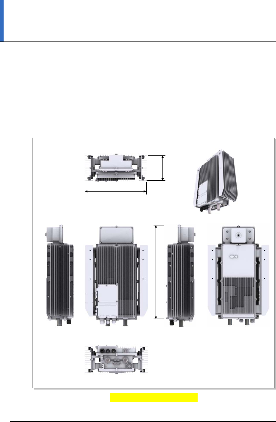
RRH-C2A Configuration
The following shows the configuration of RRH-C2A.
Figure 1.1 RRH-C2A Configuration
[Top View]
[Unit: mm]
[Front View]
[Bottom View]
[Right View] [Left View] [Rear View]
598
171
400
CHAPTER 1. Before Installation
1-2 © SAMSUNG Electronics Co., Ltd.
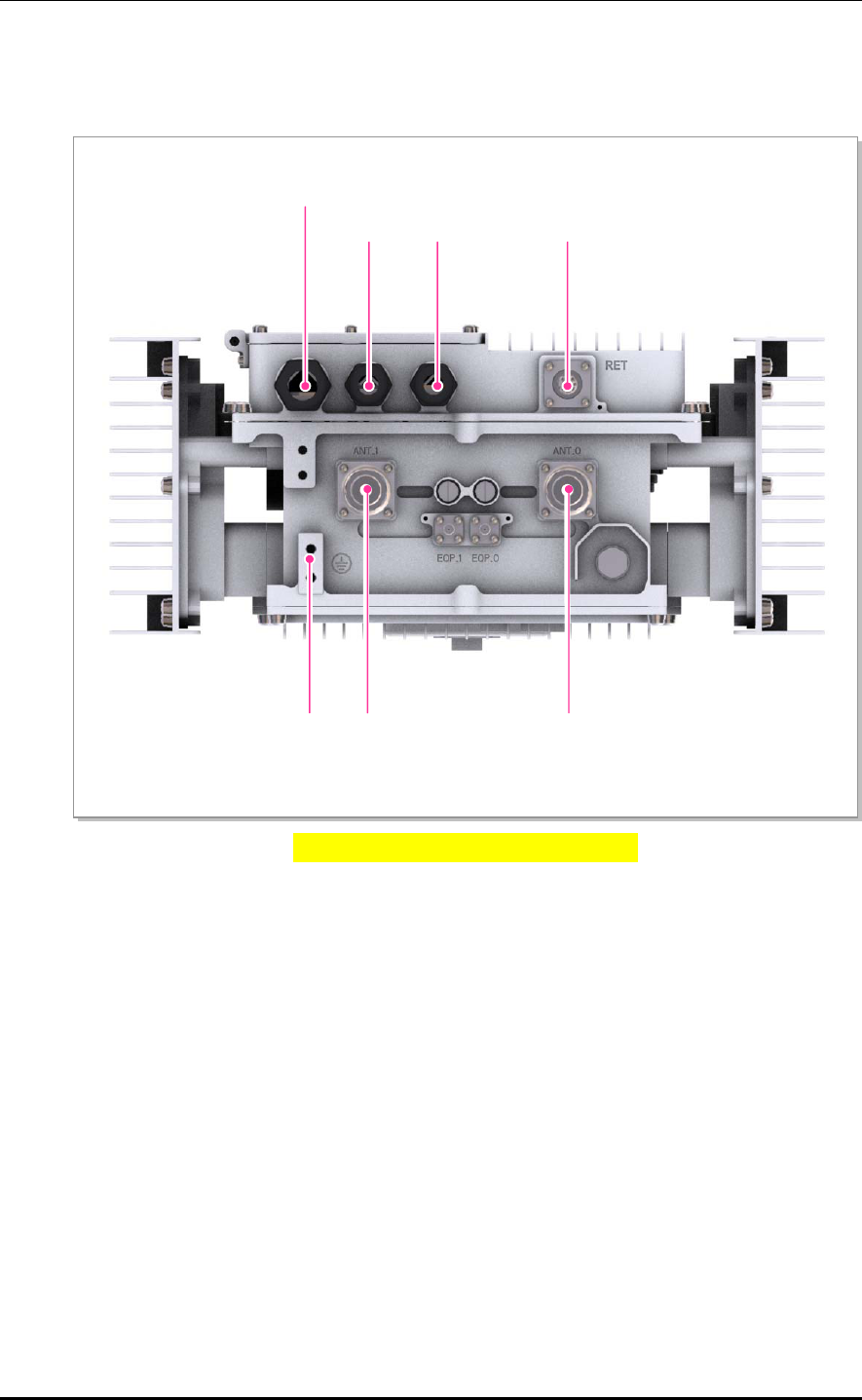
External Interfaces of RRH-C2A
The following shows the external interfaces of RRH-C2A.
Figure 1.2 External Interfaces of RRH-C2A
[Bottom View]
POWER
[-48 V]
OPTIC_1 RET
Ground ANT 0
ANT 1
OPTIC_0
Smart MBS RRH-P4 Installation Manual/Ver.2.0
© SAMSUNG Electronics Co., Ltd. 1-3
1.2 Specifications
Capacity
The following table shows the specifications for RRH-C2A.
Item Specifications
Air Standard FDD CDMA
Configuration 2T2R, with internal duplexer and external Tx filter (optional)
Operating Frequency - Tx : 862~869MHz
- Rx : 817~824MHz
Channel Bandwidth - CDMA : 1.25 MHz
Capacity - CDMA : 5 carriers
Output Power 100W total (50W+50W)
Multiple Antenna - CDMA: 1T2R/2T2R
Baseband Interface 2.4576Gbps, Single-mode, Bi-directional, ~10Km
CRPI version : 4.0 or above
Input Power
The following table shows the power specifications for RRH-C2A.
Item Specifications
Input voltage -48 VDC
Current consumption 9.5 A
Unit Size and Weight
The following table shows the size and weight of RRH-C2A.
Item Specifications
Size (mm, W × D × H) - 400 ×171 × 598 (with External Filter)
- 400 ×171 × 490 (without External Filter)
Weight (kg) - 23.5 (with External Filter)
- 21 (without External Filter)

CHAPTER 1. Before Installation
1-4 © SAMSUNG Electronics Co., Ltd.
Ambient Conditions
This section describes the operating temperature, humidity level and other ambient
conditions and related standard of RRH-C2A.
The following table shows the ambient conditions and related standard of RRH-C2A.
Item Range
Temperaturea) -40~55°C (-40~131°F) without solar load
Humiditya) 10~95%
The moisture content must not exceed 0.024 kg per 1 kg of air.
Altitude 0~1,800 m (0~6,000 ft)
Vibration GR-63-CORE Sec.4.4
Earthquake
Office Vibration
Transportation Vibration
Noise (sound pressure level) Max. 65 dBA at distance of 1.5 m (5 ft) and height of 1.0 m (3 ft)
Electromagnetic compatibility
(EMC)
FCC Title47 Part 15 Class B
US Federal Regulation FCC Title47 Part90
a) Temperature and humidity are measured at 1.5 m (59 in) above the floor and at 400 mm (15.8 in) away
from the front panel of the RRH-C2A.
Smart MBS RRH-P4 Installation Manual/Ver.2.0
© SAMSUNG Electronics Co., Ltd. 1-5
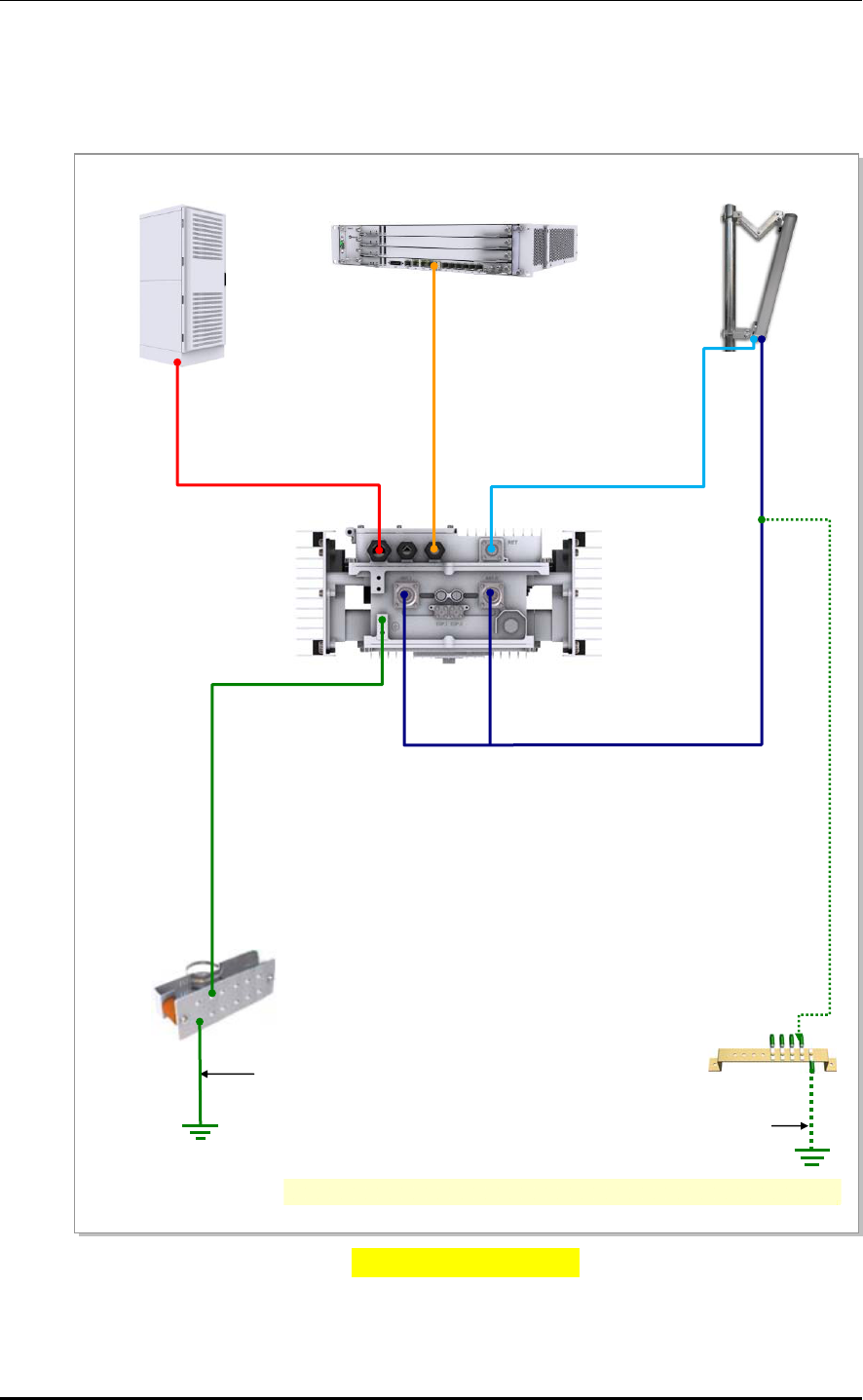
1.3 Cabling
The following shows the cables connected to RRH-C2A.
Figure 1.3 Cabling Diagram
3) RRH-C2A Ground Cable
[RF Antenna]
[MGB]
2) TGB Ground Cable
[TGB]
Feeder Line Ground Cable
(Ground Kit/7/8 in. Feeder Line or more)
※ TGB and Ground Kit are used in case of the 7/8 in. feeder line or more.
[Rectifier] [UADU]
1) MGB Ground Cable
5) CPRI Cable
6) RET Cable
7) RF Cable
4) Power Cable
CHAPTER 1. Before Installation
1-6 © SAMSUNG Electronics Co., Ltd.
Table 1.1 System Cabling
From To Cable
Underground
Ground
MGB
(Main Ground Bar)
1) MGB Ground Cable
: AWG4/0, GV 95 mm2 × 1C
(However, This can be different, defending on the
standard of service provider)
TGB
(Tower Ground Bar)
2) TGB Ground Cable
: AWG2, GV 25 mm2 × 1C
(However, This can be different, defending on the
standard of service provider)
RRH-C2A MGB 3) RRH-C2A Ground Cable
: AWG8, GV 6 mm2 × 1C
Rectifier 4) Power Cable
: AWG10, 4 mm2 × 2C(or AWG8,6 mm2 × 2C)
UADU 5) CPRI Cable
: Optic Cable (Single Mode)
RET 6) RET Cable Ass’y (Shield Cable)
Antenna 7) RF Cable (1/2 in. or 7/8 in. Feeder Line)
Smart MBS RRH-P4 Installation Manual/Ver.2.0
© SAMSUNG Electronics Co., Ltd. 1-7
1.4 Installation Precaution
The following precaution must be observed to prevent accidents during RRH-C2A
installation.
Before Installation
Install a high voltage warning sign near the area where high voltage cable is located.
Install a restricted entry warning sign near the potential accident area.
Cover exposed areas such as junctions, ceilings, footholds etc. with safety rails or
fence off the area.
Study use of the fire alarm and the location of the fire extinguisher and how to use it.
Check the location of the nearest emergency exit.
During Installation
Cut all equipment power before installation.
Always wear protection gloves and goggles when drilling holes into the wall or ceiling.
To prevent electric shocks from metallic objects, remove all accessories such as
watches or rings.
Wearing protection gloves and goggles
Make sure to wear protection gloves and goggles to prevent damages from debris
while drilling holes in a wall or ceiling.
Watches, Rings, and Other Metallic Accessories
Do not wear accessories such as watches and rings in order to prevent electrical
shock.
Do not work by yourself
Do not work by yourself in any key process.

CHAPTER 1. Before Installation
1-8 © SAMSUNG Electronics Co., Ltd.
Cable Path Inspection
When installing a cable that connects between the rectifier, Main Ground Bar (MGB), and
backhaul device, etc. within the system, the cable path length and the cable installation
method, etc. must be inspected.
Follow these guidelines when inspecting the cabling path.
A minimum cable length must be selected provided that it does not affect the cable
installation and maintenance.
The cable must be placed in a location where it will not be damaged by external
factors. (Power line, flooding, footpaths, etc.)
In areas where the cable can be damaged by external factors, ensure that measures are
taken to prevent damages to the cable. (Cable tray, ducts, flexible pipe, etc.)
Cable Cutting
Measure the exact distance, carefully checking the route, and cut the cable using a cutting tool.
Follow these guidelines when cutting the cable.
Cut the cable to the length determined in the Cable Path Inspection step.
Use a dedicated cable cutting tool.
Cut the cable at right angles.
Be careful to keep the cable away from any moisture, iron, lead, dust or other foreign
material when cutting. Remove any foreign material attached to the cable using
solvent and a brush.
Cable Installation
Cable installation involves running the cable along the cabling path to the target connector
of the system or an auxiliary device after cable path inspection and cable cutting have been
completed.
Follow these guidelines when installing a cable.
Be careful not to damage the cable.
If the cable is damaged, cut out the damaged section before installing.
Run the cable so that it is not tangled. In particular, when installing a cable from a
horizontal section to a vertical section, be careful not to reverse the upper and lower
lines of the cable.
Always use the maximum curvature radius possible, and make sure that the minimum
curvature radius specification is complied with.
If the cable needs to be protected, use a PVC channel, spiral sleeve, flexible pipe, and
cable rack, etc.

Smart MBS RRH-P4 Installation Manual/Ver.2.0
© SAMSUNG Electronics Co., Ltd. 1-9
Table 1.2 Allowed Cable Bend Radius
No Type Allowed Cable Bend Radius Remarks
1 GV/CV/FR-8 8 times of the cable external diameter 0.6/1 KV cable
2 Optic Cable 20 times of the cable external diameter -
3 UTP/FTP/S-FTP Cable 4 times of the cable external diameter PVC/LSZH, 4
Pair
4 1/2 in. Feeder Line (Indoor) 32 mm RFS, LS
5 1/2 in. Feeder Line (Outdoor) 125 mm RFS, LS
6 7/8 in. Feeder Line (Outdoor) 250 mm RFS, LS
7 1 1/4 in. Feeder Line (Outdoor) 380 mm RFS, LS
8 1 5/8 in. Feeder Line (Outdoor) 500 mm RFS, LS
9 LMR-400 25.4 mm Installation
101.6 mm Repeated
10 RG-316D 15 mm -
11 Hybrid Cable External
diameter: 25 mm
300 mm -
External
diameter: 27 mm
330 mm -
External
diameter: 30 mm
390 mm -
External
diameter: 32 mm
450 mm -
* If the allowed cable bend radius is specified by the manufacturer, comply with the bend radius specified.
Cable Binding
Cable binding involves fixing and arranging an installed cable using binding strings, cable
ties, binding lines, and ram clamps, etc.
Follow these guidelines when binding a cable.
Be careful not to damage the cable during binding.
Use appropriate cable binding tools according to the target location (indoor or outdoor,
etc.) and the use of the cable (power supply cable, optical cable, feeder line, etc.).
Do not let the cutting section of a cable tie and binding line, etc. be exposed to the
outside. This may cause damage to cables or personal injury. Make sure that the
cutting sections of cables are not exposed to the outside.
Trim the binding string so that you have about 5 cm of string left from the knot.
And insert the remaining string into the knot and make sure the knot does not loosen.
If there is a potential danger of contact failure in a connector connection due to tension,
install the cable in the shortest distance.
CHAPTER 1. Before Installation
1-10 © SAMSUNG Electronics Co., Ltd.
Connector Attachment
Connector attachment involves assembling a connector to an installed cable or to a device
on the site.
Follow these guidelines when attaching a connector.
Make sure you are fully aware of the connector assembly method before assembling a
connector. Assemble the connector in accordance with its pin map.
Each connector has a hook to prevent its core positions from being changed.
Use a heat shrink tube at a connector connection for cables that are installed outdoor,
such as feeder lines, to prevent water leakage and corrosion from occurring at the part
exposed to the outside.
Connect each cable of the connector assembly in a straight line.
Be careful when connecting a cable not to trigger contact failure at a connector
connection due to tension.
Identification Tag Attachment
Identification tag attachment involves attaching a butterfly cable tie, nameplate, and label, etc.
to the both ends of a cable (connections to a connector) to identify its use and cabling path.
Follow these guidelines when attaching an identification tag.
When installing a cable outdoor, use relief engraving and coated labels, etc. to prevent
markings from being erased.
Since the form and attachment method for identification tags are different for each
provider, consult with the provider before attaching them.
Connecting Ground Cable
In cabling, the connection of cables without the connection to the ground cable
may cause the damage of the equipment or the bodily injury of the worker.
Connect the ground cable first.
Cable Installation Checklist
When installing, take care not to overlap or tangle the cables; also, consider
future expansion. Install the DC power cable and data transmission cable away
from the AC power cable to prevent electromagnetic induction.
Cable Works
The cable works require knowledge for the cabling works such as cable
installation/binding.
Smart MBS RRH-P4 Installation Manual/Ver.2.0
© SAMSUNG Electronics Co., Ltd. 1-11
After Installation
Cover the cable hole on the floor with a solid cover.
Remove all installation residues; clean the area.
Caution for Laser Beam of Optical Module and Cable
The optical module and cable used in the system emit bright laser beams.
Always handle them with care as there is risk of serious injury if the eyes are
exposed to the laser beam of the optical cable.
Caution for cleaning the Rack
Make sure that worker does not damage installed cables while cleaning the rack.
Caution for cleaning the Power Supply
While cleaning the power supply device, take caution that the device does not
come in contact with alien bodies that may cause power failure.
Damage Prevention
For handling devices sensitive to static electricity, be aware of the followings to avoid
damages of various board elements.
The board should be kept away from materials prone to static electricity such as plastic,
acrylic plates, paper, Styrofoam etc.
The board should be kept in a static electricity prevention storage box.

CHAPTER 1. Before Installation
1-12 © SAMSUNG Electronics Co., Ltd.
1.5 Pre-Construction Inspection
To enable straightforward construction, the installer and the department concerned should
check the necessary requirements against the Pre-Construction Inspection Checklist.
All omissions or problems should be reported to the appropriate department for further
analysis and resolution.
The site inspection prior to the system installation should be performed by the installation/
construction crew and the service provider. The following details should principally be
reviewed and analyzed.
The appropriateness and efficiency of the system’s transportation method and its
installation location
The status of the external interface
The status of the power capacity and its wiring
The extendibility of the system
Whether the site has sufficient space for operation and maintenance
Smart MBS RRH-P4 Installation Manual/Ver.2.0
© SAMSUNG Electronics Co., Ltd. 1-13
1.6 Installation Tool
The basic tools for installation are listed in the table below. The additional tools required
for each site need to be identified and prepared during a site survey before starting
installation.
Table 1.3 Basic Installation Tools
No. Name Specification
1 Torque driver set No.0~ + No.3 (M2.6~M6 ‘+’ Driver)
1.0~60 kgf.cm
2 Torque wrench set M6~M12
10~30 kgf.cm, 100~500 kgf.cm, Replaceable head
3 Torx Driver T20
4 Nut driver set 6~10 mm
5 Hacksaw Frame/Blade Normal/HIS
6 Level/Plumb bobs Normal/500 g
7 Heating gun 50~300°C
8 Solder 30~130 W
9 Power extension cable 30 m
10 Tape measure 5 m/50 m
11 Cable cutter 325 mm
12 Silicon gun/Silicon Normal/Gray & Colorless
13 Spanner 19 mm, 24 mm, 36 mm
14 Hexagonal wrench bolt -
15 Hoisting wire 25 m
16 Installation Tools for Stainless
Steel Cable Ties
DAS-250 , ties up to7.9mm width straps.
17 Screw Driver Pozidriv #2
Precautions for use of Installation Tools
The required installation tools may vary depending on the conditions at the site.
In addition to the basic tools, a protractor, compass, GPS, ladder, safety equipment,
cleaning tools etc. should also be prepared in consideration of the site conditions.

CHAPTER 1. Before Installation
1-14 © SAMSUNG Electronics Co., Ltd.
This page is intentionally left blank.
Smart MBS RRH-P4 Installation Manual
© SAMSUNG Electronics Co., Ltd. 2-1
CHAPTER 2. Installation of RRH-C2A
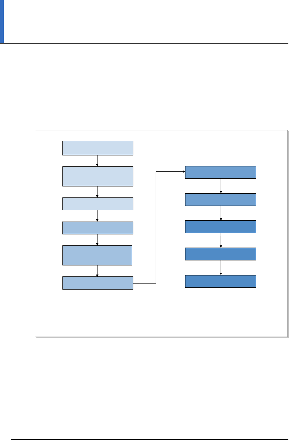
2.1 Installation Procedure
The following diagram shows RRH-C2A installation procedure.
Figure 2.1 System Installation & Cable Connection Procedure
Cabling in the Cabinet
Cabling the Hybrid Cable
Check
* This procedure may be omitted when using an existing installation. If required, additional work can be
done through the standard procedure, and thus will not be described in this manual.
Antenna Installation
Material Check
* Antenna Mounting
System Installation
Cabling from Antenna
to RRH
RRH Installation
* Buss bar Installation
RRH Grounding
Cabling in the RRH
CHAPTER 2. Installation of RRH-C2A
2-2 © SAMSUNG Electronics Co., Ltd.
2.2 Foundation Work
2.2.1 Equipment Arrangement
A minimum distance must be secured around the RRH-C2A in each direction for
installation and maintenance.
Table 2.1 Recommended Distances for System Arrangement
Item Recommended Distances
Front/Rear 800 mm or more
Sides 600 mm or more
Clearance between racks 60 mm (when the battery cabinet is on the left and the DU cabinet is
on the right)
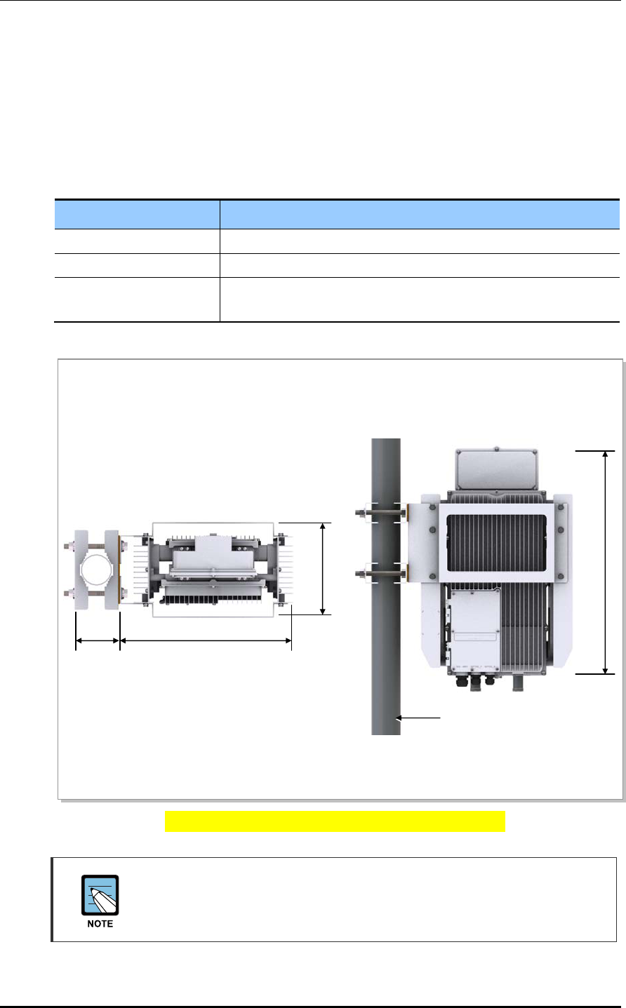
Figure 2.2 RRH-C2A Installation Space (1 sector pole type)
Equipment Installation Space
The figure above illustrates the installation space using a 101.6 mm(90 A)
diameter pole. The measures may differ depending on the diameter of the pole.
≒239
[Unit: mm]
≒440
598
Pole (Ф60.5~101.6 mm)
≒141.6

Smart MBS RRH-P4 Installation Manual/Ver.2.0
© SAMSUNG Electronics Co., Ltd. 2-3
2.3 Unpacking and Transporting
This paragraph describes the work to unpack cabinets and other components and transport
them to the place to be installed. The cabinet is externally packed and cabinet and other
components are individually packed.
The external packing should be unpacked outside of the building. If necessary, it can
be unpacked after transporting to the area near installation place.
Transport the cabinet to the installation place. Be aware of the damage of walls, pillars,
and bottom of the passage when transporting the cabinet.
Transport other components with packing and sort by types.
2.3.1 Importing Items
To import items, be aware of the followings:
Regarding equipment weight and size, check the path to bring the equipment.
Lay Iron and veneer boards on stairs or doorsills to make the transportation easy.
When bring in equipment, beware of damage or impairment of main entrance, walls,
pillars, and floors of the station. Prepare protection materials and fix them with a high-
strength adhesive.
Carry boards in packing status, and unpack them when installing or mounting.
Vibration Level for Transportation
When carrying the system, fasten the system firmly not to exceed the proper vibration
level from 1 to 500 Hz.
When carrying system, use a lift to prevent accidents. However, if the system should
be carried by people, enough people are required to carry the system.
Before moving the system, check the storage place for the system and remove
obstacles in advance. While moving system, boards and other devices should not be
shocked physically and damaged caused by dust, moisture, and static electricity.
When installing the items imported, abide by the following:
System should be installed in a location whose access is not easy from outside.
2.3.2 Unpacking Items
The procedure to unpack items is as follows:
The packing items should be packed until they reach the installation place.
The items are classified in accordance with each job specification and stored on a
place with no interference on working.
Unpacked systems should be installed immediately. If not installed immediately, the
systems should be stored in the installation place temporarily.
Unpack the inner packaging after each system is placed on its installation location.
Unpack the inner packaging after each system is placed on its installation location.
Do not recycle the packaging waste. Dispose of them pursuant to the rules.
CHAPTER 2. Installation of RRH-C2A
2-4 © SAMSUNG Electronics Co., Ltd.
2.4 Fixing the System
2.4.1 Fixing Wall Mount
Follow the steps below to fix the RRH-C2A to the wall.
1) Fix the RRH mounting bracket to the wall. (A)
2) Fix the RRH-C2A to the RRH mounting bracket. (B-D)
Figure 2.3 Fixing Wall Mount (1)
A
) 벽면 드릴링 된 홀에 M12 Hex. bolt, spring washer, plane washer, insulation bushing, Bakelite,
strong anchor 를 사용하여 RRH mounting Bracket-L/R 을 견고하게 고정한다.
M12 Hex. Bolt
M12 Spring Washe
r
M12 Plane Washe
r
M12 Strong Ancho
r
RRH Mounting Bracket-L
M12 Insulation Bushing
Bakelite
RRH Mounting Bracket-R
Smart MBS RRH-P4 Installation Manual/Ver.2.0
© SAMSUNG Electronics Co., Ltd. 2-5
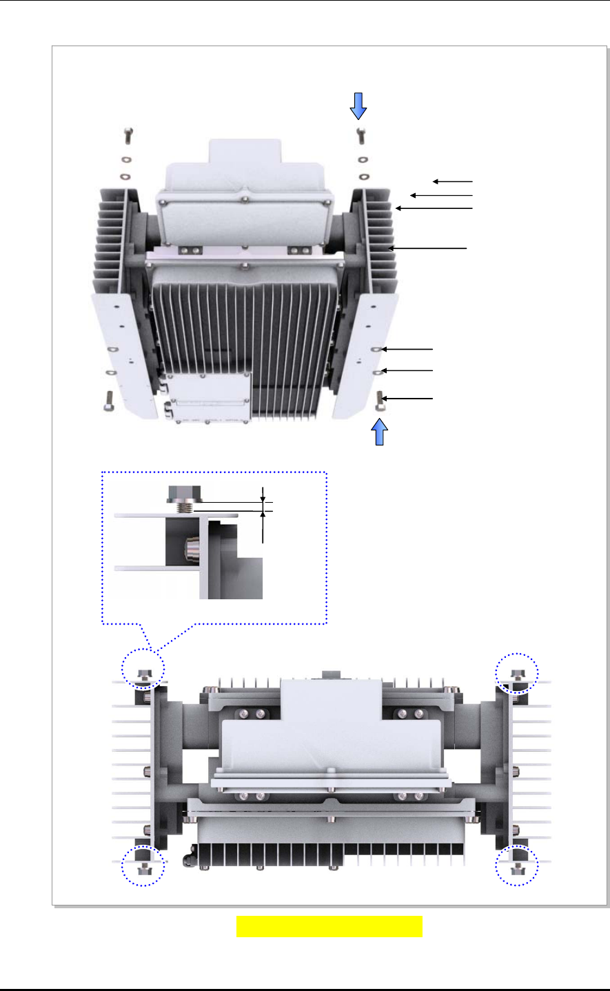
Figure 2.4 Fixing Wall Mount (2)
B) RRH-C2A 상단 좌/우측 고정 홀에 M8 × 25L Hex. bolt, plane washer, spring washer 를 약 6 mm 가량
남도록 하여 임시로 고정한다.
M8 x 25L Hex. Nut
RRH-C2A
M8 Spring Washer
M8 Plane Washer
M12 Plane Washer
M12 Spring Washer
M12 x 25L Hex. Bolt
≒ 6 mm
CHAPTER 2. Installation of RRH-C2A
2-6 © SAMSUNG Electronics Co., Ltd.
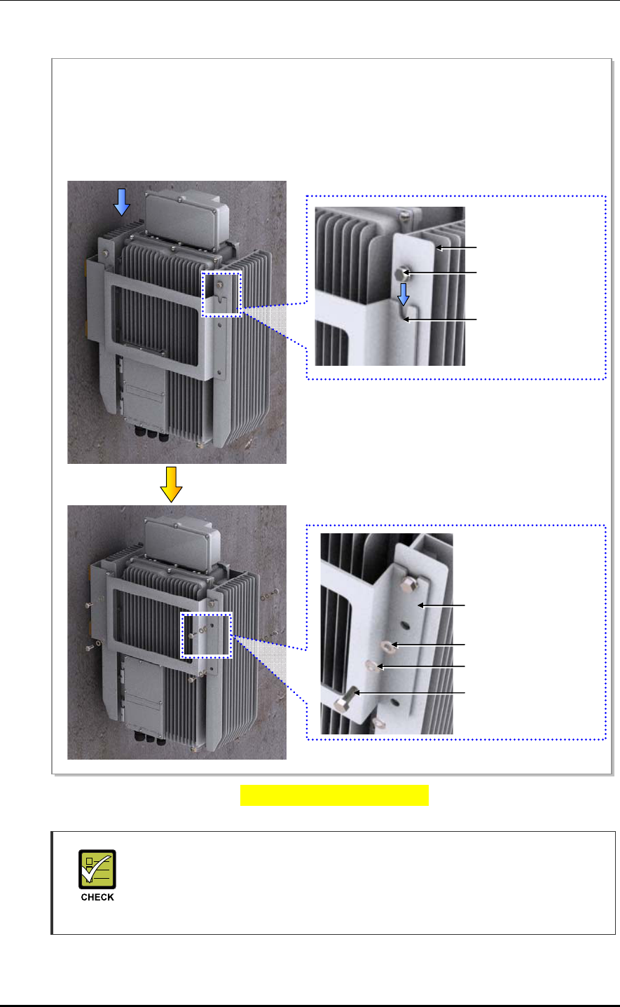
Figure 2.5 Fixing Wall Mount (3)
Cautions When Using Wall Mount Fasteners
The fasteners used to attach the wall mount, including the anchor bolt, spring
washer, plane washer and Hex. nut must be made of stainless steel (STS 304).
Otherwise, it may cause corrosion and rust to fixing materials.
C) RRH-C2A 상단 좌/우측 고정된 M8 × 25L Hex. bolt, plane washer, spring washer 를 RRH mounting
bracket 상단의 홈에 맞춰서 걸고, 나머지 고정 홀에 M8 × 25L Hex. bolt, plane washer, spring
washer 를 사용하여 고정한다.
D) RRH-C2A 상단 좌/우측에 임시로 고정한 M8 ×25L Hex. bolt 를 견고히 고정한다.
RRH-C2
M8 × 25L Hex. Bolt
M8 Spring Washer
M8 Plane Washer
RRH Mounting Bracket
top slot
M8 × 25L Hex. Bolt
M8 Spring Washer
M8 Spring Washer
RRH Mounting Bracket
Smart MBS RRH-P4 Installation Manual/Ver.2.0
© SAMSUNG Electronics Co., Ltd. 2-7
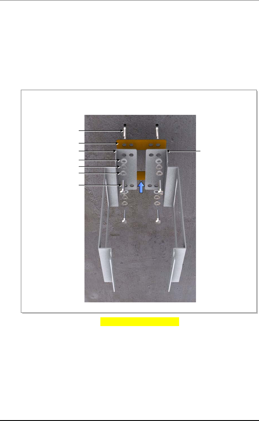
2.4.2 Fixing 1 Sector Pole
Follow the steps below to fix the RRH-C2A to the pole.
1) Fix the RRH mounting bracket and the pole mount bracket each other. (A)
2) Fix the RRH mounting bracket assembly to the pole. (B)
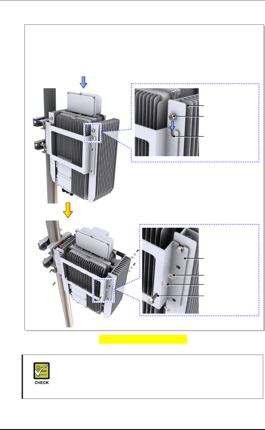
3) Fix RRH-C2A to the RRH mounting bracket. (C~E)
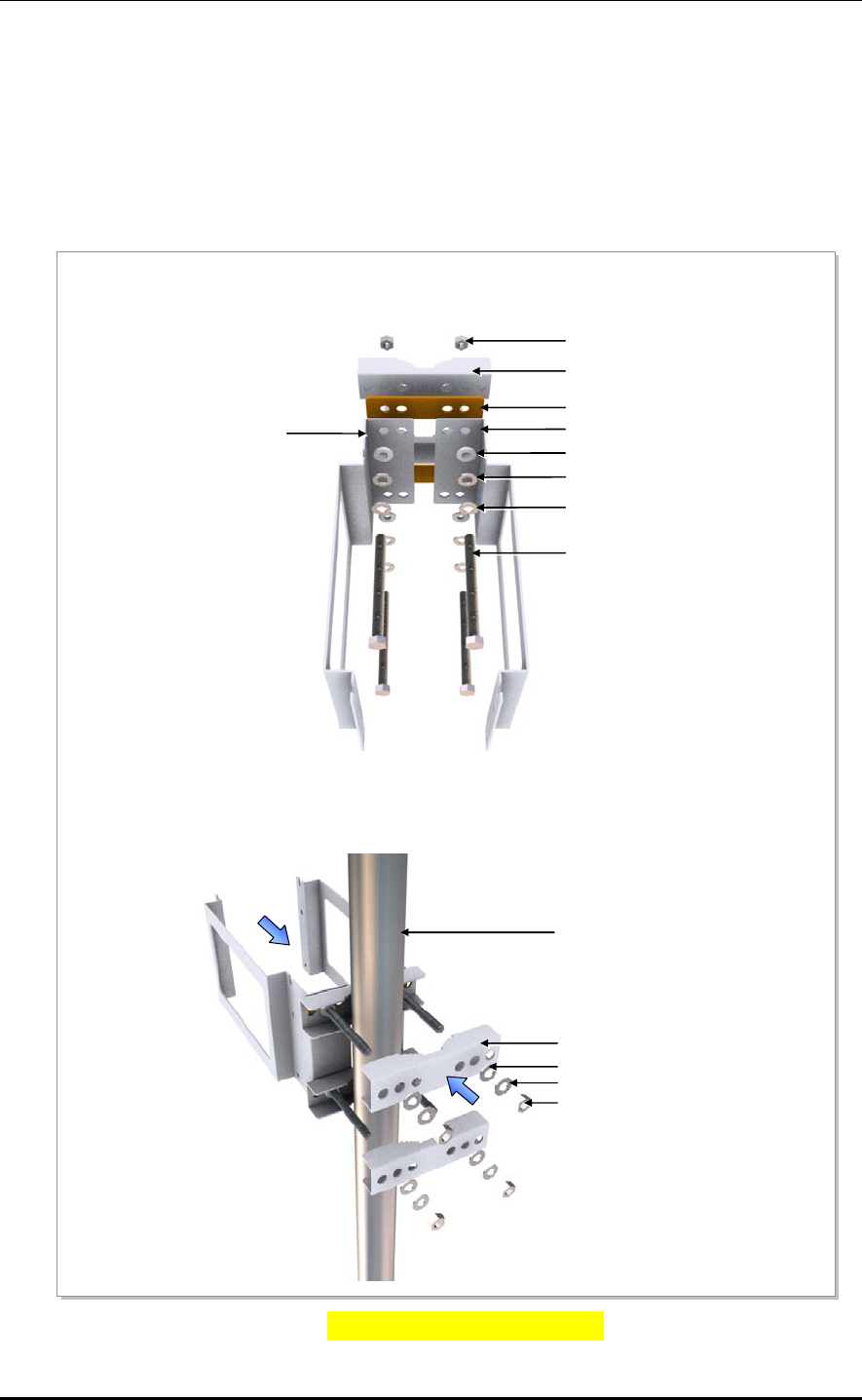
Figure 2.8 Fixing 1 sector pole (1)
A
) RRH mounting bracket-L/R, bakelite, pole mount bracket 의 홀 위치를 맞추고, M12 ×180L Hex. bolt,
spring washer, plane washer, Insulation bushing, Hex. nut 를 사용하여 견고히 고정한다.
B) 조립된 RRH mounting bracket ass’y 를 pole 고정 위치에 놓고, 반대쪽에서 pole mount bracket 을
M12 x 180L Hex. bolt 에 맞추어 끼운 후 M12 plane washer, spring washer, Hex. nut 를 이용하여
견고하게 고정한다.
M12 Insulation Bushing
M12 Hex. Nut
Pole Mount Bracket
Bakelite
M12 Plane Washer
M12 Spring Washer
M12 x 180L Hex. Bolt
RRH Mounting Bracket-R
RRH Mounting Bracket-L
Pole
M12 Spring Washer
M12 Plane Washer
Pole Mount Bracket
M12 Hex. Nut
CHAPTER 2. Installation of RRH-C2A
2-8 © SAMSUNG Electronics Co., Ltd.
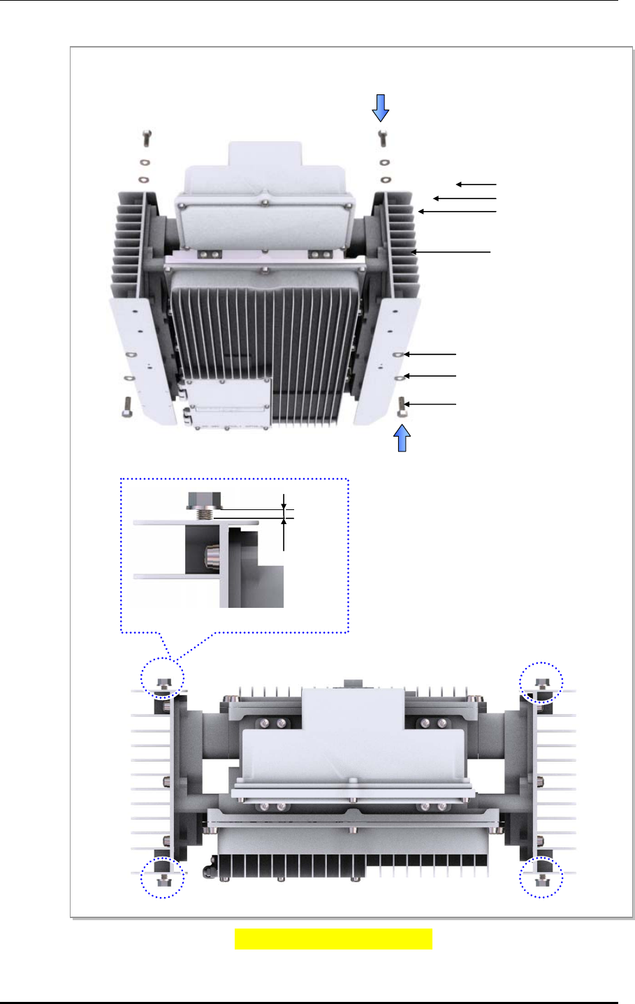
Figure 2.9 Fixing 1 sector pole (2)
C) RRH-C2A 상단 좌/우측 고정 홀에 M8 × 25L Hex. bolt, plane washer, spring washer 를 약 6 mm 가량
남도록 하여 임시로 고정한다.
M8 x 25L Hex. Nut
RRH-C2A
M8 Spring Washer
M8 Plane Washer
M12 Plane Washer
M12 Spring Washer
M12 x 25L Hex. Bolt
≒ 6 mm
Smart MBS RRH-P4 Installation Manual/Ver.2.0
© SAMSUNG Electronics Co., Ltd. 2-9
Figure 2.10 Fixing 1 sector pole (3)
Cautions When Using Pole Fasteners
The fasteners used to attach the pole, including the hex. bolts, hex. nut, spring
washers and plane washers must be made of stainless steel (STS 304).
Otherwise, it may cause corrosion and rust to fixing materials.
D) RRH-C2A 상단 좌/우측 고정된 M8 × 25L Hex. bolt, plane washer, spring washer 를 RRH mounting
bracket 상단의 홈에 맞춰서 걸고, 나머지 고정 홀에 M8 × 25L Hex. bolt, plane washer, spring
washer 를 사용하여 고정한다.
E) RRH-C2A 상단 좌/우측에 임시로 고정한 M8 ×25L Hex. bolt 를 견고히 고정한다.
RRH-C2
M8 × 25L Hex. Bolt
M8 Spring Washer
M8 Plane Washer
RRH Mounting Bracket
top slot
M8 × 25L Hex. Bolt
M8 Spring Washer
M8 Spring Washer
RRH Mounting Bracket
CHAPTER 2. Installation of RRH-C2A
2-10 © SAMSUNG Electronics Co., Ltd.
2.5 Connecting cable between RRH and Antenna
2.5.1 Connecting Feeder Line
Follows the steps below to connect the feeder line.
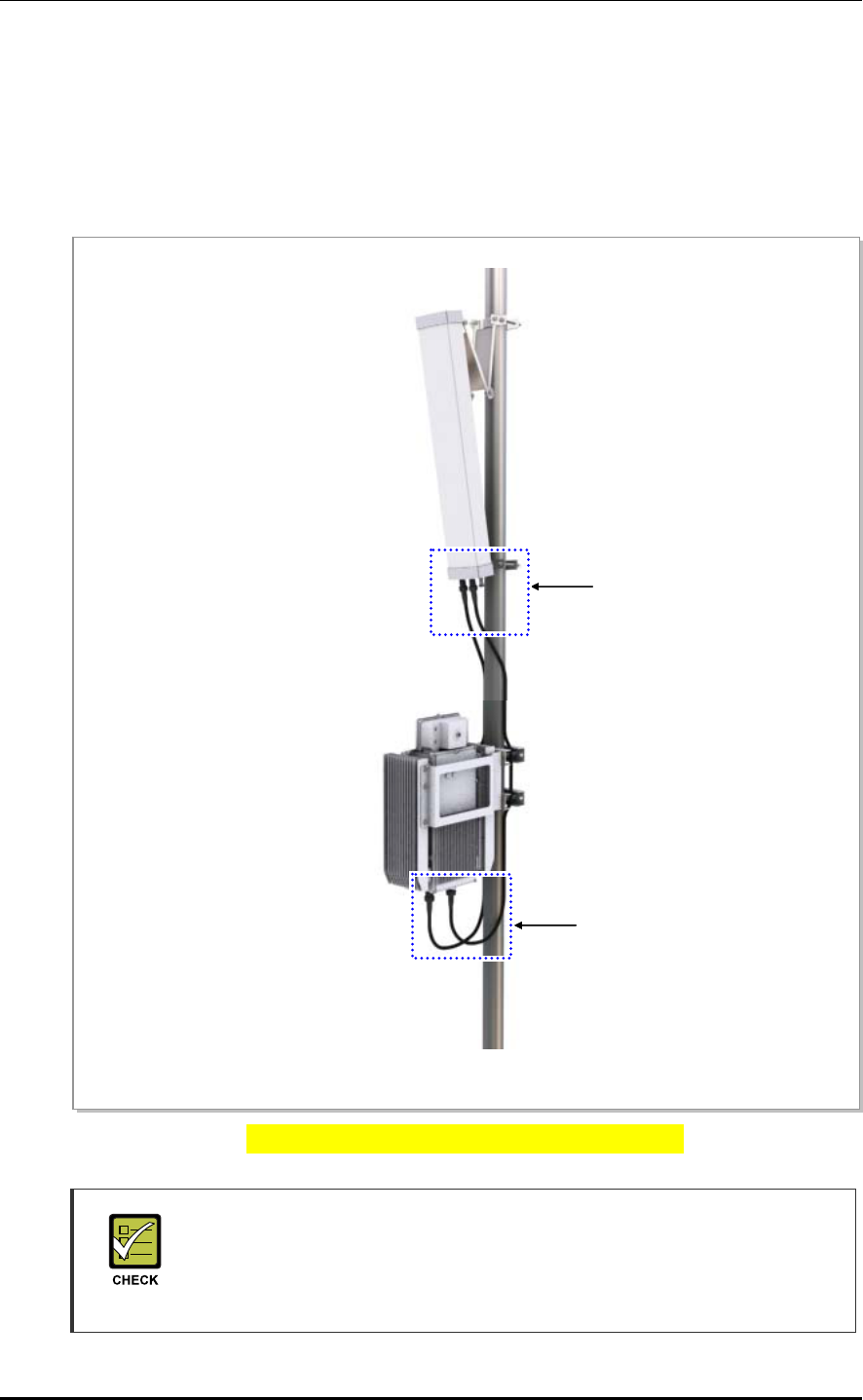
Figure 2.7 RRH-C2A Feeder Line Connection Diagram
Caution for connecting Feeder Line Connector
When connecting the feeder line between RRH-C2A RF port and RF antenna,
each port and the feeder line connector should be secured by 200 kgf.cm torque
to minimize influence of PIMD.
RRH-C2A
RF Antenna
‘A’
‘B’
Smart MBS RRH-P4 Installation Manual/Ver.2.0
© SAMSUNG Electronics Co., Ltd. 2-11
1) Install 1/2 inch feeders line from the RF port at the bottom of RRH-C2A to the RF
antenna.
2) Insert a heat shrink tube (jelly type) to each end of the installed 1/2 inch feeder lines,
then connect a din-male connectors to the RRH-C2A’s RF port and the RF antenna
port.
3) After installing the connector, shrink the heat shrink tubes using a heat gun.
Figure 2.8 Connecting RRH-C2A Feeder Line (1)
Detail ‘A’
Din-Type Male Connector
Heat Shrink Tube (Jelly Type)
1/2 in. Feeder Line
CHAPTER 2. Installation of RRH-C2A
2-12 © SAMSUNG Electronics Co., Ltd.
Figure 2.9 Connecting RRH-C2A Feeder Line (2)
Caution for connecting Feeder Line Connector
When connecting the feeder line between RRH-C2A RF port and RF antenna,
each port and the feeder line connector should be secured by 200 kgf.cm torque
to minimize influence of PIMD.
Detail ‘B’
A
ntenna Connector(Din-Female)
1/2 in. Feeder Line
Heat Shrink Tube(Jelly Type)
RF Antenna
Din-Type Male Connector
for 1/2 In. Feeder Line
Smart MBS RRH-P4 Installation Manual/Ver.2.0
© SAMSUNG Electronics Co., Ltd. 2-13
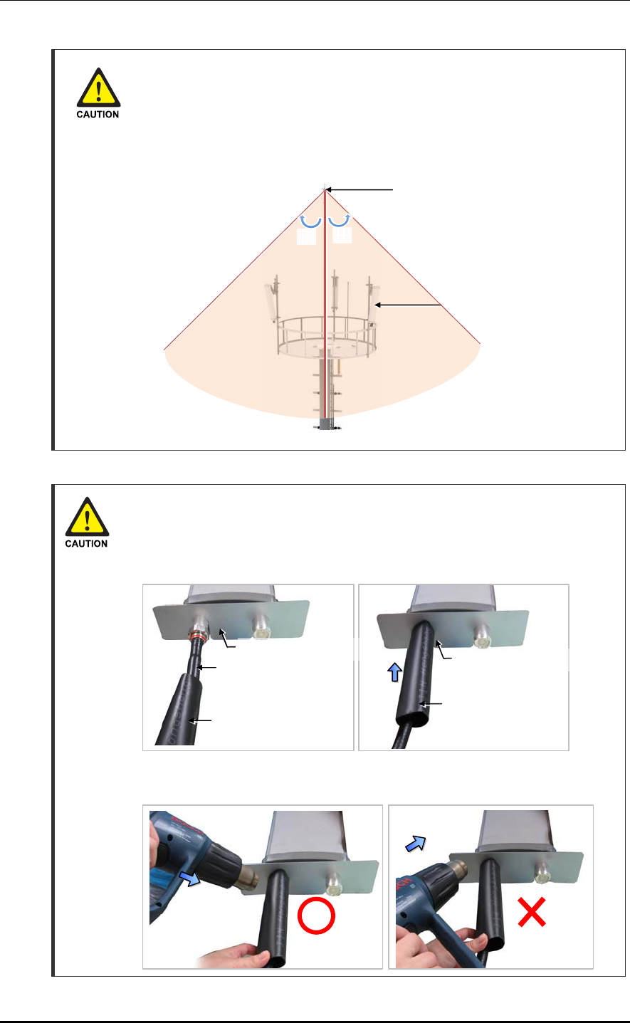
Caution when Installing the RF antenna
To protect from lightning, the RF antenna must be installed within the shielding
angle as shown below, considering the downward distance and the angle from
the tower lightning rod or the antenna pole lightning rod.
- The protection angle of the lightning rod should be 45 degrees.
Finishing Heat Shrink Tube of a Sector Antenna
1) Insert an antenna protection plate.
2) Place the heat shrink tube on the connection point and shrink the heat shrink
tube using a heat gun.
3) Avoid aiming the heating gun toward the antenna’s body as shown in the figure
below.
Lightning rod
45°45°
RF Antenna
Heat Shrink Tube
(Jelly Type)
A
ntenna Jumper Cable
(1/2 in. Feeder Line)
Heat Shrink Tube
(Jelly Type)
A
ntenna Protection Plate
A
ntenna Protection Plate
CHAPTER 2. Installation of RRH-C2A
2-14 © SAMSUNG Electronics Co., Ltd.
Checking Feeder line Connection
After connecting the feeder line, perform the continuity test and feeder cable return loss to
check if the feeder cable is changed and measure VSWR of antenna and feeder cable.
VSWR Standard
The standing wave ratio (VSWR) of the cable and connector between the system’s
RF port to the antenna port must be smaller than 1.5 dB (return loss: 14 dB).
If a separate standard has been established with the career, the established
standard will take precedence.
Identification tag installation
Attach the identification tag in the below table to the feeder line.
Table 2.2 GPS Identification Tag of Feeder line
Category Description
Installation position Attach the identification tag to the both ends of the antenna.
Materials Use the material of aluminum coated by vinyl for the identification tag.
Fixing method Fix the feeder cable to the 2 holes on the identification tag with the black
cable tie.
Marking The markings must be prevented from being erased by using relief engraving
or coated labels.
Antenna
System’s external ‘I connector’
connection
Smart MBS RRH-P4 Installation Manual/Ver.2.0
© SAMSUNG Electronics Co., Ltd. 2-15
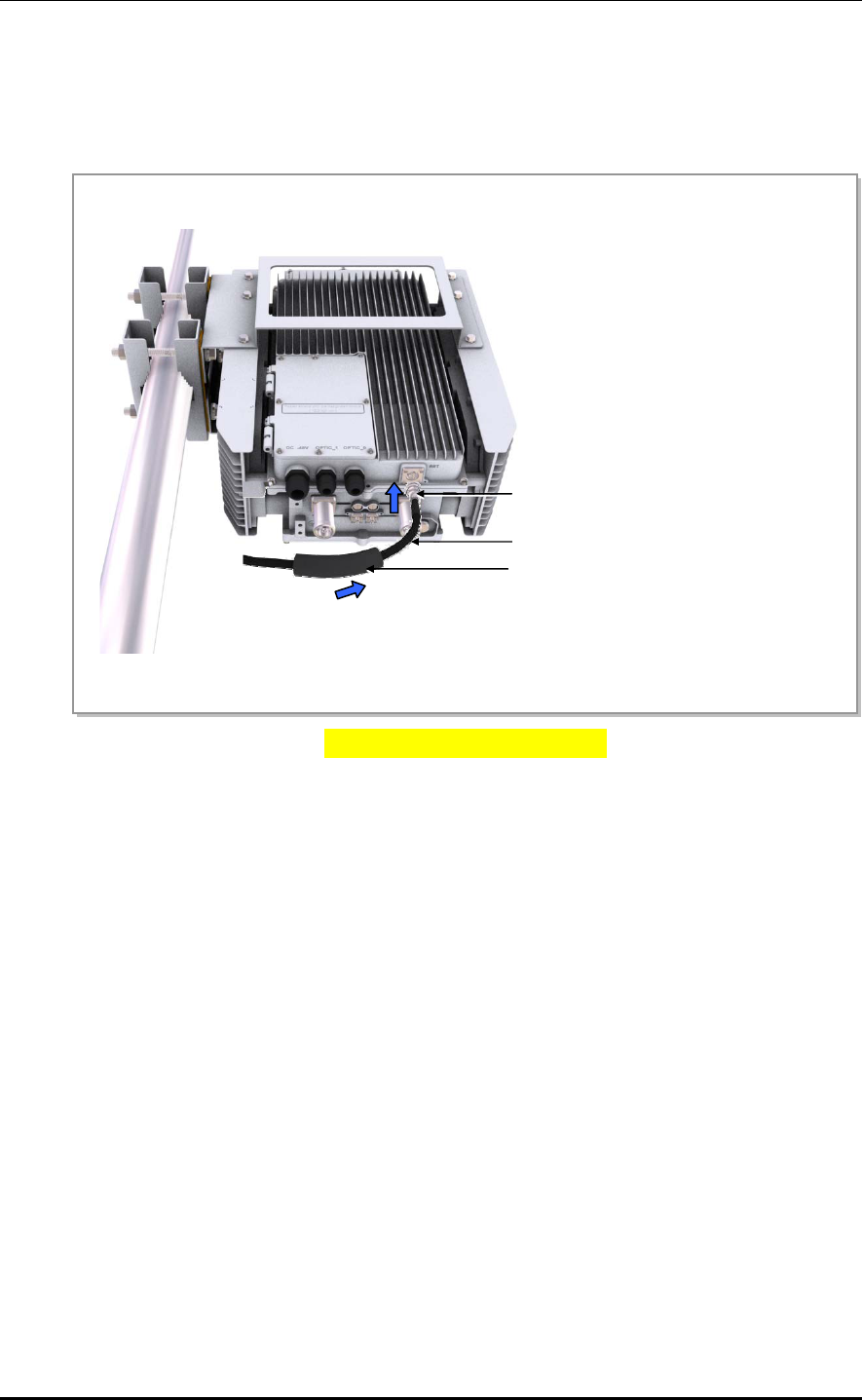
2.5.2 Connecting RET cable
Follow the steps below to connect the Remote Electrical Tilting (RET) cable used to
control the tilting angle of the antenna from the distance.
Figure 2.10 Connecting RET cable
RET Connector (SAMWOO, SU-20SP-8P)
Heat Shrink Tube (Jelly Type, Black)
RET Cable (Shield Cable)
CHAPTER 2. Installation of RRH-C2A
2-16 © SAMSUNG Electronics Co., Ltd.
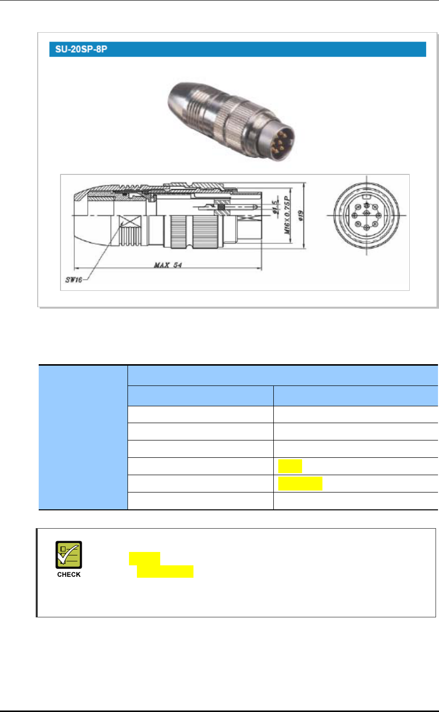
Figure 2.11 RET Cable connector
Table 2.3 RET Cable-Side Connector Pin Map
RET Connector
Samwoo, SU-20SP-8P
Pin Function
3 RS485B
4 DGND
5 RS485A
6 +28 V
7 +28 V RTN
1, 2, 8 NC
RET
- When 28 VDC volts are applied, the current supplied to the RET from RRH-C2A
must be lower than 1 A.
- The exterior of the RET connector must be made of metal without vent hole or
other UL certified material.
Smart MBS RRH-P4 Installation Manual/Ver.2.0
© SAMSUNG Electronics Co., Ltd. 2-17
2.6 Connecting ground cable
2.6.1 Grounding RRH-C2A
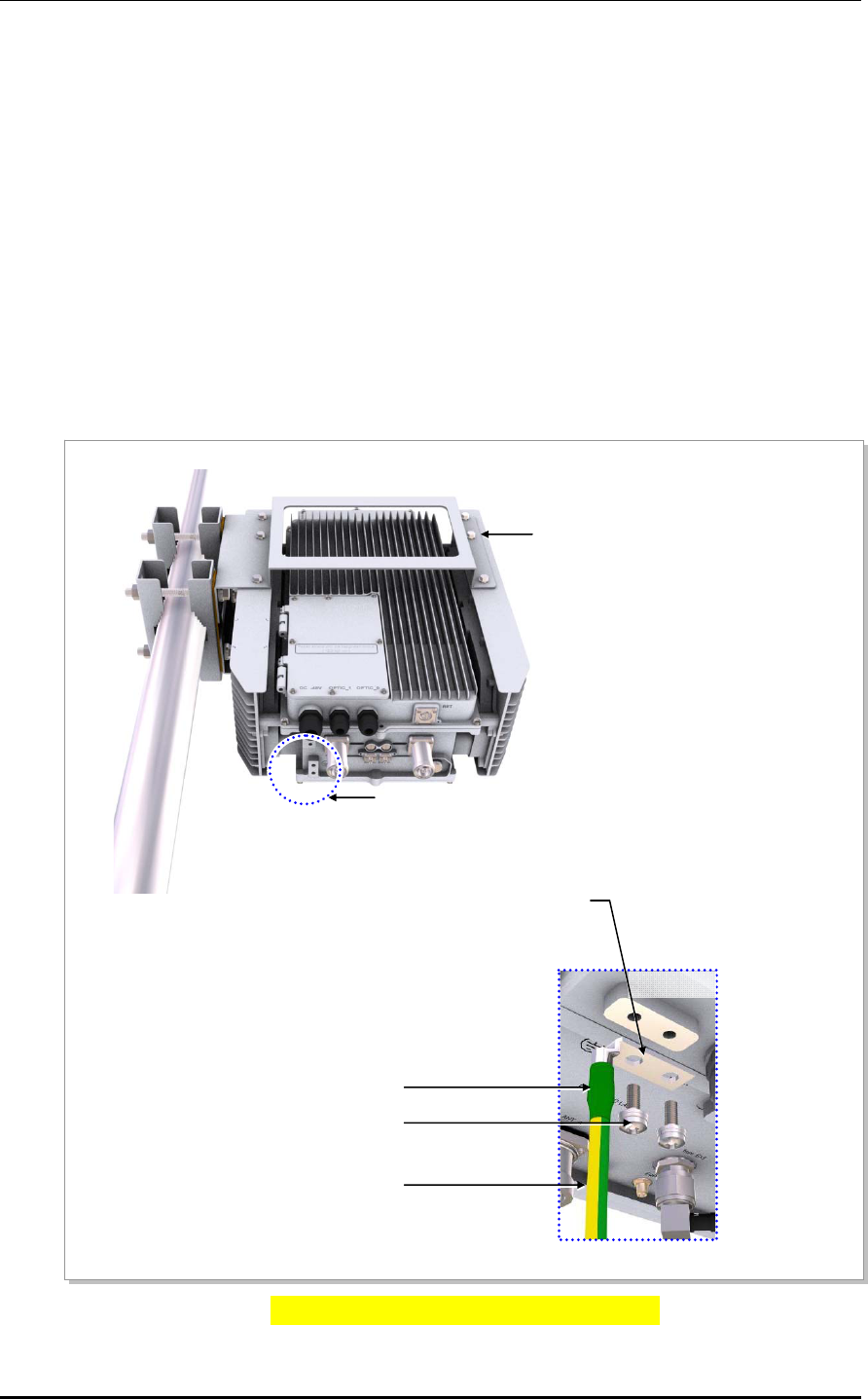
Follow the steps below to connect the RRH-C2A ground cable.
1) Install one ground cable (AWG8, GV 6 mm2 × 1 C) from MGB to the ground terminal
at the bottom of RRH-C2A.
2) Install the 6 mm2 pressure terminal and the heat shrink tube at the end of the cable.
3) Place the pressure terminal at one end of the ground cable of RRH-C2A aligning with
the fixing holes and fix it using M6 SEMS.
(When being secured by screw, apply 38.16~46.64 kgf.cm torque.)
Figure 2.12 Connecting RRH-C2A Ground cable
M6 x 12L SEMS
Ground Cable(AWG8, GV 6 mm2 × 1C)
From MGB(Main Ground Bar)
Detail ‘A’
Heat Shrink Tube(Green)
6 mm2 Pressure Terminal
(2Hole, 90°, Hole diameter: 6.3 mm,
Hole distance: 16 mm)
RRH-C2A
‘A’
CHAPTER 2. Installation of RRH-C2A
2-18 © SAMSUNG Electronics Co., Ltd.
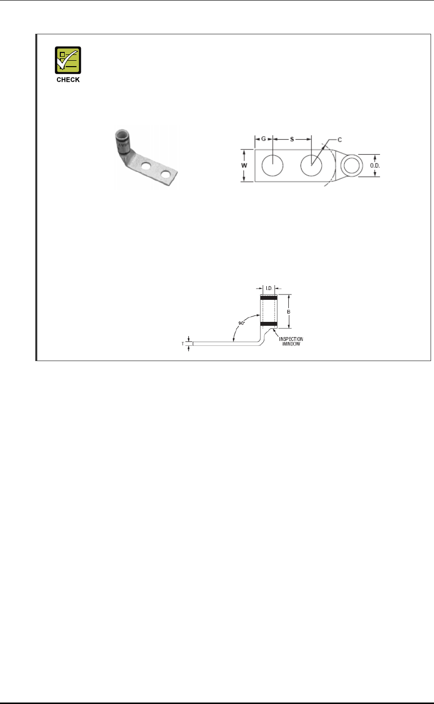
Pressure terminal
As for the pressure terminal or the cable, the UL certified products or equivalent
should be used.
Ex) Manufacturer-Panduit
RRH-C2A: 6 mm2 Type Name (LCD8-14AF-L)
When connecting the pressure terminal to a cable, remove the cable sheath
where the pressure terminal is connected, and then push the cable all the way to
the end of the cable lead-in part.
Check the position of the coaxial cable through the inspection window of the
pressure terminal before compressing it with a compressor.
Smart MBS RRH-P4 Installation Manual/Ver.2.0
© SAMSUNG Electronics Co., Ltd. 2-19
2.7 Connecting Hybrid cable
2.7.1 Installing Hybrid cable
Follow the steps below to install the hybrid cable.
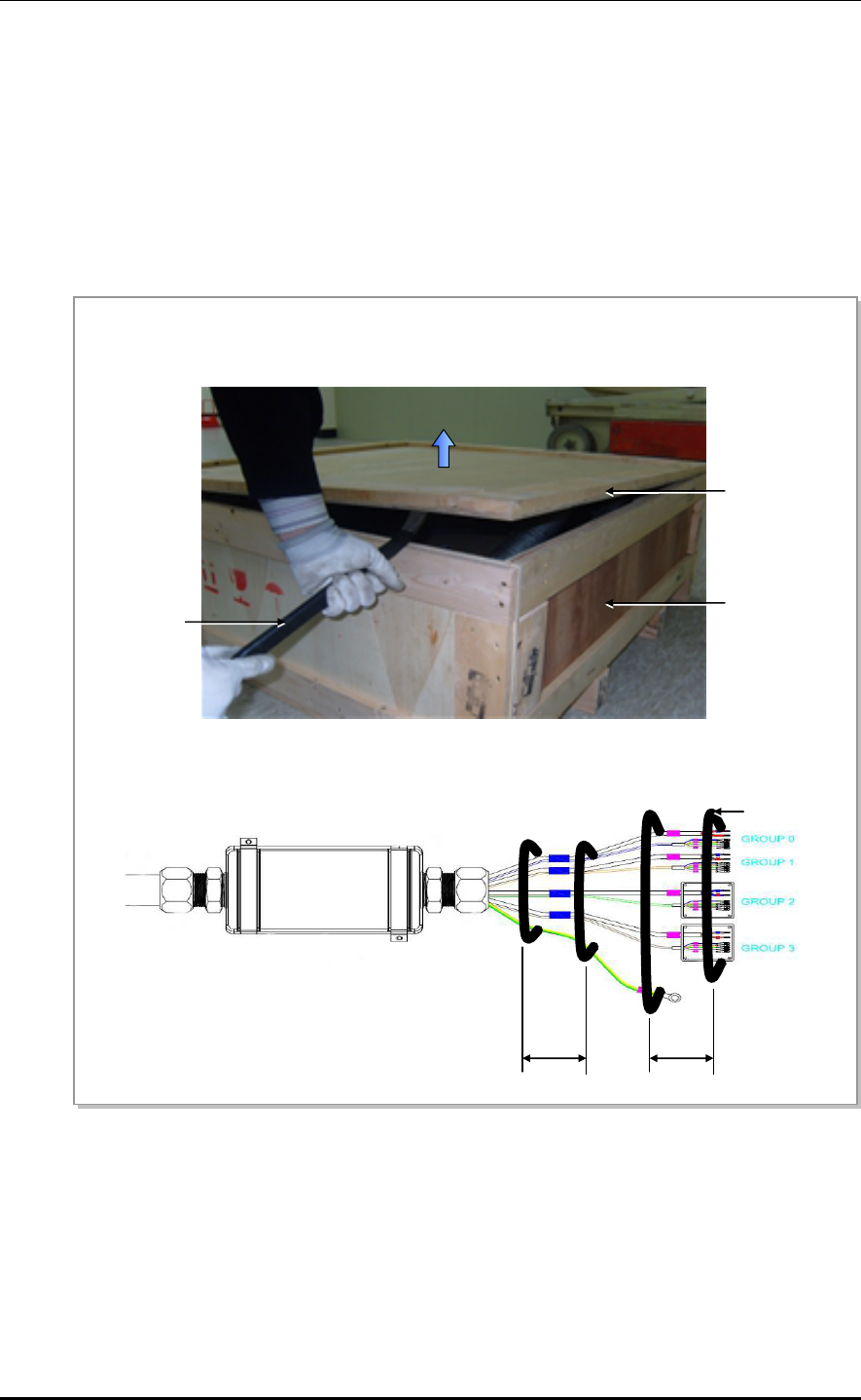
1) Unpack the box. (A-D)
2) Pull up the tower. (E-F)
Figure 2.13 Installing Hybrid cable (1)
A
) Use a crowbar to open the wooden box cover.
After opening the cover, ensure to remove the remaining nails as they may cause injury.
B) Hold both ends of the hybrid cable and lift it out of the box. Tape the power cable and optic cable
separately at 1 m interval. Also, tape the exposed optic connector to prevent damage.
1 m
...
Tape
1 m
Cover
Crowba
r
Wooden Box
CHAPTER 2. Installation of RRH-C2A
2-20 © SAMSUNG Electronics Co., Ltd.
Figure 2.14 Installing Hybrid cable (2)
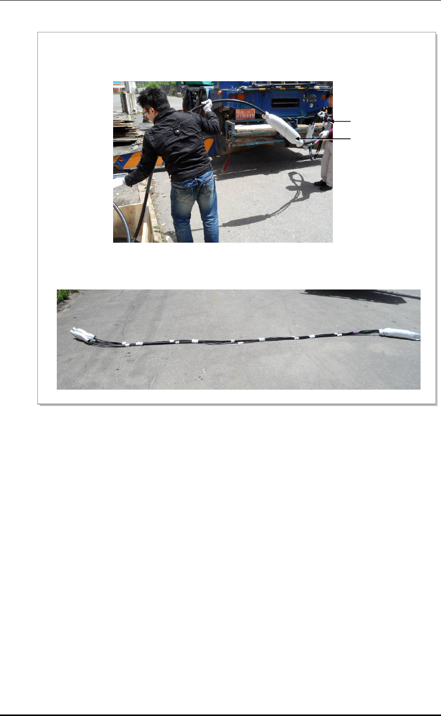
C) Take the cable out of the box paying attention not to impact the junction box and the jumper cable.
Be careful not to drag the jumper cable on the floor.
D) Lay the hybrid cable on the floor.
Junction Box
Jumper Cable
Smart MBS RRH-P4 Installation Manual/Ver.2.0
© SAMSUNG Electronics Co., Ltd. 2-21
Figure 2.15 Installing Hybrid cable (3)
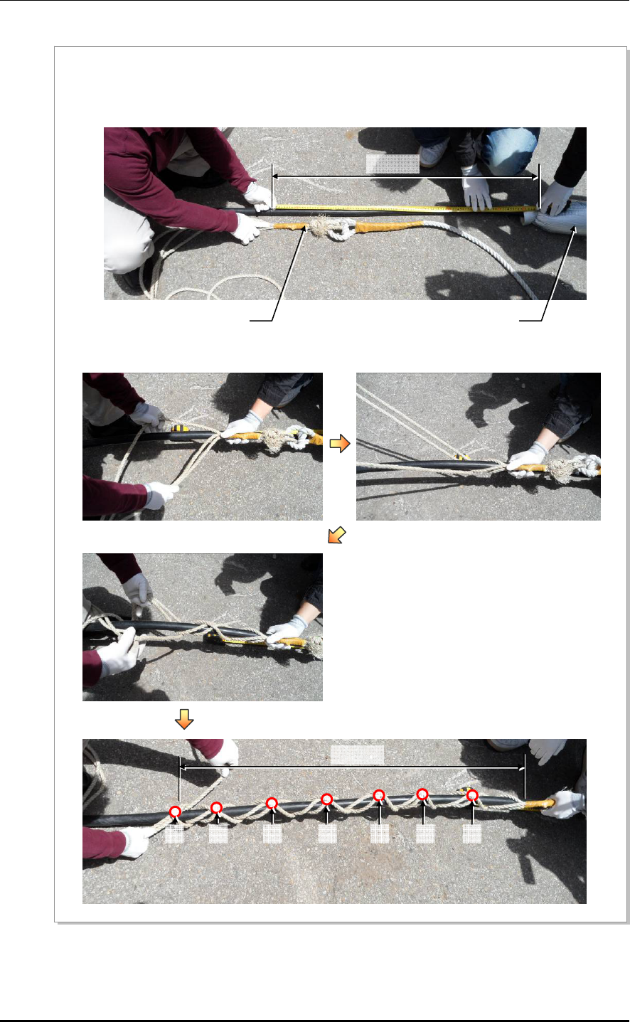
E) Install pulling wire to the 1m point of (RRH side) hybrid cable's junction box(breakout point) bottom.
Wind the pulling wire by 7 times or more to the 1 m or more length of hybrid cable.
Junction Box
(Breakout Point)
Min. 1 m
Pulling Wire
Min. 1 m
1 2 3 4 5 6 7
CHAPTER 2. Installation of RRH-C2A
2-22 © SAMSUNG Electronics Co., Ltd.
Figure 2.16 Installing Hybrid cable (4)
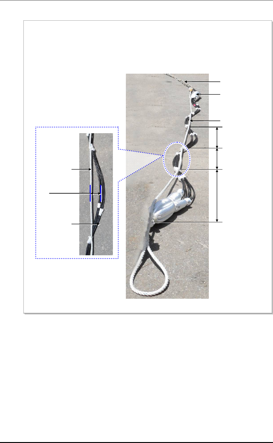
F) Fix the cable to the hoisting wire with a cable tie at regular intervals (within 1 m) to prevent impact or
tension to the upper side of the junction box when lifting the hoist.
Maintain hoisting wire in a straight line, separate the RRH-side cable's curve from the hoisting wire
with 150mm or more distance. And fix cable and wire with cable tie.
(When lifting the hoist, be careful not to apply tension to other areas of the hybrid cable except where
the pulling wire is attached.)
Max. 1 m
Junction Box
(Breakout Point)
Pulling Wire
Hoisting Wire
Max. 1 m
Max. 1 m
Hoisting Wire
Hybrid Cable
More than 150 mm
Smart MBS RRH-P4 Installation Manual/Ver.2.0
© SAMSUNG Electronics Co., Ltd. 2-23
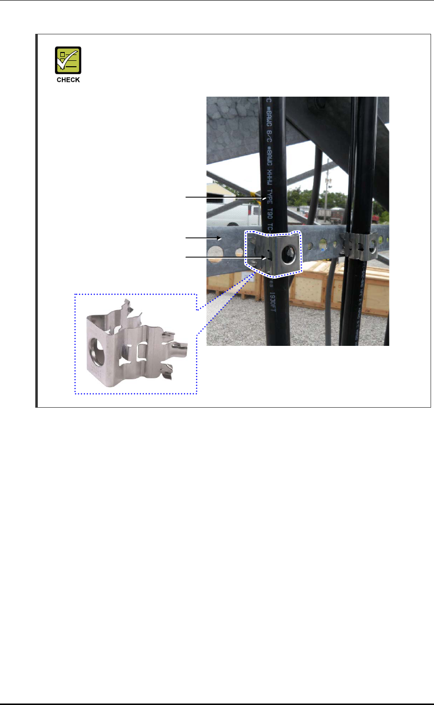
Hybrid cable mounting clamp and installation standards
When fixing hybrid cable to the tower ladder, use the clamp of photo below and fix
use of a clamp, and fix cable with fixed-interval of once per 3feet.
2.7.2 Connecting DU Cabinet side cable
If the length of the hybrid cable is inadequate for the installation:
1) Measure the hybrid cable’s excess length.
(With a white marker pen, mark the area of the cable where the double-layer sheath
will be peeled when positioned in the conduit fitting.)
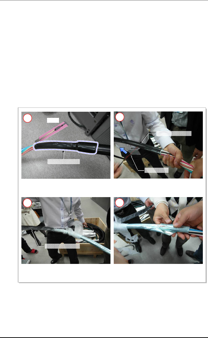
2) Using a knife, peel off the heat shrink tube that binds the cables together.
3) Pull the peeling wire in the inside of the hybrid cable’s double-layer sheath down to
the previously marked area.
4) Peel off the hybrid cable’s sheath.
5) Peel off the aluminum foil wrapped around the inner cable.
6) For all power cables, leave 1000 mm from where the double-layer sheath has been
peeled off and cut the excess length off.
7) Unsheathe the end of the power cable wire at 15 mm.
8) Using a conduit, insert the hybrid cable’s power cable and optic cable together into the
cabinet. Be careful not to damage the optic cable’s connector.
Clam
p
Ladde
r
Hybrid Cable
CHAPTER 2. Installation of RRH-C2A
2-24 © SAMSUNG Electronics Co., Ltd.
9) From the inside of the cabinet, pull the optic cable to the right side of the system and
attach temporarily with a cable tie.
10) Using a flat-head screwdriver (-, 1x100), turn the RRH power terminal’s screw counter-
clockwise twice to 3 times.
11) Insert the power cable to the terminal according to its use and polarity, then fasten the
screw.
12) Bind two cables (-48 V, RTN) at 100 mm from the terminal using a cable tie.
13) Bury the optic cable following the system’s inner-right wall up to the UADU#0 side
and bind using a cable tie.
14) Connect the connector of the optic cable to UADU’s designated port. (Loop the optic
cable’s excess length respecting the bending radius (R=110 mm), and arrange it at the
bottom of the DC power terminal. Be careful not to damage the optic cable during
other works.)
Figure 2.17 Peeling off the Hybrid Cable Sheath
Knife
1) Using a knife, peel off the heat shrink tube
that binds the cables together.
1
Heat Shrink Tube
Peelin
g
Wire
H
y
brid Cable Sheath
2) Pull the peeling wire to cut the hybrid cable’s
sheath.
2
3) Peel off the hybrid cable’s sheath.
H
y
brid Cable Sheath
3 4
4) Peel off the aluminum foil wrapped around the
inner cable.
Smart MBS RRH-P4 Installation Manual/Ver.2.0
© SAMSUNG Electronics Co., Ltd. 2-25
If the length of the hybrid cable is adequate for the installation:
1) For all power cables, leave 1000 mm from where the double-layer sheath has been
peeled off and cut the excess length off.
2) Unsheathe the end of the power cable wire at 15 mm length.
3) Using a conduit, insert the hybrid cable’s power cable and optic cable together into the
cabinet. Be careful not to damage the optic cable’s connector.
4) From the inside of the cabinet, pull the optic cable to the right side of the system and
attach temporarily with a cable tie.
5) Using a flat-head screwdriver (-, 1x100), turn the RRH power terminal’s screw
counter-clockwise 2 to 3 times.
6) Insert the power cable to the terminal according to its usage and polarity, then fasten
the screw.
7) Bind two cables (-48 V, RTN) at 100 mm from the terminal using a cable tie.
8) Bury the optic cable following the system’s inner-right wall up to the UADU#0 side
and bind using a cable tie.
9) Connect the connector of the optic cable to UADU’s designated port. (Loop the optic
cable’s excess length respecting the bending radius (R=110 mm), and arrange it at the
bottom of the DC power terminal. Be careful not to damage the optic cable during
other works.)
Figure 2.18 Connecting Hybrid cable (1)
[Baseband Rack Right View]
RRH Power Terminal
Double-layer Sheath
Peel-off Point
600 mm
RRH CPRI Cable
(Optic Cable)
Flexible Pipe (2 in.)
Max. 1,000 mm
Butyl Rubber Tape
Hybrid Cable
DC Power Cable
CHAPTER 2. Installation of RRH-C2A
2-26 © SAMSUNG Electronics Co., Ltd.
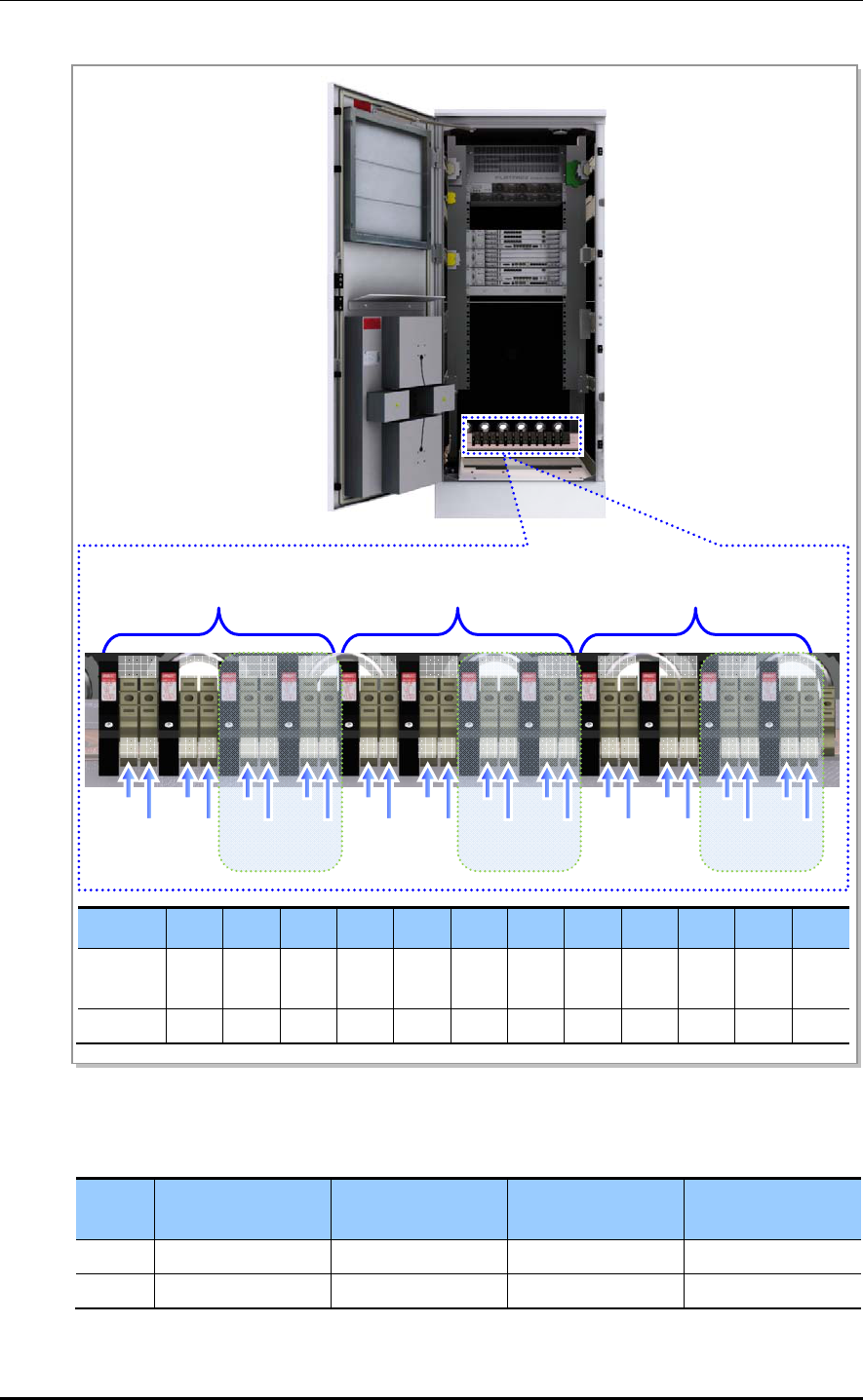
Figure 2.19 Connecting Hybrid cable (2)
Table 2.4 Hybrid Cable Color Map
Group 0
(1.9 GHz)
Group 1
(800 MHz)
Group 2
(2.5 GHz)
Group 3
(2.5 GHz)
Return White/Red stripe White/Black stripe White/Blue stripe White/Brown stripe
-48 V Red Black Blue Brown
(
-
)
RRU 0
RRH DC SPD Terminal
(Alpha)
RRH DC SPD Terminal
(Beta)
RRH DC SPD Terminal
(Gamma)
Reserved Reserved Reserved
-48 V
RTN
-48 V
RTN
-48 V
RTN
-48 V
RTN
-48 V
RTN
-48 V
RTN
-48 V
RTN
-48 V
RTN
-48 V
RTN
-48 V
RTN
-48 V
RTN
-48 V
RTN
- + - + - + - + - + - + - + - + - + - + - + - +
F7 F8 F9 F10 F11 F12 F13 F14 F15 F16 F17 F18
Breaker F7 F8 F9 F10 F11 F12 F13 F14 F15 F16 F17 F18
RRU RRU
#0
RRU
#1
RRU
#2
RRU
#3
RRU
#4
RRU
#5
RRU
#6
RRU
#7
RRU
#8
RRU
#9
RRU
#10
RRU
#11
Capacity 32A 32A 20A 20A 32A 32A 20A 20A 32A 32A 20A 20A
Smart MBS RRH-P4 Installation Manual/Ver.2.0
© SAMSUNG Electronics Co., Ltd. 2-27
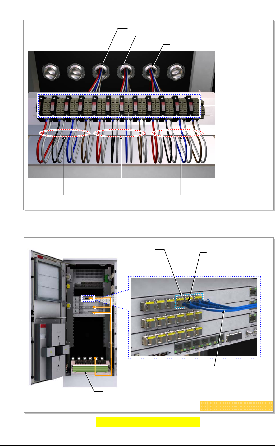
Figure 2.20 Connecting Hybrid cable (3)
Figure 2.21 Connecting Hybrid cable (4)
RRH_ α Power Cable
Conduit#4 (Gamma)
Conduit#3 (Beta)
Conduit#2 (Alpha)
RRH_ β Power Cable RRH_ γ Power Cable
RRH SPD Terminal
(20 A/32 A)
Space for the remainder of RRH CPRI Cable
RRH Interface Connector
(LC/PC)
RRH Interface(CPRI) Cable
(Hybrid Cable)
L9CA-B4T_#2 L3~5 Port
[CPRI Cable Connection]
CHAPTER 2. Installation of RRH-C2A
2-28 © SAMSUNG Electronics Co., Ltd.
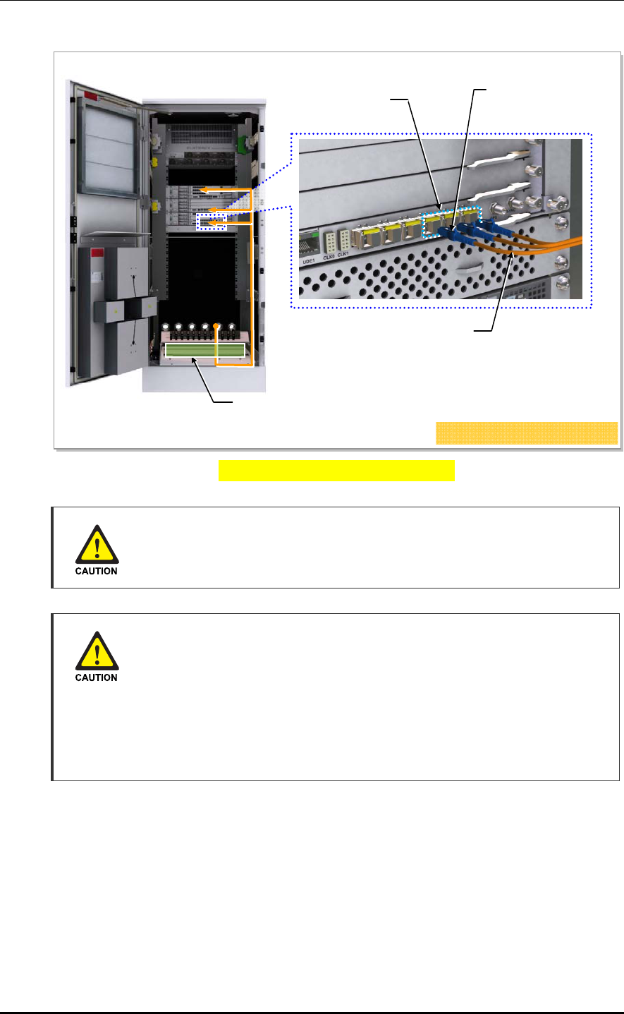
Figure 2.21 Connecting Hybrid cable (5)
Managing unused port
Finish unused port of UADU by dust-cap, not making the alien substance flowed.
Finishing Cable Insertion Hole
Finishing work is required on cable insertion holes (Cable gland, Conduit and
etc.) to prevent entering of any foreign substance, external air and moisture.
- Unused cable insertion hole: Finish cable insertion hole using fishing materials
such as dust cap, rubber packing and etc.
- Cable-installed insertion hole: After installing cable, finish insertion hole using
tape, compressed sponge, rubber packing, silicon, etc. to prevent empty space.
Space for the remainder of RRH CPRI Cable
CIMA-A L3~5 Port RRH Interface Connector
(LC/PC)
RRH Interface (CPRI) Cable
(Hybrid Cable)
[CDMA CPRI Cable Connection]
Smart MBS RRH-P4 Installation Manual/Ver.2.0
© SAMSUNG Electronics Co., Ltd. 2-29
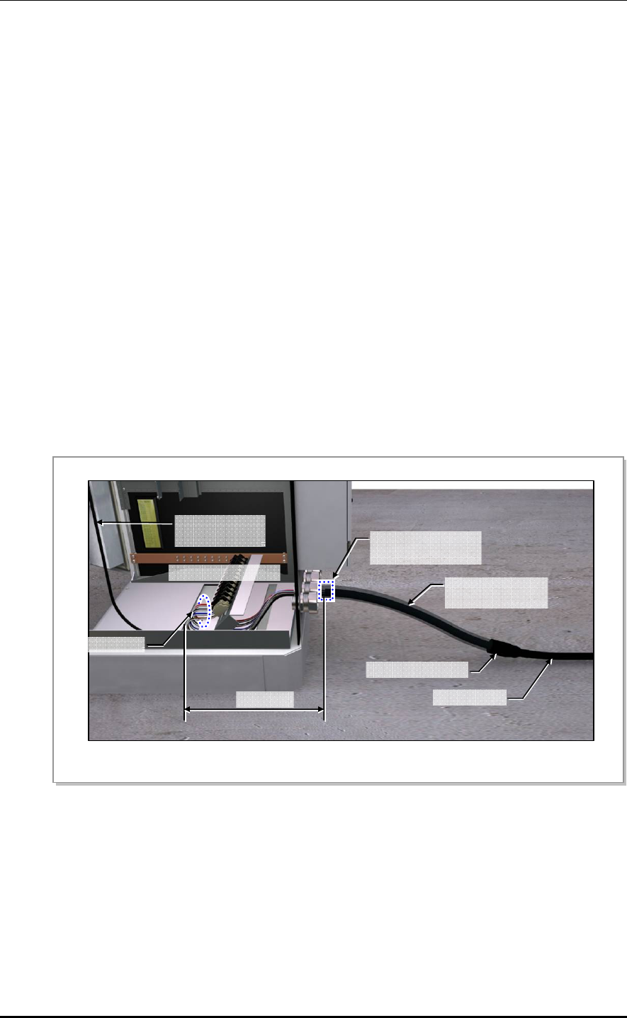
2.7.3 Connecting RRH-C2A Power Cable
When using the power cable (AWG8)
Follow the steps below to connect the power cable to RRH-C2A.
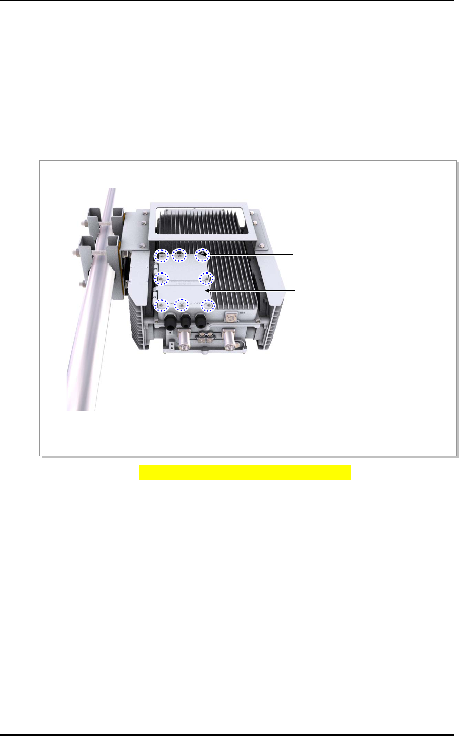
1) Unscrew the power window cover fixing screw located at the rear bottom of RRH-
C2A using a Torx (T20) screwdriver. (The cover fixing screw is designed to remain
attached to the cover.)
Figure 2.22 Connecting RRH-C2A power cable (1)
Cover Fixing Screw(T20)
Install Window Cover
CHAPTER 2. Installation of RRH-C2A
2-30 © SAMSUNG Electronics Co., Ltd.
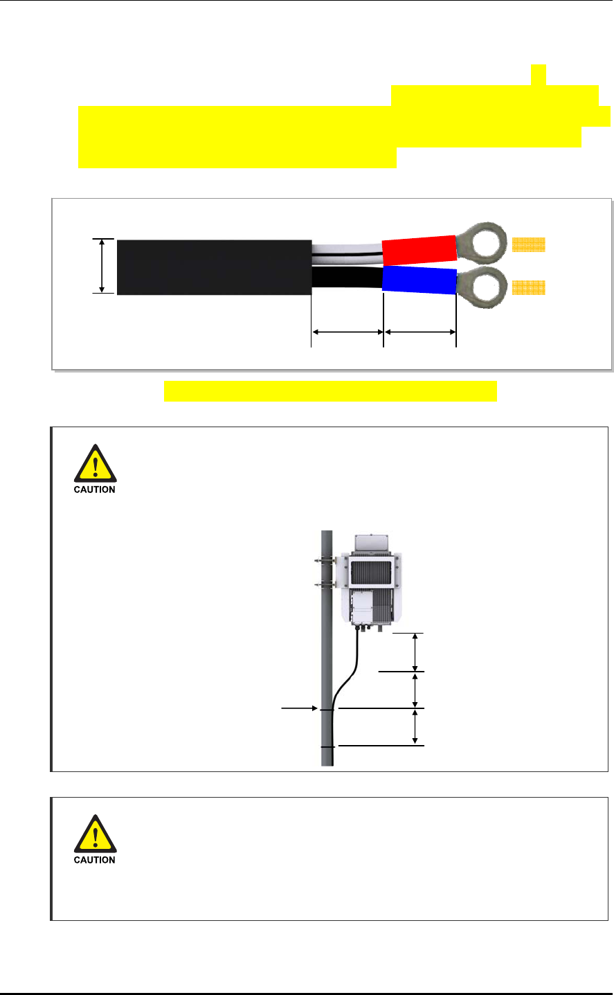
2) Cut cable installed to the power terminal. Unsheathe outer cable sheath at 30 mm
length and peel off the inner wire at 10 mm length. And insert the heat shrink tube of
15 mm length to the wire, then connect the ring lug to the end of each inner wire. Press
and fix the ring lug head to the wire. Next locate the shrink tube as in the as in the
below figure, then shrink the tube with the heat gun.
Figure 2.24 Connecting RRH-C2A power cable (AWG8) (3)
Caution for installing the power cable
To maintain cable gland's rain protection performance, 300 mm or more interval
should be kept straight. According to the radius of curvature of the cable
specification should be considered.
Caution for cutting the power cable
Cut power cable after installing power cable to RRH-C2A power terminal taking
into account the radius of curvature according to the cable specifications.
When cutting the cable first, the length difference of cable end can be occurred by
cable curvature and the power terminal may cause contact fault.
15 mm
14.7 ~
15.4mm
DC Power Cable
(AWG8,Φ14.7~15.4mm)
15 mm
-48V
RTN
Stainless steel Band
or Cable Tie
≒300mm or more
≒300mm
≒300mm

Smart MBS RRH-P4 Installation Manual/Ver.2.0
© SAMSUNG Electronics Co., Ltd. 2-31
5) Remove the cable gland nut from the power cable input hole located at the bottom of
RRH-C2A.
6) Insert the cable gland nut to the power cable (Hybrid cable, AWG8, 2C).
7) Insert the power cable from the bottom of the equipment through the power cable input
hole, then install within the power window. Make sure that the power cable’s unsheathed
part is inserted only as far as the protruded section inside the rain protection sponge.
8) Turn the screws(On the power terminal block) 8 times or more by the opposite direction
of clockwise rotation. So, clamp of the bottom must be moved down completely.
9) Inset power cable(Sheath is stripped) with the correct polarity, fasten the screw by torque
14 kgf.cm.(Refer to the 'Caution for connecting power cable to terminal block')
CHAPTER 2. Installation of RRH-C2A
2-32 © SAMSUNG Electronics Co., Ltd.
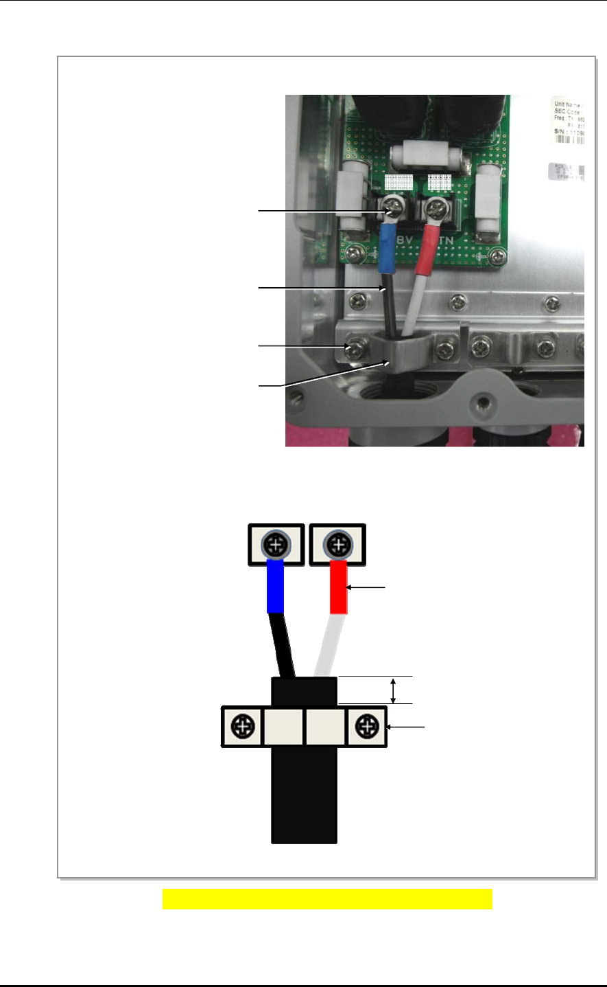
Figure 2.25 Connecting RRH-C2A power cable (AWG8) (4)
Power Terminal Block Fixing Scre
w
RTN-48V
Bracket Fixing Scre
w
(Torque: Max. 5.1 kgf.cm)
Power Cable
(-48V:Black, RTN:White/Black strip)
Power Cable Bracket
RTN-48V
5 mm
Heat Shrink Tube
(-48V:Blue, RTN:Red)
Power Cable Bracket

Smart MBS RRH-P4 Installation Manual/Ver.2.0
© SAMSUNG Electronics Co., Ltd. 2-33
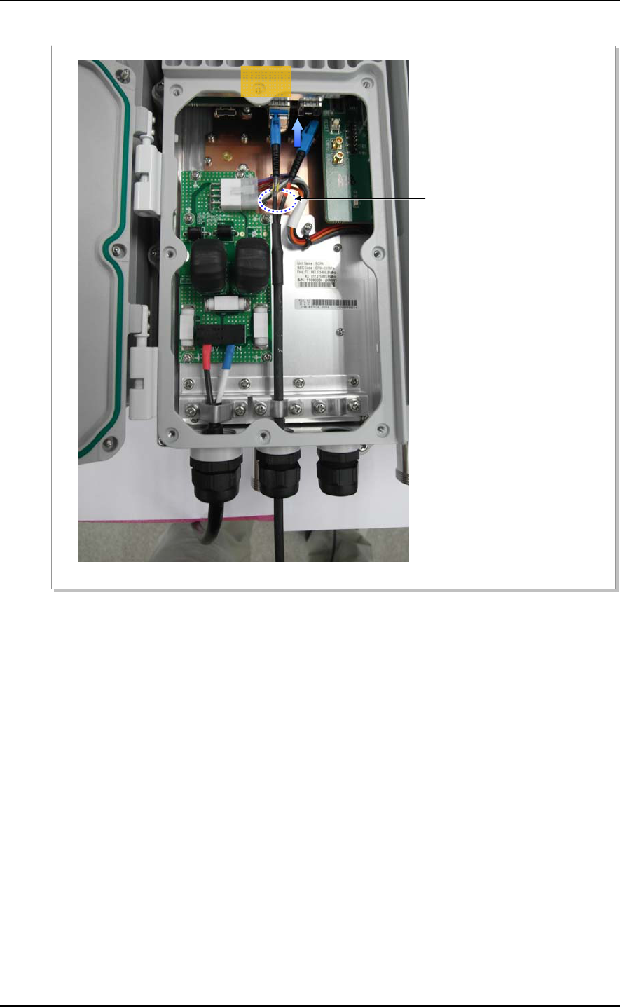
12) When the power cable connection and attachment are complete, close the power
window cover and fix screw (T20) by 12.0 kgf.cm torque.
13) Fix external power cable and external power cable support bracket of the RRH-C2A
with the stainless steel tie.
Installing the Circuit Breaker
To ensure stability in power supply, a circuit breaker must be installed on the
power cable connected to the rectifier (or power distributor).
Capacity of -48 VDC circuit breaker is 32 A.
CHAPTER 2. Installation of RRH-C2A
2-34 © SAMSUNG Electronics Co., Ltd.
2.7.4 Connecting RRH-C2A CPRI cable
Follow the steps below to connect the CPRI cable for the interface between RRH-C2A and
UADU.
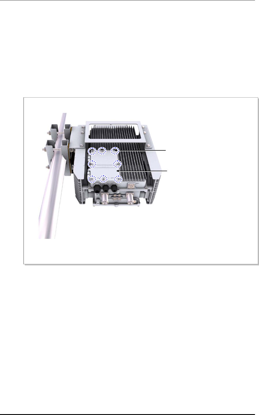
1) Unscrew the optic window cover fixing screw located at the front bottom of RRH-C2A
using a Torx (T20) screwdriver. (The cover fixing screw is designed to remain attached to
the cover.)
Figure 2.34 Connecting RRH-C2A CPRI cable (1)
Cover Fixing Screw(T20)
Install Window Cover

Smart MBS RRH-P4 Installation Manual/Ver.2.0
© SAMSUNG Electronics Co., Ltd. 2-35
2) Remove the cable gland nut and rain protection sponge from the optic cable input hole
located at the bottom of the equipment.
3) Insert the cable gland nut and the rain protection sponge to the optic cable in
respective order.
4) Insert the optic cable (5 core, 1 pc) from the bottom of the equipment through the optic
cable input hole, then bury within the optic window. Insert the optic connector to the
SFP module.
(Maintain the optic cable’s minimum bending radius of R=20 mm to preserve the
cable performance and prevent damage.)
5) When the connection of the optic connector is complete, allow approx. 10 mm of the
optic cable’s sheath in the box, insert the rain protection sponge in the gland hole, then
fasten the cable gland nut by torque 40.8 kgf.cm.
6) When the CPRI cable connection is complete, close the window cover and fasten the
screw by torque: 12.0 kgf.cm.
CHAPTER 2. Installation of RRH-C2A
2-36 © SAMSUNG Electronics Co., Ltd.
Figure 2.35 Connecting RRH-C2A CPRI cable (2)
Table 2.5 CPRI Cable connection configuration
Cable Color Blue Orange Green Brown Gray
Port Optic 0 (LTE 0) Optic 1 (CDMA 0) Spare Spare Spare
Optic Cable
(Single Mode)
Optic1
(CDMA0)
Smart MBS RRH-P4 Installation Manual/Ver.2.0
© SAMSUNG Electronics Co., Ltd. 2-37
Cautions When Connecting the CRPI Cable
Failure to observe the CPRI cable connection specified in Table 2.5 may impair
the communication between the CDMA terminal.
Caution for Laser Beam of Optical Module and Cable
The optical module and cable used in the system emit bright laser beams.
Always handle them with care as there is risk of serious injury if the eyes are
exposed to the laser beam of the optical cable.
RRH-C2A optic cable connection standard
Cable connection standard between UADU CPRI port and RRH-C2A optic port is
different according to the count(One or two) of CDMA UADU(Installed in DU
cabinet).
Connect the optic cable(Refer to the connection standard of 'table 2.6' and 'table
2.7'). Because false connection can cause the fault of call connection, be
cautious.
CHAPTER 2. Installation of RRH-C2A
2-38 © SAMSUNG Electronics Co., Ltd.
RRH-C2A Optic Cable
The optic cable consists of 5 cores. The grey cable is the spare cable for
replacement in case one of the 4-core optic cables would fail.
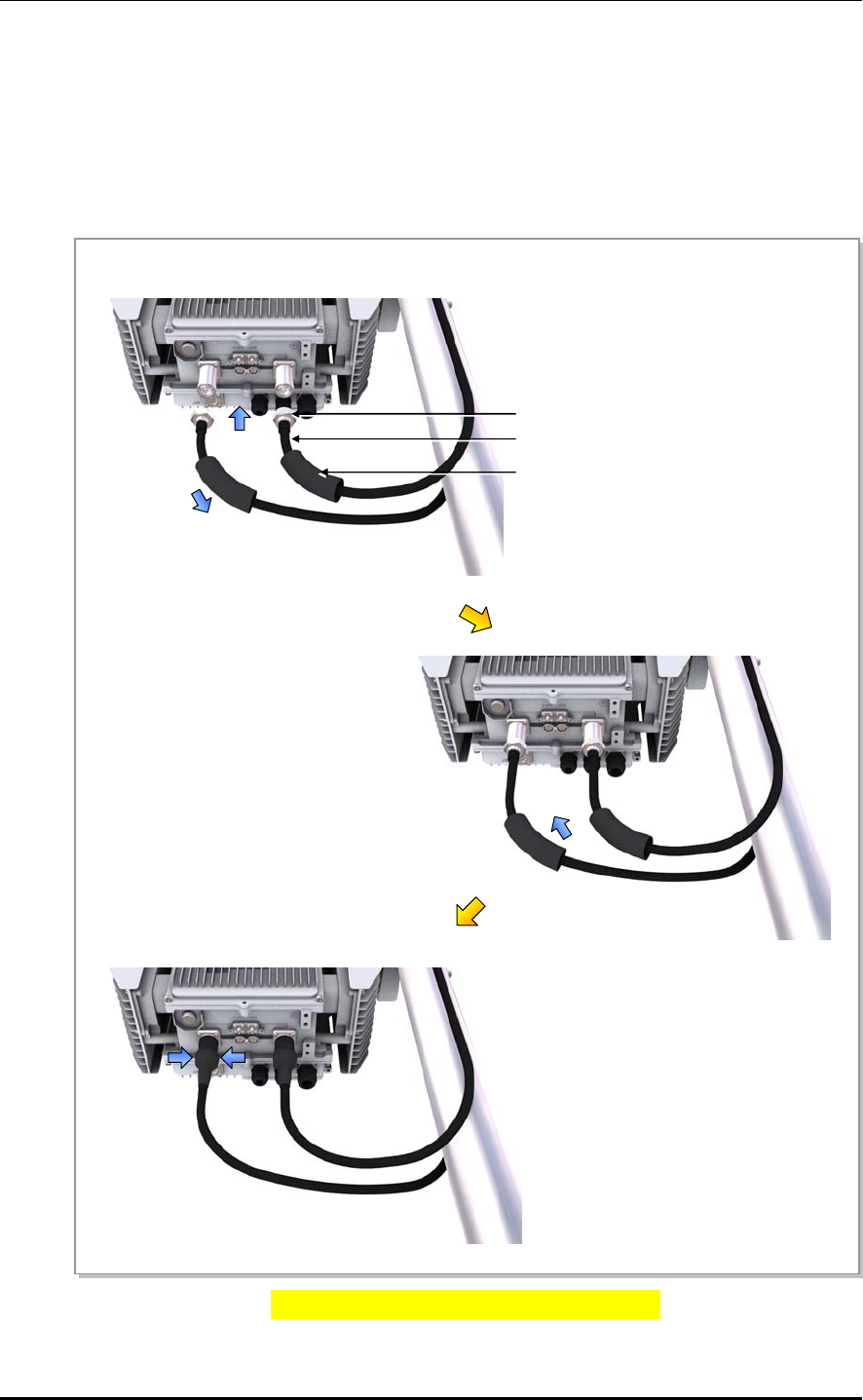
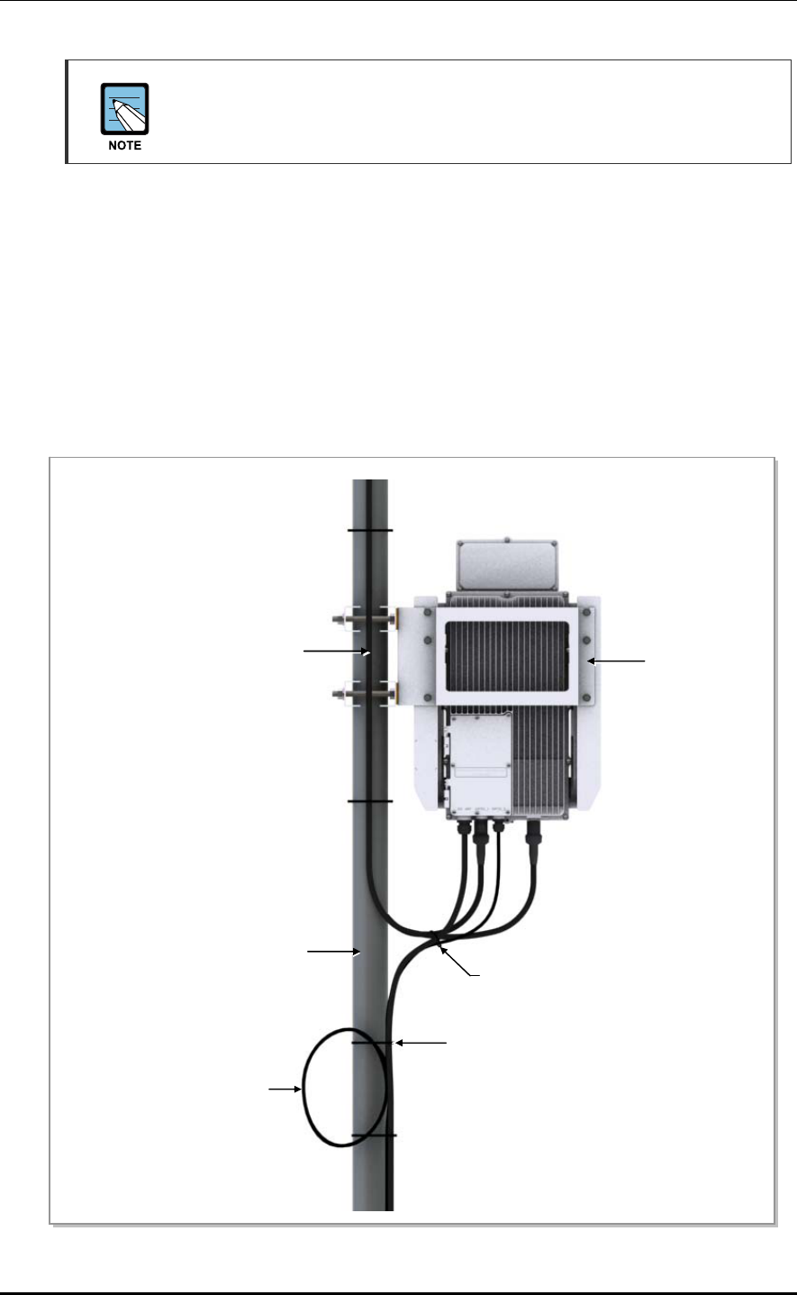
2.7.5 Remaining length of Hybrid cable
Follow the steps below to organize the remaining length of the cable after connecting the
hybrid cable (power cable, CPRI cable) to RRH-C2A.
1) Loop the excess length of the power cable and CPRI cable, and attach to the RRH-
C2A fixing pole using a cable tie. Ensure to respect the optic cable’s bending radius of
(R=110 mm).
2) Bind the power cable and CPRI cable together with the feeder line using a cable tie.
Figure 2.36 Remaining length of Hybrid cable (1)
Cable Tie
Feeder Line RRH-C2A
RRH-C2A Fixing Pole
Remaining length of cable
Cable Tie
Cable Tie
Smart MBS RRH-P4 Installation Manual/Ver.2.0
© SAMSUNG Electronics Co., Ltd. 2-39
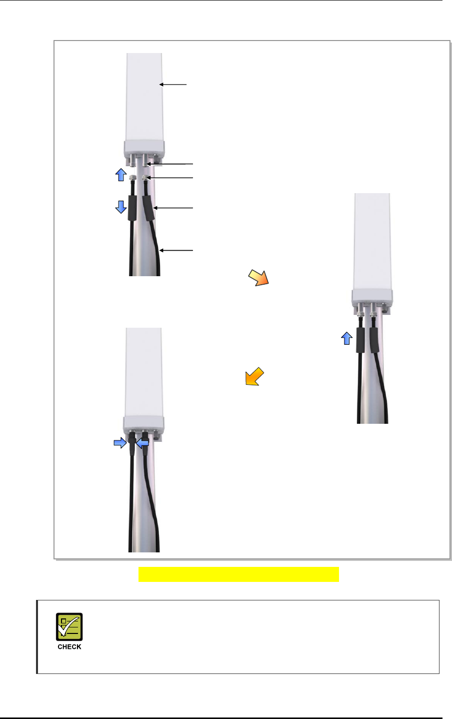
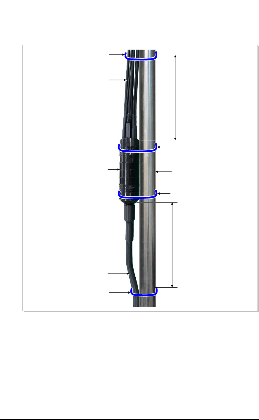
3) Attach the junction box (breakout point) to the pole using a stainless steel band.
Tie the cables to the pole 500 mm below and 500 mm above the box.
(To stabilize the cables near the junction box’s cable input and output holes.)
Figure 2.37 Remaining length of Hybrid cable (2)
Pole
Junction Box
(Breakout Point)
Hybrid Cable
(from. DU Cabinet)
Power & Optic Cable
(to. RRH-C2A)
Cable Tie
Stainless steel Band
500 mm
Cable Tie
500 mm
Stainless steel Band
CHAPTER 2. Installation of RRH-C2A
2-40 © SAMSUNG Electronics Co., Ltd.
4) Bind the spare cable to the pole with its waterproof cap facing up. Loop the cable’s
remaining length and bind it to the pole below the cap.
Figure 2.38 Remaining length of Hybrid cable (3)
Pole
Water proof Cap
Cable 여장
Cable Tie
Cable Tie

Smart MBS RRH-P4 Installation Manual/Ver.2.0
© SAMSUNG Electronics Co., Ltd. 2-41
2.8 Installation Test
If the installation of the system is complete, progress the installation test to check the status
of the system. The purpose of this test is to remove problems, which may generate after the
service starts, in advance for stable operation of the system. If there is any problem, restore
the system and write out the failure table.
The installation test should be progressed in the order of power section test and function test.
Power Section Test
The power section test is progressed as follows:
1) Execute the 'off' of the breaker(RRH-C2A power in the DU cabinet is connected).
Make sure that the DC resistance between the -48V/RTN is over tens of kilo ohm
(kΩ).
2) Make sure that the DC resistance between the RTN of Terminal block-① and RRH-
C2A frame is no greater than 10 Ω. The ground cable must be installed at DU cabinet
and RRH-C2A
3) Execute the 'on' of the breaker(RRH-C2A power in the DU cabinet is connected).
Make sure that the voltage between the RTN of terminal block-①, ② is over -
38VDC.
4) Execute the 'on' of the breaker(RRH-C2A power in the DU cabinet is connected).
Verify that the LED(Red or green) in the RRH-C2A installation window is lit.
5) Fasten the cover fixing screw (T20) using a Torque 12.0 kgf.cm. Close the power
window cover and the optic window cover.

CHAPTER 2. Installation of RRH-C2A
2-42 © SAMSUNG Electronics Co., Ltd.
Table 2.8 Construction Status Checklist
Category Check Items Criteria Result Remarks
Pass Fail
System
Installation
System fixing status
(Vertical and horizontal)
Horizontal and vertical
locations
System arrangement
status
Horizontal and vertical
locations
Locking status and
standard compatibility of
bolts/nuts/washers
Visual inspection and magnet
test
External wiring and other
wirings
Visual inspection for twist,
array and arrangement
System cable installation
status
Checking twist, distortion and
installation status
External connector
connection
Visual inspection to check
poor contact
(Tightening status)
Other appurtenant work
(Cable duct installation
and others)
Visual inspection
Power
Acceptance
Equipment’s power
cable specification
Visual inspection
Rectifier ↔ System Visual inspection
Cabling Status Visual inspection for twisted
or entangled status
Damage of cable sheath Visual inspection
System power connector - Visual inspection to check
whether the power
connector is connected
normally without separation.
- Inspection for the power
connector shaking status
System input voltage
(BATT voltage)
Measurement by digital meter
(voltmeter)
External
interface
Optic Cabling Status Visual inspection
Ground
Construction
Ground line standard Visual inspection
Ground bar ↔ System Visual inspection
Ground line cabling
status
Cabling status check
Termination treatment of
the ground line
(Pressure Terminal)
Visual inspection
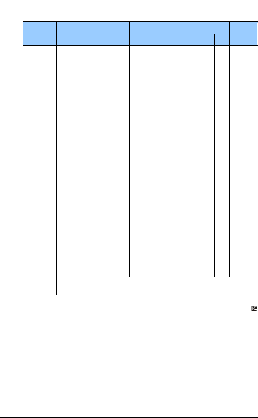
Smart MBS RRH-P4 Installation Manual/Ver.2.0
© SAMSUNG Electronics Co., Ltd. 2-43
Table 2.8 Construction Status Checklist (continued)
Category Check Items Criteria Result Remarks
Pass Fail
Feeder
Line status
Feeder Line installation and
fixing status
View, consistency,
bending
ANT installation and
connection status
Visual inspection
(ANT stick shaking status)
Connection and end
processing status
View, consistency
Various
TAG Status
Feeder Line tag Visual inspection
(Content: Length, LOSS
value, position)
Power cable tag Visual inspection
Ground table tag Visual inspection
Attachment status of the
label for the real-name
construction system
- Indoor: wall side of the gate
side
- Outdoor: inside of the
cover of the distribution box
Visual inspection
(size, material, etc.)
Cable duct, bolt connection
status
Visual inspection
Feeder line Entrance end
processing status (Outdoor)
Visual inspection
(Checking back side
Connection)
Status of inside/outside of
the system and vicinity of the
base station
Visual inspection
General
Opinion

Smart MBS RRH-P4 Installation Manual
© SAMSUNG Electronics Co., Ltd. A-1
ANNEX A. Sector Antenna Installation
A.1 Cautions when Installing a Sector Antenna
Precautions of antenna installation are as follows.
Sector antennas should be installed vertically. (±1)
Antenna is the precise material, so be careful not to make damage or form change.
When moving antenna, use the tool suitable to rating. In addition, use the rated
carrying device which is at least 200% or more than antenna considering the stability.
Be careful not to give too much strength to the antenna.
If it rains, suspend connecting the feeder cable and antenna.
Fix it after adjusting the direction of antenna exactly.
Distance between steel tower and antenna and the distance between send-receive
antennas are based on the antenna layout.
Attach the antenna on the position specified in the drawing.
Install the antenna not to make a feature change of the antenna considering the
direction of the radiation
When connect the connector to the antenna, not making the alien substance flowed and
is not under the influence of PIMD.
Measure VSWR of all antennas and the value should be within the regulated value.
A.2 Sector Antenna Layout
The method of sector antenna layout is as follows.
1) Use the transit to adjust the antenna installation direction exactly.
2) Fix the direction of the sector antenna, same as the angle settled when designing the
cell after installing the steel tower.
3) Arrange the antennas of each sector to the sector directional angle at right angles by
adjusting the distance between antenna and steel tower.
In the event of the station whose the direction between sectors is not 120°, install it to
make the steel tower and antenna direction different being careful of the tilt and
azimuth.
4) For circular platform, separate the antenna interval at maximum.
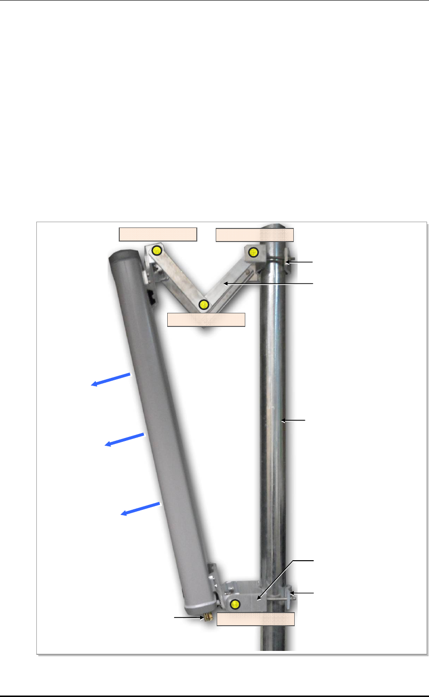
ANNEX A. Sector Antenna Installation
A-2 © SAMSUNG Electronics Co., Ltd.
A.3 Sector Antenna Installation
The method of sector antenna installation is as follows.
1) Put up an antenna pole and insert the sector antenna into the antenna pole using a
fixing clamp.
2) Set the antenna’s up/down tilt to 0° and fix the fixing clamps at the top and bottom.
3) After tightening the fixing clamp, adjust the antenna up/down (tilt) depending on the
signal strength. The bolt of the guide clamp must be loosened, so the antenna angle can
be adjusted.
4) After setting the antenna angle, fasten the bolt of the guide clamp, which was loosened
previously. Regarding the nut, the double nut mounting should be used to prevent the
nut from coming loose.
Figure A.1 Sector Antenna
Antenna Input Port
Pole
Main Radiation Direction
Upper Fixing Clamp
Lower Fixing Clamp
Upper Guide Clamp
Lower Guide Clamp
Guide Clamp Bolt_2
Guide Clamp Bolt_1
Guide Clamp Bolt_3
Guide Clamp Bolt_4


MPE Information
ⓒ SAMSUNG Electronics Co., Ltd.
Warning: Exposure to Radio Frequency Radiation The radiated output power
of this device is far below the FCC radio frequency exposure limits.
Nevertheless, the device should be used in such a manner that the potential
for human contact during normal operation is minimized. In order to avoid
the possibility of exceeding the FCC radio frequency exposure limits, human
proximity to the antenna should not be less than 500cm during normal
operation. The gain of the antenna is 14 dBi. The antenna(s) used for this
transmitter must not be co-located or operating in conjunction with any other
antenna or transmitter.