Samsung Electronics Co SMM-BMAA022000 Smart MBS (Smart Multi-modal Base Station) User Manual
Samsung Electronics Co Ltd Smart MBS (Smart Multi-modal Base Station)
UserManual.wiki
>
Samsung Electronics Co
>
SMM BMAA022000 User Manual
User Manual
Navigation menu
Upload a User Manual
Namespaces
Wiki Guide
HTML
PDF
Info
Views
User Manual
Discussion / Help
Navigation
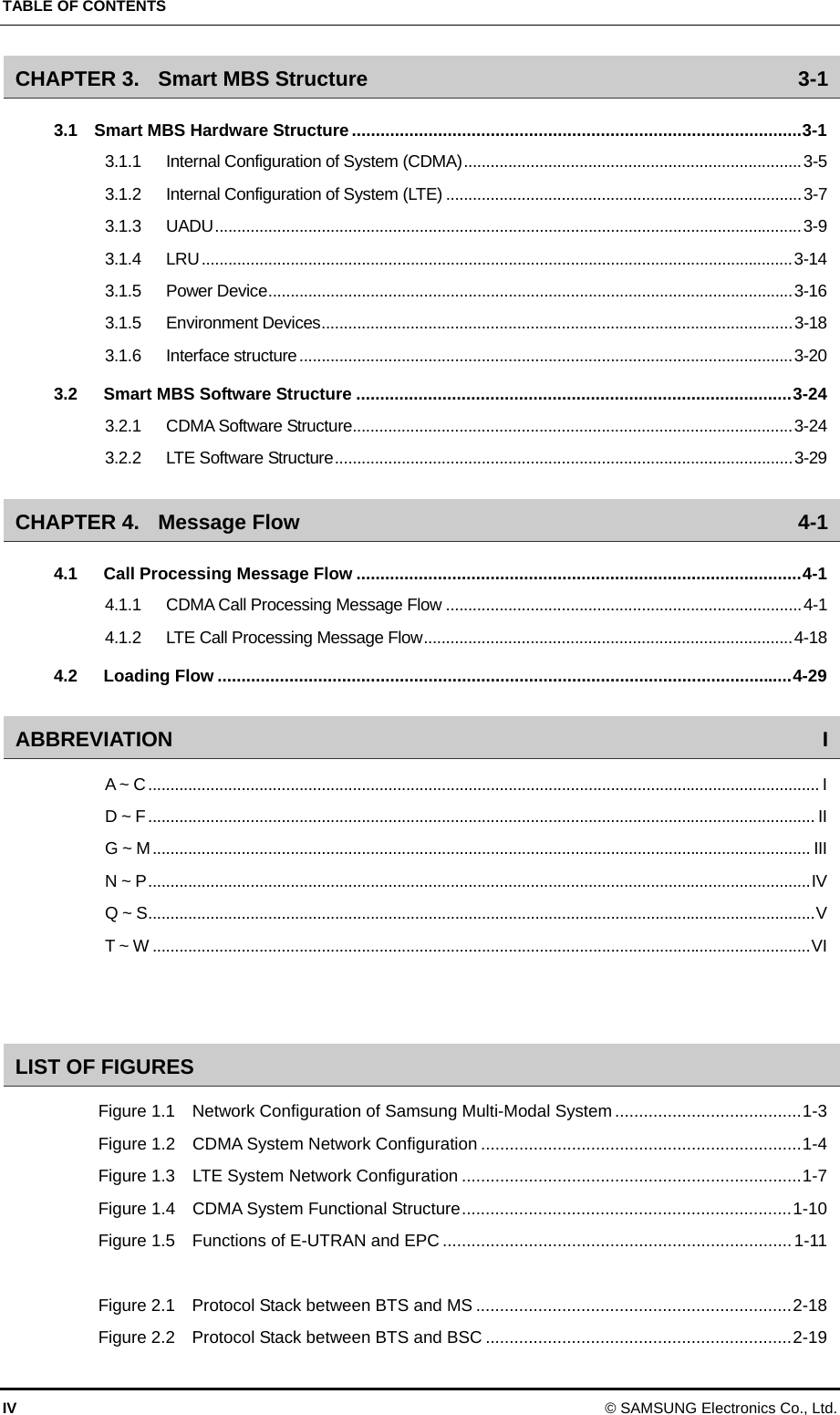
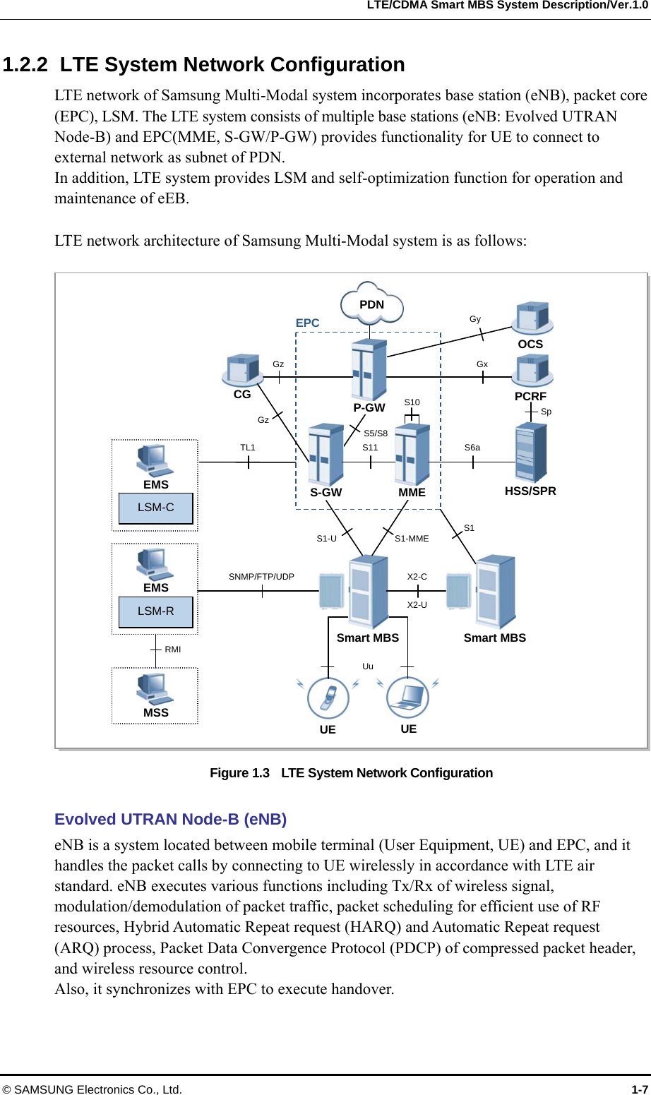
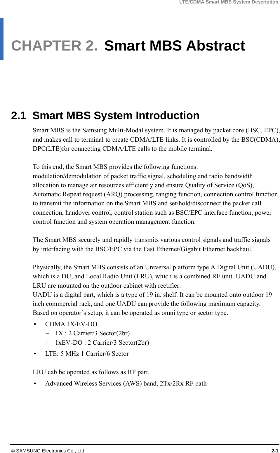


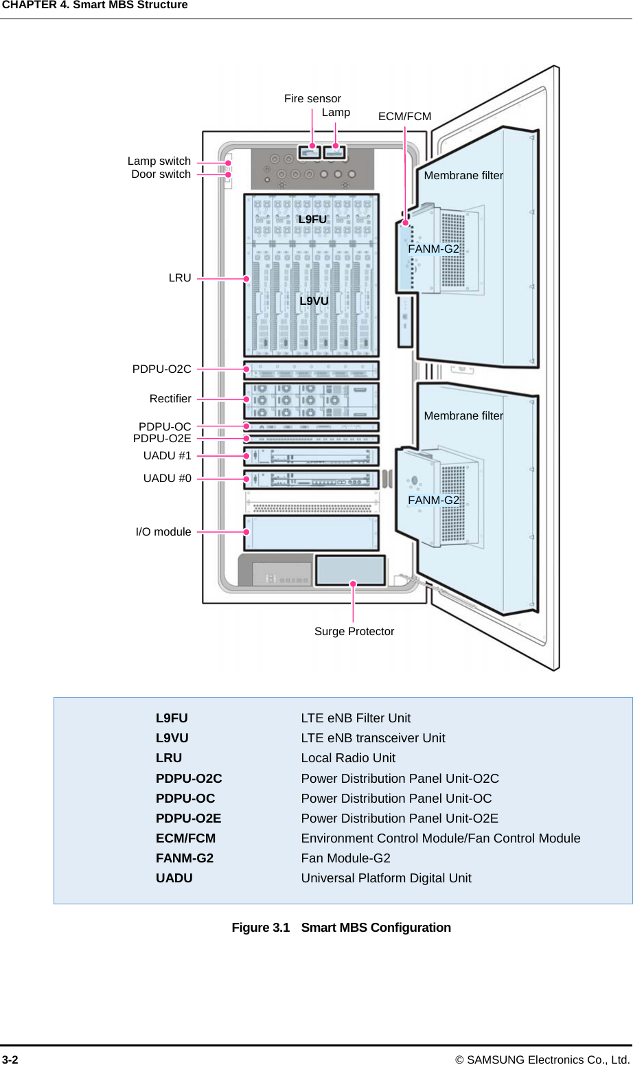
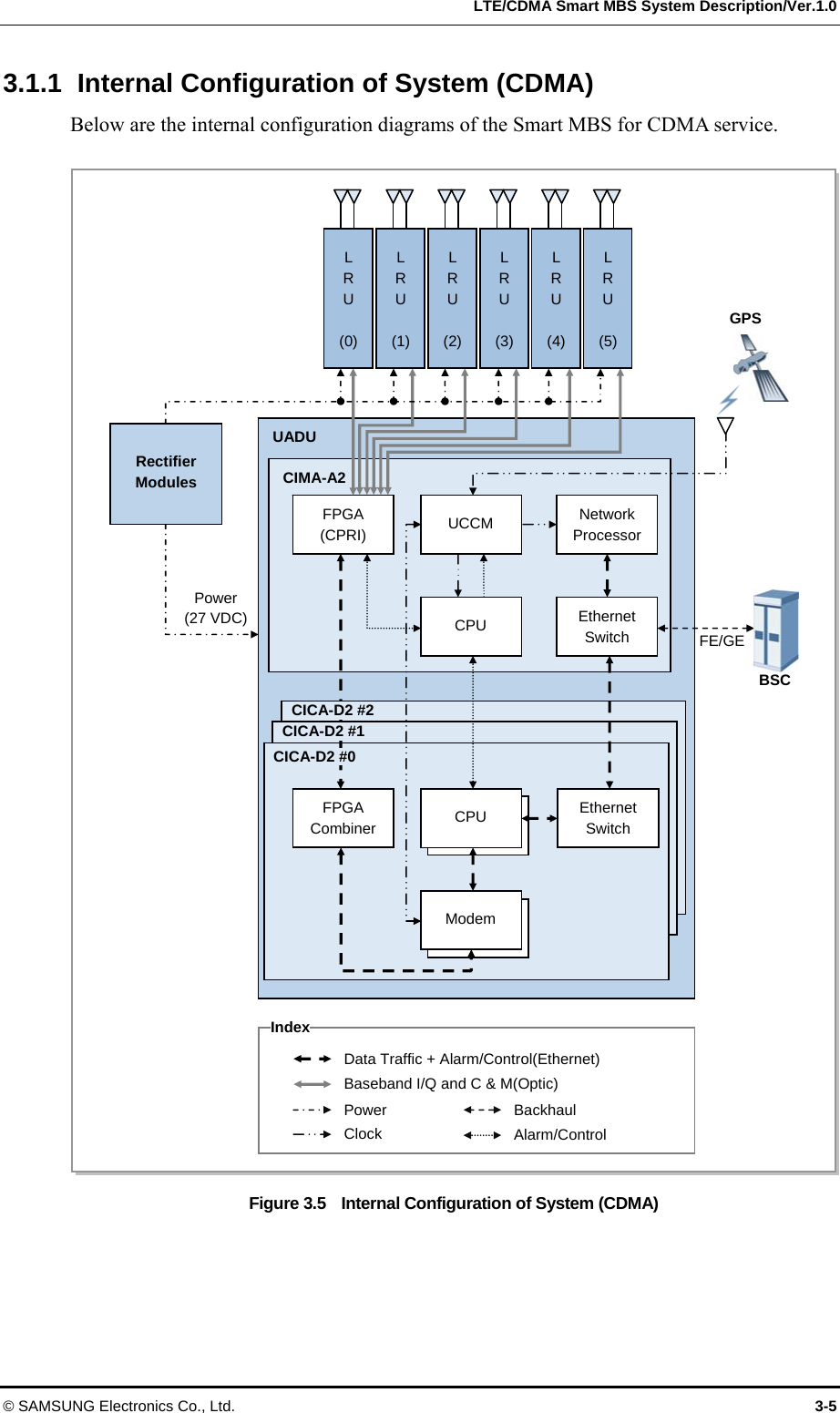
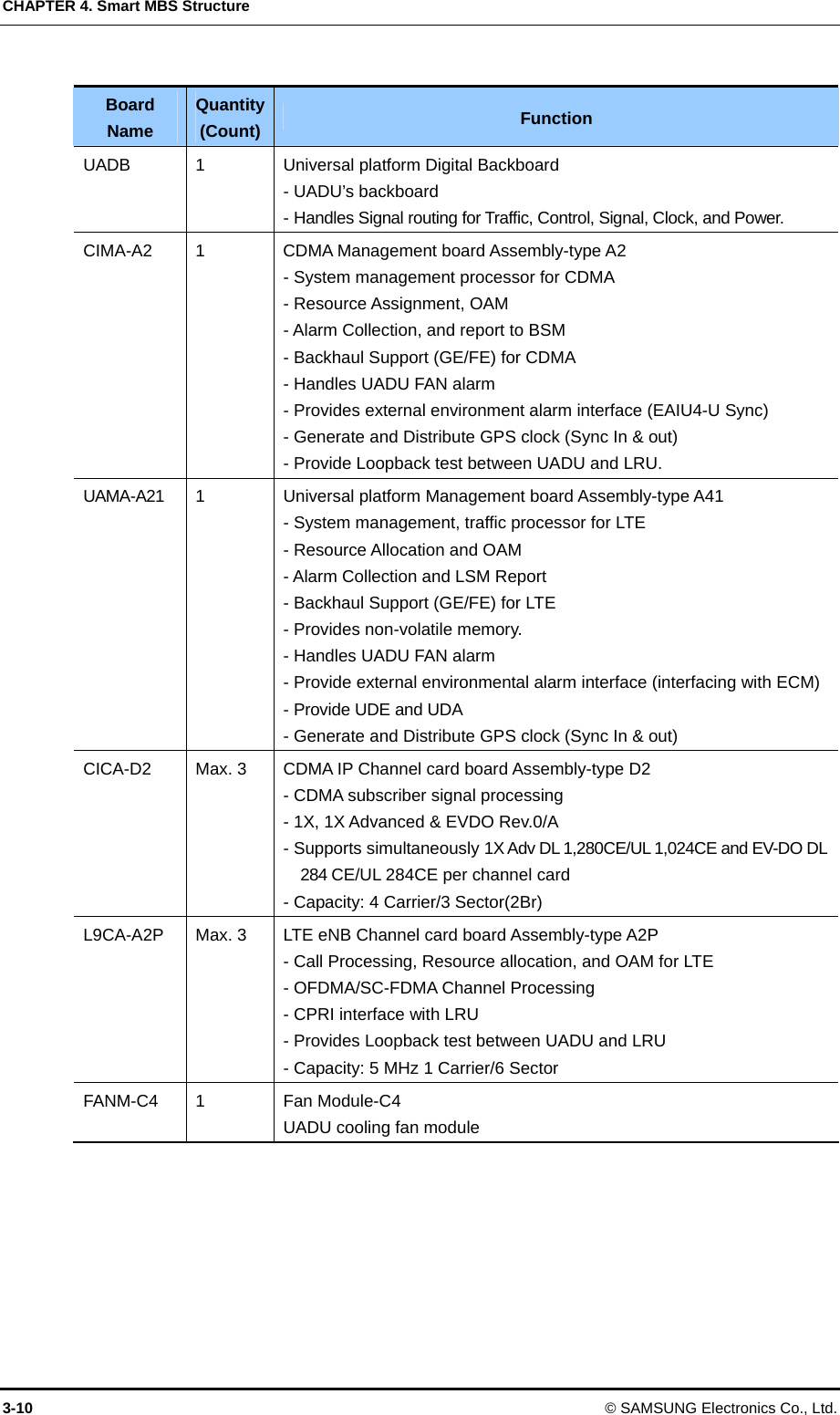
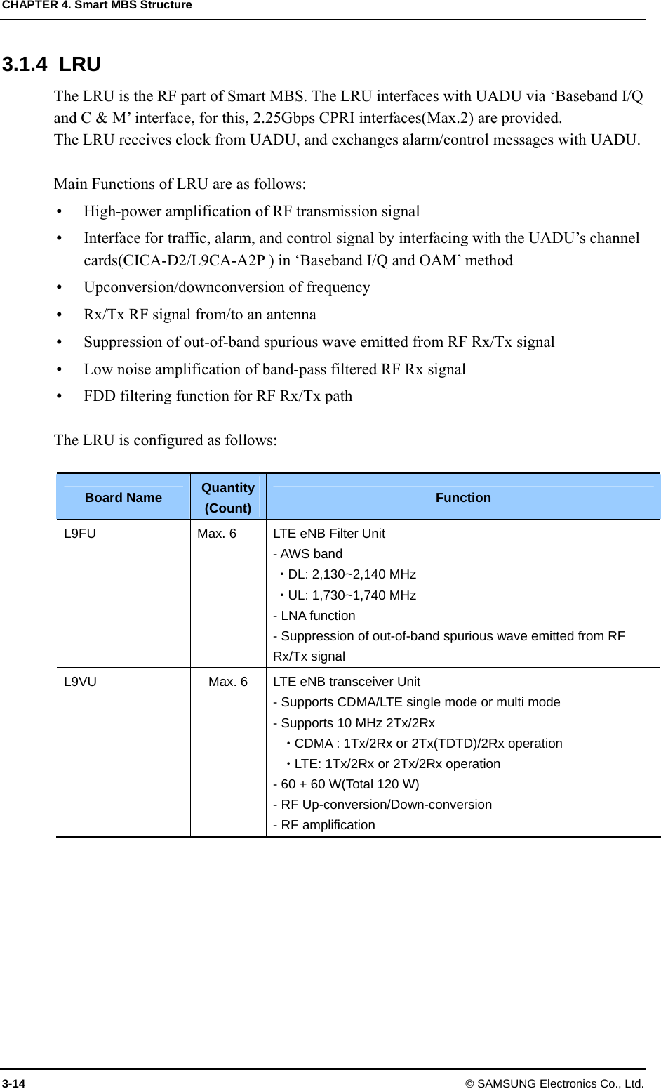
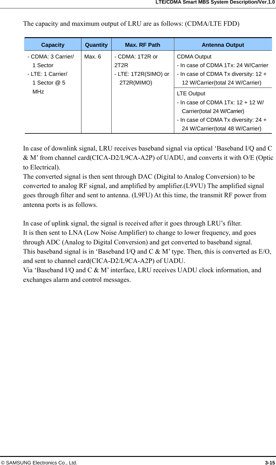
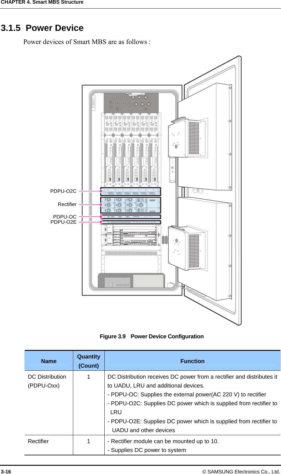
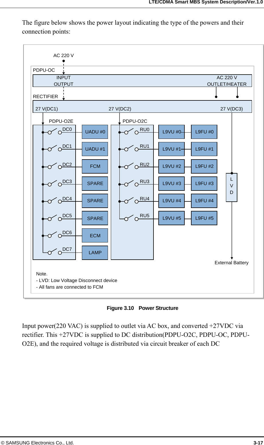
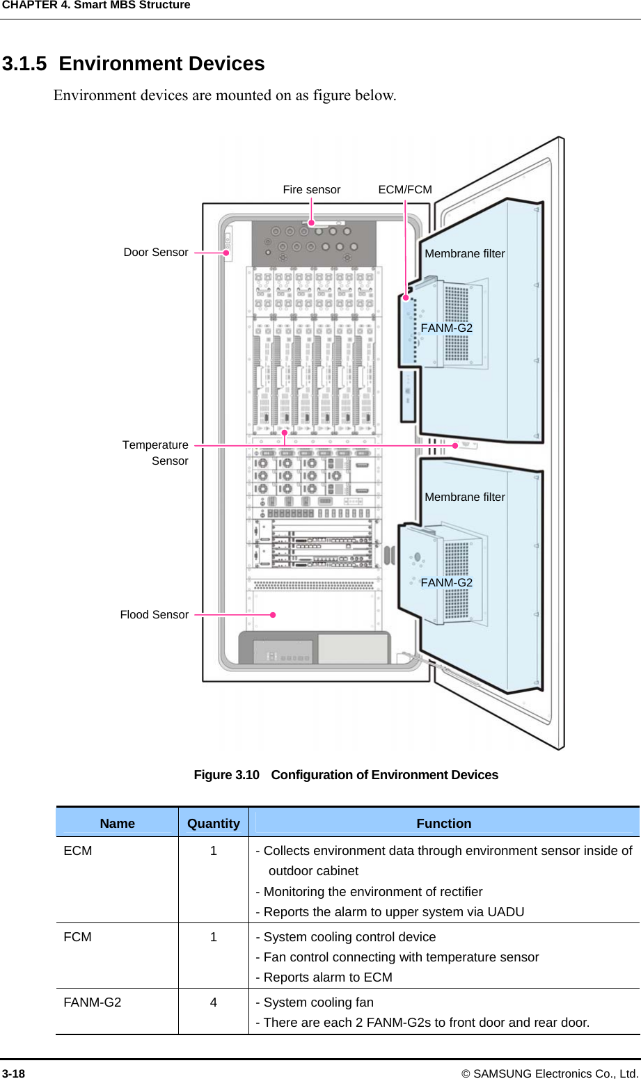
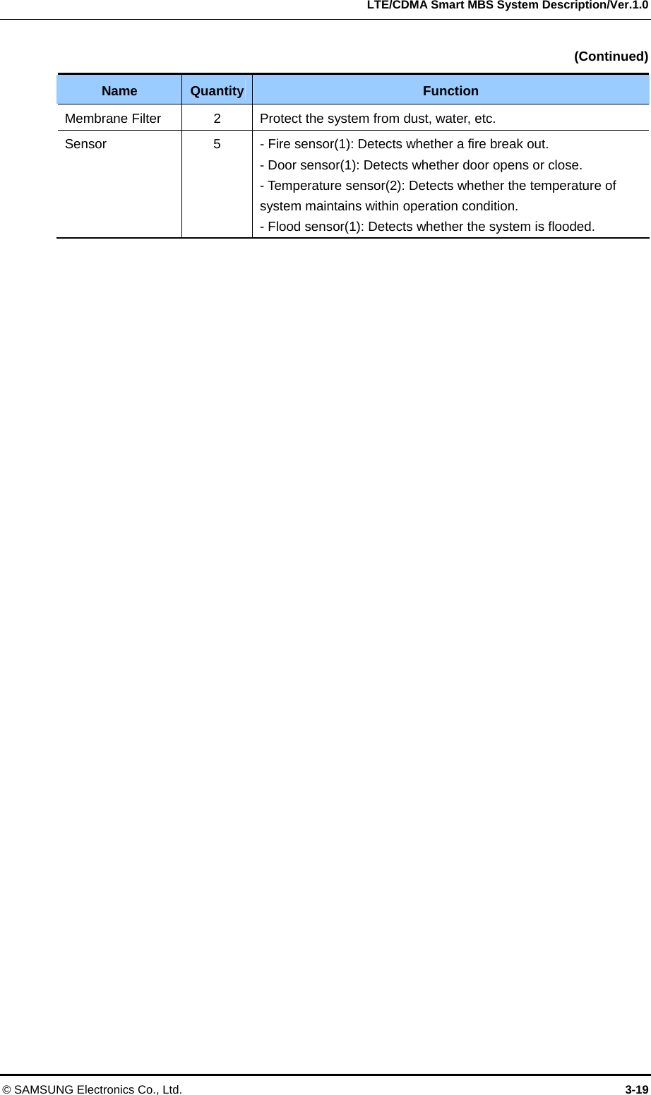
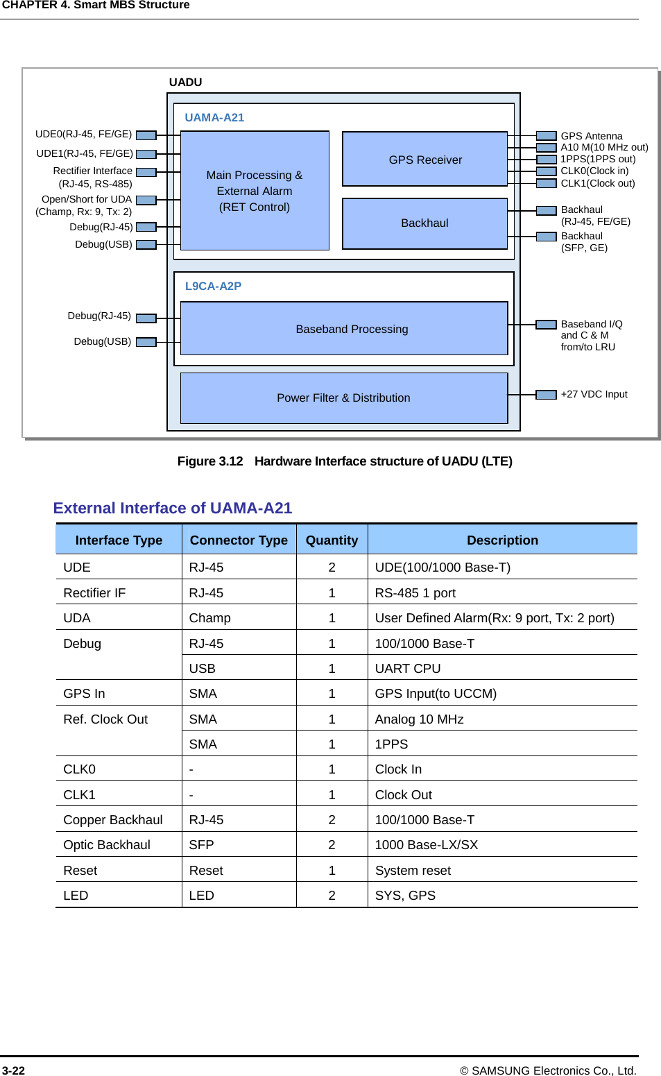
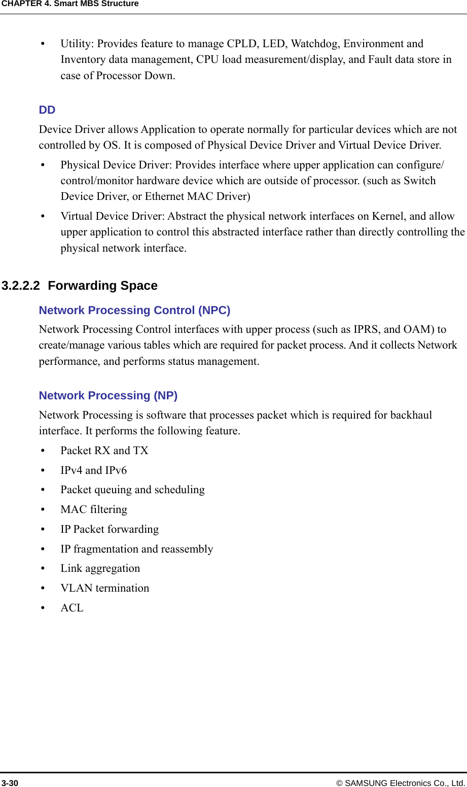
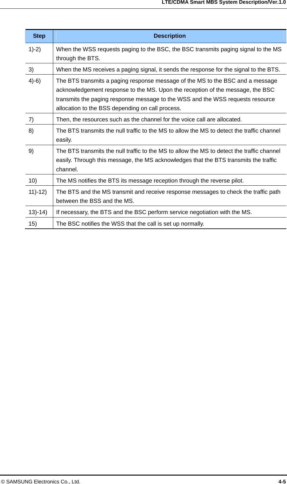
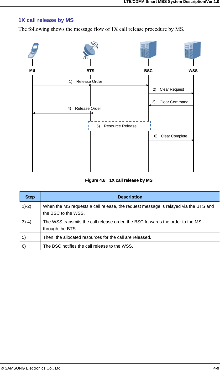
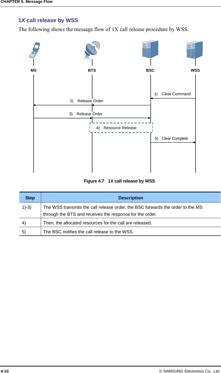
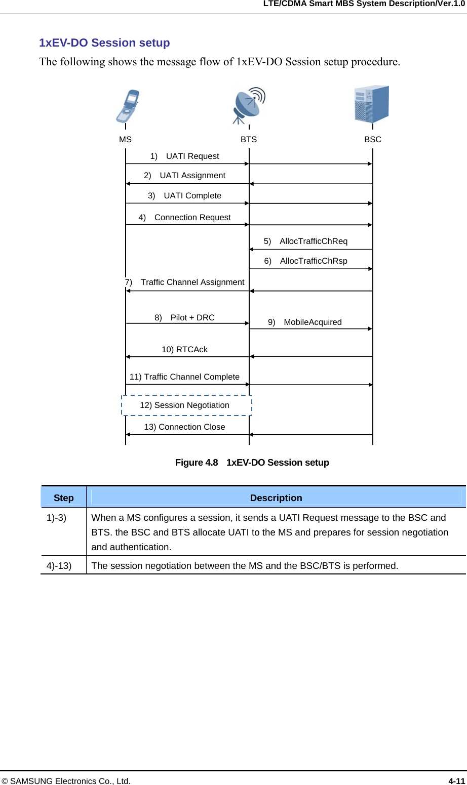
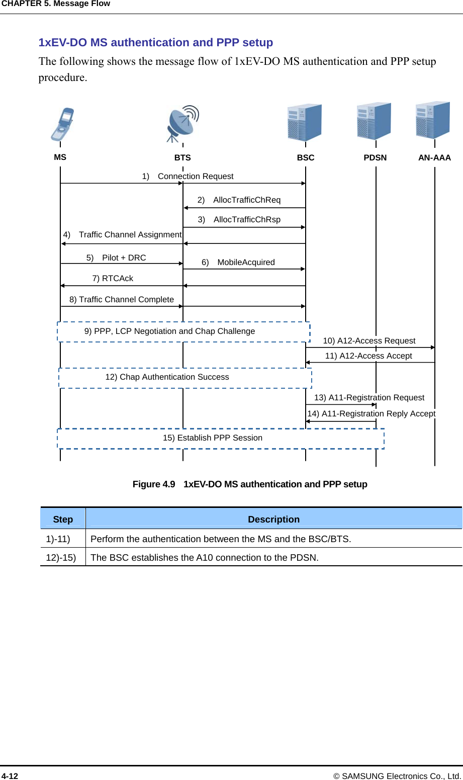
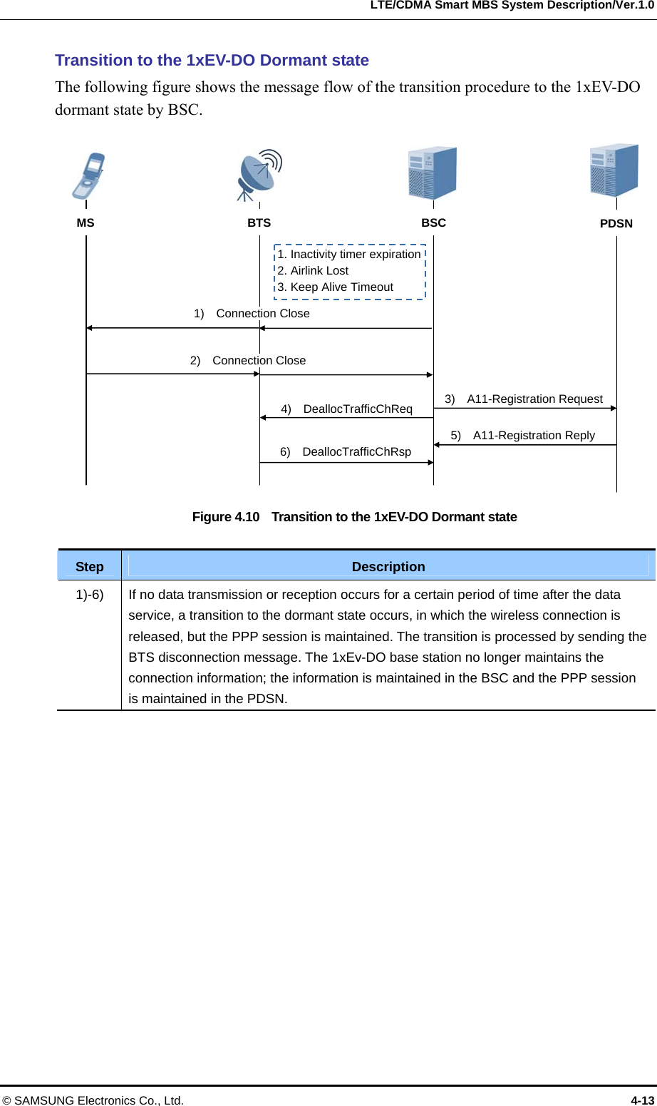
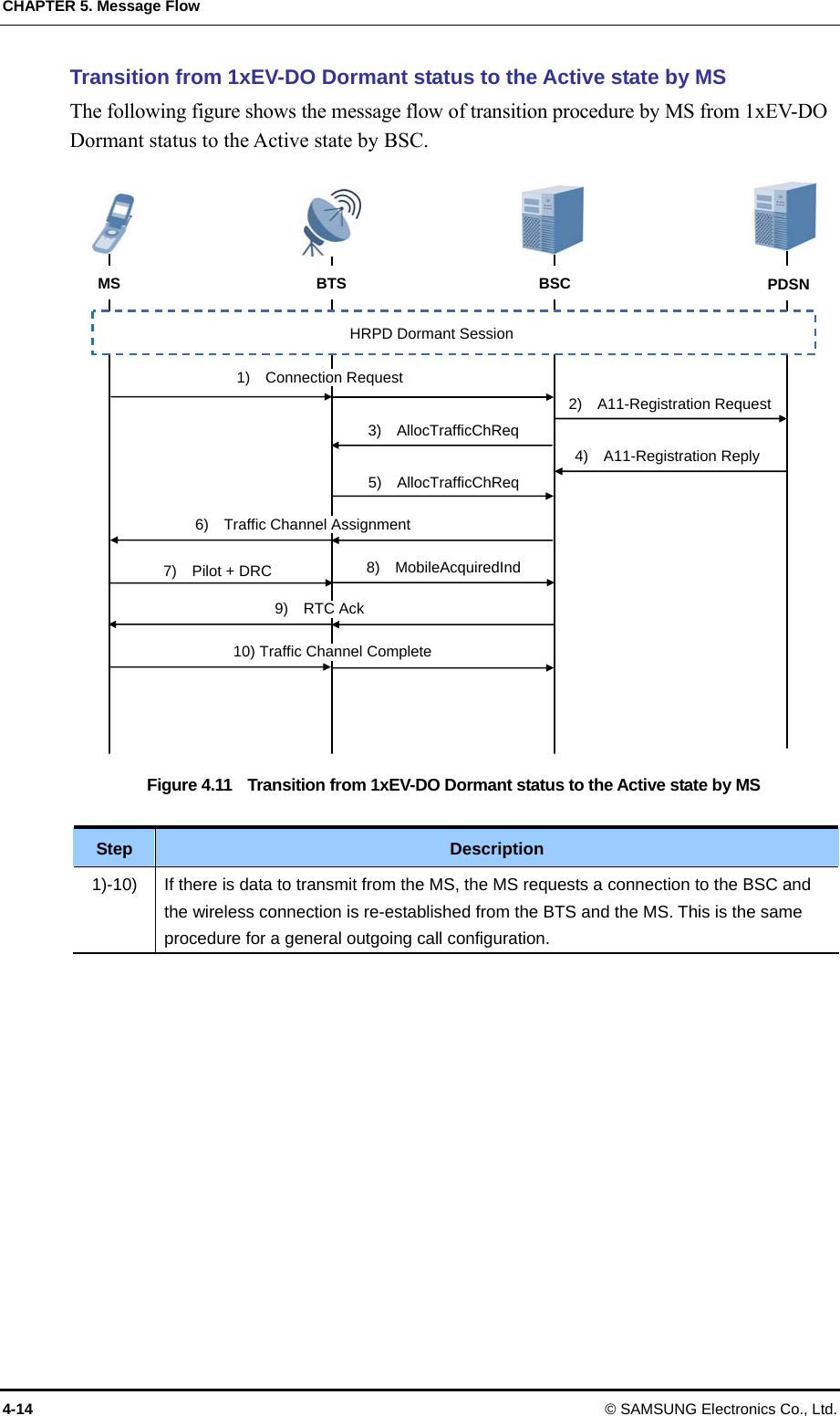
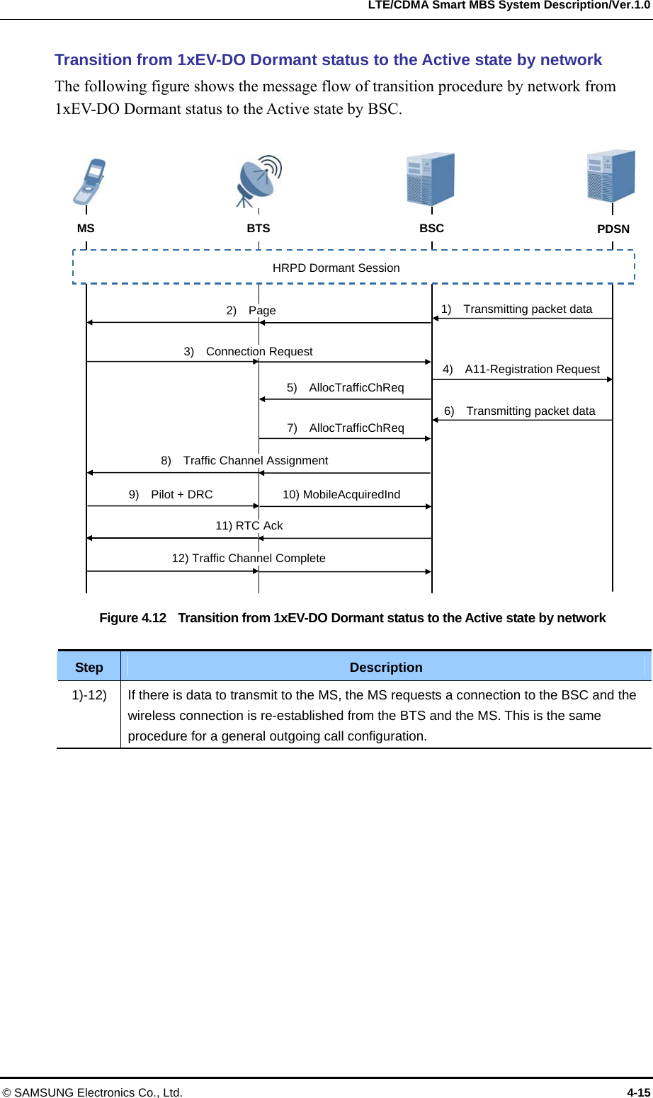
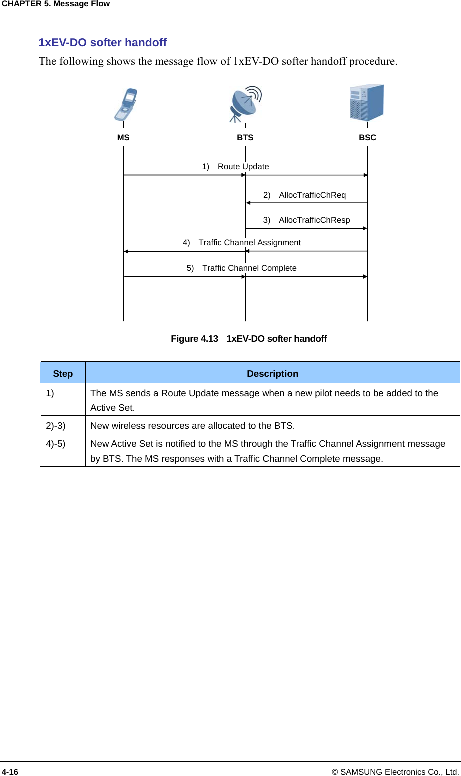
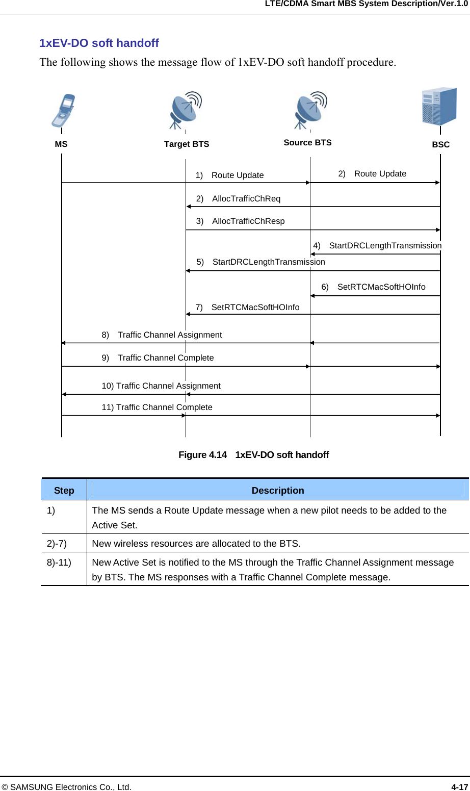
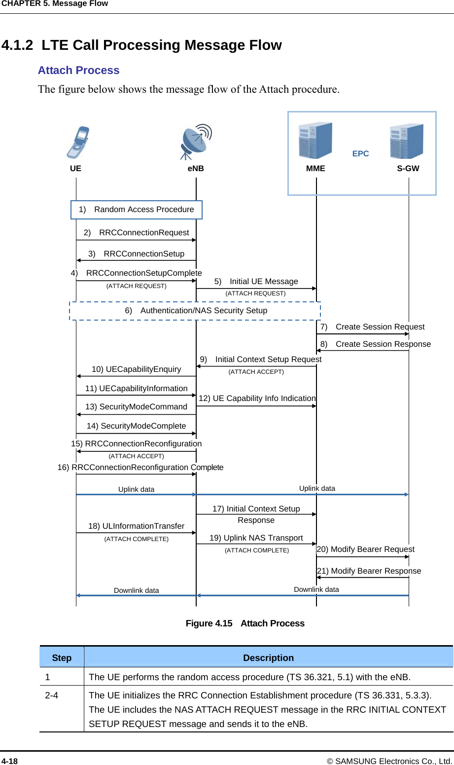
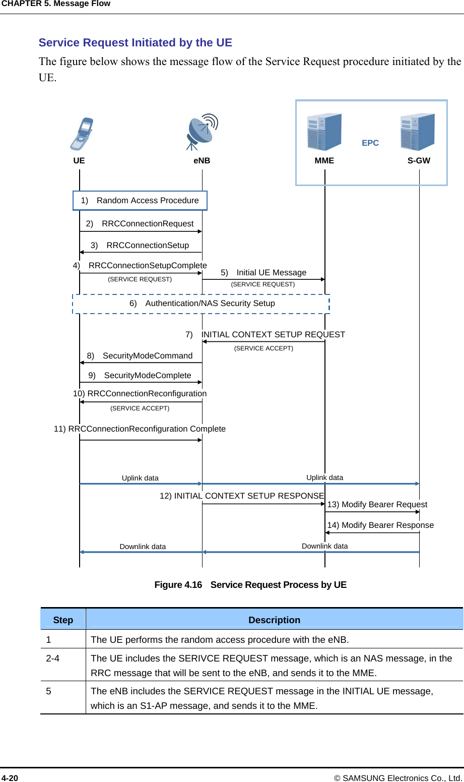
![LTE/CDMA Smart MBS System Description/Ver.1.0 © SAMSUNG Electronics Co., Ltd. 3-9 3.1.3 UADU UADU provides OAM for Smart MBS, interworking with BSC(CDMA)/EPC(LTE)/LRU, and communication paths between various functional blocks within the system. UADU receives synchronization signal from GPS, creates signals for system synchronization (such as reference clock, Even, SFN, and supply synchronization signals to lower hardware blocks. UADU interfaces with LRU to exchange data/control traffic and also executes signal processing for subscriber signal. UADU can receive alarm from external devices (such as LRU, lower module, rectifier, or battery) and also provide interface/features to control these external devices. On the downlink, UADU receives traffic/control signal from the BSC/EPC, converts into optical signal via ‘Baseband I/Q and C & M’ converter and sends it to the LRU for sending it over the air to the mobile terminal. On the uplink, UADU receives the ‘Baseband I/Q and C & M’ signal from the LRU, demodulates it and sends it to the BSC/EPC. Main functions of UADU are as follows: Baseband Signal processing (Modem) Fast Ethernet/Gigabit Ethernet interface with BSC/EPC Diagnosis, collection, and control of Alarm Alarm Reporting Feature Reference clock generation and distribution Management of Channel Resources Supporting interfacing with the LRU and loopback test Providing UDA and UDE function, and interfacing with external devices Figure 3.7 UADU Configuration FANM -C4 FANM -C4 [CDMA + LTE Multi Mode(Two UADUs)] FANM -C4 [CDMA + LTE Multi Mode] L9CA-A2P CICA-D2 UAMA-A21 CIMA-A2 Blank Blank CICA-D2 CIMA-A2 L9CA-A2P CICA-D2 UAMA-A21 CIMA-A2](https://usermanual.wiki/Samsung-Electronics-Co/SMM-BMAA022000/User-Guide-1688369-Page-57.png)