Samsung Electronics Co SMT515 Tablet User Manual SAMSUNG SM T515 RF Test Report 2G 3G rev01 Part1
Samsung Electronics Co Ltd Tablet SAMSUNG SM T515 RF Test Report 2G 3G rev01 Part1
Contents
- 1. A3LSMT515_User Manual
- 2. SAMSUNG SM-T515 RF Test Report_2G 3G_rev01_Part1
SAMSUNG SM-T515 RF Test Report_2G 3G_rev01_Part1
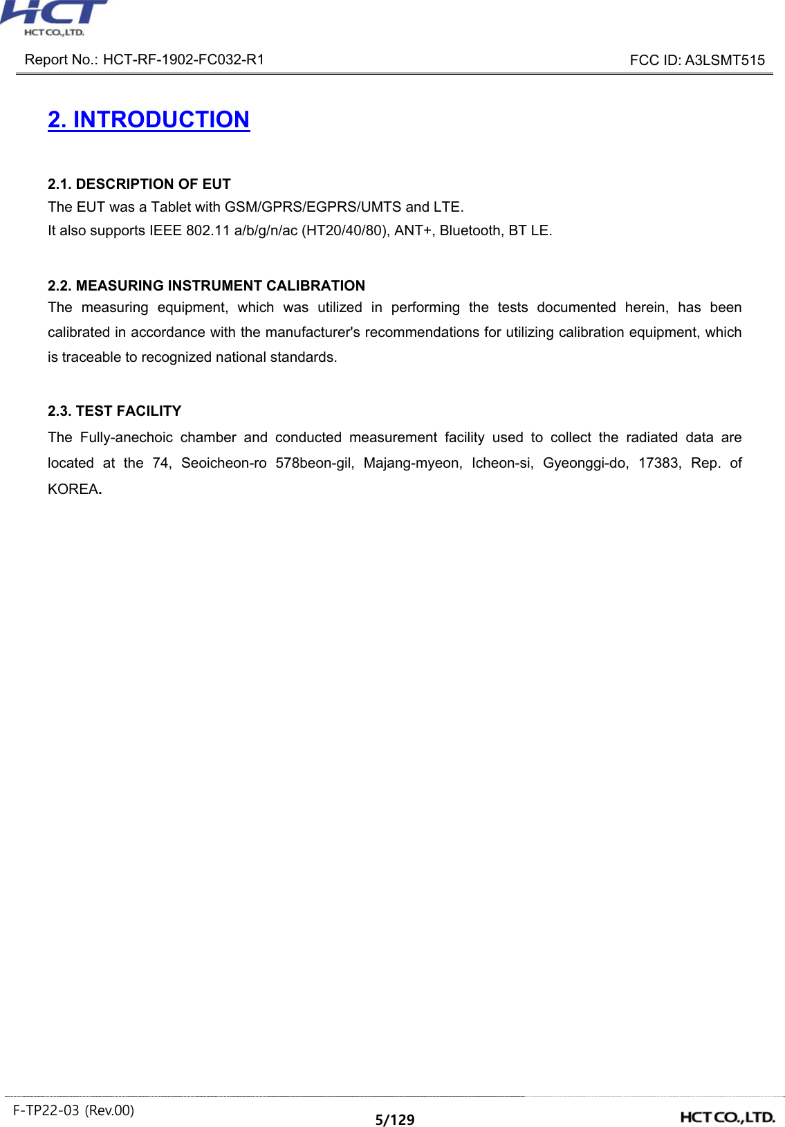
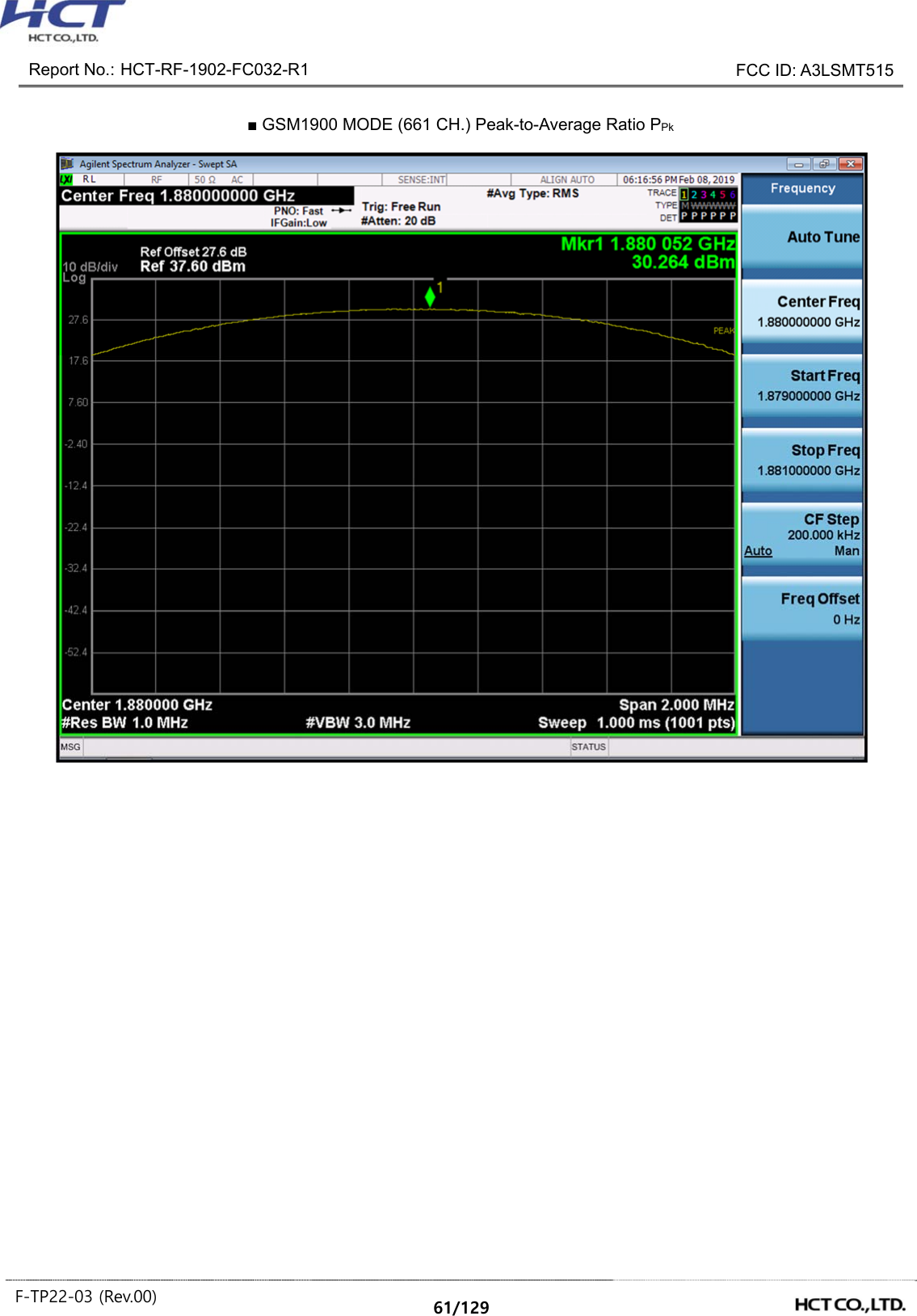
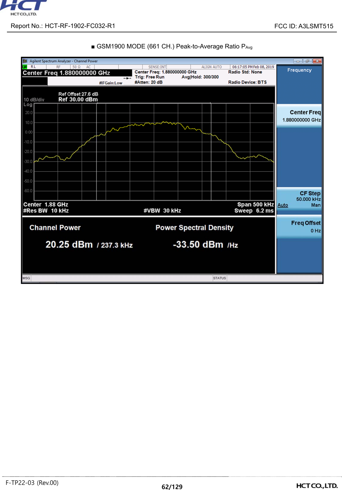
![Report No.: HCT-RF-1902-FC032-R1 FCC ID: A3LSMT515 F-TP22-03 (Rev.00) 10/129 ② Alternate Procedure for PAPR Use one of the procedures presented in 5.2(ANSI C63.26-2015) to measure the total peak power and record as PPk. Use one of the applicable procedures presented 5.2(ANSI C63.26-2015) to measure the total average power and record as PAvg. Determine the P.A.R. from: P.A.R(dB) = PPk (dBm) – PAvg (dBm) (PAvg = Average Power + Duty cycle Factor) Test Settings(Peak Power) The measurement instrument must have a RBW that is greater than or equal to the OBW of the signal to be measured and a VBW ≥ 3 × RBW. 1. Set the RBW ≥ OBW. 2. Set VBW ≥ 3 × RBW. 3. Set span ≥ 2 × OBW. 4. Sweep time ≥ 10 × (number of points in sweep) × (transmission symbol period). 5. Detector = peak. 6. Trace mode = max hold. 7. Allow trace to fully stabilize. 8. Use the peak marker function to determine the peak amplitude level. Test Settings(Average Power) 1. Set span to 2 × to 3 × the OBW. 2. Set RBW ≥ OBW. 3. Set VBW ≥ 3 × RBW. 4. Set number of measurement points in sweep ≥ 2 × span / RBW. 5. Sweep time: Set ≥ [10 × (number of points in sweep) × (transmission period)] for single sweep (automation-compatible) measurement. The transmission period is the (on + off) time. 6. Detector = power averaging (rms). 7. Set sweep trigger to “free run.” 8. Trace average at least 100 traces in power averaging (rms) mode if sweep is set to auto-couple. (To accurately determine the average power over the on and off period of the transmitter, it can be necessary to increase the number of traces to be averaged above 100 or, if using a manually configured sweep time, increase the sweep time.) 9. Use the peak marker function to determine the maximum amplitude level. 10. Add [10 log (1/duty cycle)] to the measured maximum power level to compute the average power during continuous transmission. For example, add [10 log (1/0.25)] = 6 dB if the duty cycle is a constant 25%.](https://usermanual.wiki/Samsung-Electronics-Co/SMT515.SAMSUNG-SM-T515-RF-Test-Report-2G-3G-rev01-Part1/User-Guide-4192744-Page-10.png)
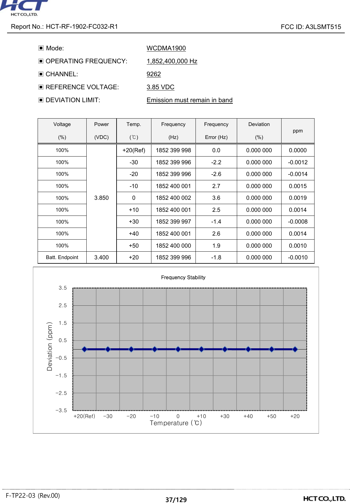
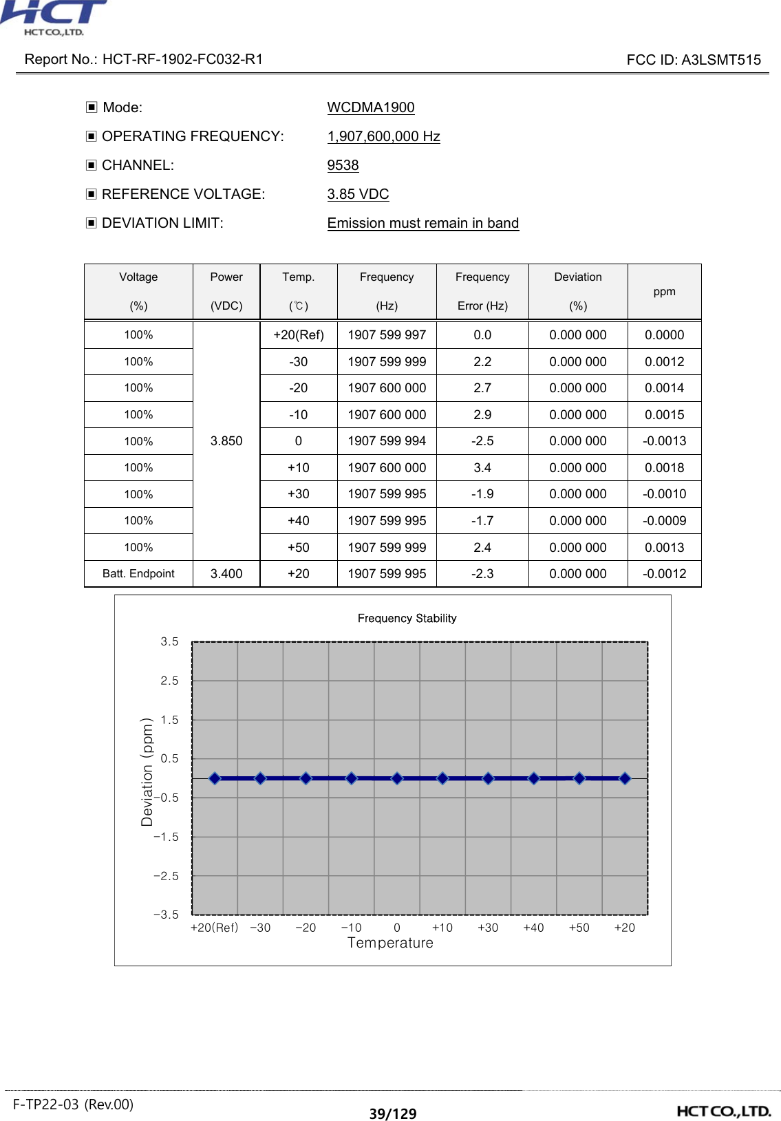
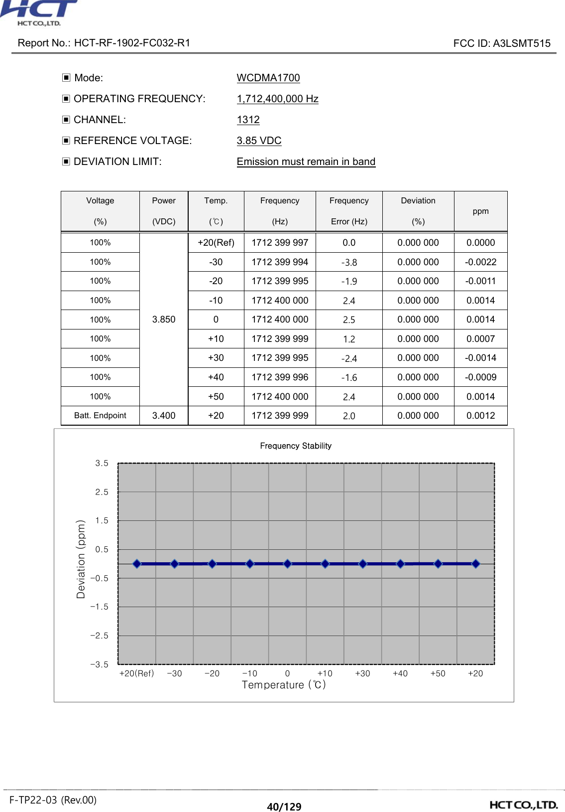
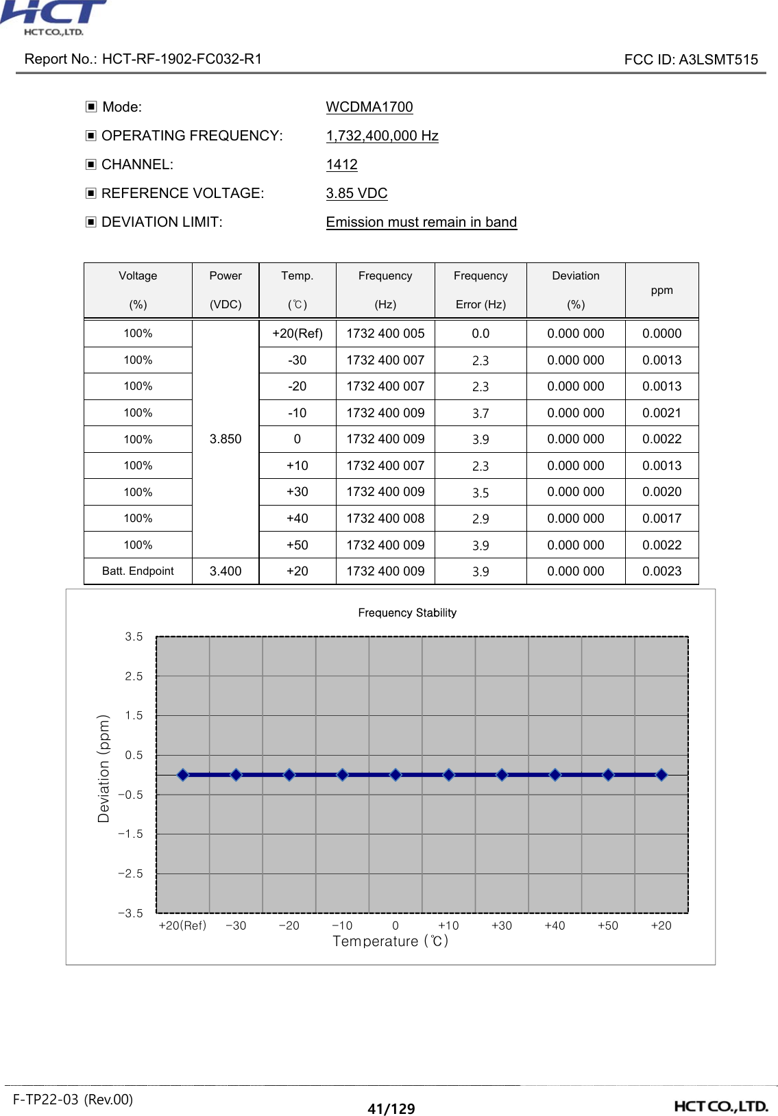
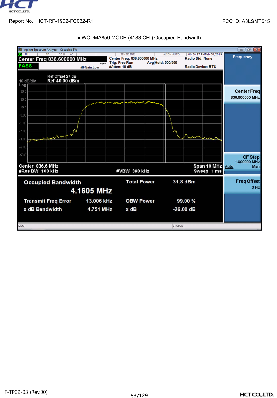
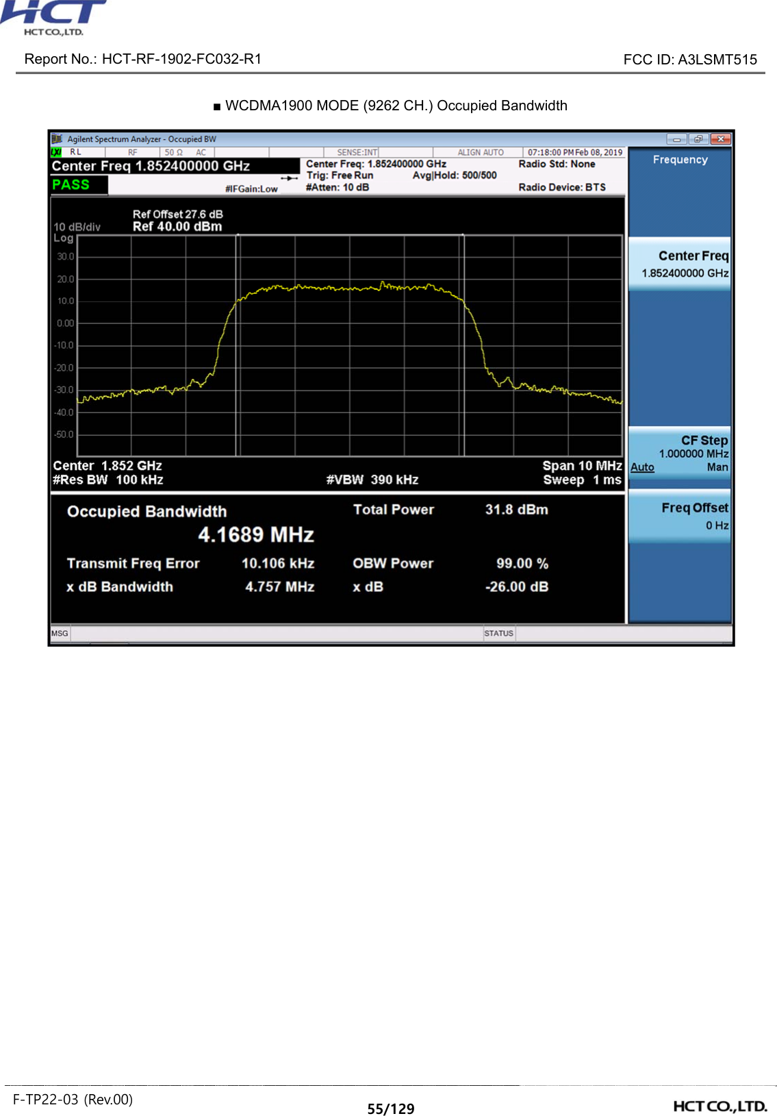
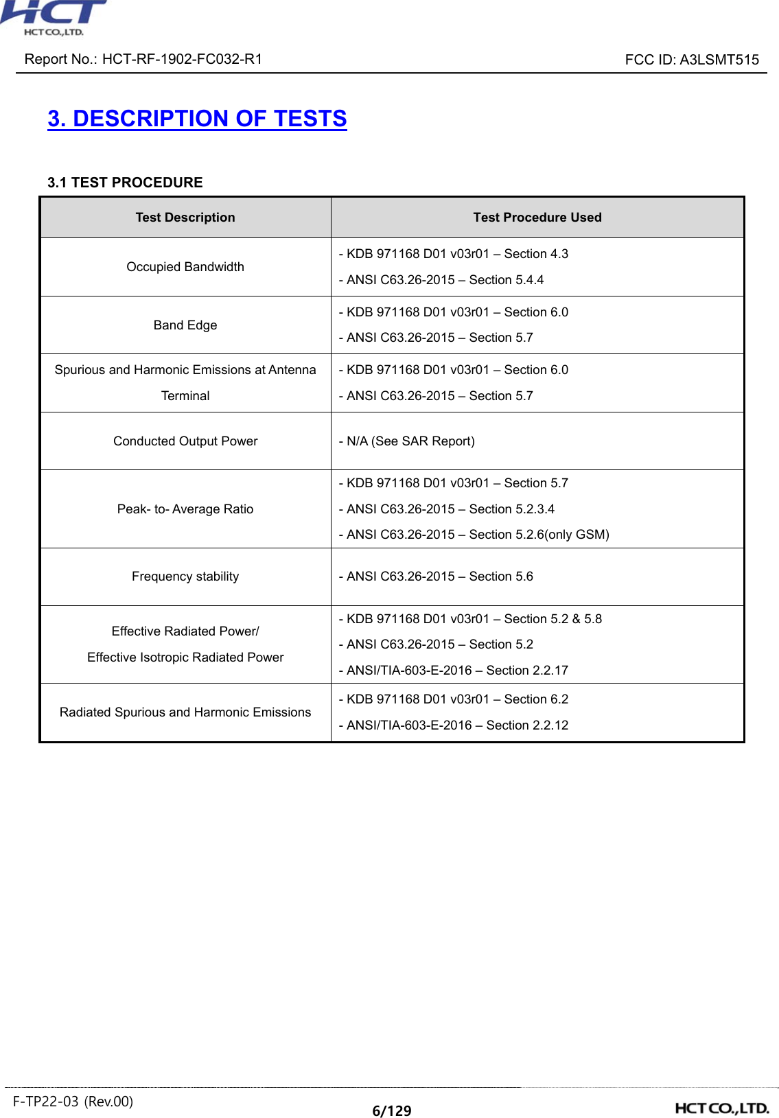
![Report No.: HCT-RF-1902-FC032-R1 FCC ID: A3LSMT515 F-TP22-03 (Rev.00) 15/129 3.9 WORST CASE(CONDUCTED TEST) - All modes of operation were investigated and the worst case configuration results are reported. [ Worst case ] Test Description Modulation Test Channel Occupied Bandwidth 2G : Voice & EDGE(1 TX Slot) 3G : QPSK Low, Mid, High 2G : EDGE(1 TX Slot) Low, Mid, High Band Edge 2G : Voice & EDGE(1 TX Slot) 3G : QPSK Low, High Spurious and Harmonic Emissions at Antenna Terminal 2G : Voice 3G : QPSK Low, Mid, High [ Test Channel ] UplinkChannel 2G (GSM850) 2G (GSM1900) 3G (WCDMA B2) 3G (WCDMA B4) 3G (WCDMA B5) Low 128 512 9262 1312 4132 Mid 190 661 9400 1412 4183 High 251 810 9538 1513 4233 Note: - SM-T515 & additional models were tested and the worst case results are reported. (Worst case : SM-T515)](https://usermanual.wiki/Samsung-Electronics-Co/SMT515.SAMSUNG-SM-T515-RF-Test-Report-2G-3G-rev01-Part1/User-Guide-4192744-Page-15.png)
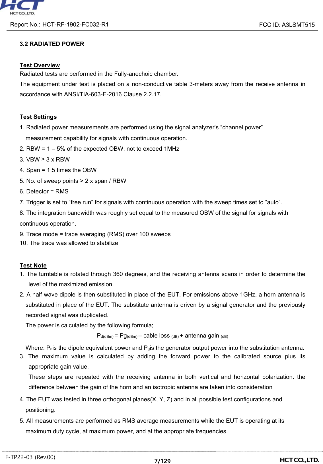
![Report No.: HCT-RF-1902-FC032-R1 FCC ID: A3LSMT515 F-TP22-03 (Rev.00) 16/129 3.10 WORST CASE(RADIATED TEST) - The EUT was tested in three orthogonal planes(X, Y, Z) and in all possible test configurations and positioning. - All modes of operation were investigated and the worst case configuration results are reported. - The worst case is reported with the EUT positioning, modulations, and paging service configurations shown in the test data. - Please refer to the table below. [ Worst case_3G ] Test Description Modulation Paging Service Axis Test Channel Effective Radiated Power, Effective Isotropic Radiated Power QPSK (WCDMA) 12.2 kbps RMC WCDMA B2 : Z WCDMA B4 : Z WCDMA B5 : X Low, Mid, High Radiated Spurious and Harmonic Emissions QPSK (WCDMA) 12.2 kbps RMC WCDMA B2 : Y WCDMA B4 : Z WCDMA B5 : X Low, Mid, High [ Worst case_2G ] Test Description Mod Axis Test Channel Effective Radiated Power, Effective Isotropic Radiated Power Voice GSM850 : X GSM1900 : Z Low, Mid, High EDGE(1 TX Slot) GSM850 : X GSM1900 : Z GSM 850 : High GSM1900 : Mid Radiated Spurious and Harmonic Emissions Voice GSM850 : Z GSM1900 : Z Low, Mid, High [ Test Channel ] UplinkChannel 2G (GSM850) 2G (GSM1900) 3G (WCDMA B2) 3G (WCDMA B4) 3G (WCDMA B5) Low 128 512 9262 1312 4132 Mid 190 661 9400 1412 4183 High 251 810 9538 1513 4233 Note: - SM-T515 & additional models were tested and the worst case results are reported. (Worst case : SM-T515)](https://usermanual.wiki/Samsung-Electronics-Co/SMT515.SAMSUNG-SM-T515-RF-Test-Report-2G-3G-rev01-Part1/User-Guide-4192744-Page-16.png)
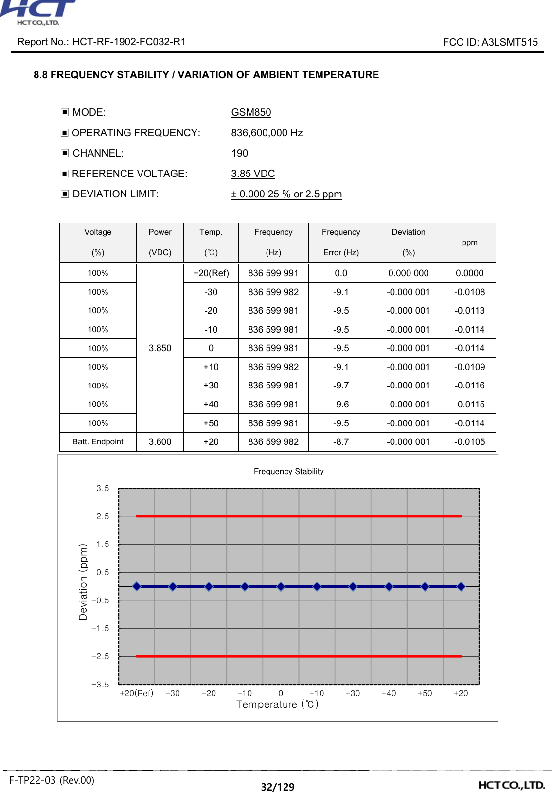
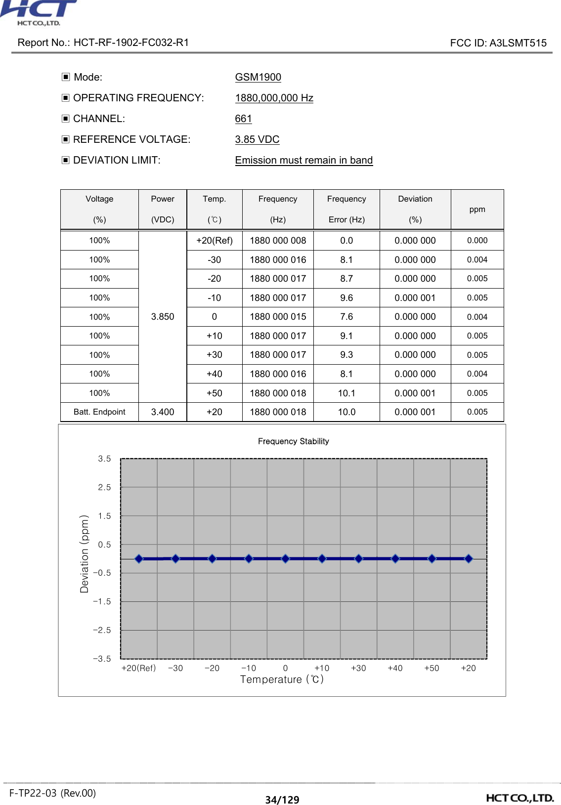
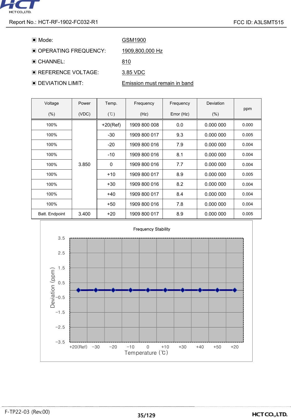
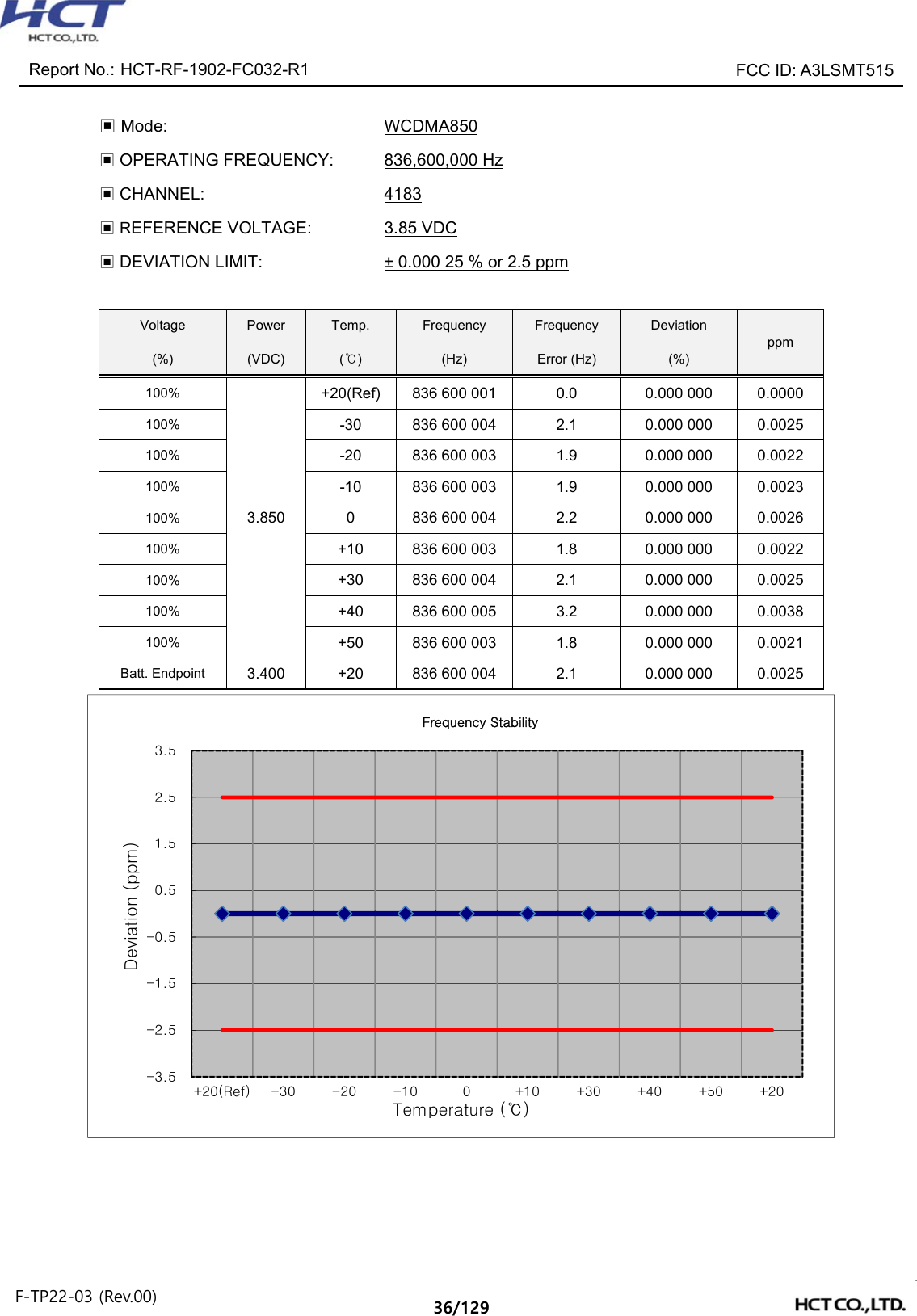
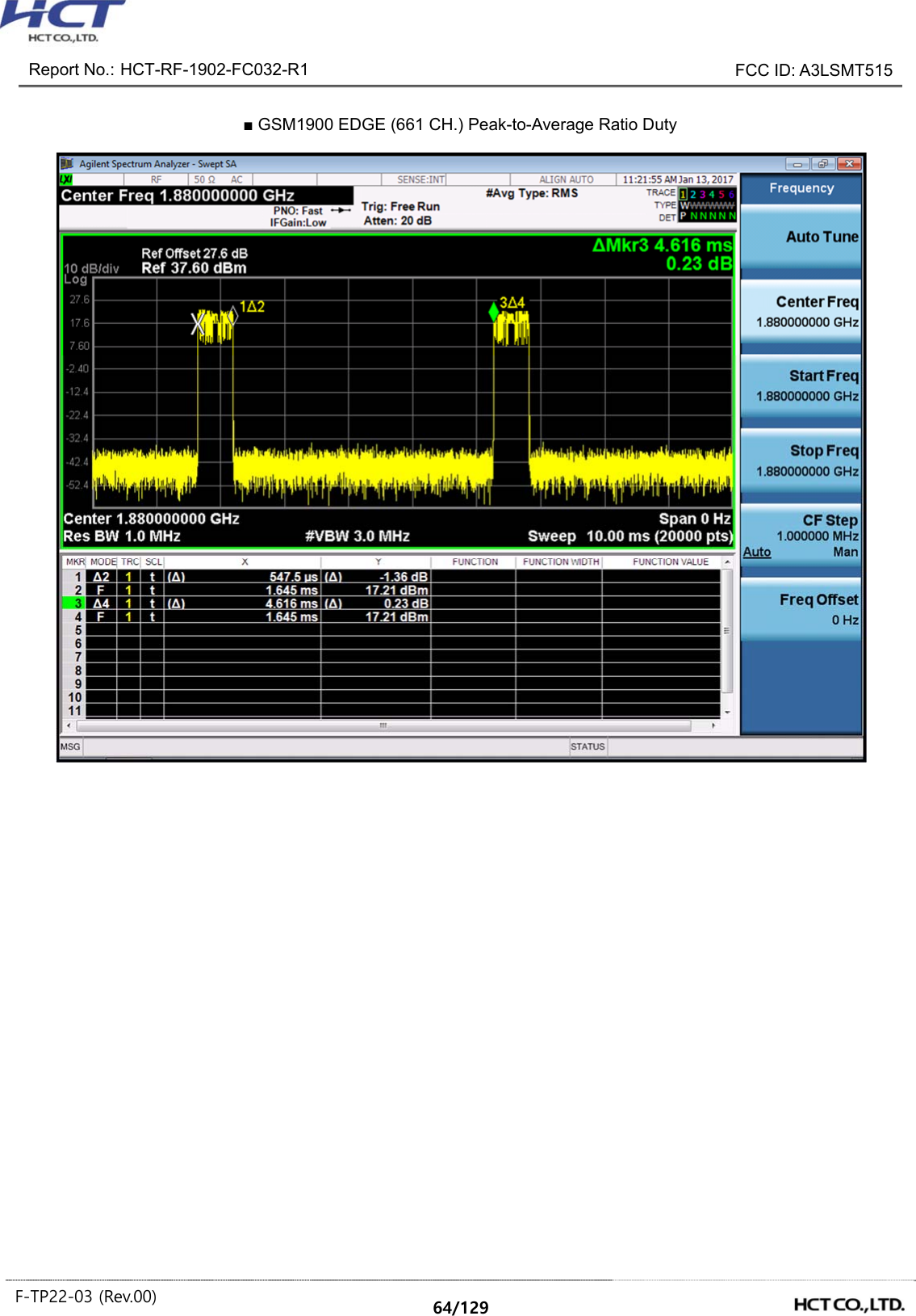
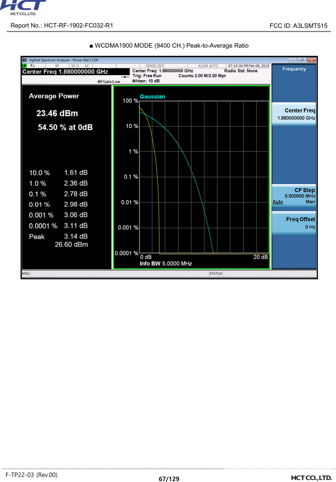
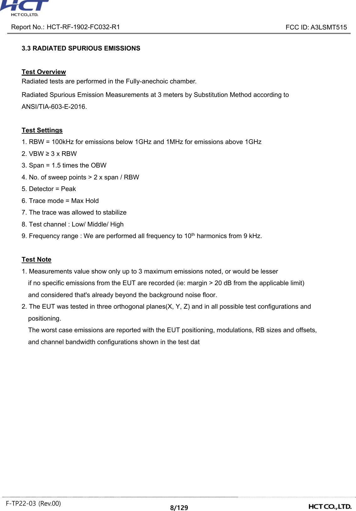
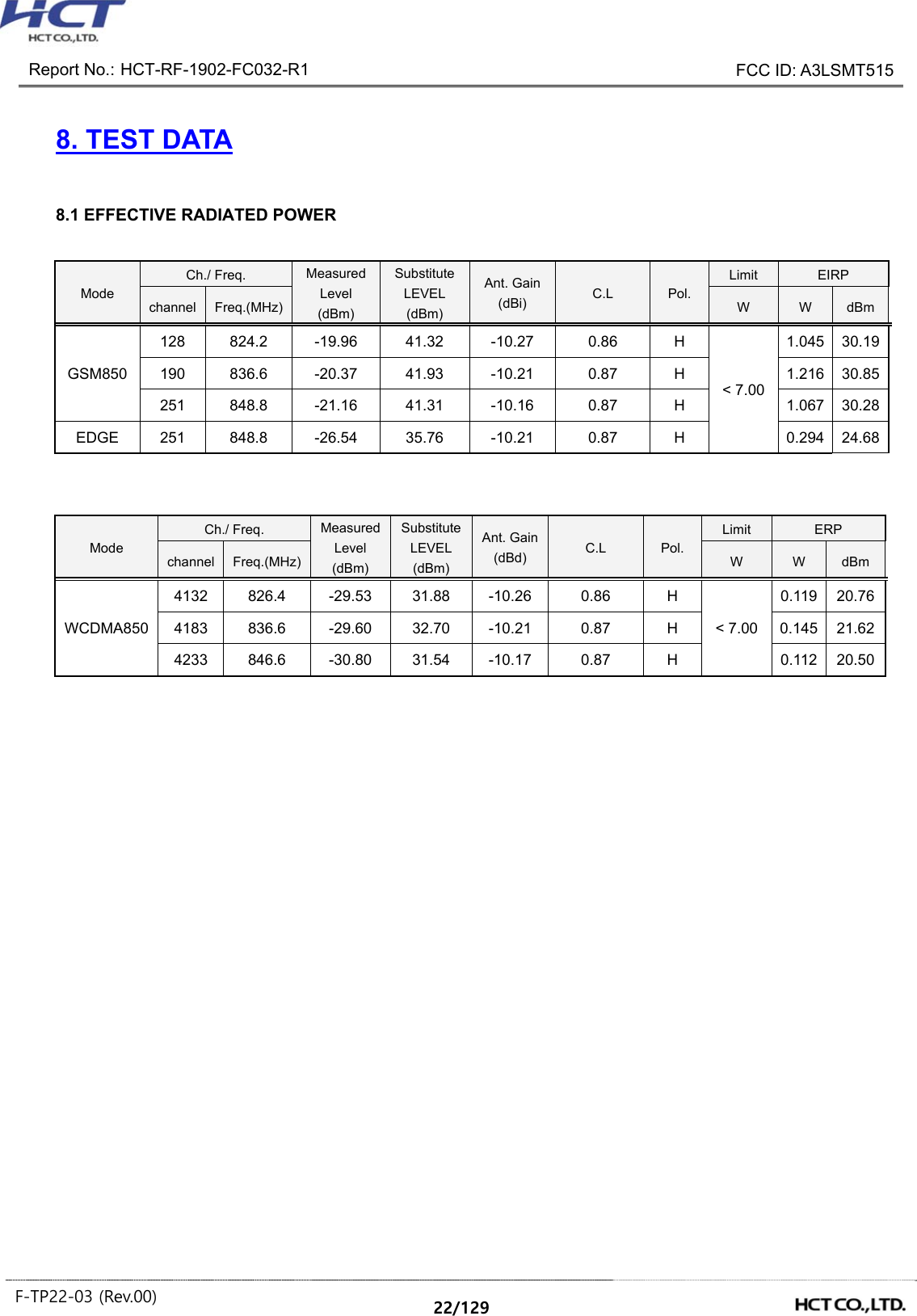
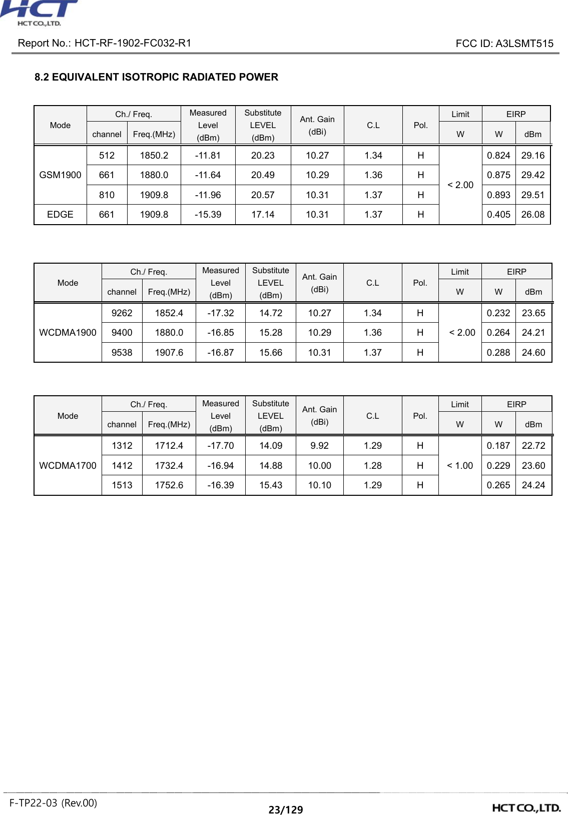
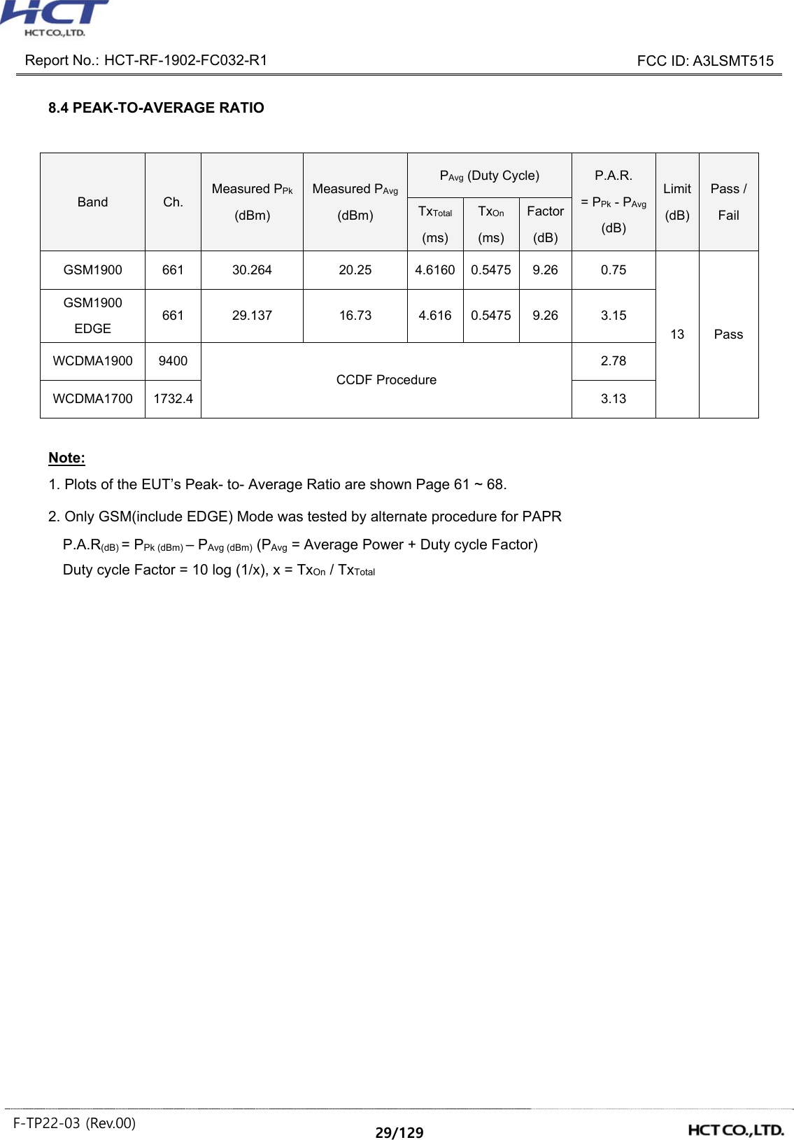
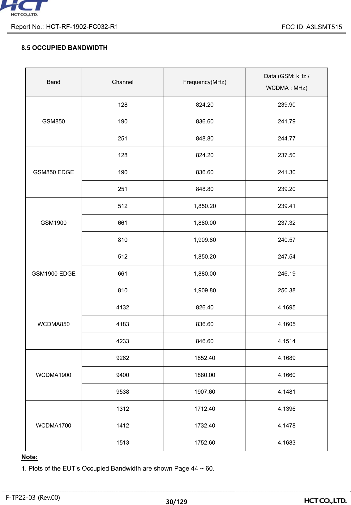
![Report No.: HCT-RF-1902-FC032-R1 FCC ID: A3LSMT515 F-TP22-03 (Rev.00) 19/129 6. SUMMARY OF TEST RESULTS 6.1 Test Condition : Conducted Test Test Description FCC Part Section(s) Test Limit Test Result Occupied Bandwidth §2.1049 N/A PASS Band Edge / Spurious and Harmonic Emissions at Antenna Terminal. §2.1051, §22.917(a), §24.238(a), §27.53(h) < 43 + 10log10 (P[Watts]) at Band Edge and for all out-of-band emissions PASS Conducted Output Power §2.1046 N/A See Note1 Peak- to- Average Ratio §24.232(d), §27.50(d)(5) < 13 dB PASS Frequency stability / variation of ambient temperature §2.1055, § 22.355 < 2.5 ppm PASS §24.235, §27.54 Emission must remain in band PASS Note: 1. See SAR Report 6.2 Test Condition : Radiated Test Test Description FCC Part Section(s) Test Limit Test Result Effective Radiated Power §22.913(a)(5) < 7 Watts max. ERP PASS Equivalent Isotropic Radiated Power §24.232(c), §27.50(d)(4) < 2 Watts max. EIRP < 1 Watts max. EIRP PASS Radiated Spurious and Harmonic Emissions §2.1053, §22.917(a), §24.238(a), §27.53(h) < 43 + 10log10 (P[Watts]) for all out-of band emissions PASS](https://usermanual.wiki/Samsung-Electronics-Co/SMT515.SAMSUNG-SM-T515-RF-Test-Report-2G-3G-rev01-Part1/User-Guide-4192744-Page-19.png)

![Report No.: HCT-RF-1902-FC032-R1 FCC ID: A3LSMT515 F-TP22-03 (Rev.00) 24/129 8.3 RADIATED SPURIOUS EMISSIONS ▣ MEASURED OUTPUT POWER: 30.85 dBm = 1.216 W ▣ MODULATION SIGNAL: GSM850 ▣ DISTANCE: 3 meters ▣ LIMIT: 43 + 10 log10 (W) = 43.85 dBc Ch. Freq.(MHz) Measured Level [dBm] Ant. Gain (dBd) Substitute Level [dBm] C.L Pol. Result (dBm) dBc 128 (824.2) 1,648.40 -32.81 7.46 -41.70 1.27 H -37.66 68.51 2,472.60 -42.10 8.64 -48.04 1.58 V -43.13 73.99 3,296.80 -56.39 10.25 -62.38 1.86 H -56.14 87.00 190 (836.6) 1,673.20 -33.92 7.53 -42.91 1.28 V -38.81 69.66 2,509.80 -45.63 8.83 -51.95 1.62 H -46.89 77.74 3,346.40 -55.79 10.51 -62.11 1.91 H -55.66 86.51 251 (848.8) 1,697.60 -36.25 7.74 -45.25 1.29 V -40.95 71.80 2,546.40 -46.46 8.86 -52.49 1.62 H -47.40 78.25 3,395.20 -56.10 10.57 -62.24 1.95 V -55.77 86.62](https://usermanual.wiki/Samsung-Electronics-Co/SMT515.SAMSUNG-SM-T515-RF-Test-Report-2G-3G-rev01-Part1/User-Guide-4192744-Page-24.png)
![Report No.: HCT-RF-1902-FC032-R1 FCC ID: A3LSMT515 F-TP22-03 (Rev.00) 25/129 ▣ MEASURED OUTPUT POWER: 29.51 dBm = 0.893 W ▣ MODULATION SIGNAL: GSM1900 ▣ DISTANCE: 3 meters ▣ LIMIT: 43 + 10 log10 (W) = 42.51 dBc Ch. Freq.(MHz) Measured Level [dBm] Ant. Gain (dBi) Substitute Level [dBm] C.L Pol. Result (dBm) dBc 512 (1850.2) 3,700.40 -57.31 12.51 -64.11 1.98 V -53.58 83.09 5,550.60 -56.91 13.62 -58.19 2.72 V -47.29 76.80 7,400.80 -57.92 11.50 -52.91 2.92 H -44.33 73.84 661 (1880.0) 3,760.00 -57.02 12.40 -63.46 2.00 V -53.06 82.57 5,640.00 -57.28 13.78 -58.11 2.70 V -47.03 76.54 7,520.00 -57.50 11.57 -52.29 2.93 H -43.65 73.16 810 (1909.8) 3,819.60 -56.31 12.52 -62.55 2.05 V -52.08 81.58 5,729.40 -57.25 13.69 -57.20 2.72 V -46.23 75.74 7,639.20 -57.47 11.99 -52.67 2.93 V -43.61 73.12](https://usermanual.wiki/Samsung-Electronics-Co/SMT515.SAMSUNG-SM-T515-RF-Test-Report-2G-3G-rev01-Part1/User-Guide-4192744-Page-25.png)
![Report No.: HCT-RF-1902-FC032-R1 FCC ID: A3LSMT515 F-TP22-03 (Rev.00) 26/129 ▣ MEASURED OUTPUT POWER: 21.62 dBm = 0.145 W ▣ MODULATION SIGNAL: WCDMA850 ▣ DISTANCE: 3 meters ▣ LIMIT: 43 + 10 log10 (W) = 34.62 dBc Ch. Freq.(MHz) Measured Level [dBm] Ant. Gain (dBd) Substitute Level [dBm] C.L Pol. Result (dBm) dBc 4,132 (826.4) 1,652.80 -50.12 7.46 -59.01 1.27 H -54.97 76.59 2,479.20 -49.54 8.71 -55.91 1.60 H -50.95 72.57 3,305.60 -57.76 10.32 -63.79 1.87 H -57.49 79.11 4,183 (836.6) 1,673.20 -52.30 7.53 -61.29 1.28 H -57.19 78.81 2,509.80 -45.45 8.83 -51.77 1.62 H -46.71 68.33 3,346.40 -56.86 10.51 -63.18 1.91 V -56.73 78.35 4,233 (846.6) 1,693.20 -53.32 7.67 -62.35 1.28 H -58.11 79.74 2,539.80 -45.13 8.85 -50.91 1.61 H -45.82 67.44 3,386.40 -56.59 10.56 -62.87 1.93 V -56.39 78.01](https://usermanual.wiki/Samsung-Electronics-Co/SMT515.SAMSUNG-SM-T515-RF-Test-Report-2G-3G-rev01-Part1/User-Guide-4192744-Page-26.png)
![Report No.: HCT-RF-1902-FC032-R1 FCC ID: A3LSMT515 F-TP22-03 (Rev.00) 27/129 ▣ MEASURED OUTPUT POWER: 24.60 dBm = 0.288 W ▣ MODULATION SIGNAL: WCDMA1900 ▣ DISTANCE: 3 meters ▣ LIMIT: 43 + 10 log10 (W) = 37.60dBc Ch. Freq.(MHz) Measured Level [dBm] Ant. Gain (dBi) Substitute Level [dBm] C.L Pol. Result (dBm) dBc 9262 (1852.4) 3,704.80 -56.87 12.50 -63.50 1.99 H -52.99 77.59 5,557.20 -55.27 13.64 -56.51 2.71 H -45.58 70.18 7,409.60 -57.59 11.50 -52.30 2.93 V -43.73 68.33 9400 (1880.0) 3,760.00 -58.00 12.40 -64.44 2.00 V -54.04 78.64 5,640.00 -57.78 13.78 -58.61 2.70 H -47.53 72.13 7,520.00 -58.57 11.57 -53.36 2.93 H -44.72 69.32 9538 (1907.6) 3,815.20 -57.20 12.52 -63.57 2.06 H -53.10 77.70 5,722.80 -57.62 13.70 -57.31 2.72 V -46.33 70.93 7,630.40 -57.61 11.95 -52.80 2.98 V -43.83 68.42](https://usermanual.wiki/Samsung-Electronics-Co/SMT515.SAMSUNG-SM-T515-RF-Test-Report-2G-3G-rev01-Part1/User-Guide-4192744-Page-27.png)
![Report No.: HCT-RF-1902-FC032-R1 FCC ID: A3LSMT515 F-TP22-03 (Rev.00) 28/129 ▣ MEASURED OUTPUT POWER: 24.24 dBm = 0.265 W ▣ MODULATION SIGNAL: WCDMA1700 ▣ DISTANCE: 3 meters ▣ LIMIT: 43 + 10 log10 (W) = 37.24 dBc Ch. Freq.(MHz) Measured Level [dBm] Ant. Gain (dBi) Substitute Level [dBm] C.L Pol. Result (dBm) dBc 1312 (1712.4) 3,424.80 -57.50 12.69 -65.50 1.90 V -54.71 78.95 5,137.20 -56.48 12.75 -58.19 2.52 V -47.96 72.20 6,849.60 -42.82 12.52 -40.06 2.81 H -30.35 54.59 1412 (1732.4) 3,464.80 -57.66 12.60 -65.25 1.97 V -54.62 78.86 5,197.20 -56.92 13.17 -58.83 2.54 H -48.20 72.44 6,929.60 -45.24 12.46 -41.91 2.83 H -32.28 56.52 1513 (1752.6) 3,505.20 -57.17 12.44 -64.43 1.92 V -53.91 78.15 5,257.80 -57.62 13.48 -60.43 2.59 V -49.54 73.78 7,010.40 -54.58 12.24 -51.60 2.84 H -42.20 66.44](https://usermanual.wiki/Samsung-Electronics-Co/SMT515.SAMSUNG-SM-T515-RF-Test-Report-2G-3G-rev01-Part1/User-Guide-4192744-Page-28.png)
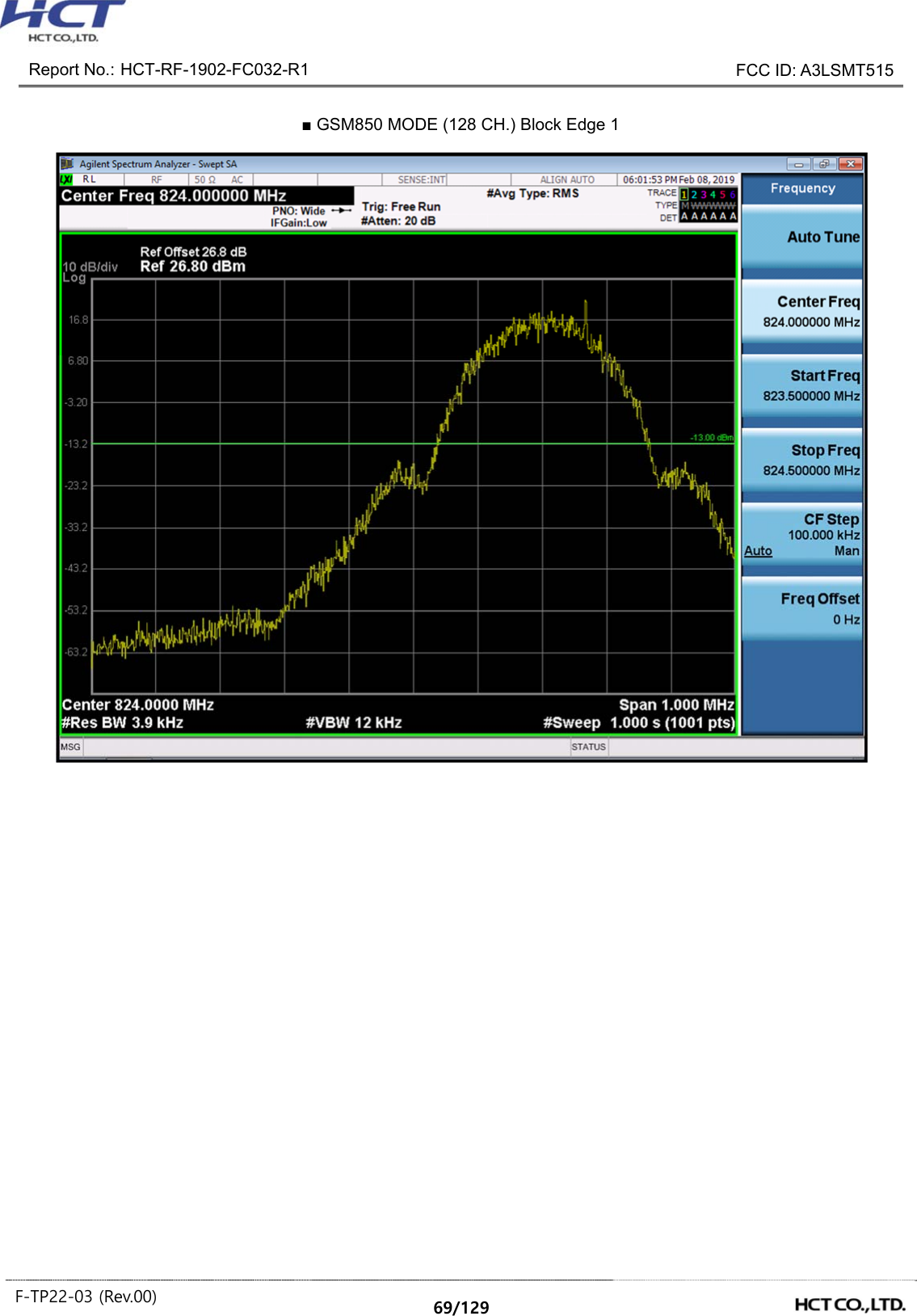
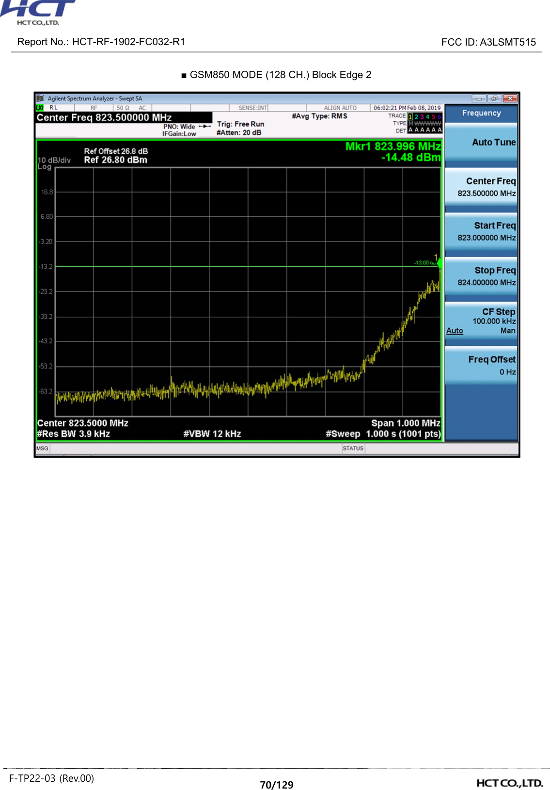
![Report No.: HCT-RF-1902-FC032-R1 FCC ID: A3LSMT515 F-TP22-03 (Rev.00) 31/129 8.6 CONDUCTED SPURIOUS EMISSIONS Note: 1. Plots of the EUT’s Conducted Spurious Emissions are shown Page 105 ~ 128. 2. Result (dBm) = Measurement Maximum Data (dBm) + Factor (dB) 3. Factor(dB) = Cable Loss + Attenuator + Power Splitter Frequency Range (GHz) Factor [dB] 0.03 – 1 25.270 1 – 5 27.976 5 – 10 28.591 10 – 15 29.116 15 – 20 29.489 Above 20 30.131 8.7 BAND EDGE - Plots of the EUT’s Band Edge are shown Page 69 ~ 104. Band Channel Frequency of Maximum Harmonic (GHz) Factor (dB) Measurement Maximum Data (dBm) Result (dBm) GSM850 128 2.4731 27.976 -57.10 -29.121 -13.00 190 3.7099 27.976 -57.45 -29.476 251 3.6865 27.976 -56.96 -28.981 GSM1900 512 18.87897 29.489 -53.160 -23.671 661 19.51774 29.489 -52.480 -22.991 810 17.00918 29.489 -52.890 -23.401 WCDMA850 4132 3.6950 27.976 -77.191 -49.215 4183 3.6965 27.976 -77.257 -49.281 4233 3.7039 27.976 -77.217 -49.241 WCDMA1900 9262 18.9262 29.489 -72.811 -43.322 9400 18.9177 29.489 -72.657 -43.168 9538 18.8965 29.489 -72.809 -43.320 WCDMA1700 1712 18.91372 29.489 -72.825 -43.336 1732 18.88797 29.489 -73.064 -43.575 1753 18.93197 29.489 -73.147 -43.658](https://usermanual.wiki/Samsung-Electronics-Co/SMT515.SAMSUNG-SM-T515-RF-Test-Report-2G-3G-rev01-Part1/User-Guide-4192744-Page-31.png)