Samsung Electronics Co SPH700 Projector User Manual
Samsung Electronics Co Ltd Projector Users Manual
UserManual.wiki
>
Samsung Electronics Co
>
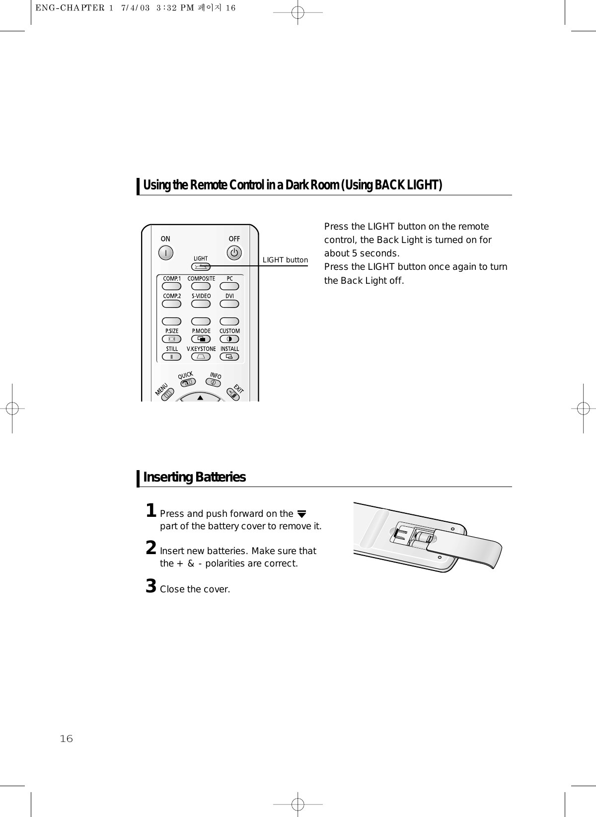
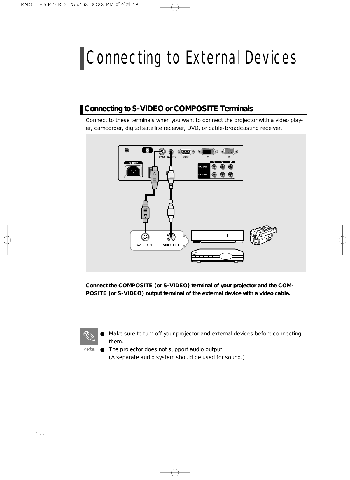
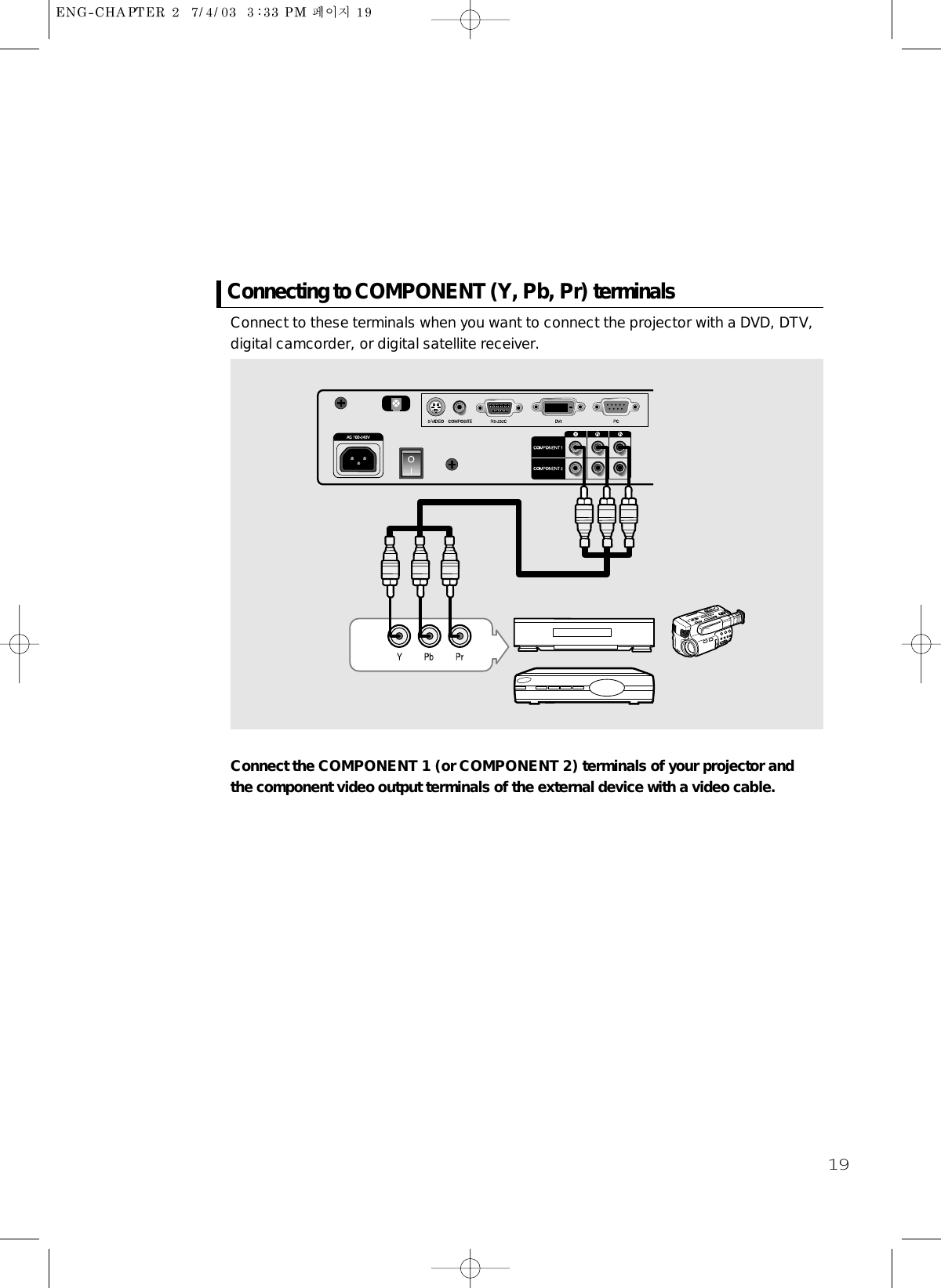
SPH700 User Manual
Users Manual
Navigation menu
Upload a User Manual
Namespaces
Wiki Guide
HTML
PDF
Info
Views
User Manual
Discussion / Help
Navigation