Samsung Electronics Co SPH700 Projector User Manual
Samsung Electronics Co Ltd Projector Users Manual
Users Manual

Owner's
Instructions
SAMSUNG PROJECTOR
.....................................................................................................................................
.............
SHP-700
AA68-00000A-00
Warning! Important
Safety Instructions
CAUTION: TO REDUCE THE RISK OF ELECTRIC SHOCK, DO NOT
REMOVE COVER (OR BACK). NO USER SERVICEABLE PARTS INSIDE.
REFER SERVICING TO QUALIFIED SERVICE PERSONNEL.
This symbol indicates high voltage is present inside. It is
dangerous to make any kind of contact with any inside part of
this product.
This symbol alerts you that important literature concerning
operation and maintenance has been included with this product.
Note to CATV system installer: This reminder is provided to call CATV system
installer’s attention to Article 820-40 of the National Electrical Code (Section 54 of
Canadian Electrical Code, Part I), that provides guidelines for proper grounding
and, in particular, specifies that the cable ground shall be connected to the
grounding system of the building as close to the point of cable entry as practical.
Caution: FCC/CSA regulations state that any unauthorized changes or modifica-
tions to this equipment may void the user’s authority to operate it.
Caution: To prevent electric shock, match the wide blade of plug to the wide slot,
and fully insert the plug.
Attention: pour eviter les chocs electriques, introduire la lame le plus large de la
fiche dans la borne correspondante de la prise et pousser jusqu’au fond.
Important: One Federal Court has held that unauthorized recording of
copyrighted TV programs is an infringement of U.S. copyright laws.
Certain Canadian programs may also be copyrighted and any unauthorized
recording in whole or in part may be in violation of these rights.
To prevent damage which may result in fire or electric shock
hazard, do not expose this appliance to rain or moisture.
CAUTION
RISK OF ELECTRIC SHOCK
DO NOT OPEN
2

Thank You for Choosing Samsung
Thank you for choosing Samsung! Your new Samsung TV represents the latest in television
technology. We designed it with easy-to-use on-screen menus and closed captioning capabili-
ties, making it one of the best products in its class. We are proud to offer you a product that
will provide convenient, dependable service and enjoyment for years to come.
Important Safety Information
Always be careful when using your TV receiver. To reduce the risk of fire, electrical shock,
and other injuries, keep these safety precautions in mind when installing, using, and
maintaining your machine.
• Read all safety and operating instructions before operating your TV.
• Keep the safety and operating instructions for future reference.
• Heed all warnings on the TV receiver and in the operating instructions.
• Follow all operating and use instructions.
• Unplug the TV receiver from the wall outlet before cleaning. Use a damp cloth; do not use
liquid or aerosol cleaners.
• Never add any attachments and/or equipment without approval of the manufacturer. Such
additions can increase the risk of fire, electric shock, or other personal injury.
• Do not use the TV receiver where contact with or immersion in water is a possibility, such as
near bath tubs, sinks, washing machines, swimming pools, etc.
• Do not place the TV on an unstable cart, stand, tripod, bracket, or
table where it can fall. A falling TV can cause serious injury to a
child or adult, and serious damage to the appliance. Use only with
a cart, stand, tripod, bracket, or table recommended by the manu-
facturer or sold with the TV. Follow the manufacturer’s instruc-
tions when mounting the unit, and use a mounting accessory rec-
ommended by the manufacturer. Move the TV and cart with care.
Quick stops, excessive force, and uneven surfaces can make the
unit and cart unsteady and likely to overturn.
• Provide ventilation for the TV receiver. The unit is designed with slots in the cabinet for ven-
tilation to protect it from overheating. Do not block these openings with any object, and do
not place the TV receiver on a bed, sofa, rug, or other similar surface. Do not place it near a
radiator or heat register. If you place the TV receiver on a rack or bookcase, ensure that there
is adequate ventilation and that you’ve followed the manufacturer’s instructions for mount-
ing.
• Operate your TV receiver only from the type of power source indicated on the marking label.
If you are not sure of the type of power supplied to your home, consult your appliance dealer
or local power company.
• Use only a grounded or polarized outlet. For your safety, this TV is equipped with a polarized
alternating current line plug having one blade wider than the other. This plug will fit into the
power outlet only one way. If you are unable to insert the plug fully into the outlet, try
reversing the plug. If the plug still does not fit, contact your electrician to replace your outlet.
3
4
• Protect the power cord. Power supply cords should be routed so that they won’t be walked
on or pinched by objects placed on or against them. Pay particular attention to cords at
plugs, convenience receptacles, and the point where they exit from the unit.
• Unplug the TV from the wall outlet and disconnect the antenna or cable system during a
lightning storm or when left unattended and unused for long periods of time. This will pre-
vent damage to the unit due to lightning and power-line surges.
• Avoid overhead power lines. An outside antenna system should not be placed in the vicinity
of overhead power lines or other electric light or power circuits or where it can fall into such
power lines or circuits. When installing an outside antenna system, be extremely careful to
keep from touching the power lines or circuits. Contact with such lines can be fatal.
• Do not overload the wall outlet or extension cords. Overloading can result in fire or electric
shock.
• Do not insert anything through the openings in the
unit, where they can touch dangerous voltage points
or damage parts. Never spill liquid of any kind on the
TV.
• Ground outdoor antennas. If an outside antenna or
cable system is connected to the TV, be sure the
antenna or cable system is grounded so as to provide
some protection against voltage surges and built-up
static charges. Section 810 of the National Electrical
Code, ANSI/NFPA No.70-1984, provides information
about proper grounding of the mast and supporting structure, grounding of the lead-in wire
to an antenna discharge unit, size of grounding conductors, location of antenna discharge
unit, connection to grounding electrodes, and requirements for the grounding electrode.
• Do not attempt to service the TV yourself. Refer all servicing to qualified service personnel.
Unplug the unit from the wall outlet and refer servicing to qualified service personnel under
the following conditions:
- when the power-supply cord or plug is damaged
- if liquid has been spilled on the unit or if objects have fallen into the unit
- if the TV has been exposed to rain or water
- if the TV does not operate normally by following the operating instructions
- if the TV has been dropped or the cabinet has been damaged
- when the TV exhibits a distinct change in performance
• If you make adjustments yourself, adjust only those controls that are covered by the operat-
ing instructions. Adjusting other controls may result in damage and will often require exten-
sive work by a qualified technician to restore the TV to normal.
• When replacement parts are required, be sure the service technician uses replacement parts
specified by the manufacturer or those that have the same characteristics as the original part.
Unauthorized substitutions may result in additional damage to the unit.
• Upon completion of any service or repairs to this TV, ask the service technician to
perform safety checks to determine that the TV is in a safe operating condition.
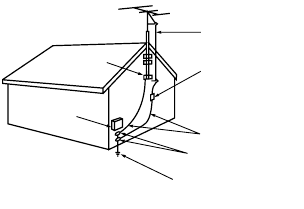
ANTENNA
LEAD IN WIRE
ANTENNA
DISCHARGE UNIT
(NEC SECTION 810-20)
GROUNDING
CONDUCTORS
(NEC SECTION 810-21)
GROUND CLAMPS
POWER SERVICE GROUNDING
ELECTRODE SYSTEM
(NEC ART 250, PART H)
GROUND CLAMP
ELECTRIC
SERVICE
EQUIPMENT
NEC — NATIONAL ELECTRICAL CODE
EXAMPLE OF
ANTENNA GROUNDING

5
FCC Information
User Instructions
The Federal Communications Commission
Radio Frequency Interference Statement
includes the following warning:
Note: This equipment has been tested and
found to comply with the limits for a Class B
digital device, pursuant to Part 15 of the FCC
Rules. These limits are designed to provide
reasonable protection against harmful inter-
ference in a residential installation. This
equipment generates, uses, and can radiate
radio frequency energy and, if not installed
and used in accordance with the instructions,
may cause harmful interference to radio com-
munications. However, there is no guarantee
that interference will not occur in a particular
installation. If this equipment does cause
harmful interference to radio or television
receptions, which can be determined by turn-
ing the equipment off and on, the user is
encouraged to try to correct the interference
by one or more of the following measures:
Reorient or relocate the receiving antenna.
Increase the separation between the equip-
ment and receiver.
Connect the equipment into an outlet on a
circuit different from that to which the receiv-
er is connected.
Consult the dealer or an experienced
radio/TV technician for help.
User Information
Changes or modifications not expressly
approved by the party responsible for compli-
ance could void the user's authority to oper-
ate the equipment. If necessary, consult your
dealer or an experienced radio/television
technician for additional suggestions. You
may find the booklet called How to Identify
and Resolve Radio/TV Interference Problems
helpful. This booklet was prepared by the
Federal Communications Commission. It is
available from the U.S. Government Printing
Office, Washington, DC 20402, Stock
Number 004-000-00345-4.
The party responsible for product compli-
ance:
SAMSUNG ELECTRONICS CO., LTD
America QA Lab of Samsung
3351 Michelson Drive,
Suite #290, Irvine, CA92612 USA
Tel) 949-975-7310
Fax) 949-922-8301
Warning
User must use shielded signal interface cables
to maintain FCC compliance for the product.
Provided with this monitor is a detachable
power supply cord with IEC320 style termi-
nations. It may be suitable for connection to
any UL Listed personal computer with similar
configuration. Before making the connection,
make sure the voltage rating of the computer
convenience outlet is the same as the monitor
and that the ampere rating of the computer
convenience outlet is equal to or exceeds the
monitor voltage rating.
For 120 Volt applications, use only UL Listed
detachable power cord with NEMA configu-
ration 5-15P type (parallel blades) plug cap.
For 240 Volt applications use only UL Listed
Detachable power supply cord with NEMA
configuration 6-15P type (tandem blades)
plug cap.
-------------------------------------------------------
IC Compliance Notice
This Class B digital apparatus meets all
requirements of the Canadian Interference-
Causing Equipment Regulations of ICES-003.
Cet appareil Numérique de classe B respecte
toutes les exigences du Règlemo
équipements produisant des interférences au
Canada.
-------------------------------------------------------
PCT Notice
-------------------------------------------------------
VCCI
This is a Class B product based on the stan-
dard of the Voluntary Control Council for
Interference by Information Technology
Equipment (VCCI). If this is used near a
radio or television receiver in a domestic
environment, it may cause radio interference.
Install and use the equipment according to
the instruction manual.

ISUAL REALISM
Product Features ....................10
List of Parts............................12
Remote Control Buttons............14
Using the Remote Control..........15
1 Before You Begin

10
10
Wide DMD (Digital Micromirror Device) Chip
■ The DMD chip provides a higher screen resolution with an aspect ratio of 16:9
which gives you the best visual experience. The optimized screen frame allows
you to watch software with a 16:9 aspect ratio recorded by DVD or DTV.
※ DLP (Digital Light Processing) and DMD (Digital Micromirror Device) are reg-
istered trademarks of Texas Instruments.
Maximum Screen Resolution: 720P
■ The high resolution panel of 921,000 pixels (1280 X 720 dots) provides not only
an HDTV 720P signal but also high quality pictures which have the same resolu-
tion as the original.
Minimizing Fan Noise
■ The new optical engine developed for this product minimizes the fan noise which
can hinder your viewing pleasure.
Using with DTV
■ Viewing DTV pictures and 16:9 wide-screen pictures is possible when connected
to a DTV decoder or similar video system.
■ DTV is a general term used to refer to the new digital television system in the
USA.
New Progressive Mode and Film Mode
■ Pictures are optimized by converting a cross signal into Progressive Mode. This
is useful for watching slow motion or still pictures. There are three modes avail-
able.
New Video Circuit
■ Provides a high quality picture with minimal dot trawl and cross color noise.
Product Features

11
11
Convenient Graphic User Interface (GUI)
■ The Main System composed of various color icons which allows you to control
pictures simply and easily.
Color Temperature Control
■ This function is used to control color temperature in order to appropriately adapt
the shape of the pictures input into the projector.
Gamma Compensation
■ The Gamma Value may be adjusted according to the input pictures in order to
optimize picture density.
Brightness Adjustment
■ This button is used to control the quantity of light projected. You can adjust the
brightness, power consumption, and fan noise by selecting General or Bright.
Component Signal Video Input
■ Component Signal Video Inputs (Y,Cb,Cr) are used. Divided component signals
are provide better color and picture quality.
Direct Computer Compatibility
■ Multi-Scan RGB inputs can receive signals from VGA (640 dots X 480 lines),
SXGA (1280 dots X 1024 lines), and Macintosh (from 13 to 21 inches) without
using auxiliary hardware.
12
12
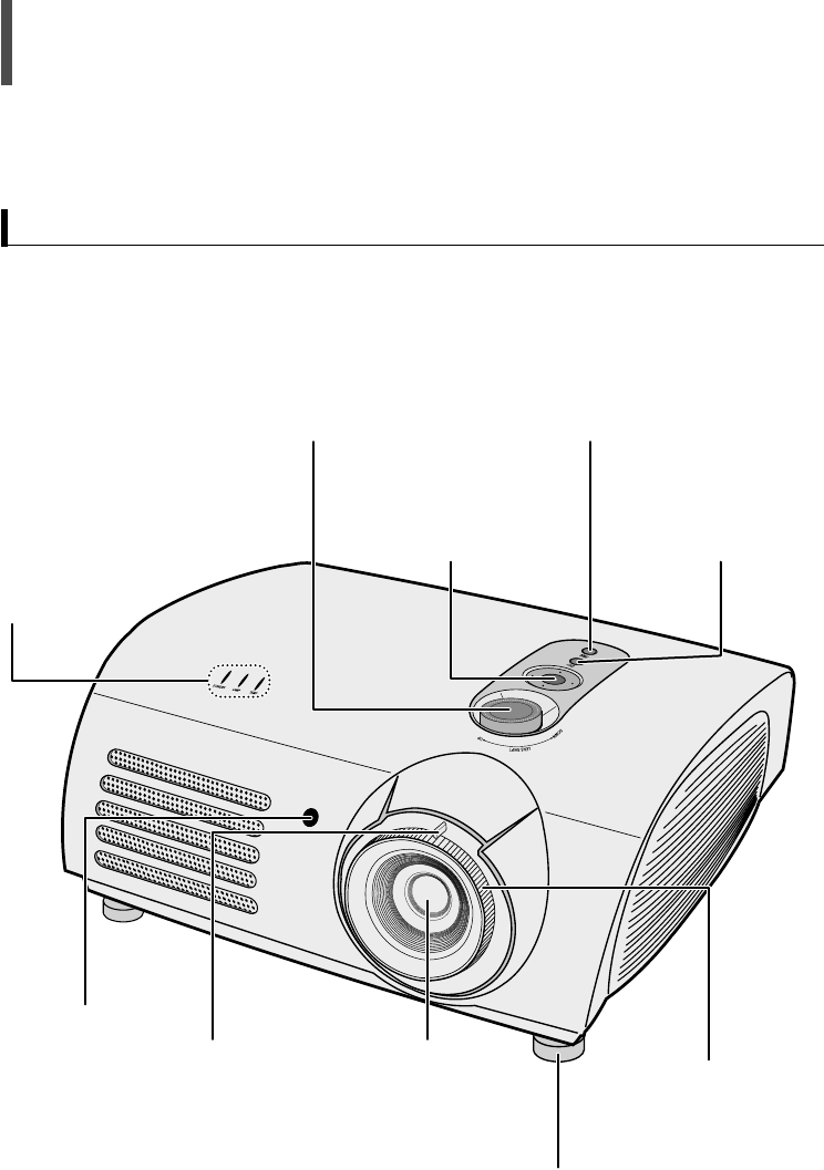
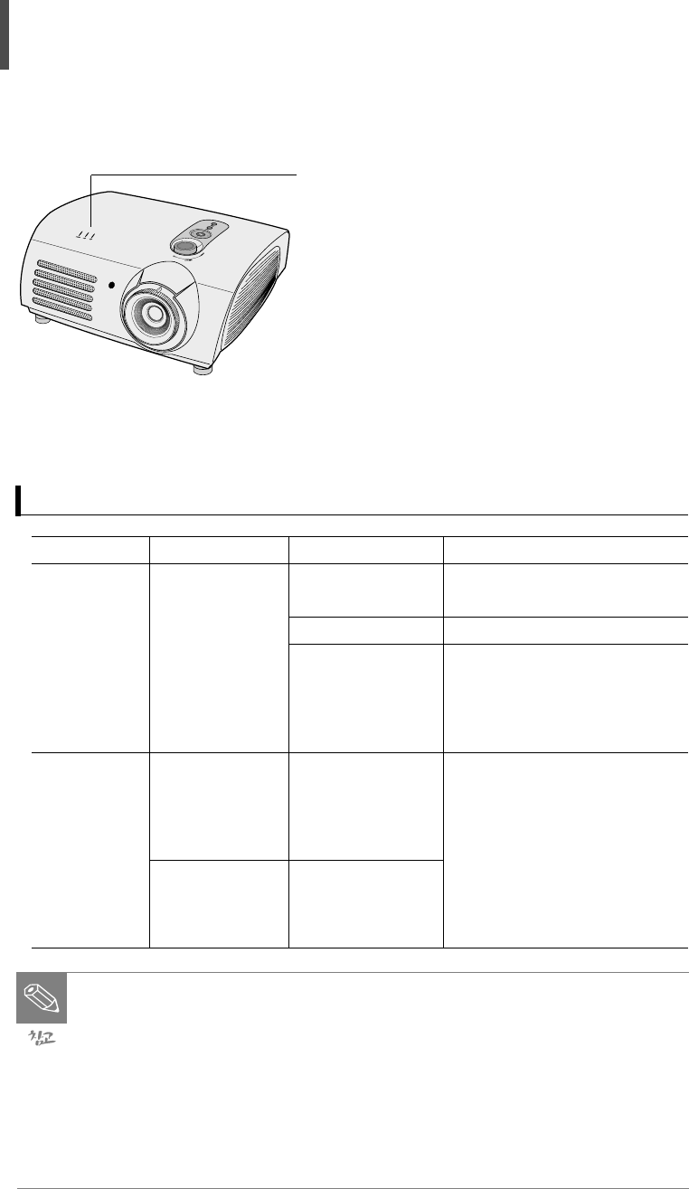
Lens Shift Dial
The image can be controlled
(within the movable range of
the lens) by turning this dial
on the top of the projector
with your fingers.
External Input
Selection Button
Selects the external
device signals.
Power Button
Turns the projector
Power ON/OFF.
Menu and Move
Button
Selects a menu or
moves to the menu bar.
Zoom Control
Zooms the image in
or out.
Focus Ring
Adjusts focus.
Height Adjustment Foot
The height of image can be
adjusted by moving it up or
down.
Lens
Remote Control
Receiver
LED Indicator
LAMP: This LED turns
on when the lamp
needs replacement.
TEMP: This LED indica-
tor turns on when the
projector generates too
much heat and has
trouble inside.
List of Parts
Front
13
13
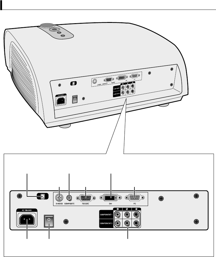
S-VIDEO Input
Terminal
COMPOSITE
Terminal
Remote Control
Receiver
RS-232C
Port
DVI Input
Terminal
PC Input
Terminal
AC Power
Input Power Input
Switch COMPONENT 1 &
2 Input Terminals
Rear
14
14
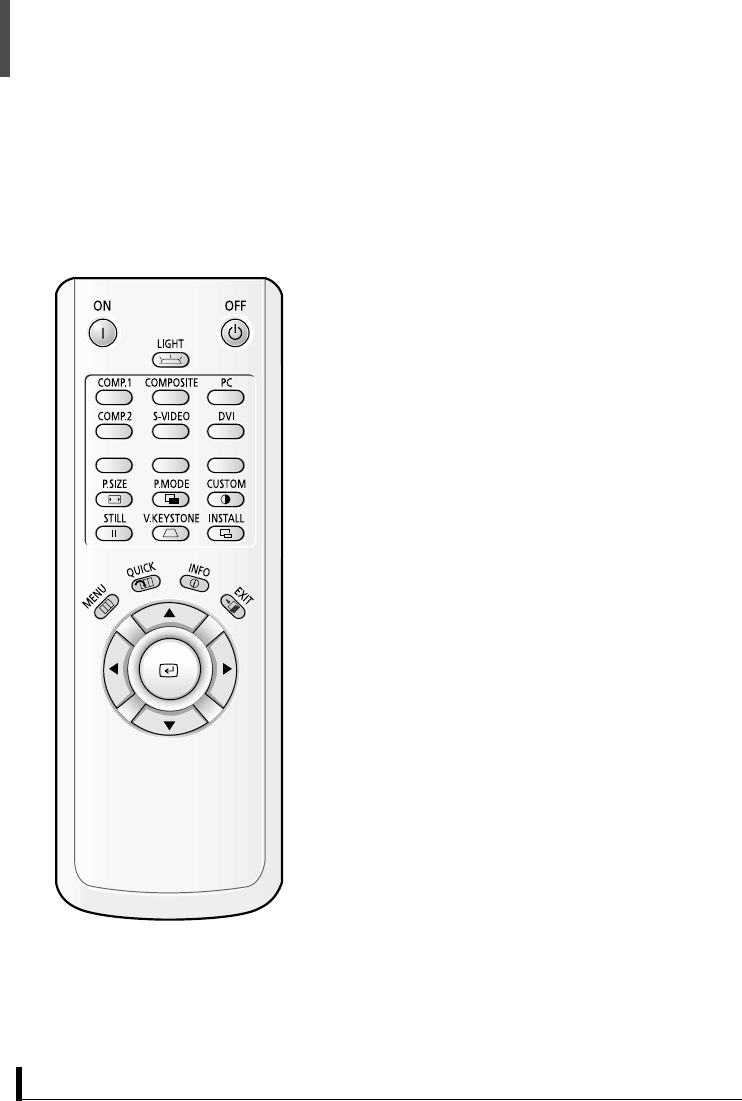
Œ
Power button
Turns the projector power ON/OFF.
´
LIGHT button
ˇ
P.SIZE button
¨
P.MODE button
ˆ
CUSTOM button
Ø
STILL button
Stops the moving image (freeze frame).
∏
V.KEYS button
”
INSTALL button
’
MENU button
˝
QUICK button
Moves to the previous menu.
Ô
INFObutton
EXIT button
Ò
ENTER button
Selects a menu.
Ú
Move button
Selects a menu or moves to the menu bar.
Please check these items:
1. Check whether the polarities of batteries are correct.
2. Check whether a battery has run out.
3. Check whether a power failure occurred.
4. Check whether the power cord is disconnected.
5. Check whether a fluorescent or neon lamp is turned on nearby.
When the Remote Control Does Not Operate
Remote Control Buttons
15
15
Remote Control,
Batteries
(Two AA size)
Power
Cord Owner's
Instructions Video Cable Lens Cover
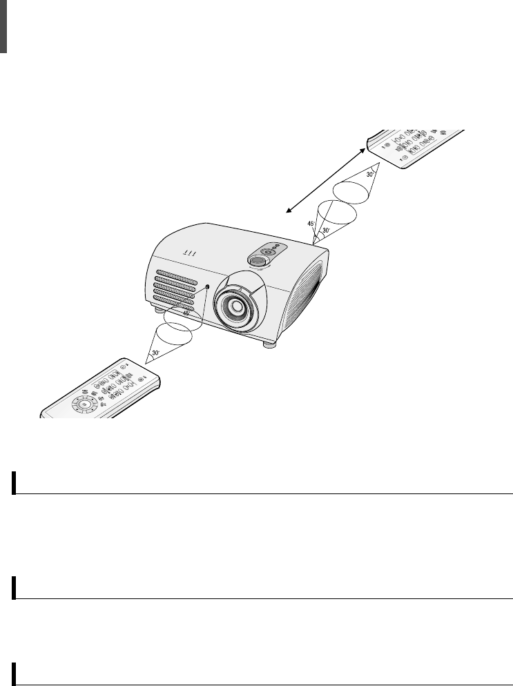
● The remote control should be used within 7~10m from the remote control
receiver on the projector.
● Acceptable angles are up to 30 degrees to the right and left.
Remote Control Receiving Angle
● Properly dispose of used batteries due to adverse environmental effects.
Properly Dispose of Used Batteries
※ Please contact a Samsung service center, household appliances store, or
electrical parts shop to purchase accessories and other devices separately.
Package Contents
Using the Remote Control
16
1Press and push forward on the
part of the battery cover to remove it.
2Insert new batteries. Make sure that
the + & - polarities are correct.
3Close the cover.
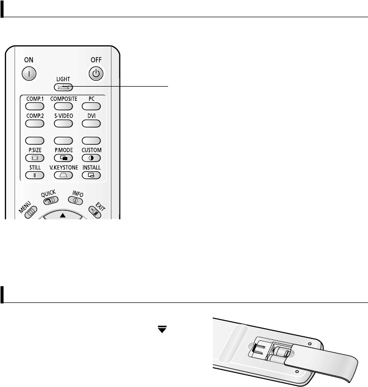
Press the LIGHT button on the remote
control, the Back Light is turned on for
about 5 seconds.
Press the LIGHT button once again to turn
the Back Light off.
Using the Remote Control in a Dark Room (Using BACK LIGHT)
Inserting Batteries
LIGHT button

ISUAL REALISM
Connecting to External Devices ..18
Installing Your Projector ............22
Powering On/Off ....................23
Adjusting the Projector Feet ......24
Using the Lens Shift Dial ..........24
Installing Your Projector Behind
the Screen ............................25
Installing Your Projector In Front of
the Screen ............................25
Using the Zoom and Adjusting
Focus....................................26
Selecting an External Device......26
Editing Input Device Names ......27
Gamma Compensation ............28
Setting Screen Modes ..............29
Customizing Screen Modes ......30
Adjusting Color Temperature ....31
Image Projection Method ..........32
Setting Up the Theater Function
..33
2 Connecting and Using
18
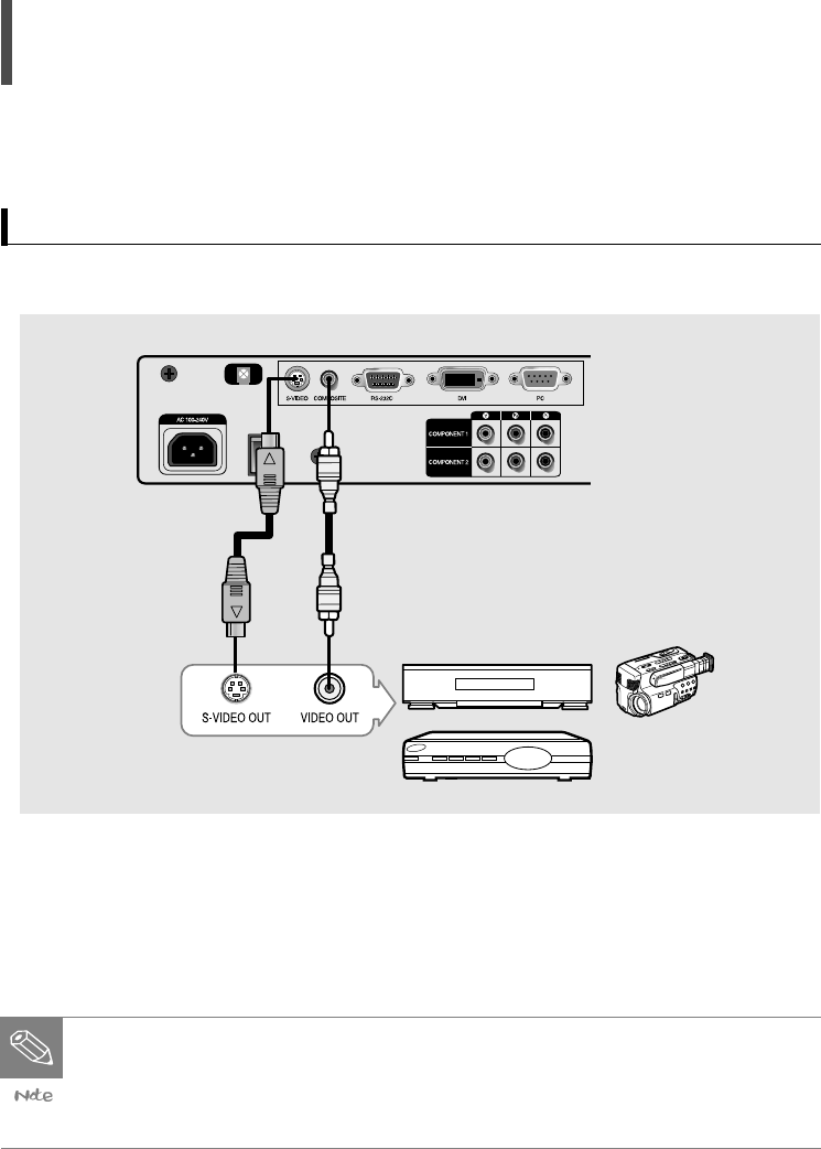
Connect to these terminals when you want to connect the projector with a video play-
er, camcorder, digital satellite receiver, DVD, or cable-broadcasting receiver.
Connect the COMPOSITE (or S-VIDEO) terminal of your projector and the COM-
POSITE (or S-VIDEO) output terminal of the external device with a video cable.
Connecting to External Devices
Connecting to S-VIDEO or COMPOSITE Terminals
● Make sure to turn off your projector and external devices before connecting
them.
● The projector does not support audio output.
(A separate audio system should be used for sound.)

19
Connect the COMPONENT 1 (or COMPONENT 2) terminals of your projector and
the component video output terminals of the external device with a video cable.
Connect to these terminals when you want to connect the projector with a DVD, DTV,
digital camcorder, or digital satellite receiver.
Connecting to COMPONENT (Y, Pb, Pr) terminals
20
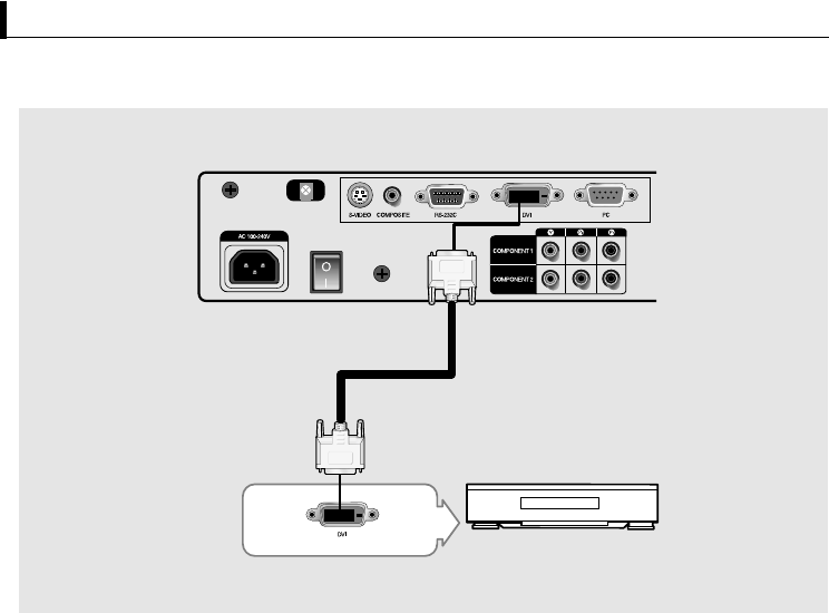
aConnect to the DVI terminal when you want to connect the projector with DTV, digital
satellite receiver, etc.
Connecting to Devices that have a DVI Terminal
Connect the DVI input terminal of your projector and the DVI output terminal of
the external device with a DVI cable.
21
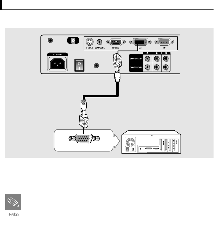
Connecting to a PC
Connect the PC input terminal of your projector and the Monitor output terminal
of your PC with a PC (D-SUB) cable.
● Make sure to turn off your projector and PC before connecting them.
After connecting the two, be sure to turn on the projector first and then the
PC.
● The RS-232C terminal is used for repair or software upgrades.
22
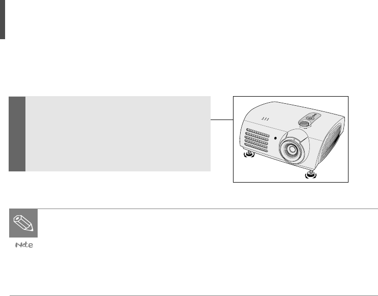
Installing Your Projector
Install your projector at a right angle to
the screen by adjusting the height
adjustment feet.
Move your projector slightly forward or
backward until the screen is clear.
● Adjust the lens toward the center of the screen. The screen may be dis-
torted or unclear if your projector is not installed at a right angle to the
screen.
● Do not install your projector in a bright place, as the screen may be not
seen clearly.
● Draw the curtains if your projector is installed in a bright place.
23
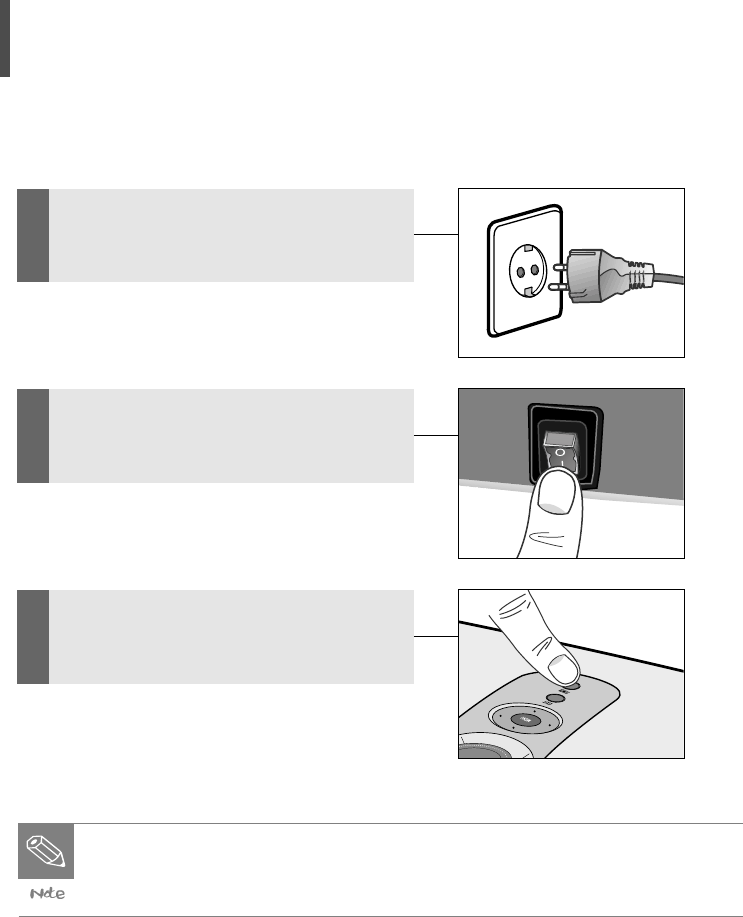
Powering On/Off
1Connect the power cord to a wall
outlet after connecting your projec-
tor to an external device.
2Press the "-" part of the switch on
the back of your projector.
3Press the POWER button on the top
of your projector or the POWER ON
button on the remote control.
● The cooling fan stops after about 90 seconds when the power is turned
off.
● Disconnect the power cord after the cooling fan has stopped.
24
Adjusting the Projector Feet
Adjust the screen position by turning
the height adjustment feet on your
projector.
● The position can be adjusted within about 5 degrees from the standard
position.
● The screen may be distorted when you adjust the projector height.
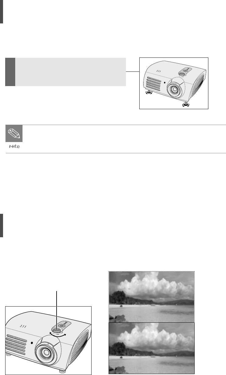
Using the Lens Shift Dial
You can move the lens up and down by turning the lens shift dial on the top of your
projector with your fingers.
Lens Shift Dial
UP DOWN
25
Installing Your Projector
Behind the Screen
You can use a translucent screen and
install your projector behind the
screen.
In this case, the images projected are
reversed.
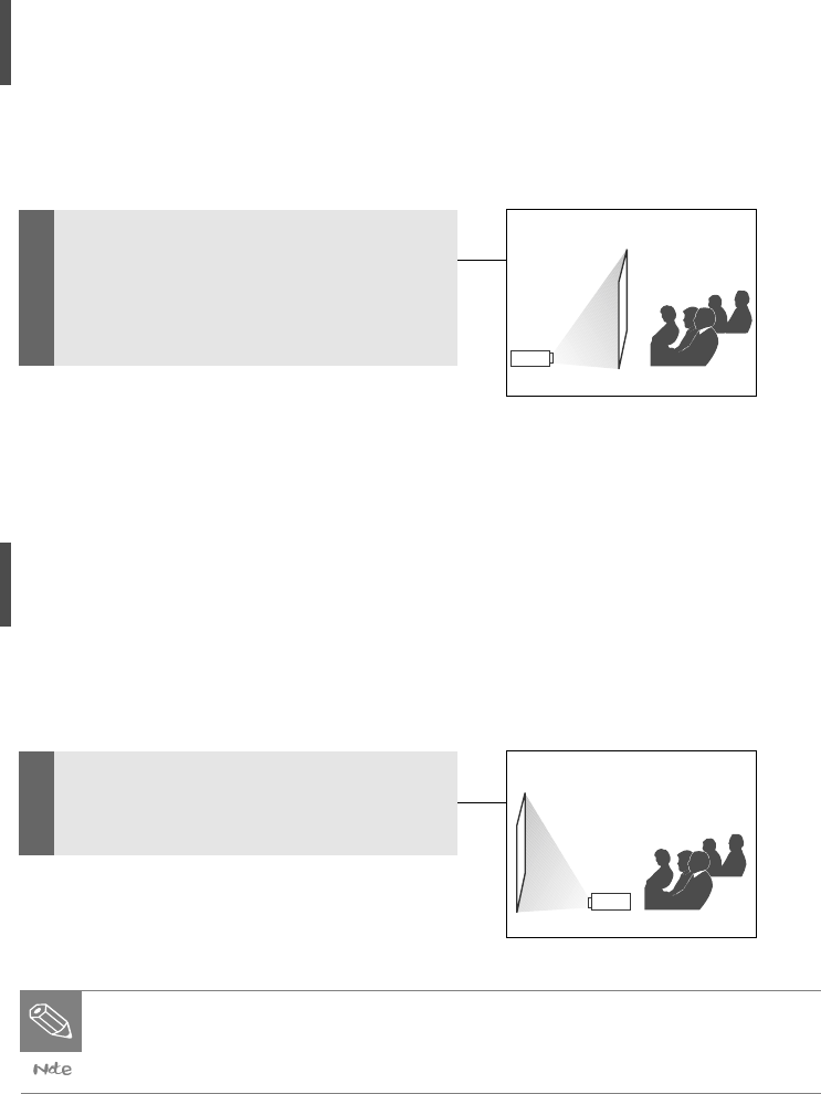
Installing Your Projector
In Front of the Screen
Install your projector in front of the
screen.
● You can hang your projector on the ceiling across from the screen.
● Contact an expert to install your projector using brackets when installing it
on the ceiling.
26
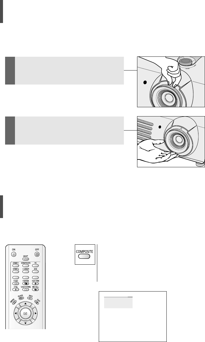
Using the Zoom and Adjusting Focus
Zoom-in/out using the zoom control and Focus using the diaphragm.
1Zoom-in or out by turning the zoom
control.
2Adjust the Focus by turning the
diaphragm.
Selecting an External Device
Select the desired external device by pressing
the Input button on the remote control or the
Source button on your projector.
The message "No input signal" is displayed when
there is no external device connected.
COMPOSITE
27
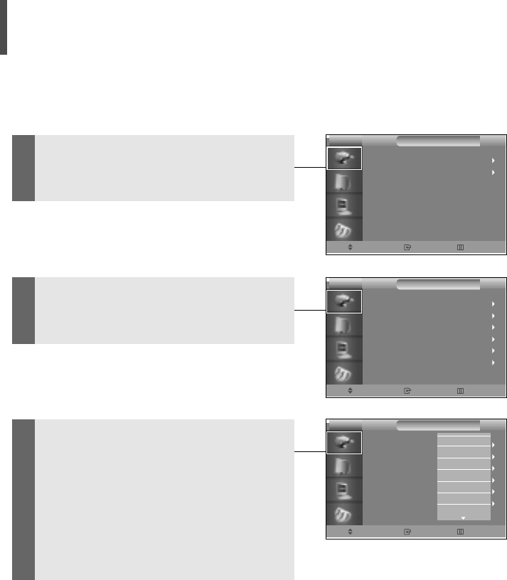
Editing Input Device
Names
1Press the Menu button and select
INPUT.
Move Enter Exit
INPUT
Input Source
Edit Name
PROJECTOR
2Select the Edit Name menu from the
INPUT menu.
3
Select an item (Component1,
Component2, or S-Video...) from the
Edit Name menu and select the name of
device connected. Repeat for all items
on the menu.
Press the Menu button again and the
menu screen will disappear.
Move Enter Return
INPUT
Component1
Component2
S-video
Composite
PC
DVI
: _ _ _ _
: _ _ _ _
: _ _ _ _
: _ _ _ _
: _ _ _ _
: _ _ _ _
PROJECTOR
Move Enter Return
INPUT
PROJECTOR
Component1
Component2
S-video
Composite
PC
DVI
: _ _ _ _
: _ _ _ _
: _ _ _ _
: _ _ _ _
: _ _ _ _
: _ _ _ _
_ _ _ _
VCR
DVD
Cable STB
HD STB
Satellite STB
AV Receiver
28
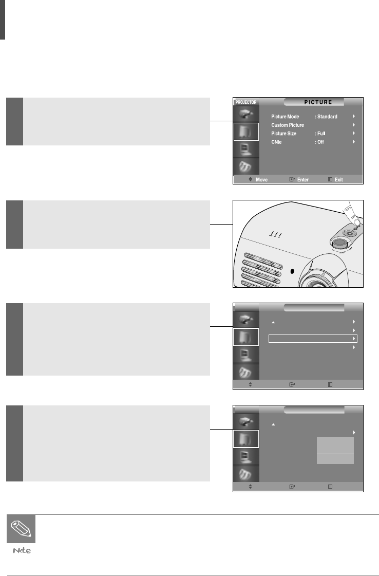
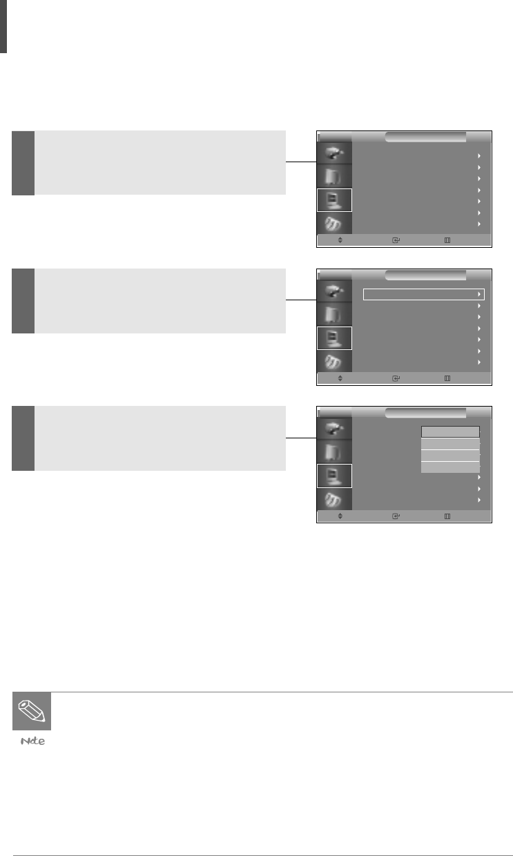
Gamma Compensation
This function provides higher picture quality by brightening the dark part of picture.
1Press the Menu button and select
Picture.
2Select Custom Picture using the Up(
…
)
or Down(
†
) button on the Picture menu.
3Select Gamma using the Up(
…
) or
Down(
†
) button while in Custom Picture
mode.
Select More to display the Gamma
menu.
4Select your desired mode among
Gamma1, Gamma2, and Gamma3 using
the Up(
…
) or Down(
†
) button while in
Gamma mode.
Gamma Mode
● Gamma 1: Brightens the dark part of picture more effectively.
● Gamma 2: Emphasizes the dark part of picture by making it darker.
● Gamma 3
Move Enter Return
PICTURE
More
Color Temperature
Gamma
Save
: Gamma Mode 1
PROJECTOR
Move Enter Return
PICTURE
More
Color Temperature
Gamma
Save
PROJECTOR
: Gamma Mode 1
Gamma Mode 2
Gamma Mode 3
29
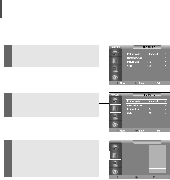
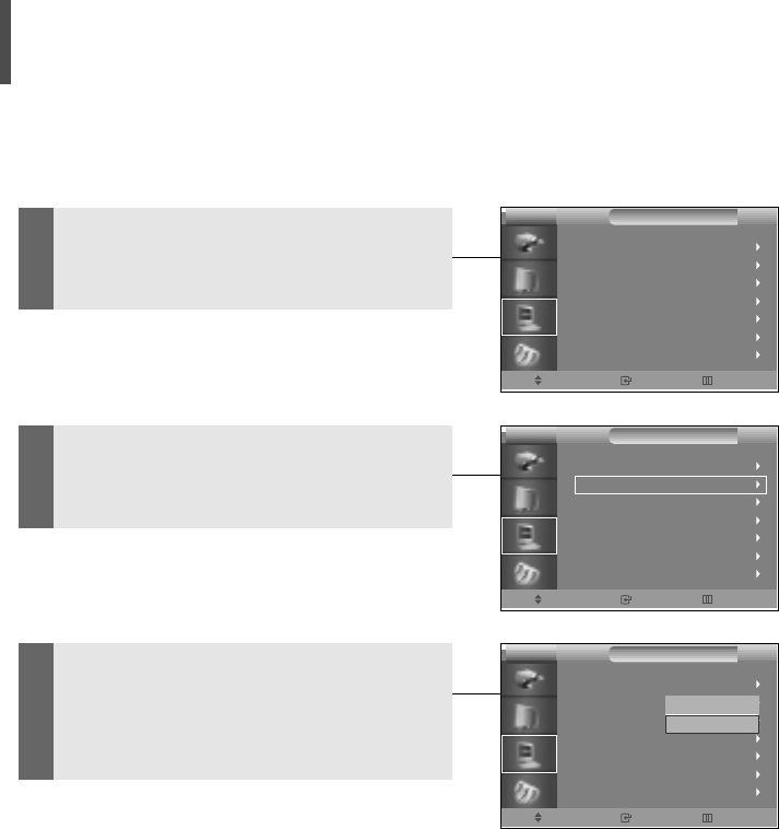
Setting Screen Modes
1Press the Menu button and select
Picture.
2Select the Picture Mode menu using
the Up(
…
) or Down(
†
) button while in
the PICTURE menu.
2Select your desired mode among
Standard, Dynamic, Movie1, etc... using
the Up(
…
) or Down(
†
) button while in
the Picture Mode menu.
Move Enter Return
PICTURE
Picture Mode
Custom Picture
Picture Size
DNle
: Custom
: Full
: Off
PROJECTOR
Standard
Dynamic
Movie 1
Movie 2
User 1
User 2
User 3
Custom
30
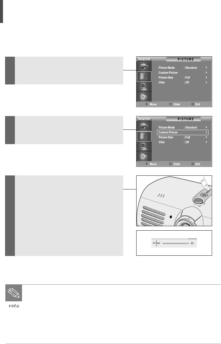
Customizing Screen Modes
1Press the Menu button and select
Picture.
2Select Custom Picture using the Up(
…
)
or Down(
†
) button on the Picture
menu.
3
Select your desired item(s) among
Contrast, Brightness, Sharpness, etc . . .
using the Up(
…
) or Down(
†
) button
while in the Custom Picture menu, and
adjust it to your desired level.
Use the Left(◀) or Right(▶) button to
control each item.
Screen Modes
● Contrast: Adjusts darkness and brightness differences between objects
and background.
● Brightness: Adjusts the brightness of the entire screen.
● Sharpness: Adjusts the outline clarity of objects.
● Color: Adjusts the color depth to make it lighter or deeper.
● Tint: Allows you to adjust the color of objects to a more natural color.
31
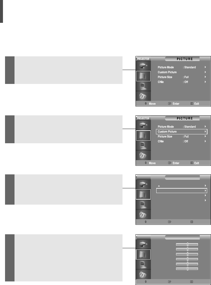
Adjusting Color Temperature
Adjusts the color temperature according to the type of image input into the projector.
1Press the Menu button and select
Picture.
2Select Custom Picture using the Up(
…
)
or Down(
†
) button on the Picture
menu.
3Select Color Temperature using the
Up(
…
) or Down(
†
) button while in the
Custom Picture menu.
4Select each separately: R-Gain, G-Gain
or B-Gain using the Up(
…
) or Down(
†
)
button while in the Color Temperature
menu, and adjust it to an appropriate
value.
Move Enter Return
PICTURE
R-Gain
G-Gain
B-Gain
R-Offset
G-Offset
B-Offset
0
0
0
0
0
0
PROJECTOR
Move Enter Return
PICTURE
More
Color Temperature
Gamma
Save
: Gamma Mode 1
PROJECTOR
32
Image Projection Method
You can view screen images in Reverse mode (image projected in reverse) or Inverse
mode (image projected from the opposite side).
1Press the Menu button and select the
SETUP menu.
2Select the Install menu using the Up(
…
)
or Down(
†
) button while in the SETUP
menu.
3Select your desired image projection
mode from the Install menu using the
Up(
…
) or Down(
†
) button.
Image Projection Modes
Mode Item Description
Front Floor Front Normal Screen
Front Ceiling Front + Ceiling Reverse Mode (Image projected in reverse)
Rear Floor Rear Inverse Mode (Image projected from the
back of screen
Rear Ceiling Rear + Ceiling Reverse Inverse Mode (Image projected in
reverse from the rear of screen)
Move Enter Exit
SETUP
Install
Light Setting
Vertical Keystone
Test Pattem
PC
Factory Default
Information
: Rear-Celling
: Theater
PROJECTOR
Move Enter Exit
SETUP
Install
Light Setting
Vertical Keystone
Test Pattem
PC
Factory Default
Information
: Rear-Celling
: Theater
PROJECTOR
Move Enter Return
SETUP
Install
Light Setting
Vertical Keystone
Test Pattem
PC
Factory Default
Information
PROJECTOR
Front-Floor
Front-Celling
Rear-Floor
Rear-Celling
33
Setting Up the Theater Function
You can watch the screen in Theater mode by adjusting the quantity of light.
1Press the Menu button and select the
SETUP menu.
2Select the Light Setting menu using the
Up(
…
) or Down(
†
) button while in the
SETUP menu.
3Select Theater from the Light Setting
menu using the Up(
…
) or Down(
†
) but-
ton.
Move Enter Exit
SETUP
Install
Light Setting
Vertical Keystone
Test Pattem
PC
Factory Default
Information
: Rear-Celling
: Theater
PROJECTOR
Move Enter Exit
SETUP
Install
Light Setting
Vertical Keystone
Test Pattem
PC
Factory Default
Information
: Rear-Celling
: Theater
PROJECTOR
Move Enter Return
SETUP
Install
Light Setting
Vertical Keystone
Test Pattem
PC
Factory Default
Information
: Rear-Celling
: Theater
PROJECTOR
Standard
Theater

ISUAL REALISM
Lamp LED Indicators................35
Replacing the Lamp ................36
Cleaning the Air Filter ..............37
Troubleshooting ......................38
Specifications ........................39
3
Troubleshooting and Other Information
35
● The warning LED indicator notifies you when a problem occurs inside the projector.
● The TEMP LED indicator turns on when the projector generates too much heat.
● The LAMP LED indicator turns on when you should replace the lamp.
Lamp LED Indicators
● If a warning LED indicator turns on, please use the projector only after it has
completely cooled down (please wait for more than 5 minutes).
● When the power is turned off and on, the lamp LED indicators may blink in
order to prevent the loss of power consumption.
In this case, disconnect the power cord from the power outlet and reconnect
it.
● Please contact a service center or product distributor when the lamp is bro-
ken.
● Do not remove the lamp immediately after using your projector. Please dis-
connect the power cord and wait 1 hour before replacing the lamp, as it will
have heated up during use.
LED Indicator Cause Symptom Action
TEMP LED The internal Air is not flowing Move your projector to a
Indicator temperature is into your projector. well-ventilated place.
high. Air filter is full. Clean the filter.
Cooling fan is Please contact a service
out of order. center or product distributor.
Internal circuit has
failed.
LAMP LED The lamp does The lamp has Please replace the lamp.
Indicator not turn on. burned out. Please contact a service
The lamp circuit is center or product distributor.
out of order.
The lamp should The lamp has been
be replaced. used for more than
1,900 hours.
Common Troubles and Actions
Lamp LED Indicators
36
1. Turn off the projector.
Press the Power button and wait until the cooling fan has stopped.
2. Disconnect the power cord.
3. Remove the lamp gauge cover.
Unfasten the lamp gauge cover screws on the back of projector, and take the
cover off.
4. Disconnect the power cord.
Unfasten the screws securing the lamp gauge and pull the lamp gauge out to the
front.
5. Insert a new lamp gauge.
Make sure to push the lamp gauge in until it is in place, and then re-fasten the
screws.
6. Close the lamp gauge cover
Close the projector cover and re-fasten the screws
7. Connect the power cord.
8. Turn on the projector and initialize the lamp time.
Replacing the Lamp
● Be careful not to touch the inside of the projector or the lamp gauge.
● Make sure to work only with your hands (do not insert foreign objects into the
projector).
● Make sure to turn off the main power and disconnect the power cord before
replacing the lamp.

37
● One air filter has been installed inside the projector to optimize operating time.
● Clean the air filter periodically using a vacuum cleaner.
● Clean the air filter every 100 hours.
● Clean the air filter more often if it is used in a dusty or smoky place.
Cleaning the Air Filter
1. Disconnect the power cord.
2. Insert the hose of vacuum cleaner into the drainpipe of the air filter, and remove
the dust.
Cleaning Procedure

38
Symptom Action
The Screen does not display. •Check whether the power cord of the projector
is disconnected.
•Check whether the input selection is correct.
•Check whether the cables on the back of the
projector are connected correctly.
•Check whether the remote control batteries
have run out.
•Make sure that Color or Brightness has not
been set to minimum.
The Color is not good. •Check whether Tint or Contrast is adjusted
correctly.
The Picture is faint. •Adjust the focus.
•Make sure that the projection distance is not
too short or long for the focus.
The OSD is not displayed. •The Display mode is set to Level A or Level B
in order to prevent a part or whole of the
screen from being displayed.
A Strange Noise is coming •When the screen is normal, noise may occur
from the projector. when the cabinet contracts and expands due
to temperature changes.
• It does not affect product quality and
performance.
• The Lamp LED indicator is turned on.
• Refer to Lamp LED Indicators.
A Noise Line appears • Adjust the horizontal noise setting.
on the screen. • Noise may appear when your projector works
with a computer.
• Set the noise filter to On using RS-232C.
A Green Color appears • Change the input signal type.
on the Input Signal Indicator.
Troubleshooting
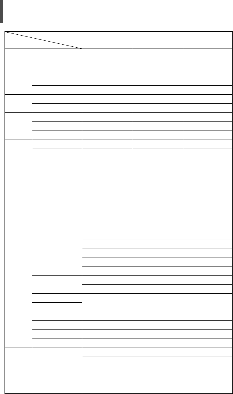
39
Panel
Lamp
Color
Wheel
전원
Dimension
(mm)
Weight
(Kg)
Accessory
Features
Rear
In/Out
Terminals
Environment
Size
Resolution
Type
Life
Size
Type
Consumption
AC Input Range
Frequency
Set Only
Packing
Set Only
Packing
Brightness
Contrast
Screen Size
Projection Distance
Keystone
DVI
PC
Component 1
Component 2
S-Video
Composite
RS-232C
Temp. & Humidity
Safety
Noise(Standard Mode)
Noise(Theater Mode)
0.87"
1280 × 720
250W UHP
(BY PHILIPS)
2000Hrs
55mm
6 Segment
350W
100V~240V
50~60Hz
384×425×177
460×515×290
9
11.6
800 ANSI
1800:1
Vertical
32dB
32dB
0.87"
1280 × 720
250W UHP
(BY PHILIPS)
2000Hrs
55mm
6 Segment
350W
100V~240V
50~60Hz
384×425×177
460×515×290
9
11.6
800 ANSI
3000:1
Vertical
32dB
32dB
0.87"
1280 × 720
250W UHP
(BY PHILIPS)
2000Hrs
55mm
6 Segment
350W
100V~240V
50~60Hz
384×425×177
460×515×290
9
11.6
??? ANSI
????:1
Vertical
32dB
32dB
Specifications
Owner's Instruction, Power Cord, Remote control, Signal Cable
Diagonal 33~300 Inch
1140~13645 mm
1) Connector Type: DVI-D
2) Available Format
PC: VGA~SXGA
DTV: 480p, 720p, 1080i
3) Timing: Refer to Table 1 (PC & DTV Timing)
1) Connector Type: 15Pin D-Sub
2) Timing: Refer to Table 1 (PC & DTV Timing)
1) Signal Type: YPbPr
2) Available Format: 480i, 480p, 720p, 1080i
3) Timing: Refer to Table 1 (PC & DTV Timing)
Available TV System: NTSC, NTSC4.43,
PAL(B/G, D/K, M, N, I), SECAM(B/G, D/K, I, L)
Only for Service
Operating: Temp. (0~40), Humidity(20~80%)
Storage: Temp. (-10~50), Humidity(20~80%)
Class B
Model
Classification SP-H700 SP-H800 SP-Hxx