Samsung Electronics Co SPI-2210012502 Mobile WiMAX Indoor RAS User Manual
Samsung Electronics Co Ltd Mobile WiMAX Indoor RAS
UserManual.wiki
>
Samsung Electronics Co
>
SPI 2210012502 User Manual
User Manual
Navigation menu
Upload a User Manual
Namespaces
Wiki Guide
HTML
PDF
Info
Views
User Manual
Discussion / Help
Navigation
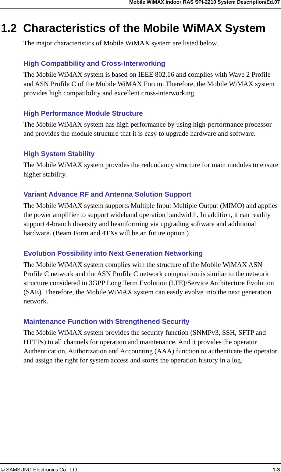
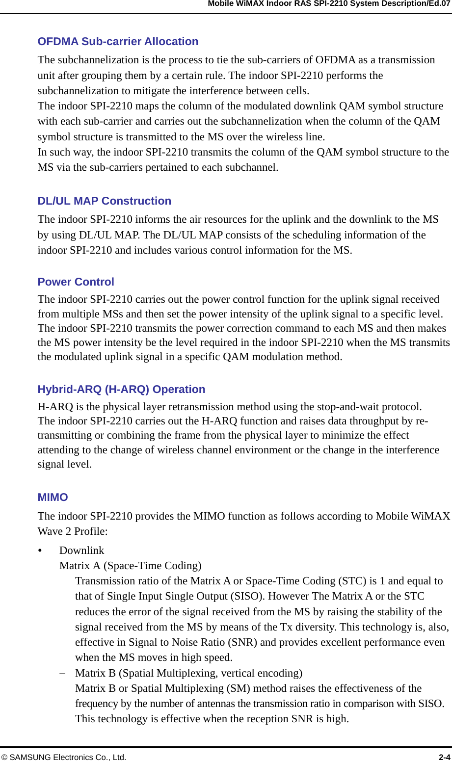
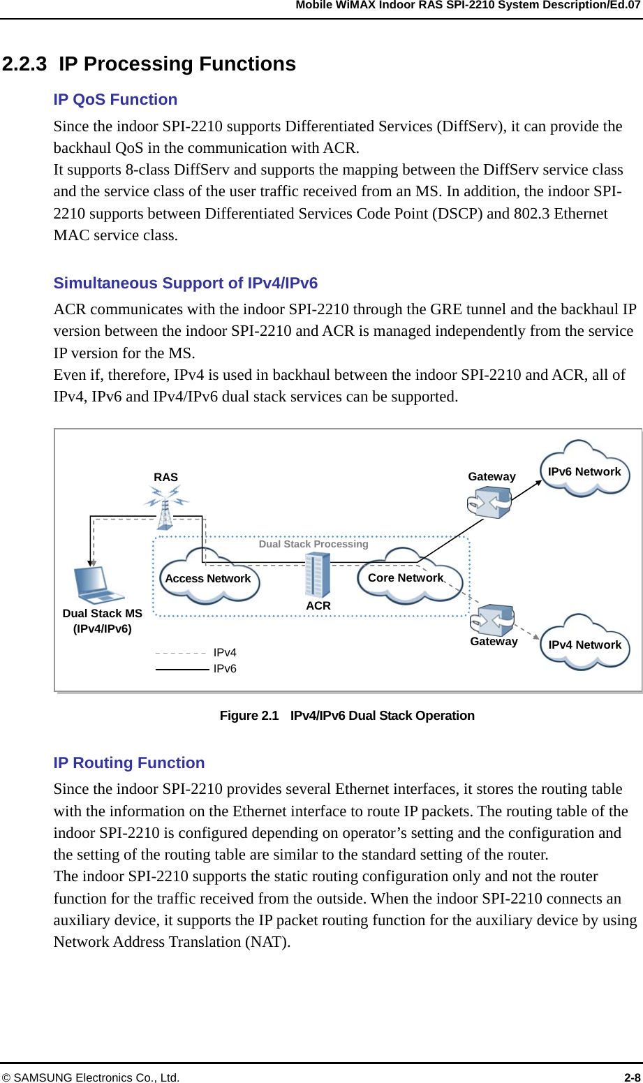


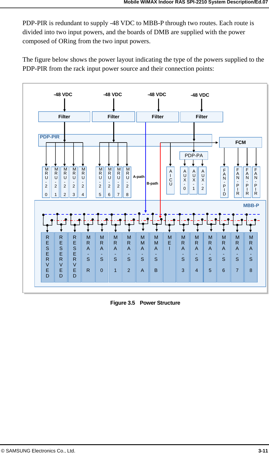
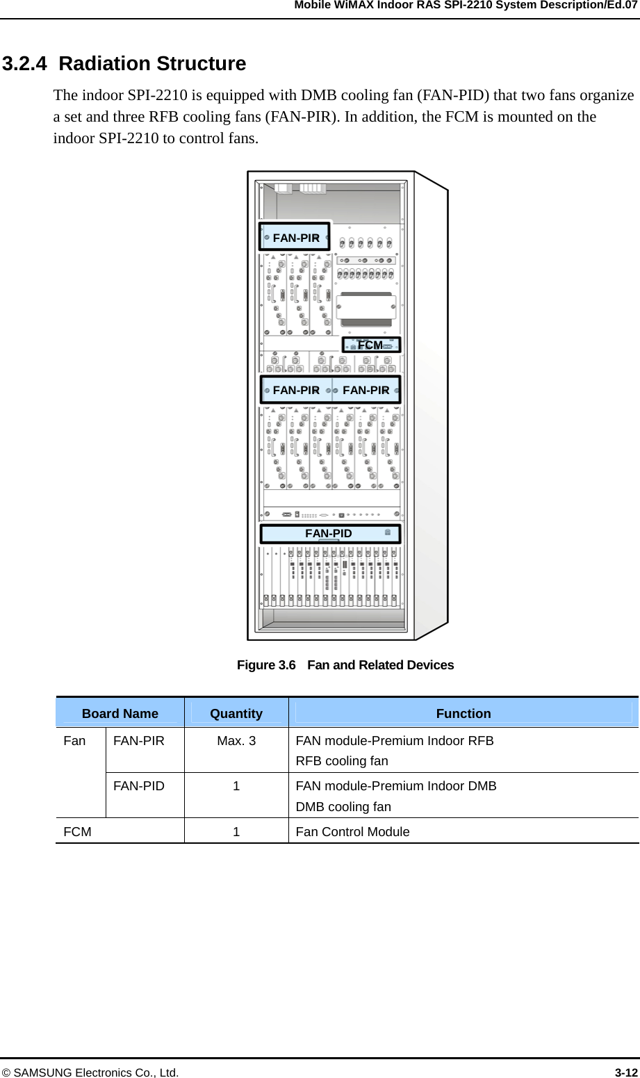
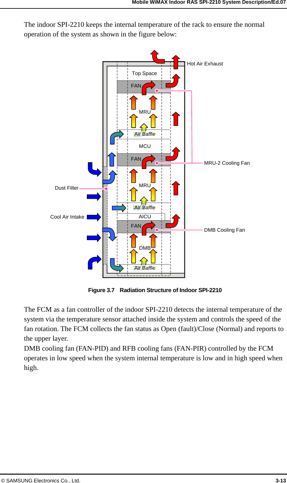
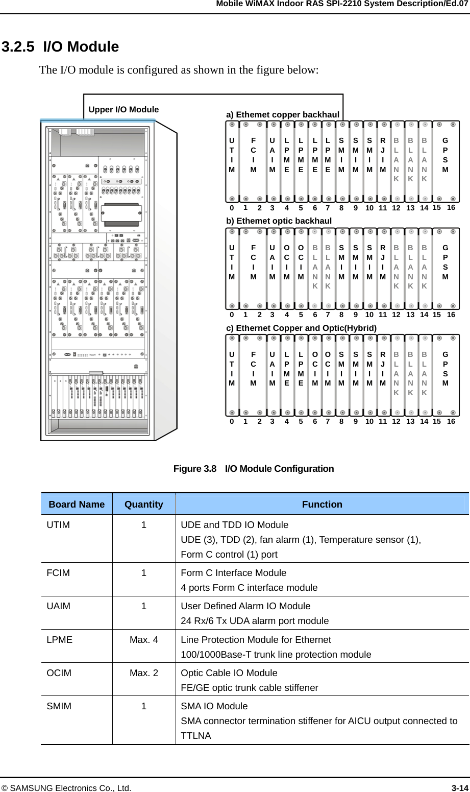
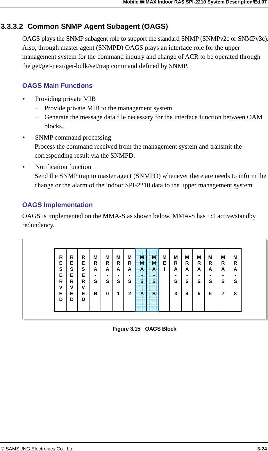
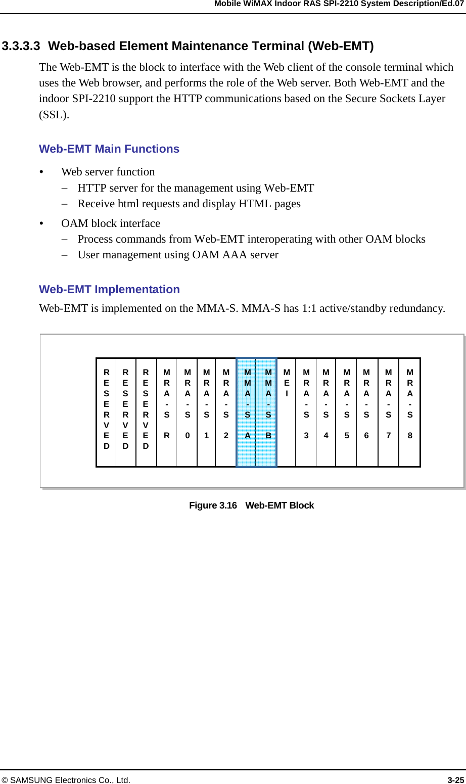
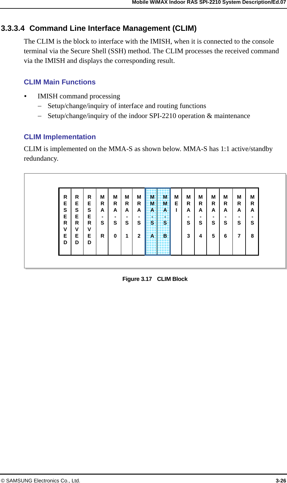
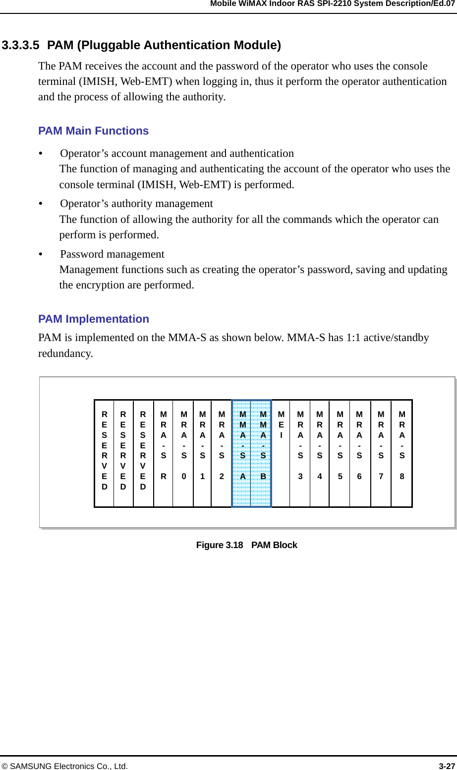
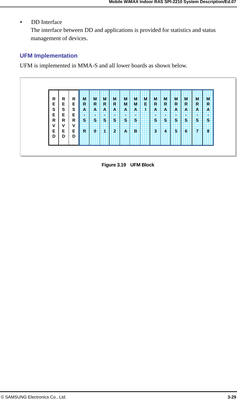
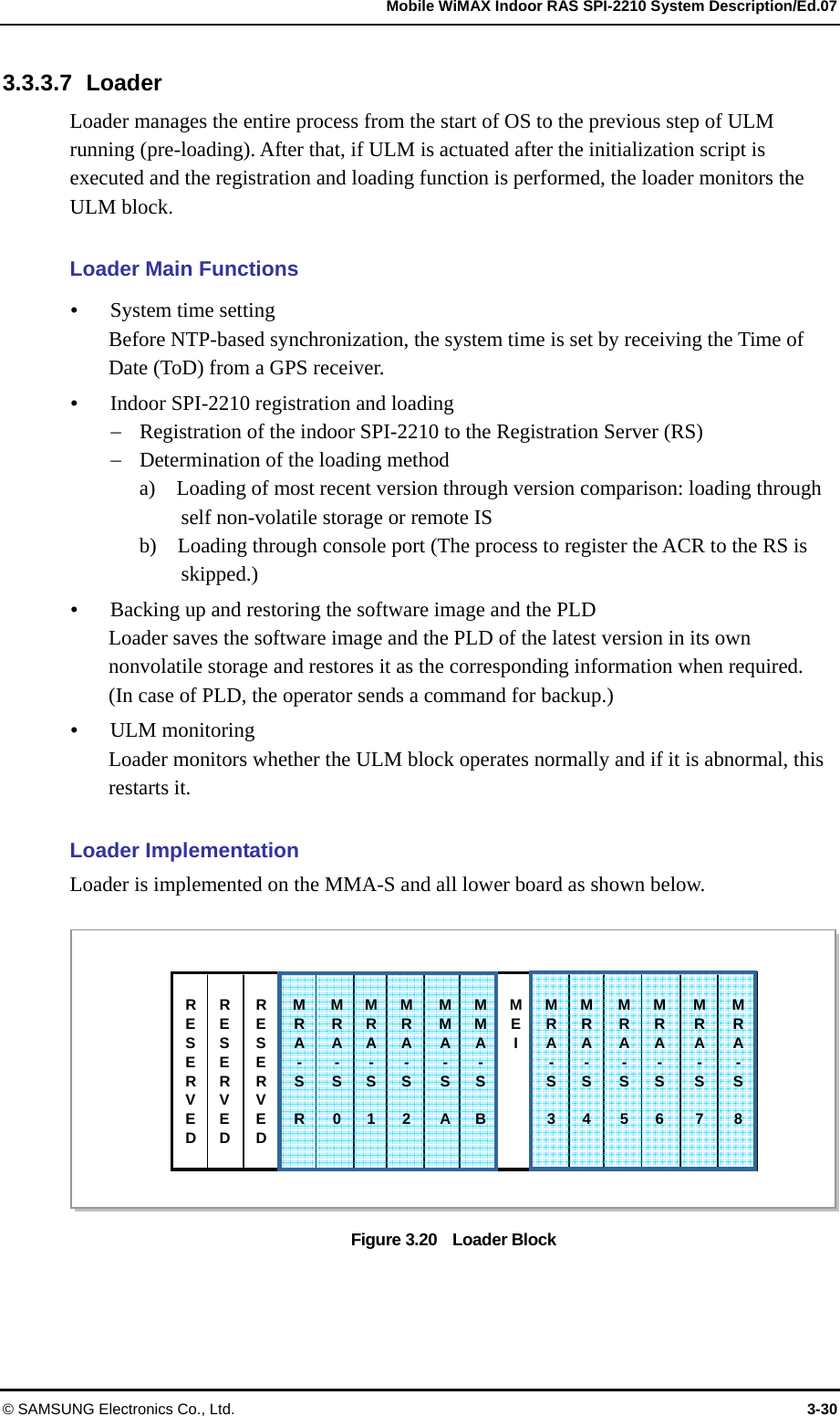
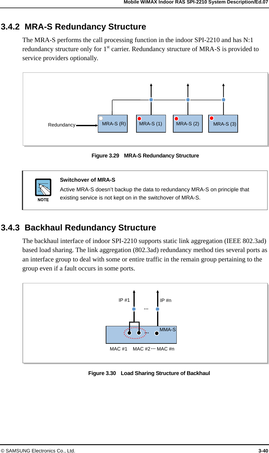
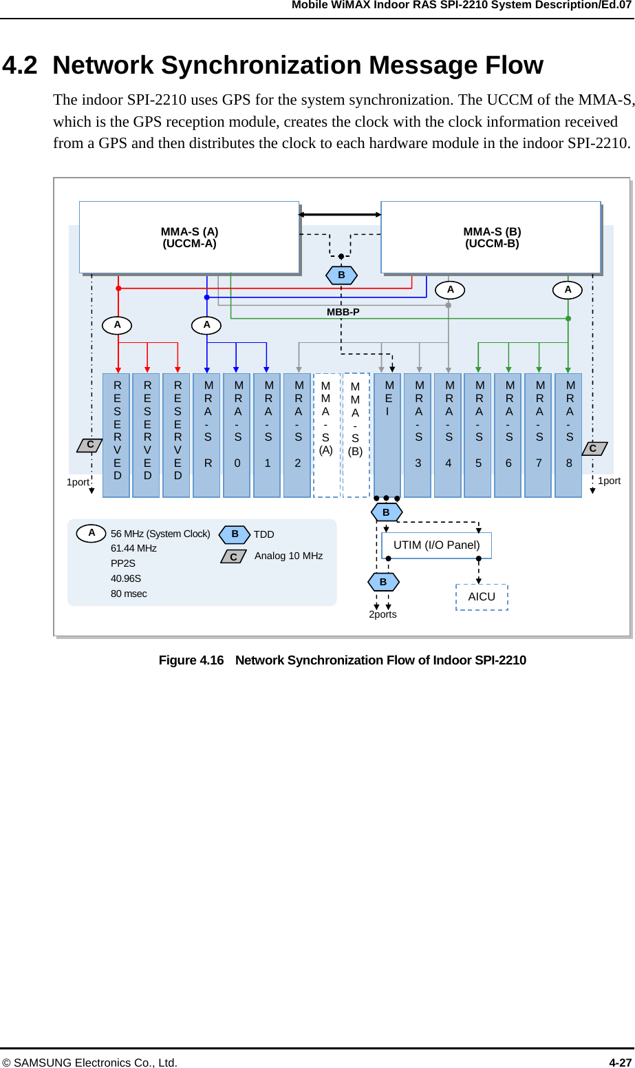
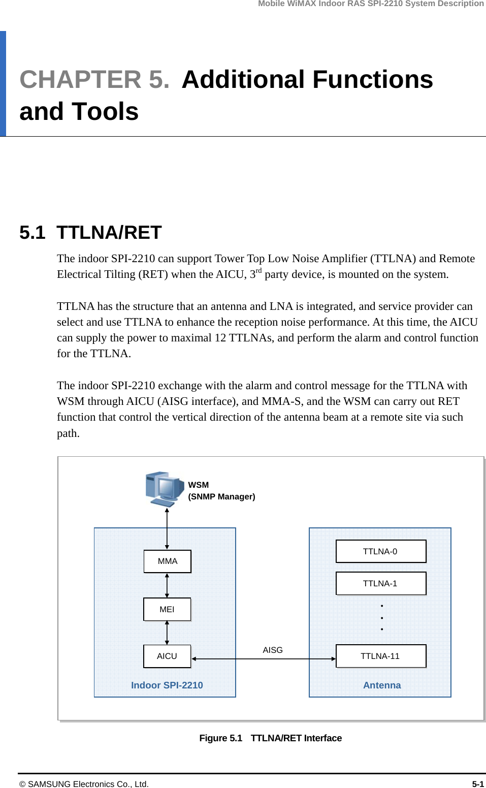
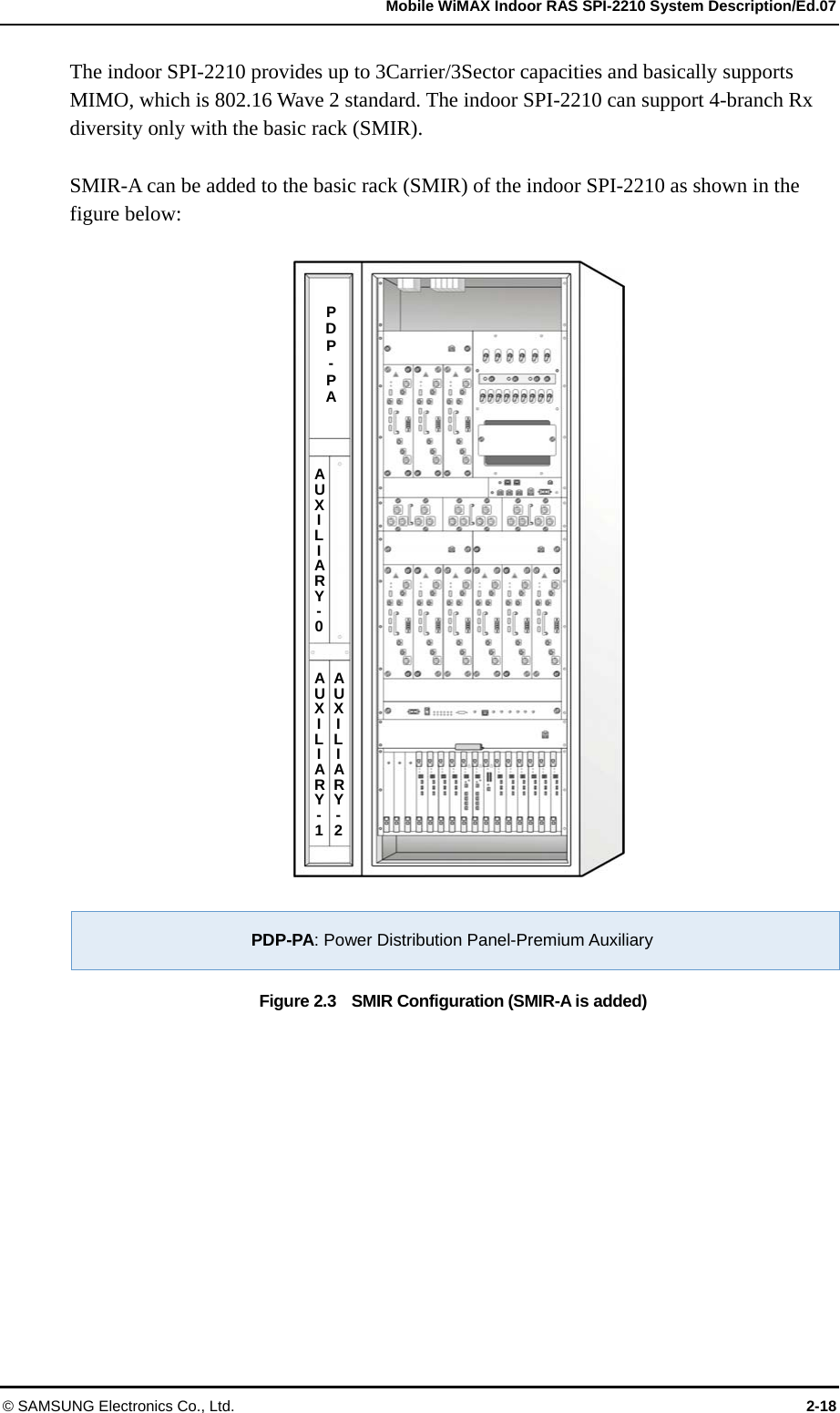
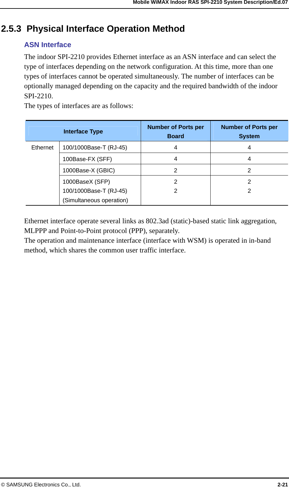
![Mobile WiMAX Indoor RAS SPI-2210 System Description/Ed.07 © SAMSUNG Electronics Co., Ltd. 2-17 2.4 System Configuration The indoor SPI-2210 is basically composed of SMIR and SMIR-A is added to the basic rack to mount an auxiliary device when service provider’s auxiliary device exists. y Samsung Mobile WiMAX base station Indoor Rack (SMIR) Basic rack of the indoor SPI-2210 y Samsung Mobile WiMAX base station Indoor Rack-Auxiliary (SMIR-A) Separate rack to mount an auxiliary device (optional) FAN-PIR: FAN-Premium Indoor RFB RFB: RF Block PDP-PIR: Power Distribution Panel-Premium Indoor Redundancy FCM: Fan Control Module AICU: Antenna Interface Control Unit FAN-PID: FAN-Premium Indoor DMB DMB: Digital Main Block Figure 2.2 SMIR Configuration [Close Door] [Open Door] RFB RFB FAN-PIR FAN-PIR PDP-PIR AICU FAN-PID DMB FCM FAN-PIR](https://usermanual.wiki/Samsung-Electronics-Co/SPI-2210012502/User-Guide-1255317-Page-40.png)

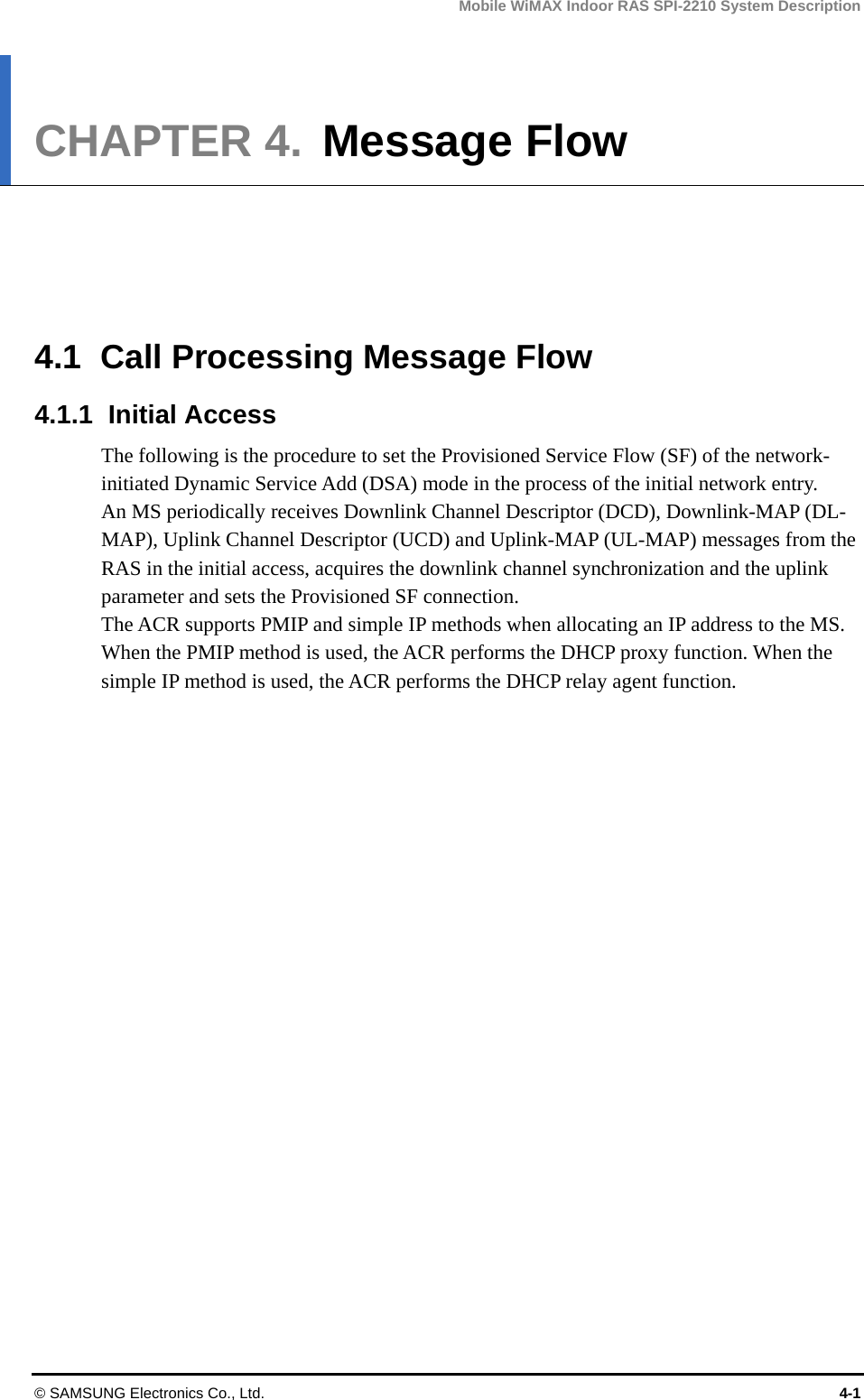
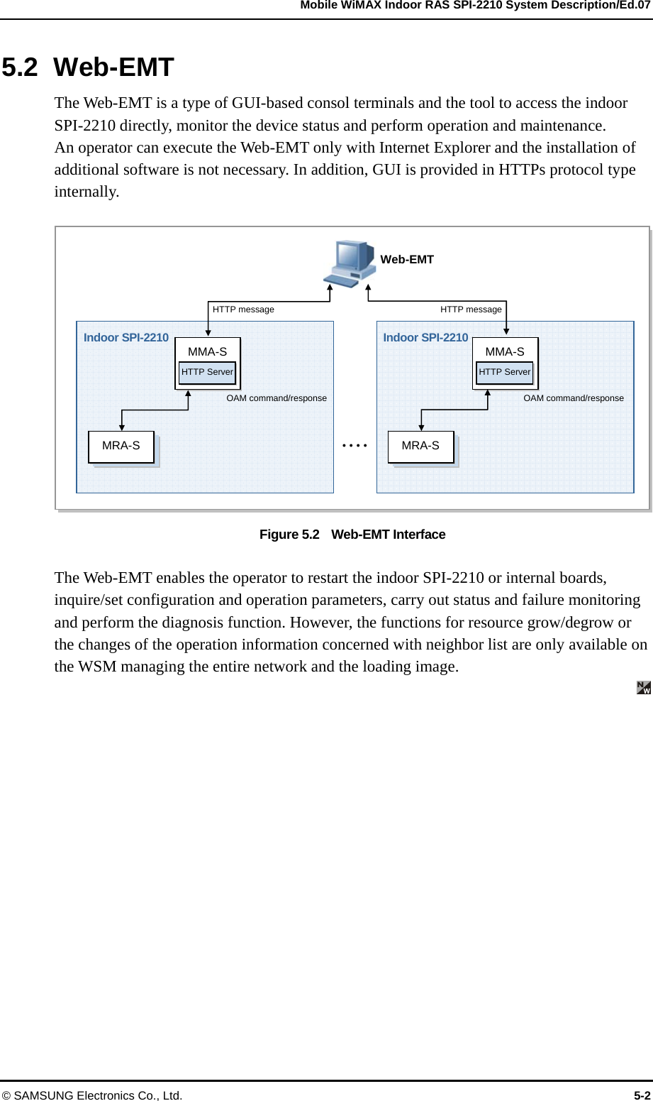
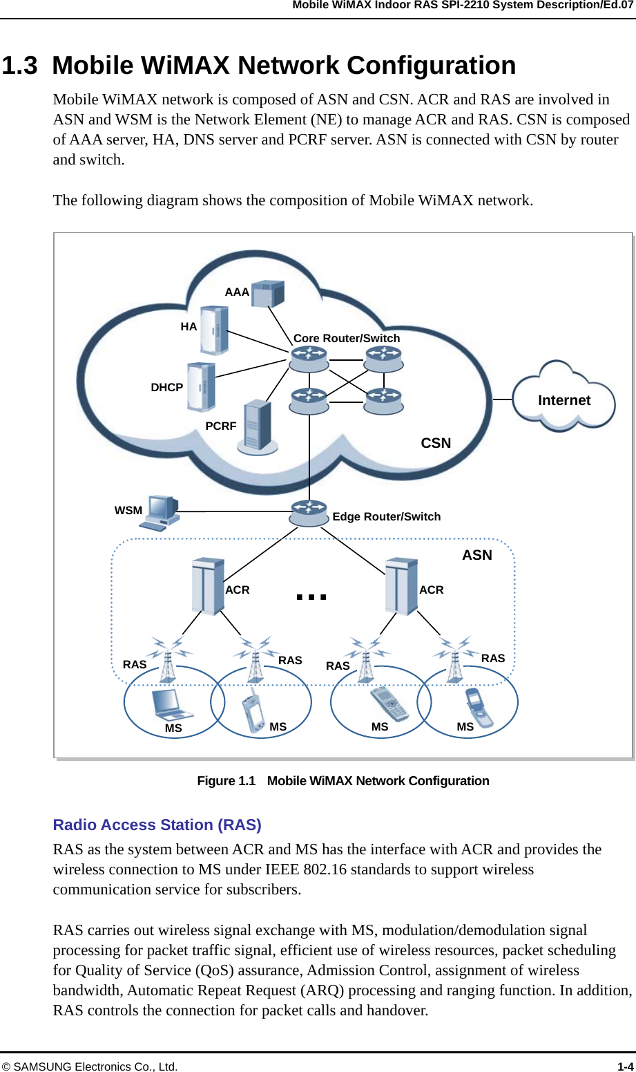
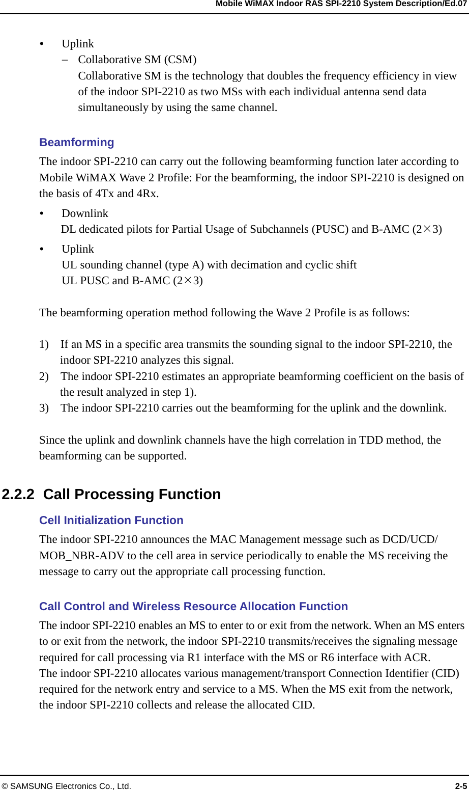
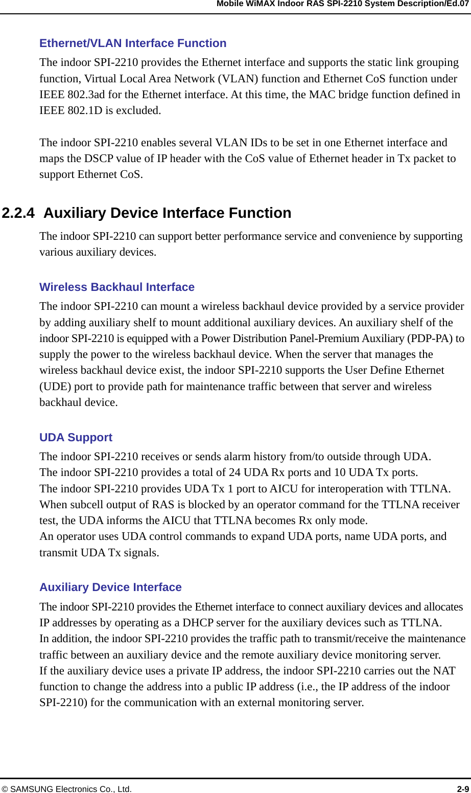
![Mobile WiMAX Indoor RAS SPI-2210 System Description/Ed.07 © SAMSUNG Electronics Co., Ltd. 3-5 Mobile WiMAX base station Main control board Assembly-Standard (MMA-S) The MMA-S carries out the main processor function and the GPS reception function. The MMA-S has the redundancy configuration for reliability. y Main Processor Function The MMA-S is the board that carries out the role as the highest layer in the indoor SPI-2210 and is equipped with the main processor. The main processor of the MMA-S performs the functions, such as communication path setting between MS and ACR, Ethernet switch function in the indoor SPI-2210, system operation and maintenance and TDD signal control. The MMA-S manages the status of all hardware and software in the indoor SPI-2210 and reports each status information to WSM via ACR. In addition, the MMA-S allocates and manages the resources of the indoor SPI-2210 and the connection of the MMA-S and a PC for the Web-EMT enables to maintain the indoor SPI-2210 with no interworking with ACR. The MMA-S has the redundancy configuration of active/standby to allow the standby MMA-S to replace the function of the active MMA-S when a fault occurs in the active MMA-S. y GPS Reception and Clock Distribution Function The MMA-S is equipped with Universal Core Clock Module (UCCM) for GPS reception. The UCCM enables each block of the indoor SPI-2210 to be operated in the synchronized clock system. The UCCM mounted on the MMA-S creates the system clocks[56 MHz, 12.5 Hz (80 msec), PP2S, analog 10 MHz, 61.44 MHz] by using the reference signal received from a GPS and distributes them to the hardware blocks in the system. These clocks are used to maintain the internal synchronization of the indoor SPI-2210 and operate the system. If no GPS signal is received due to a fault, the UCCM carries out the holdover function to provide the normal clock for a certain time as provided in the existing system. In addition, if a fault occurs in the UCCM of the active MMA-S, the redundancy status between the UCCMs of the active MMA-S and the standby MMA-S is switched and then the redundancy status between MMA-Ss is, also, switched immediately. y Network Interface Function The MMA-S interfaces with an ACR in Gigabit Ethernet or Fast Ethernet method. At this time, the Ethernet interface with the ACR is duplicated in the link aggregation method. The MMA-S can provide maximum two Gigabit Ethernet ports or four Fast Ethernet ports per board, and support the link aggregation redundancy method. The MMA-S can be divided as follows depending on the interface types provided by MMA-S, and service provider can choose the interface type.](https://usermanual.wiki/Samsung-Electronics-Co/SPI-2210012502/User-Guide-1255317-Page-50.png)