Samsung Electronics Co SPI-2L10022500 Mobile WiMAX Outdoor RAS User Manual
Samsung Electronics Co Ltd Mobile WiMAX Outdoor RAS
UserManual.wiki
>
Samsung Electronics Co
>
SPI-2L10022500 User Manual
>
user manual
Contents
1.
user manual
2.
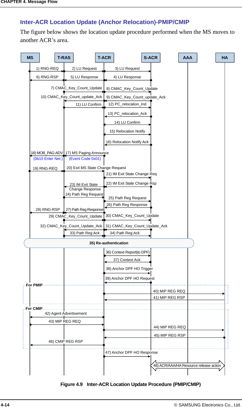
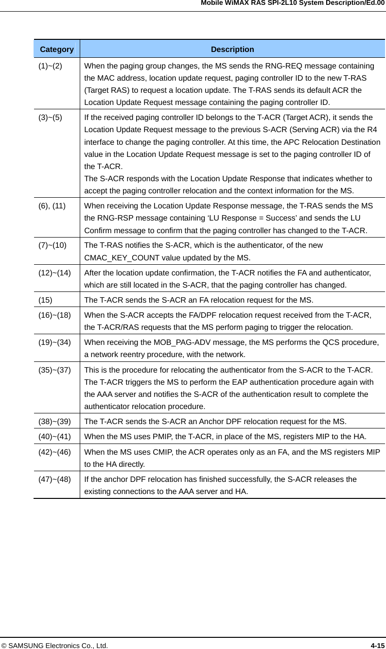
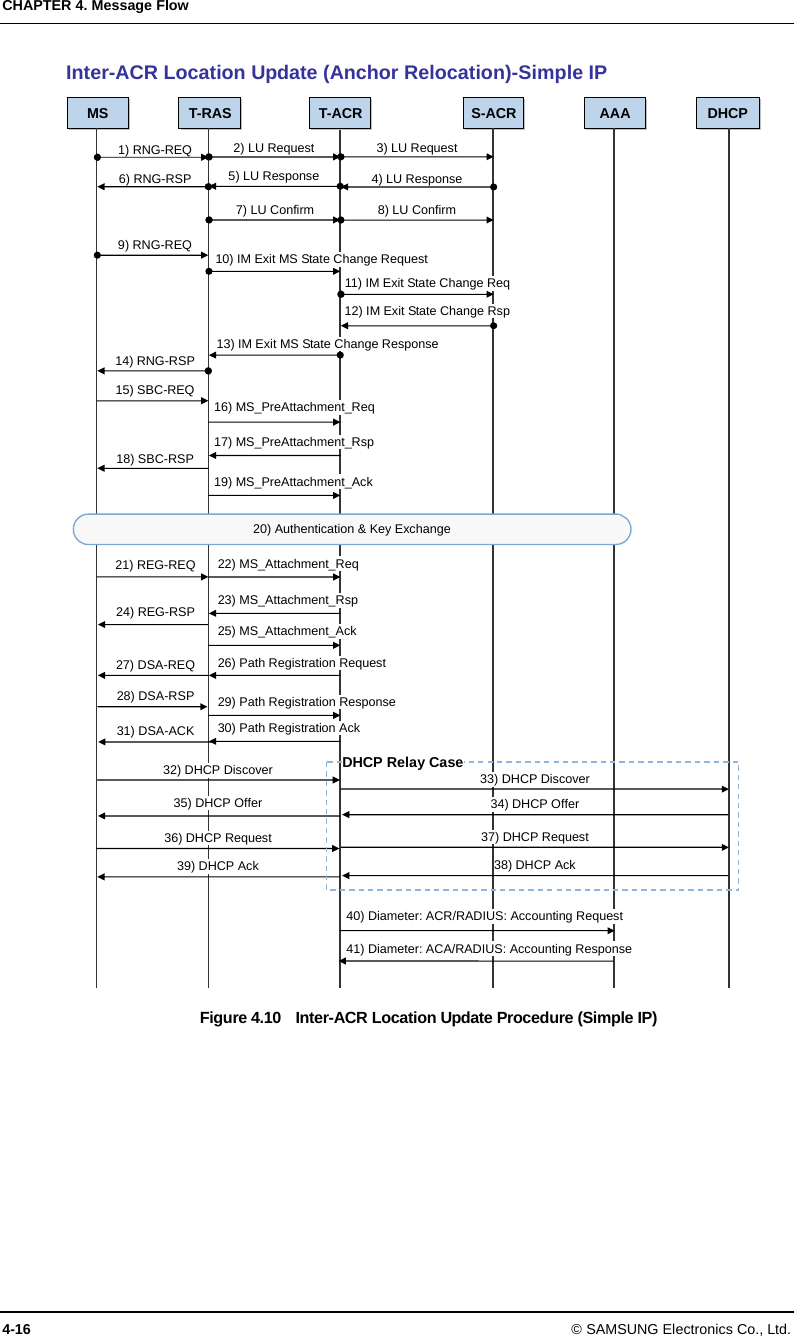
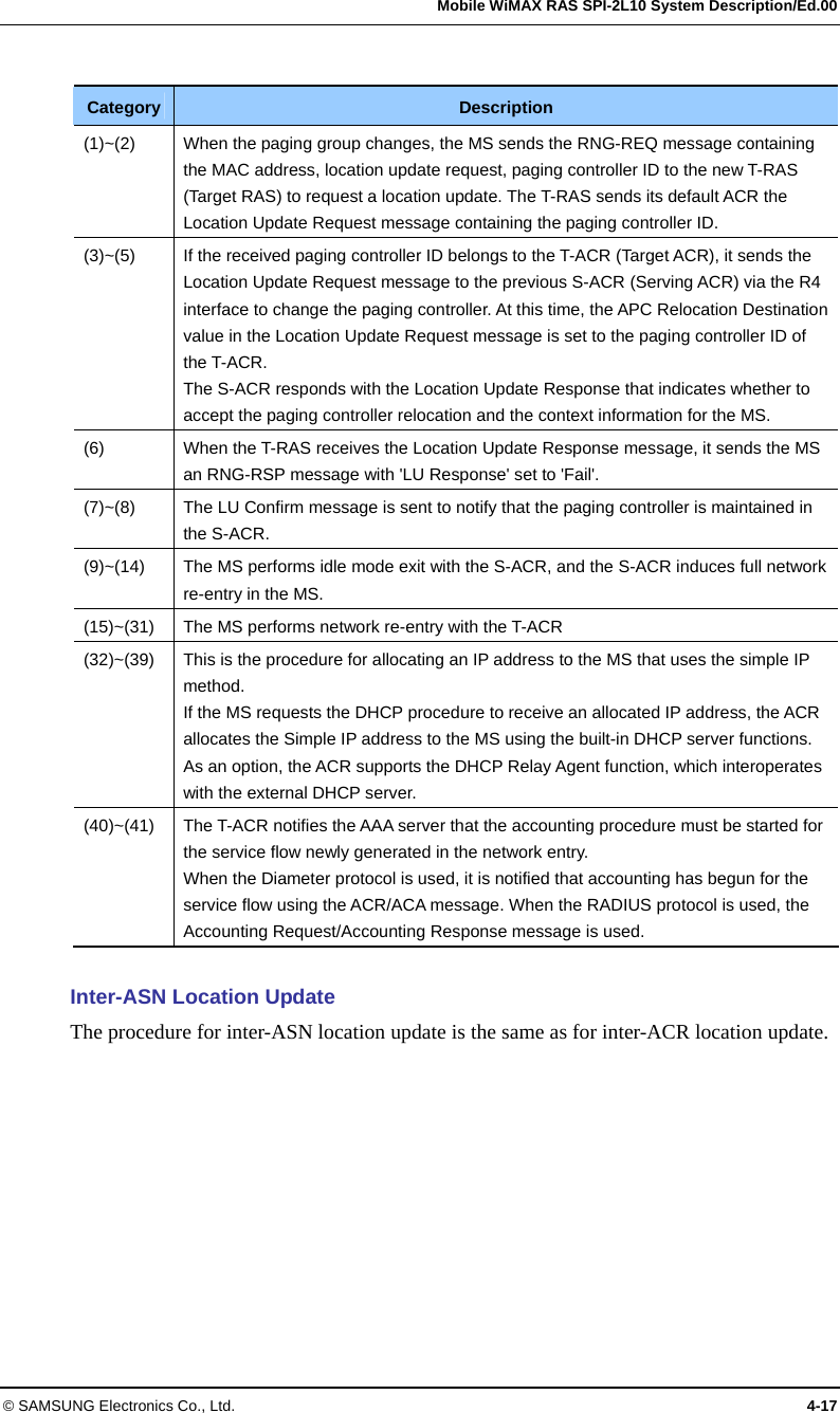
User Manual
user manual
Navigation menu
Upload a User Manual
Namespaces
Wiki Guide
HTML
PDF
Info
Views
User Manual
Discussion / Help
Navigation