Samsung Electronics Co SWLN01 Wireless LAN Mini PCI Card with SM MIMO User Manual
Samsung Electronics Co Ltd Wireless LAN Mini PCI Card with SM MIMO Users Manual
UserManual.wiki
>
Samsung Electronics Co
>
SWLN01 User Manual
Users Manual
Navigation menu
Upload a User Manual
Namespaces
Wiki Guide
HTML
PDF
Info
Views
User Manual
Discussion / Help
Navigation
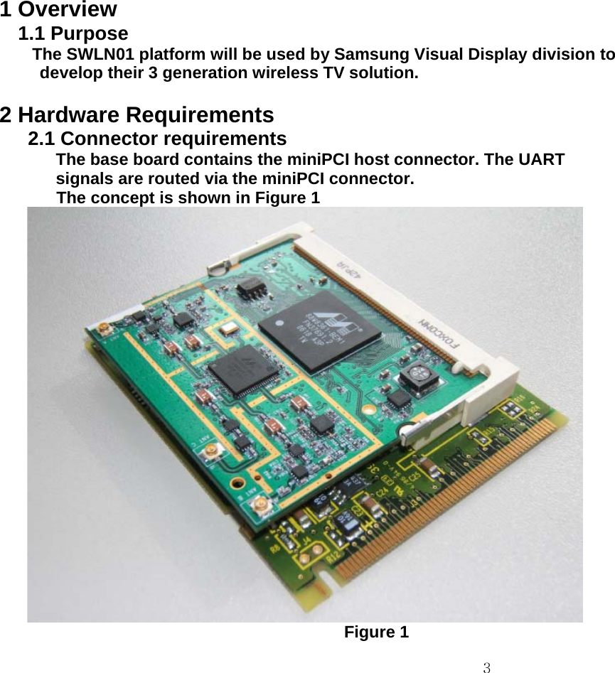
![4 2.2 Block diagram The 88W8363 has connected to it an 8MB SDRAM for data storage and if necessary some code. The 8363 device is also connected to a Flash which stores the code. 88W8363BasebandProcessorPCLK88W8060RF transceiverGPIO[0-9]TR_Q_N_AFLEX_BUS Flash1MBitMEM_BUSDDRDDRDDRSDRAM 64MbitJTAGTR_I_P_BTR_Q_P_BTR_I_N_BTR_Q_P_ATR_I_N_ATR_I_P_ATR_Q_N_BRX5ATX5ARX5BTX5BRX5CMDR753FBPF MDR753FMDR753FMDR753FMDR753FLNALX5560PA LX5530LX5560LX5530LX5560LPFDEADEASWMASW007-107MiniPCIHostinterfacePAD[31-0]PA/RF CONTROLPERRFRAMEIRDYTRDYSWMASW007-107XTAL...PCI InterfaceRX_I_P_CRX_I_N_CRX_Q_P_CRX_Q_N_CPCI_CLK_BCLK_INGPIO[10-15]GPIO12GPIO13Regulator88PG817EGPIO15GPIO1440Mhz40MhzCLK_OMEM_CLK160Mhz](https://usermanual.wiki/Samsung-Electronics-Co/SWLN01/User-Guide-841297-Page-4.png)