Samsung Electronics Co SWLN01 Wireless LAN Mini PCI Card with SM MIMO User Manual
Samsung Electronics Co Ltd Wireless LAN Mini PCI Card with SM MIMO Users Manual
Users Manual

1
SWLN01 : Wireless Module User Manual
Date: April 9, 2007
Version: 1.0
Visual Display Division
Samsung Electronics.Co.Ltd
---------------------------------------------------------------------------------------------------------------
2
SWLN01 : IEEE802.11n Wireless Module Data Sheet .............................................1
Date: April 9, 2007........................................................................................................1
Version: 1.0 ..................................................................................................................1
1 Overview.....................................................................................................................3
1.1 Purpose................................................................................................................3
2 Hardware Requirements............................................................................................3
2.1 Connector requirements ....................................................................................3
2.2 Block diagram......................................................................................................4
2.3 RF Requirements (including system performance) ........................................5
3 Software requirements .............................................................................................6
3.1 Description .........................................................................................................6
3.2 Operating mode .................................................................................................6
3.3 UART Interface ...................................................................................................6
3.4 Security ...............................................................................................................6
3.5 Channel configuration.......................................................................................7
3.6 Dynamic Channel Selection .............................................................................7
3.7 DFS Requirements ............................................................................................7
3.8 Video streaming.................................................................................................7
3.9 Quality of service...............................................................................................7
3.10 Software requirements table ..........................................................................8
3.11 Compliance Testing ........................................................................................9
3.12 Temperature Range.........................................................................................9
4. Rest Specifications …………………………………………………………………..….9
5. Manufacturing Setup ……………………………………………………………………9
…
3
1 Overview
1.1 Purpose
The SWLN01 platform will be used by Samsung Visual Display division to
develop their 3 generation wireless TV solution.
2 Hardware Requirements
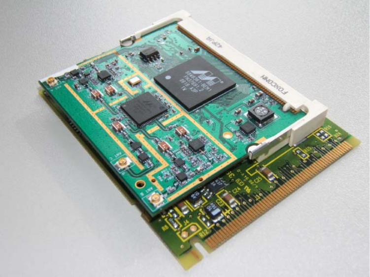
2.1 Connector requirements
The base board contains the miniPCI host connector. The UART
signals are routed via the miniPCI connector.
The concept is shown in Figure 1
Figure 1
4
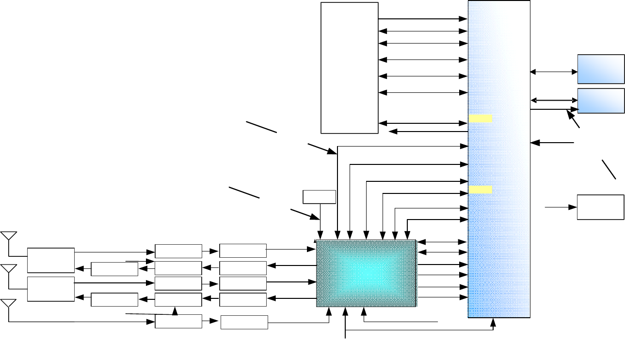
2.2 Block diagram
The 88W8363 has connected to it an 8MB SDRAM for data storage and if necessary
some code. The 8363 device is also connected to a Flash which stores the code.
88W8363
Baseband
Processor
PCLK
88W8060
RF
transceiver
GPIO[0-9]
TR_Q_N_A
FLEX_BUS Flash
1MBit
MEM_BUS
DDR
DDR
DDR
SDRAM
64Mbit
JTAG
TR_I_P_B
TR_Q_P_B
TR_I_N_B
TR_Q_P_A
TR_I_N_A
TR_I_P_A
TR_Q_N_B
RX5A
TX5A
RX5B
TX5B
RX5C
MDR753F
BPF
MDR753F
MDR753F
MDR753F
MDR753F
LNA
LX5560
PA LX5530
LX5560
LX5530
LX5560
LPF
DEA
DEA
SW
MASW007-
107
MiniPCI
Host
interface
PAD[31-0]
PA/RF
CONTROL
PERR
FRAME
IRDY
TRDY
SW
MASW007-
107
XTAL
.
.
.
PCI
Interface
RX_I_P_C
RX_I_N_C
RX_Q_P_C
RX_Q_N_C
PCI_CLK_B
CLK_IN
GPIO[10-15]
GPIO12
GPIO13
Regulator
88PG817E
GPIO15
GPIO14
40Mhz
40Mhz
CLK_O
MEM_CLK
160Mhz
5
The Baseboard mPCI host connector will be a physical mPCI connector but the logical
pins shall not be mPCI complaint.
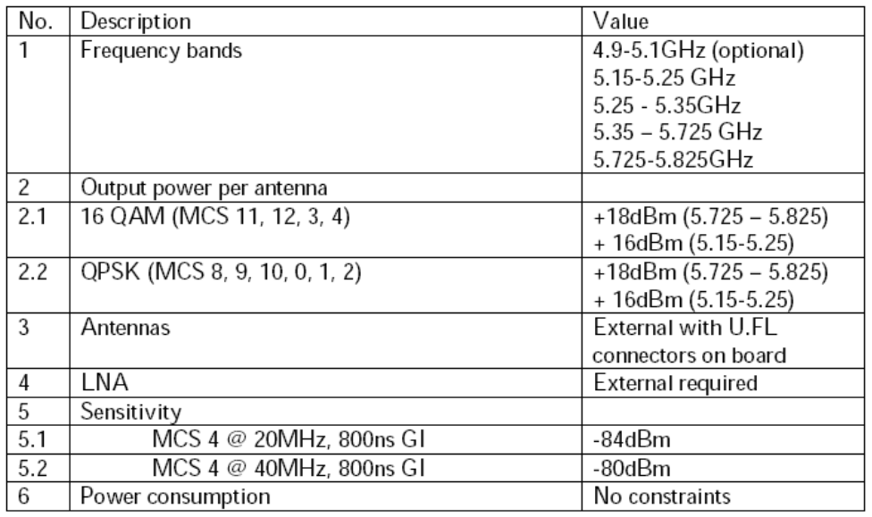
2.3 RF Requirements (including system performance)
The Card should achieve good range performance at the specified operating points (in
terms of data rate). The operating points of interest are
1. 75 Mbps MPEG TS throughput using 40MHz bandwidth
2. 50m outdoor / 75 Mbps throughput using 40MHz bandwidth
6
3 Software requirements
3.1 Description
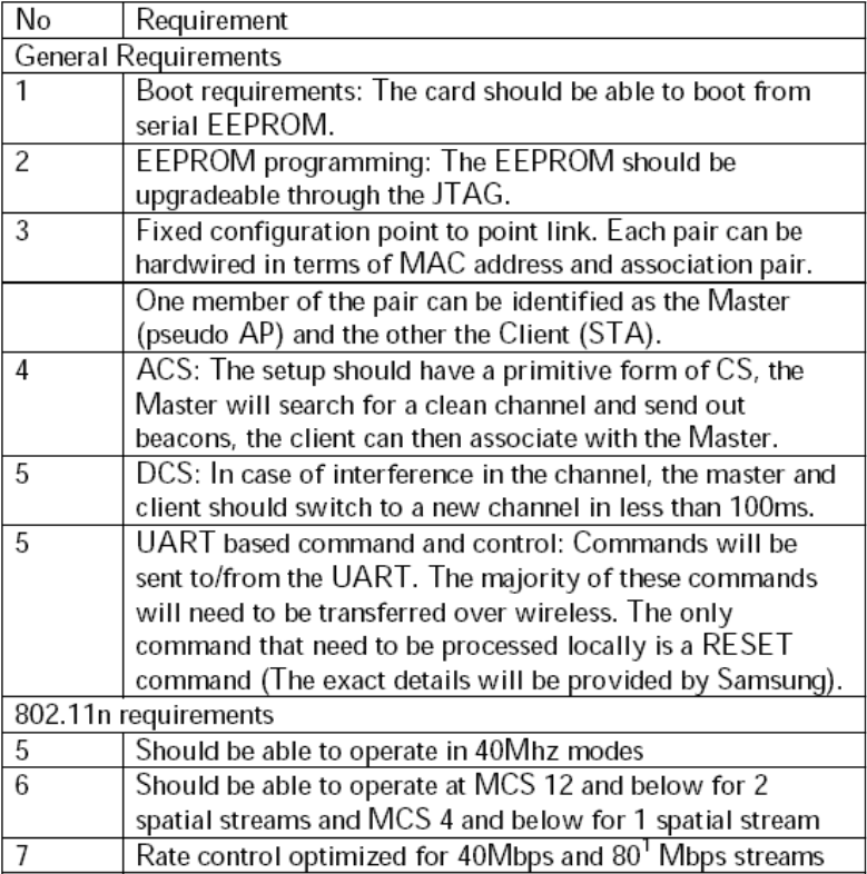
SWLN01 is a stand alone wireless client; it does not have any drivers on the host. The
card is expected to boot-up automatically and function on it own.
The only control interface is through the UART. The number of controls to the wireless
UART interface: Essentially an end-to-end control interface. The commands that
come-in to the wireless card are expected to be sent over the air to a similar card
on the other side where the commands are sent out through the UART. A very
few commands (such as initialize) are meant for the card itself.
3.2 Operating mode
A pair of cards will operate as a point-to-point link. Ad-hoc mode of operation is
adequate. It will be ideal to designate one card as master (lite AP) and the other as a
client. The master will be the one that transmits the beacon.
3.3 UART Interface
The UART Interface should support
1. 115,200 bps baud rate
2. RTS-CTS disabled
3. 8-N-1, No flow control
The packet transmission should be in Big-Endean format.
3.4 Security
SWLN01 should support AES-CCMP encryption similar to IEEE 802.11i standard. All
MPEG TS packets received over the TS interface should be encrypted with the security
key. Encrypted packets should be decrypted by the receiver.
The security keys will be negotiated between host processors. The encrypted security
keys will be passed to SWLN01 through UART commands. The encrypted security key
will be decrypted by SWLN01 using AES. Periodic re-key negotiation will be done by host
processor and keys plumbed down to SWLN01 over UART interface.
7
3.5 Channel configuration
The master should implement some form of automatic channel selection upon power up.
The cleanest channel should be chosen in order to ensure good operation.
3.6 Dynamic Channel Selection
If interference is detected, both the master and client should move to a cleaner channel.
This switch should be done with limited video quality loss. The total time from the arrival
of interference in the channel to transmission of video on a different channel should be
less than 500ms.
3.7 DFS Requirements
DFS is not required in the US when operating in the 5.15-5.25 GHz and the 5.725-5.825
GHz frequencies. The SWLN01 platform will operate only in these frequencies.
3.8 Video streaming
The master will receive the MPEG TS packets through the TS interface. These packets
are expected to aggregated, encrypted and transferred over the air to the client device. In
the client the packets are decrypted, de-aggregated and sent out through the TS interface.
The TS packets should be sent using the highest priority.
A near-isochronous link should be mimicked between the TS_IN and TS_OUT. The jitter
should be in order of few milliseconds.
The end-to-end latency from TS_IN to TS_OUT should be in order of few 10s of
milliseconds.
3.9 Quality of service
Two classes of traffic need to be transferred over this wireless link. The video class will
use the highest priority. The data on the UART should be transferred as best-effort.
8
3.10 Software requirements table
9
3.11 Compliance Testing
FCC Part 15 certification will be required for SWLN01 platform.
3.12 Temperature Range
The SWLN01 platform will operate from 0-70C.
4 . Rest Specification
Refer to 88W8060 & 88WW8363 PDF Files
Adobe Acrobat
7.0 Doc um en t
Adobe Acrobat
7.0 Doc um en t
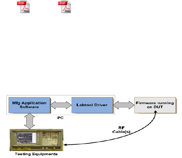
5. Manufacturing Setup
•Manufacturing (Mfg) tools provide lower level access to the basic functions of the WLAN chips
•
Mainly used for calibration and basic performance testing
•
Mfg tools are composed of a few components
–
Mfg firmware
–
Labtooldriver
–
Mfg application software
–
Testing equipments
10
6. FCC information
This device complies with part 15 of the FCC Rules. Operation is subject to the following two
conditions:
(1) This device may not cause harmful interference, and (2) this device must accept any
Interference received, including interference that may cause undesired operation.
Changes or modifications not expressly approved by the party responsible for compliance
could void the user’s authority to operate the equipment.
To comply with the FCC RF exposure compliance requirements, this device and its antenna must
not be co-located or operated in conjunction with any other antenna or transmitter.
The final device into which this transmitter module is installed must be labeled with the following
statement:
“This device contains TX FCC ID: A3LSWLN01.” If this transmitter will be configured as a pc
peripheral, it will be the OEM’s responsibility to obtain authorization as such (either through
Certification of Declaration of Conformity) prior to marketing of the device. “
Within the 5.15-5.25 GHz band, this device will be restricted to indoor operations to reduce
Any potential for harmful interference to co-channel MSS operations.
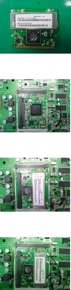
HOW TO ASSEMBLE A3LSWLN01 MODULE
1. This is A3LSWLN01 Module
2. There is Wireless Module Socket on the PDP B’d
3. A3LSWLN01 to be inserted about 45 degree.
4. After insert completely, Antenna to be connected
Warning:
In order to comply with FCC RFx requirements, the EUT
must be installed such that a minimum separation distance of
20 cm is maintained between the antennas and all persons
during normal use.