Samsung Electronics Co WBS24BASIC WLAN ACCESS POINT User Manual
Samsung Electronics Co Ltd WLAN ACCESS POINT
UserManual.wiki
>
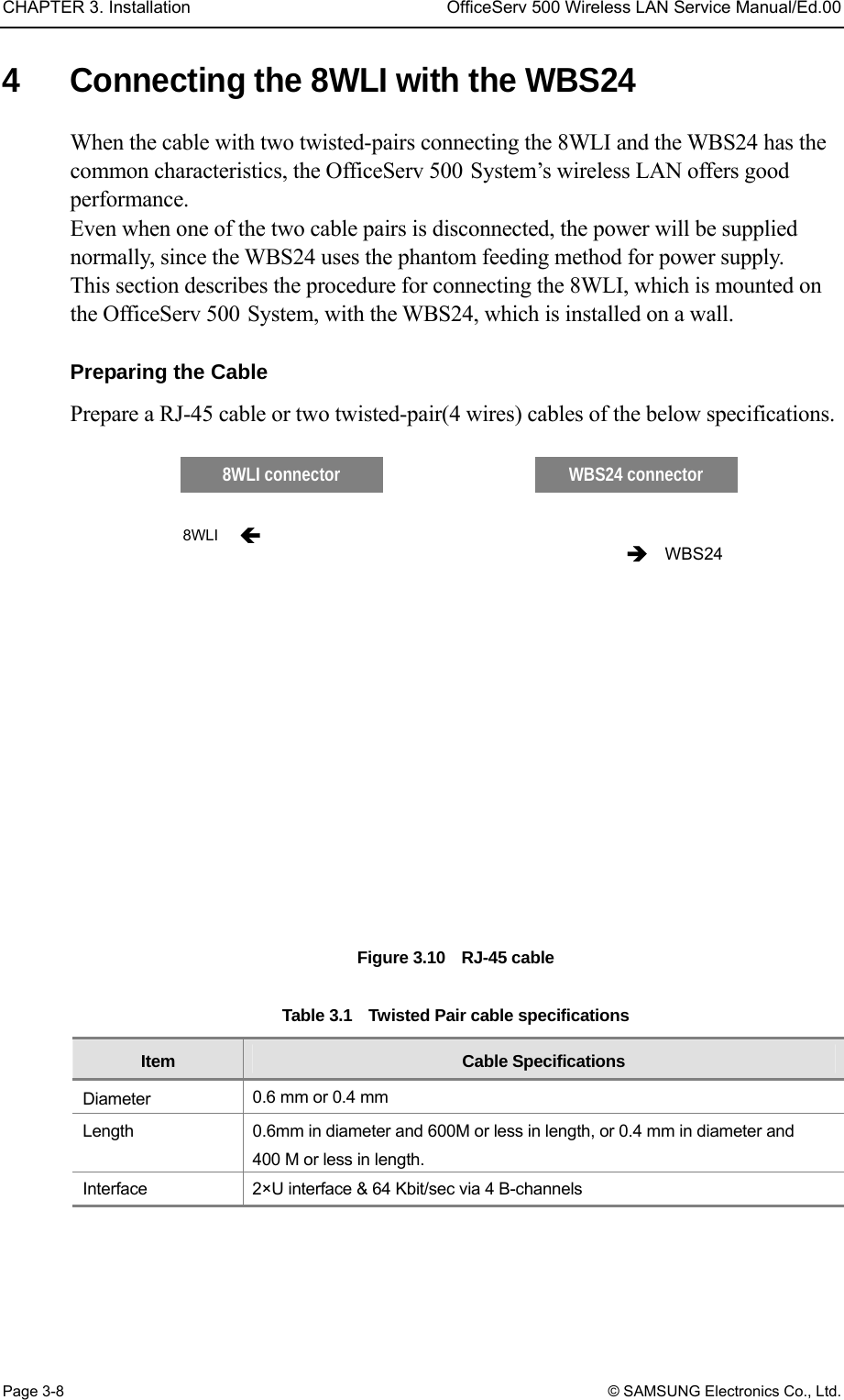
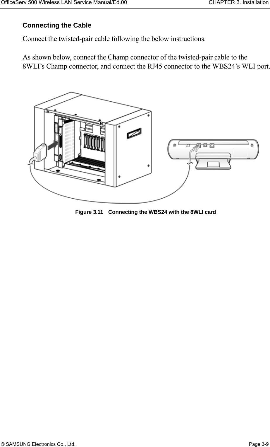
Samsung Electronics Co
>
WBS24BASIC User Manual
USERS MANUAL
Navigation menu
Upload a User Manual
Namespaces
Wiki Guide
HTML
PDF
Info
Views
User Manual
Discussion / Help
Navigation

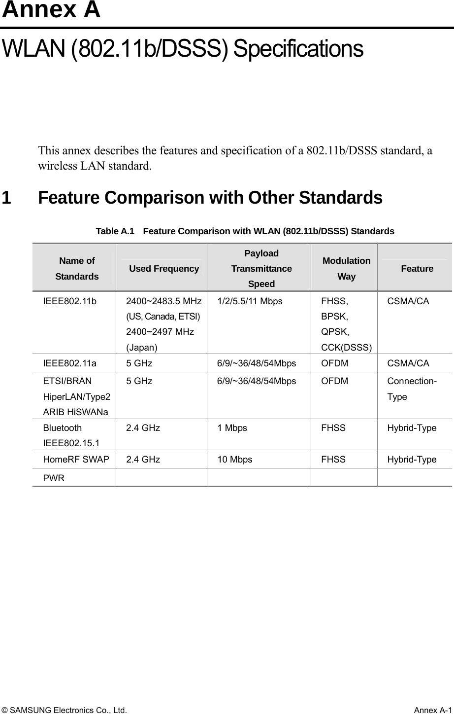
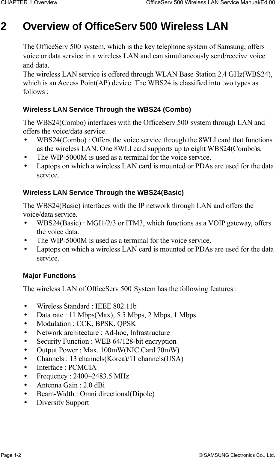
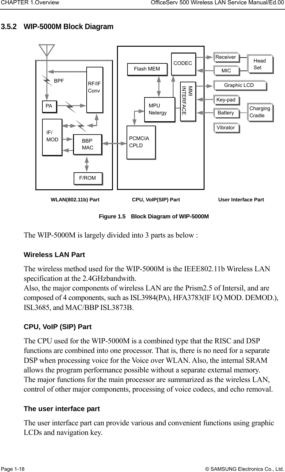
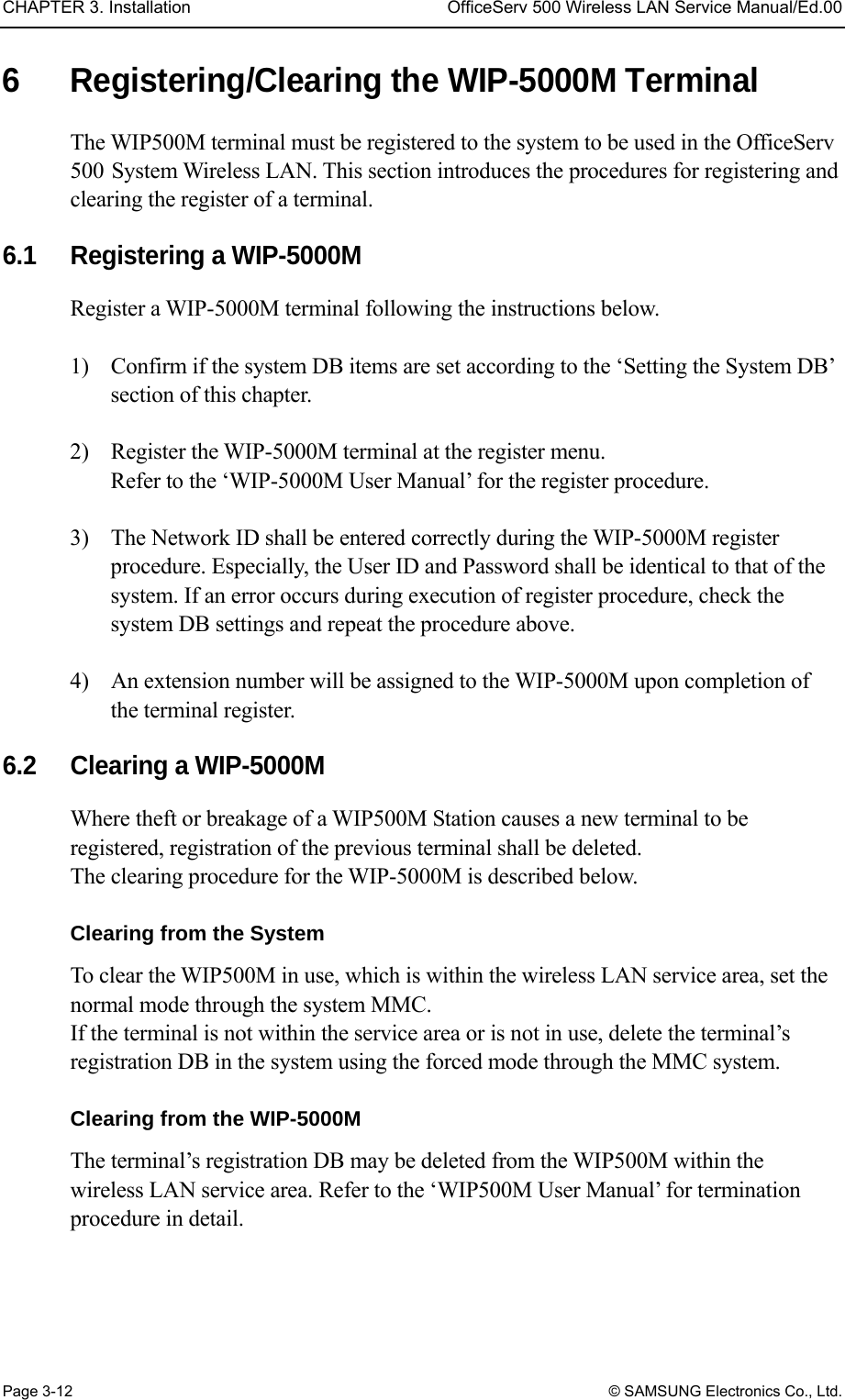
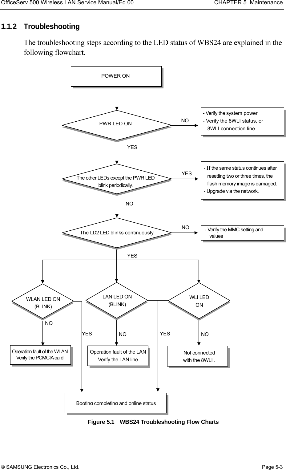
![Table of Contents OfficeServ 500 Wireless LAN Service Manual/Ed.00 Page XII © SAMSUNG Electronics Co., Ltd. LIST OF FIGURES UFigure 1.1 Configuration Diagram of U OfficeServ 500 U Wireless LANU............................ 1-4 UFigure 1.2 8WLI Block DiagramU..................................................................................... 1-8 UFigure 1.3 Block Diagram of WBS24 WBS24 (Combo)U............................................... 1-14 UFigure 1.4 Block Diagram of WBS24 WBS24 (Basic)U.................................................. 1-17 UFigure 1.5 Block Diagram of WIP-5000MU..................................................................... 1-18 UFigure 2.1 Front side of 8WLI CardU................................................................................ 2-1 UFigure 2.2 Front side of WBS24 (Combo)U...................................................................... 2-2 UFigure 2.3 Back side of WBS24 (Combo)U...................................................................... 2-4 UFigure 2.4 Front side of WBS24 (Basic)U......................................................................... 2-5 UFigure 2.5 Back side of WBS24 (Basic)U......................................................................... 2-6 UFigure 3.1 The Wireless LAN Installation ProcedureU..................................................... 3-1 UFigure 3.2 Mounting the 8WLI Card (1)U.......................................................................... 3-2 UFigure 3.3 Mounting the 8WLI Card (2)U.......................................................................... 3-3 UFigure 3.4 Mounting the WBS24 on a Concrete Wall-Drilling a HoleU............................. 3-5 UFigure 3.5 Mounting the WBS24 on a Concrete Wall-Inserting the Plastic AnchorU....... 3-5 UFigure 3.6 Mounting the WBS24 on a Concrete Wall-Tightening the ScrewU................. 3-5 UFigure 3.7 Mounting the WBS24 on a Concrete WallU.................................................... 3-6 UFigure 3.8 Mounting the WBS24 on a concrete wall-Attach the WBS24 to its PropU...... 3-6 UFigure 3.9 Installing a Desk WBS24U.............................................................................. 3-7 UFigure 3.10 RJ-45 cableU................................................................................................... 3-8 UFigure 3.11 Connecting the WBS24 with the 8WLI cardU.................................................. 3-9 UFigure 3.12 The Cell Boundary of WBS24U..................................................................... 3-13 UFigure 3.13 Single Cell ConfigurationU............................................................................ 3-14 UFigure 3.14 Multiple Cell ConfigurationU.......................................................................... 3-14 UFigure 3.15 Data transmission rate on Station locationU................................................. 3-15 UFigure 5.1 WBS24 Troubleshooting Flow ChartsU........................................................... 5-3 UFigure 5.2 Web screen for inquiring the WBS24 status (Initial screen)U......................... 5-4 UFigure 5.3 Web screen for inquiring the WBS24 status (Config & Status)U..................... 5-5 UFigure 5.4 Web screen for inquiring the WBS24 status (Screen for entering password)U..................................................................... 5-6 UFigure 5.5 Web screen for inquiring the WBS24 status (Restart)U.................................. 5-7 UFigure 5.6 Web screen for inquiring the WBS24 status (Wireless LAN statistics)U......... 5-8 UFigure 5.7 Web screen for Inquiring the WBS24 Status (Ethernet statistics)U................. 5-9 UFigure 5.8 Web screen for upgrading the WBS24 S/W (Initial screen)U........................ 5-11 UFigure 5.9 Web screen for upgrading the WBS24 S/W (Screen to enter a password)U...................................................................... 5-11 UFigure 5.10 Web screen for inquiring the WBS24 S/W (Firmware upgrade)U................. 5-12 UFigure 5.11 Web screen for inquiring the WBS24 S/W (Click the [Upgrade] button)U..... 5-13 UFigure 5.12 Web screen for inquiring the WBS24 S/W (In the process of upgrade)U..... 5-13](https://usermanual.wiki/Samsung-Electronics-Co/WBS24BASIC/User-Guide-384179-Page-14.png)
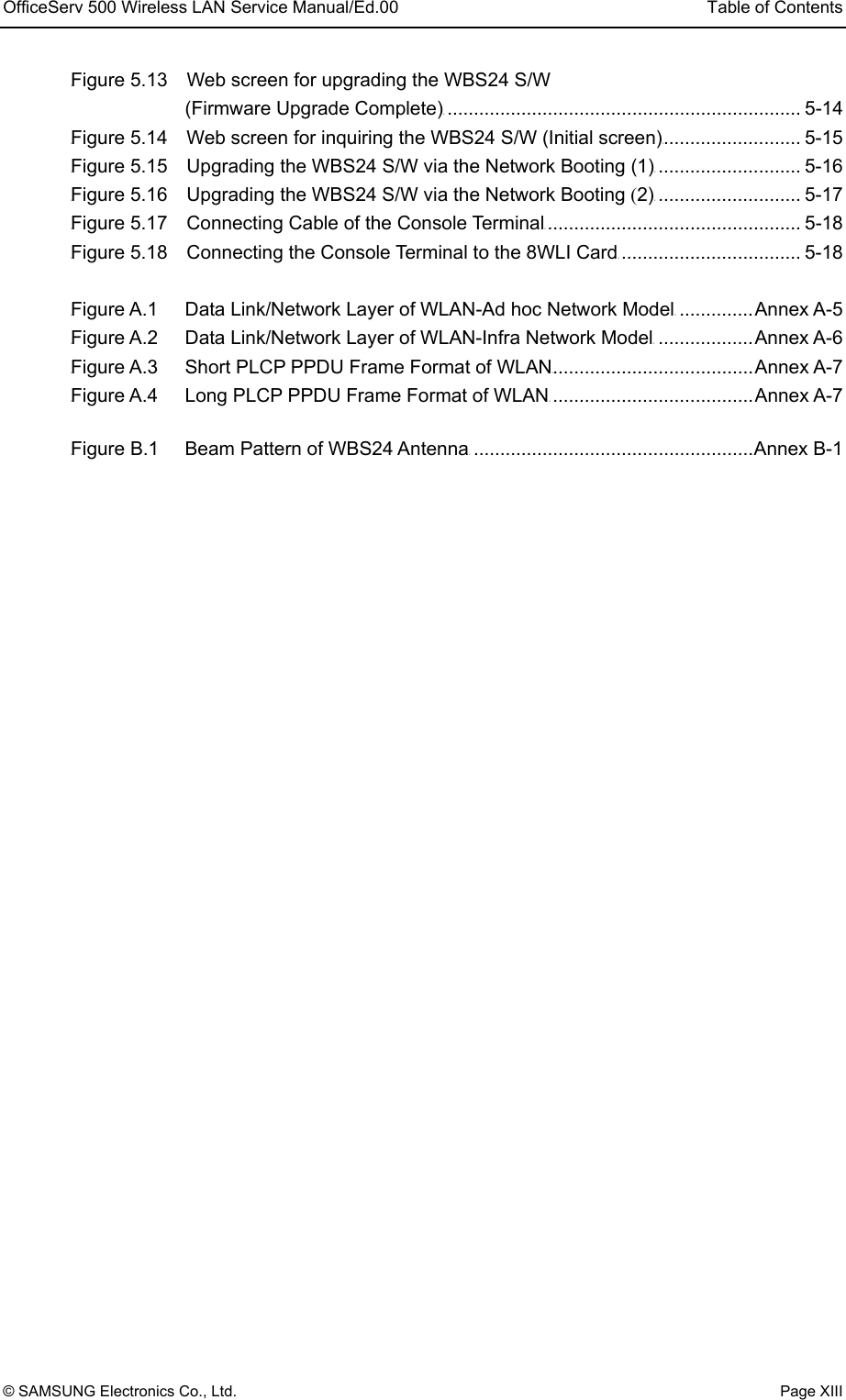
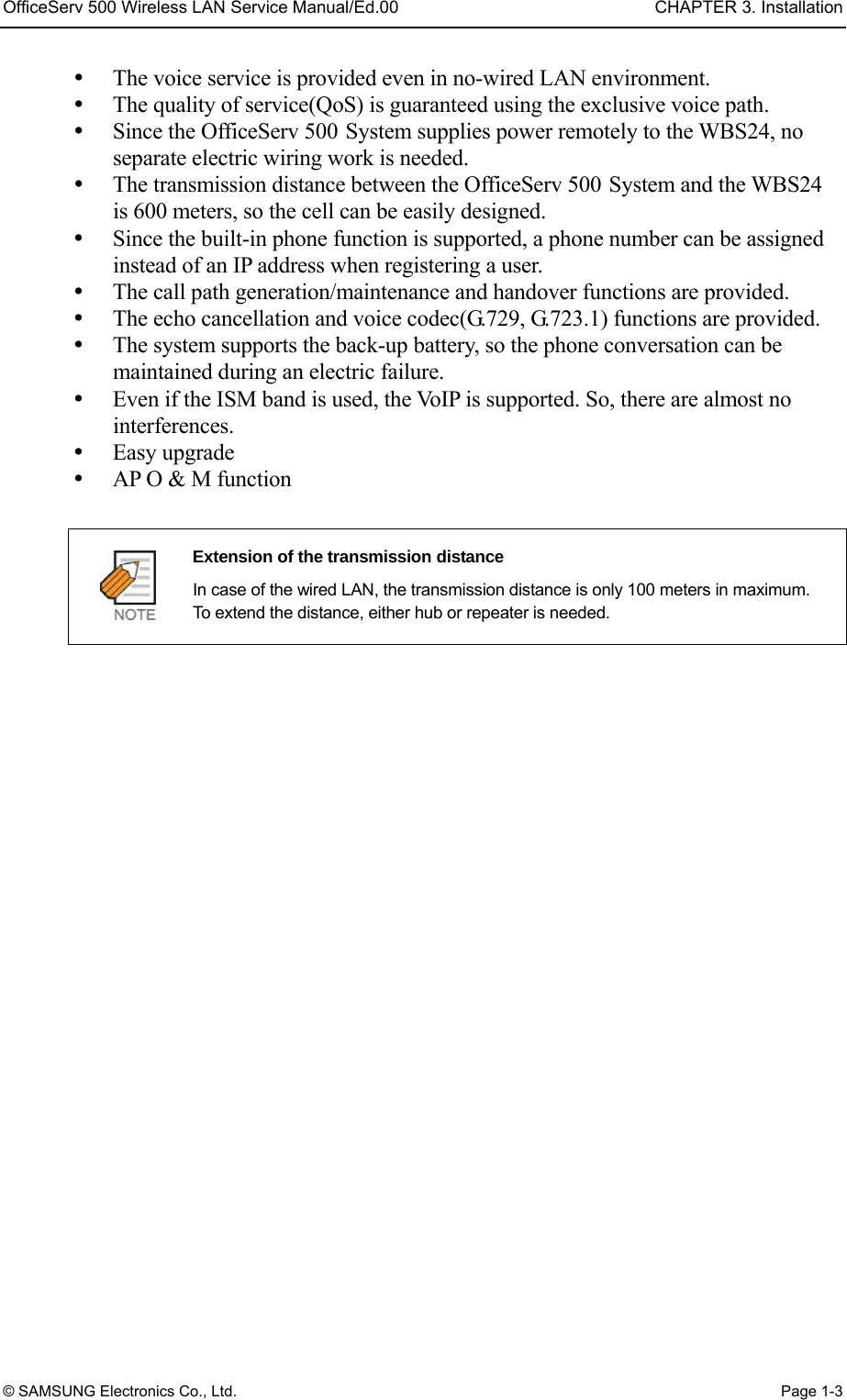
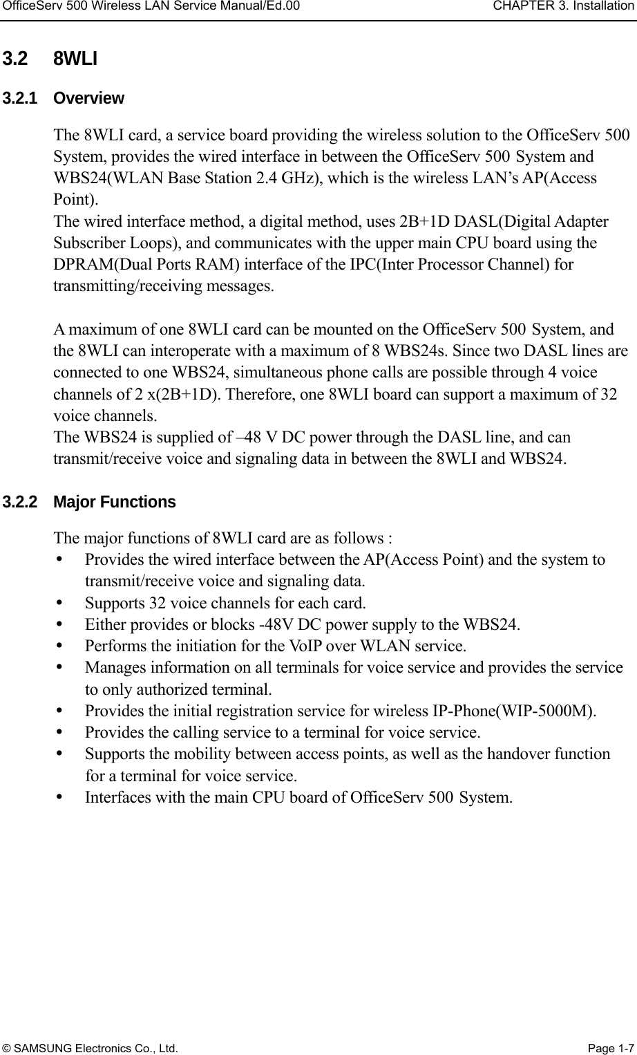
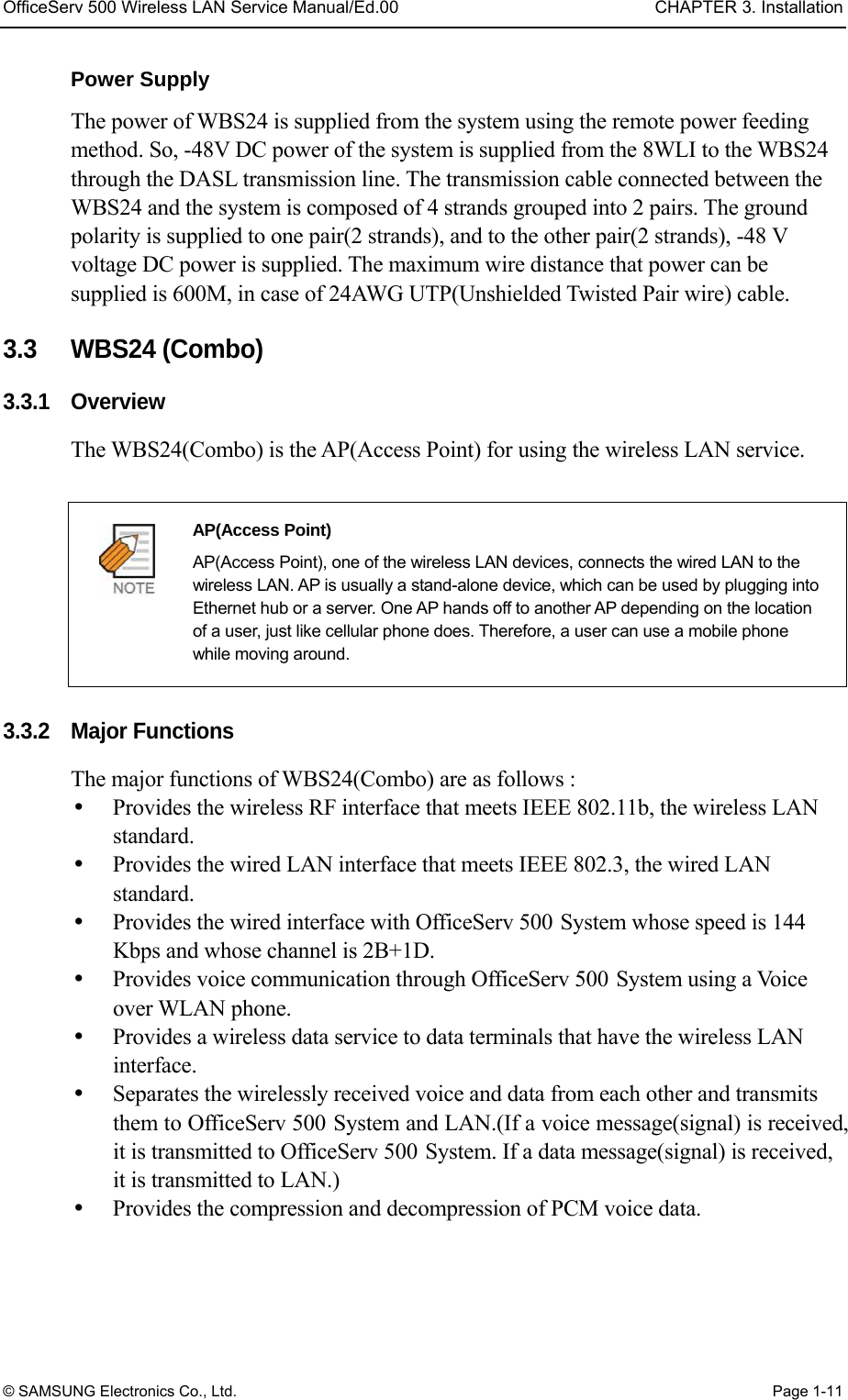
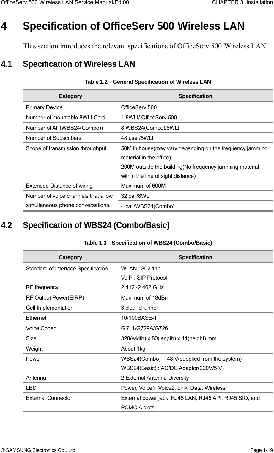
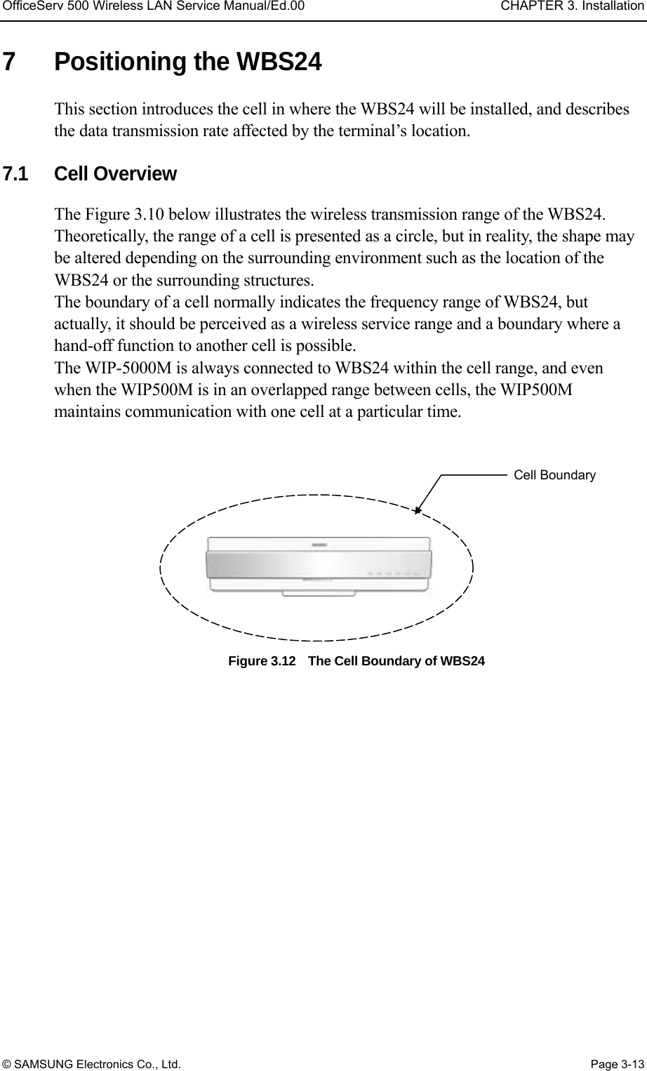
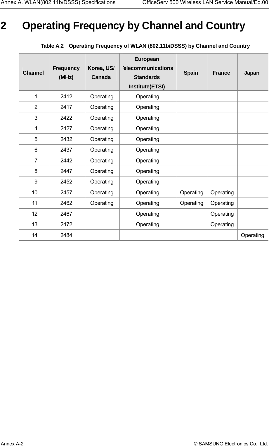
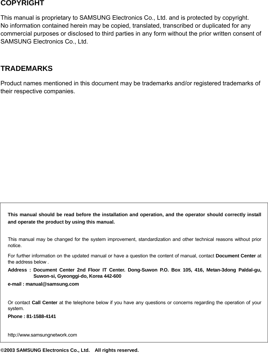
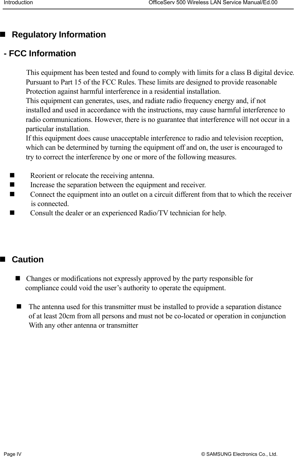
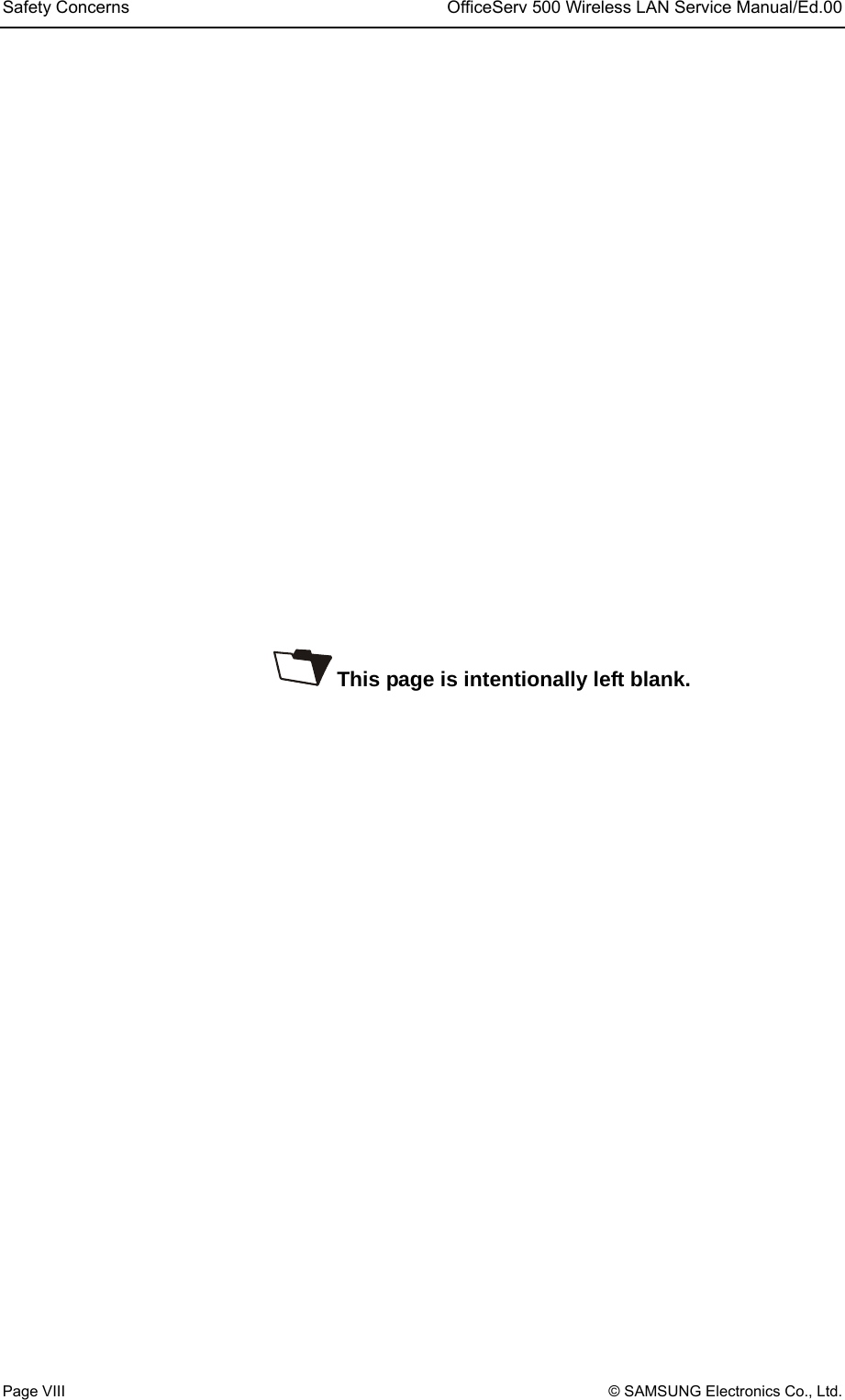
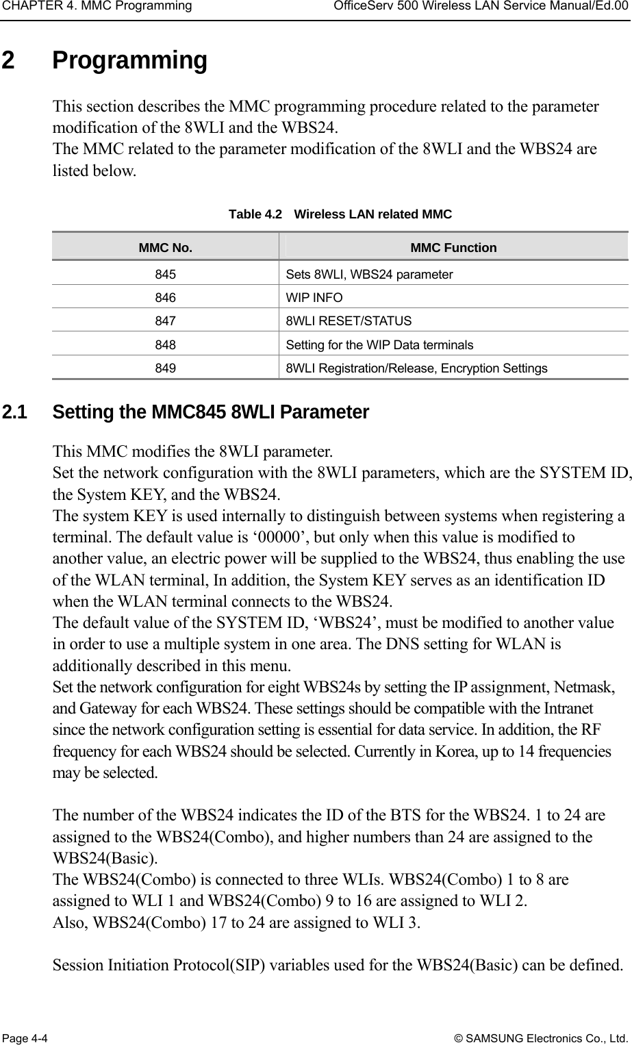
![CHAPTER 4. MMC Programming OfficeServ 500 Wireless LAN Service Manual/Ed.00 Page 4-2 © SAMSUNG Electronics Co., Ltd. 1.2 Programming Button The functions of the phone buttons for MMC programming are listed below. Table 4.1 Program buttons Button Function ▲ ▼(Up & Down) Change screen Dial key Confirm status Soft key Move cursor Keypad Select item SPK key Save data and proceed to next menu HOLD key Delete previous input TRSF key Enter program 1.3 Cautions when Programming Programming shall be done in an idle mode where the handset is on top of the telephone set. Programming may be done on any extension of a digital phone. Programming may not be done on a common single line telephone. For digital phones not equipped with the LCD screen, use the dial key to enter the numbers in the Description instead of the [▲volume▼] button. But since there are no Soft buttons, programming is limited. Therefore, with phones without the LCD screen, program only the Subscriber programs. When ‘INVALID DATA’ appears on the LCD screen, re-enter the correct data. When no key is pressed for an amount of time(key program end time, default is 60 seconds), programming will end and return to idle mode. When the handset is lifted during programming, programming will end and return to idle mode. When programming returns to idle mode by pressing the [SPK] key or the [TRSF] key, or by lifting the handset, without confirming the modified data(pressing the ‘left’ or ‘right’ key of the ‘Soft’ button), or when the phone plug is disconnected, the data entered until then and the data on the LCD screen will automatically be saved as the new data.](https://usermanual.wiki/Samsung-Electronics-Co/WBS24BASIC/User-Guide-384179-Page-60.png)
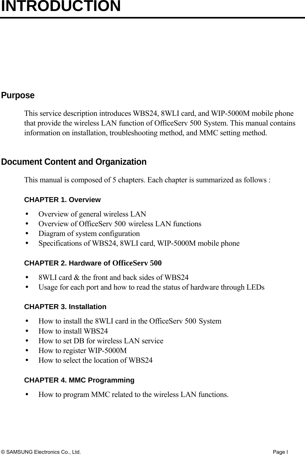
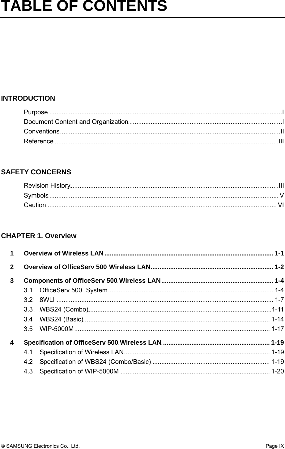
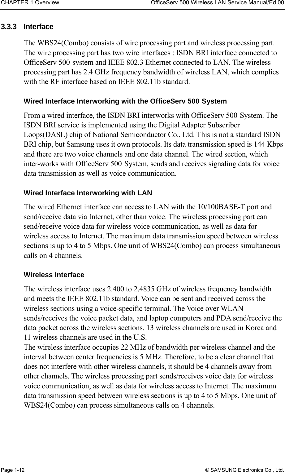
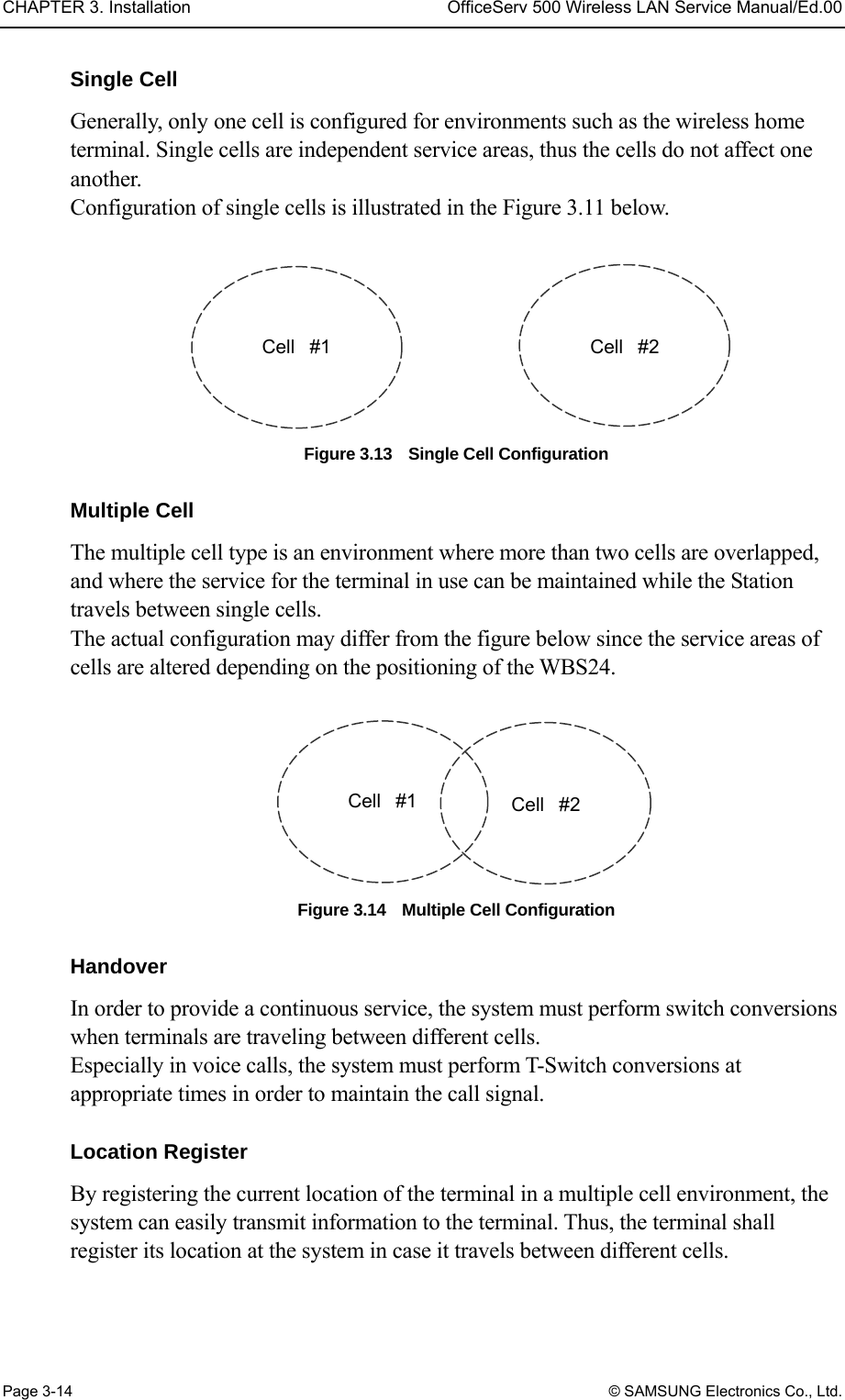
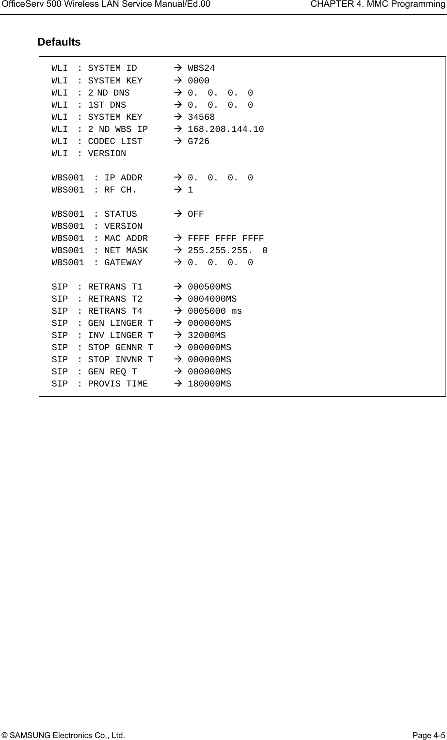
![OfficeServ 500 Wireless LAN Service Manual/Ed.00 CHAPTER 4. MMC Programming © SAMSUNG Electronics Co., Ltd. Page 4-3 1.4 Programming Procedure This section describes the overall programming procedure. The procedure shall be read carefully and thoroughly understood. The programming procedure is described as follows. Program Procedure Display Screen 1) Press the [TRSF] button, and enter 800. 2) Enter the PASSCODE (Operator or Engineer password). 3) To enter the MMC, press the dial button [1] or select the ‘ENABLE’ status by pressing the [UP & DOWN] button. 4) Enter the program number. Or, select the program number using the [UP & DOWN] button, and press [SPK]. Or, in an idle mode, press the [TRSF] button and enter the program number. 5) Proceed programming of the selected program. PROGRAMMING MODE ENTER PGM ID: ENABLE TECH PROG PASSCODE:**** ENABLE TECH PROG DISABLE TENANT:1](https://usermanual.wiki/Samsung-Electronics-Co/WBS24BASIC/User-Guide-384179-Page-61.png)
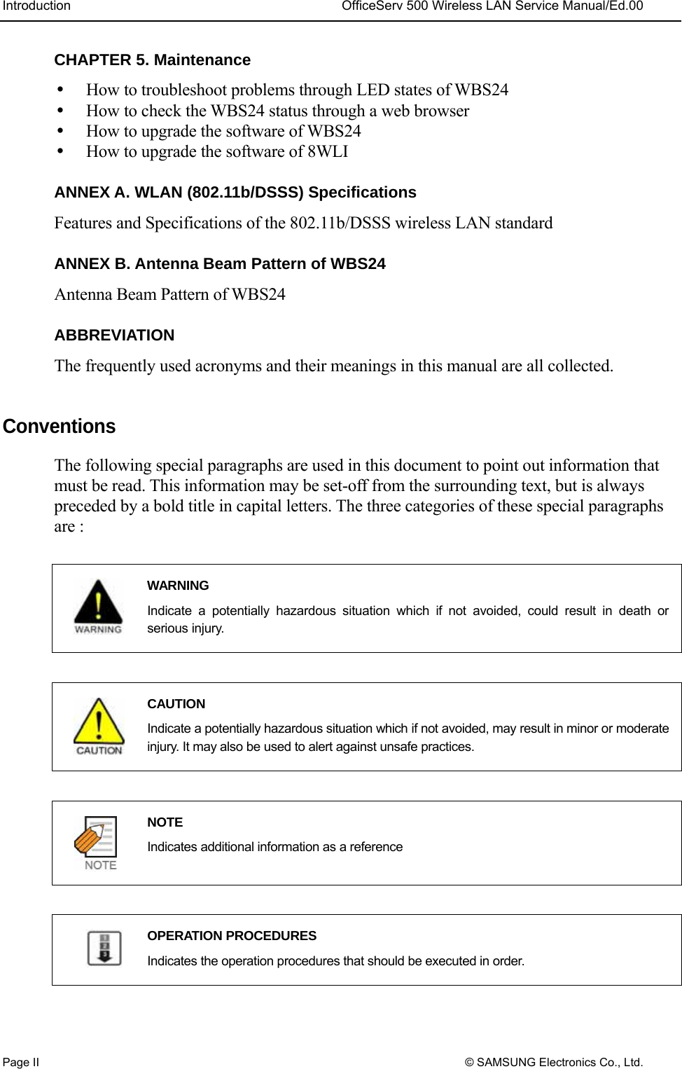
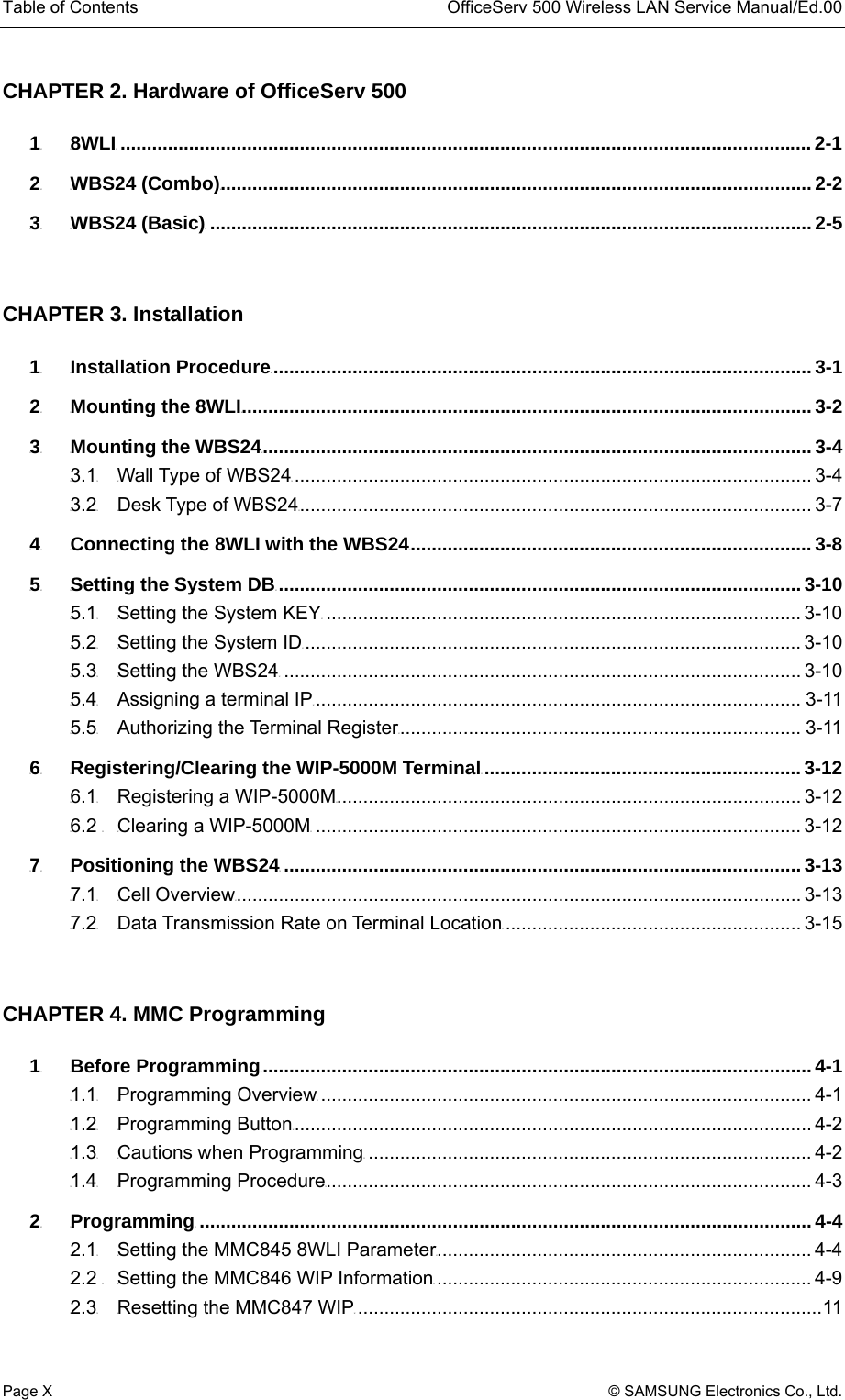
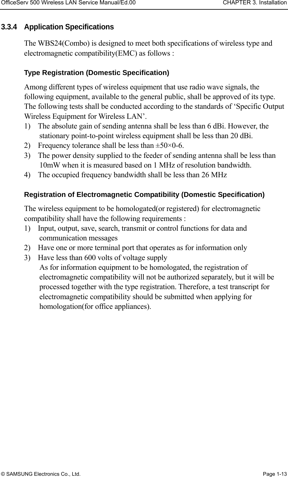
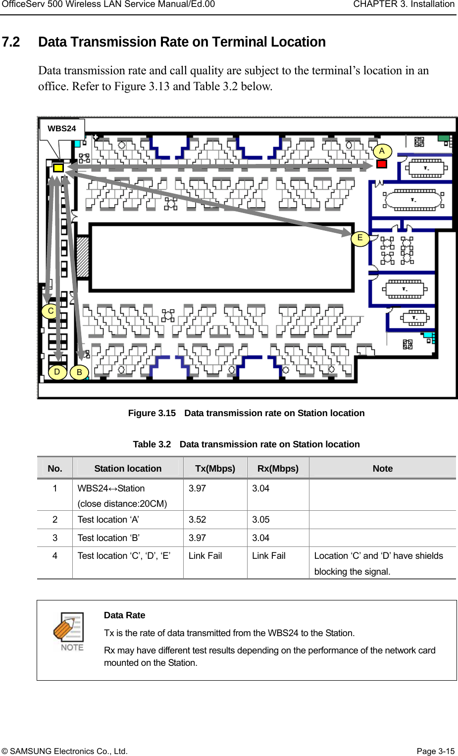
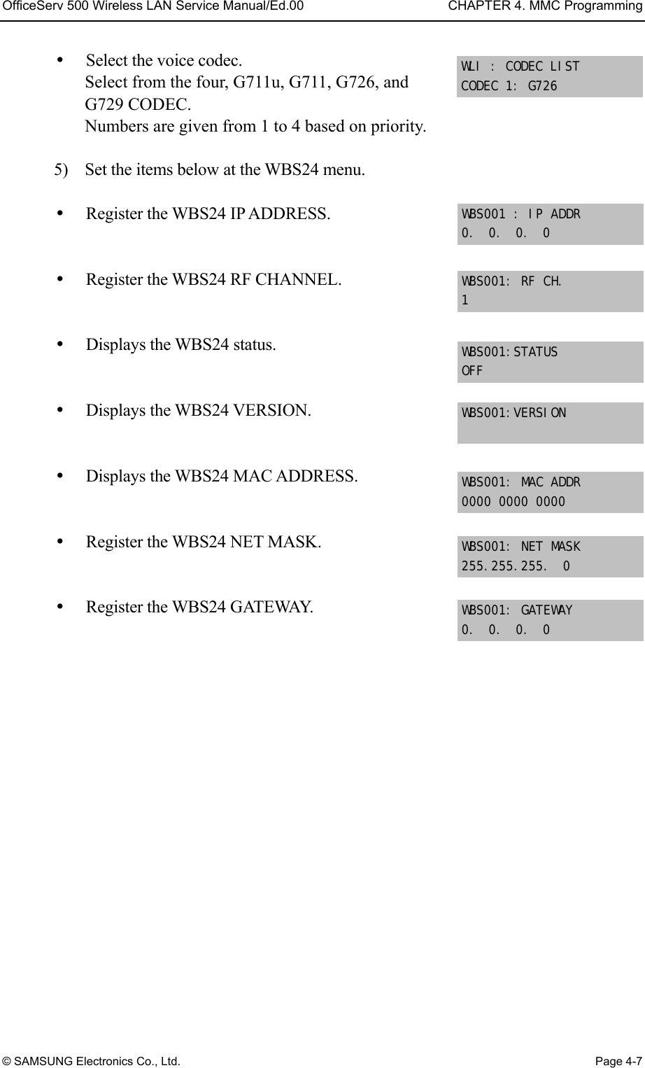
![CHAPTER 4. MMC Programming OfficeServ 500 Wireless LAN Service Manual/Ed.00 Page 4-6 © SAMSUNG Electronics Co., Ltd. Program procedure Display Screen 1) Press the [TRSF] button, and enter 845. 2) Press the [SPK] key to enter the select menu. When the cursor is at WLI, press the [UP & DOWN] button and select WLI or WBS1~254. 3) Press the Soft key and move to the SYSTEM ID. When the cursor is below SYSTEM ID, press the [UP & DOWN] key and select the setting menu for WLI or WBS24. 4) Set the items below at the WLI menu. SYSTEM ID : Use the Soft key to move the cursor. Enter the new WLI SYSTEM ID to register. Press the Soft key and proceed to next register status. Register the DNS server(second) IP. Register the DNS server(first) IP. Register the SYSTEM KEY. Register the WBS24 second IP. This is shared between all eight WBS24s. Caution when setting the WBS24 SECOND IP To use the Internet network, the first three digits of the IP assigned to the WBS24 and the first three digits of the SECOND WBS IP of the WBS24 must be identical. If the IP assigned to the WBS24 and the Station is 168.219.149.xxx, then the SECOND WBS IP of the WBS24 shall be 168.xxx.xxx.xxx. 845: WLI PARA SELECT PROG ID UWULI : SYSTEM ID WBS24 UWUBS1: IP ADDRESS 0. 0. 0. 0 WLI : SYSTEM ID WBS24 WLI : SYSTEM ID 0000 UWULI : SYSTEM ID WBS24 WLI : 2P PND DNS IP 0. 0. 0. 0 WLI : 1 ST DNS IP 0. 0. 0. 0 WLI : SYSTEM KEY 00000](https://usermanual.wiki/Samsung-Electronics-Co/WBS24BASIC/User-Guide-384179-Page-64.png)
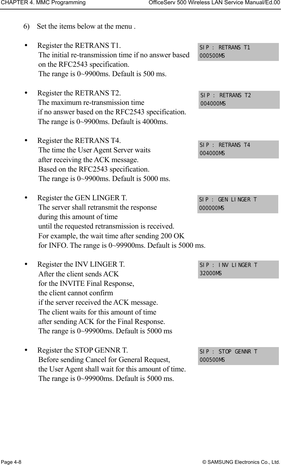
![OfficeServ 500 Wireless LAN Service Manual/Ed.00 CHAPTER 4. MMC Programming © SAMSUNG Electronics Co., Ltd. Page 4-9 Register the STOP INVNR T. Before sending Cancel for the Invite Request, the User Agent shall wait for this amount of time. The range is 0~99900 ms. Default is 5000 ms. Register the GEN REQ T. After sending General Request, he User Agent shall wait for the Final Response for this amount of time. The range is 0~99900ms. Default is 5000 ms. Register the PROVIS TIME. After receiving the Provision Response, the User Agent shall wait for this amount of time until Timeout ends. The range is 0~999900ms. Default is 180000ms Related Programs MMC 846 WIP INFO(Station information) MMC 847 WLI RESET (WLI/WBS24 status information and initialization.) MMC 848 WLI IP LIST(Station IP register) 2.2 Setting the MMC846 WIP Information This MMC sets up the WIP-5000M wireless terminal’s information. Defaults [8601] REGIETERED NO [8601] PASSWORD 0000 [8601] USER ID 1212 [8601] MAC ADDR [8601] IP ADDRESS [8601] IP OFFSET [8601] WBS NUMBER [8601] WLI NUMBER [8601] PHONE TYPE [8601] LOCATED NO SIP : GEN REQ T 000000MS SIP : PROVIS TIME 180000MS SIP : STOP INVNR T 000000MS](https://usermanual.wiki/Samsung-Electronics-Co/WBS24BASIC/User-Guide-384179-Page-67.png)
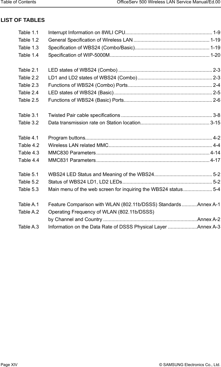
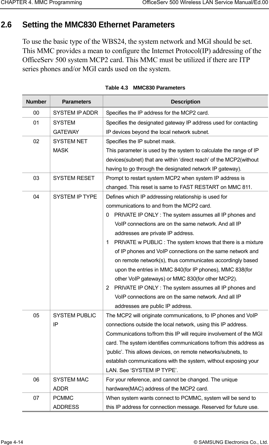
![CHAPTER 4. MMC Programming OfficeServ 500 Wireless LAN Service Manual/Ed.00 Page 4-10 © SAMSUNG Electronics Co., Ltd. Program Procedure Display Screen 1) Press the [TRSF] button, and enter 846. 2) Press the [SPK] key to enter the select menu. When the cursor is at the phone number, press the [UP & DOWN] button and select the current phonenumber information. Press the Soft key and move to the information menu of each information menu, and select the setting menu. 3) Confirm the status of terminal register for each phone number. 4) Register the PASSWORD of terminal. 5) Register the USER ID of terminal. 6) Displays the MAC ADDRESS of the registered terminal. 7) Displays the IP ADDRESS of the registered terminal. 8) Displays the IP OFFSET of the registered terminal. 9) Displays the WBS NUMBER of the registered terminal. 10) Displays the WLI NUMBER of the registered terminal. 11) Displays the PHONE TYPE of the registered terminal. 12) Displays the location of the registered terminal. 846: WIP INFO SELECT PROG ID [8601] REGIETERED NO [8601] REGIETERED NO [8601] PASSWORD 0000 [8601] MAC ADDR [8601] USER ID 1212 [8601] IP ADDRESS [8601] IP OFFSET [8601] WBS NUMBER [8601] WLI NUMBER [8601] PHONE TYPE [8601] LOCATED NO](https://usermanual.wiki/Samsung-Electronics-Co/WBS24BASIC/User-Guide-384179-Page-68.png)
![OfficeServ 500 Wireless LAN Service Manual/Ed.00 CHAPTER 4. MMC Programming © SAMSUNG Electronics Co., Ltd. Page 4-11 Related Programs MMC 847 WLI RESET MMC 848 WLI IP LIST MMC 849 WLI REGIST 2.3 Resetting the MMC847 WIP This MMC is used for rebooting the 8WLI or the WBS24, by software or independently. This MMC is also used for initializing the WBS24 or verifying the current connection status of the WBS24. Program Procedure Display Screen 1) Press the [TRSF] button, and enter 847. 2) Press the [SPK] key and enter the select menu. Press the Soft key and confirm initialization of WLI. 3) Press the Soft key, or press [1] to select YES, and the WLI will be initialized. 4) Press the Soft key, or press [1] to select YES, and the WBS24 will be initialized. 5) Displays current connection status of the WBS24. Related Programs MMC 846 WIP INFO MMC 848 WLI IP LIST MMC 849 WLI REGIST 2.4 Setting the MMC848 WIP Lists This MMC848 is used when viewing the IP list assigned to 8WLI, or when creating a new IP list. Up to 100 IP lists may be entered. MMC848 command is used for setting the MAC address of data terminals to use wireless LAN. 847: WLI RESET SELECT PROG ID RESTART WLI : 1 RESET NOW ? NO RESTART WBS : 001 RESET NOW ? NO WBS STATUS : 001 N N N N N N N N](https://usermanual.wiki/Samsung-Electronics-Co/WBS24BASIC/User-Guide-384179-Page-69.png)
![CHAPTER 4. MMC Programming OfficeServ 500 Wireless LAN Service Manual/Ed.00 Page 4-12 © SAMSUNG Electronics Co., Ltd. Program Procedure Display Screen 1) Press the [TRSF] button, and enter 848.. 2) Press the [SPK] key and enter the select menu. Press the Soft key to change the IP ADDRESS while assigning the IP ADDRESS. 3) Use the Soft key to position the cursor at an IP ADDRESS, and assign the IP ADDRESS by entering values of 0~255. 4) Numbers next to USED indicates the terminal number from which the IP ADDRESS was assigned. Related Programs MMC 846 WIP INFO MMC 847 WLI RESET MMC 849 WLI REGIST 2.5 Setting the MMC849 WLI REGIST This MMC is used to enable or disable the register of a WIP500M mobile phone within the WLAN. This MMC is also used to approve the WEP(Wired Equivalent Privacy) enabling function where the WLAN is encrypted. The WEP key, which must be used when WEP is enabled, can be configured with 16 characters or less. Also, the MMC is used to set MAC addresses in the data terminal in order to use the wireless LAN. IP:001 USED 0.0.0.0 848: WLI LISTS SELECT PROG ID IP:001 USED 168.0.0.0 IP:001 USED 8601 168.219.149.5](https://usermanual.wiki/Samsung-Electronics-Co/WBS24BASIC/User-Guide-384179-Page-70.png)
![OfficeServ 500 Wireless LAN Service Manual/Ed.00 CHAPTER 4. MMC Programming © SAMSUNG Electronics Co., Ltd. Page 4-13 Program Procedure Display Screen 1) Press the [TRSF] button, and press 849. 2) Press the [SPK] key to enter the select menu. Enter the PASSCODE to activate the register. 3) Select ENABLE to register the terminal to the REGISTER WLI. 4) Select the WEP KEY setting when ENCRYPTION is selected. 5) Enter WEP KEY values when the WEP KEY is set. 6) Can clear the register status for each terminal also. 7) Press the soft key in the IP to change or allocate a MAC address. Related Programs MMC 846 WIP INFO MMC 847 WLI RESET MMC 848 WLI IP LIST ENTER PASSCODE **** 849: WLI REGIST SELECT PROG ID WLI REGISTRATION ENABLE WBS WEP SERVICE DISABLE WEP KEY WIP REGIST CLEAR 8601:FORCED MAC LIST : 01 FFFFFFFFFFFF](https://usermanual.wiki/Samsung-Electronics-Co/WBS24BASIC/User-Guide-384179-Page-71.png)
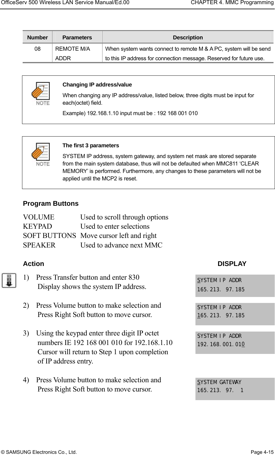
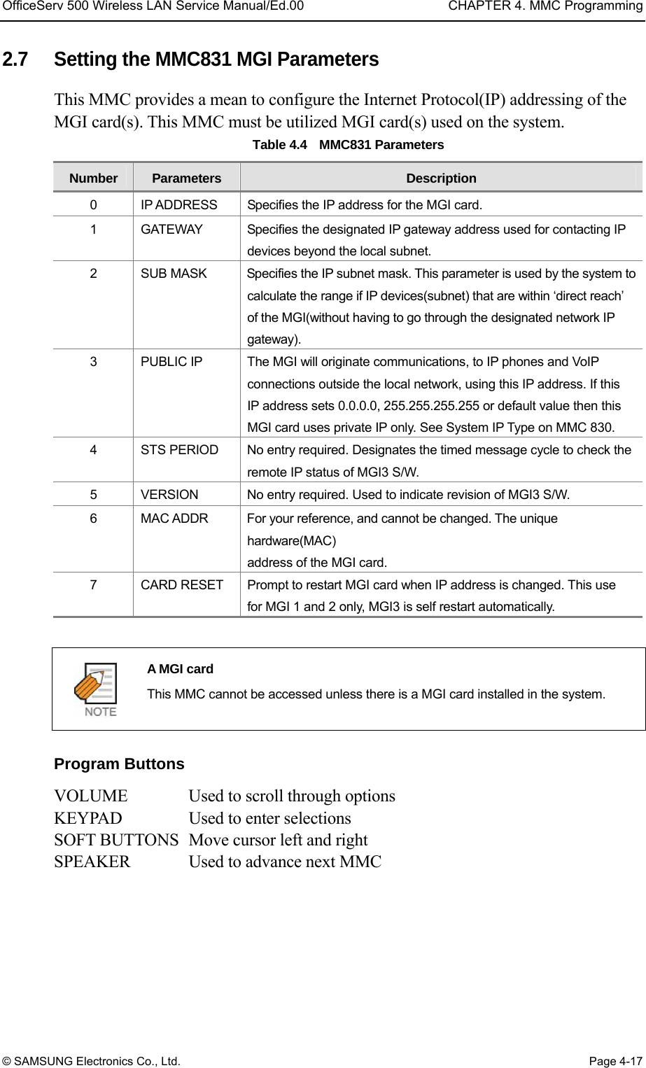
![CHAPTER 4. MMC Programming OfficeServ 500 Wireless LAN Service Manual/Ed.00 Page 4-18 © SAMSUNG Electronics Co., Ltd. Action DISPLAY 1) Press Transfer button and enter 831 Display shows the first MGI card 2) Enter MGI number OR Press Volume button to make selection and press Right Soft button to move cursor Press Volume button to make selection and press Right Soft button to move cursor. 3) Enter MGI parameter number OR Press Volume button to make selection and press Right Soft button to move cursor. Press Volume button to make selection and press Right Soft button to move cursor. 4) Enter MGI parameter OR Press Right Soft button to move cursor. Press Right Soft button to move cursor. 5) Press Transfer button and enter to exit OR Press Speaker button to advance next MMC. Default Data IP ADDRESS : 1.1.1.1 GATEWAY : 1.1.1.1 SUB MASK : 255.255.255.0 PUBLIC IP : 1.1.1.1 STS PERIOD : 00 SEC VERSION : V4 CARD RESET : NO Related Items MMC 615 MGI GROUP MMC 830 ETHERNET PARAMETERS MMC 838 PRIVATE IP ADDRESSES MMC 840 IP SET INFOMATION MMC 841 SYSTEM IP OPTIONS [U3U801] IP ADDRESS 168.219. 76.101 [3801] UIUP ADDRESS 168.219. 76.101 [3801] IP ADDRESS U1U68.219. 76.101 [3801] UIUP ADDRESS 165. 10. 1.100](https://usermanual.wiki/Samsung-Electronics-Co/WBS24BASIC/User-Guide-384179-Page-76.png)
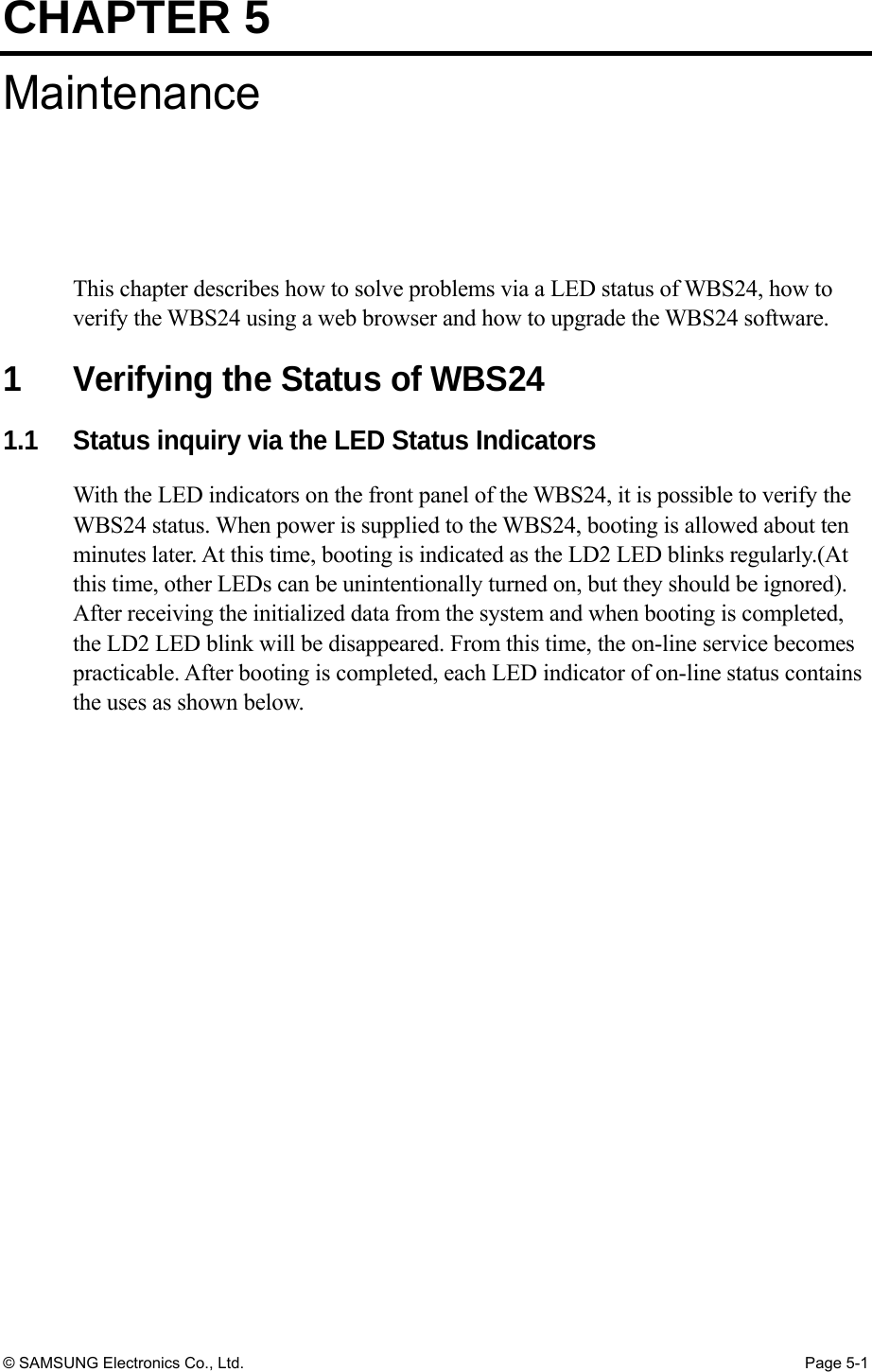
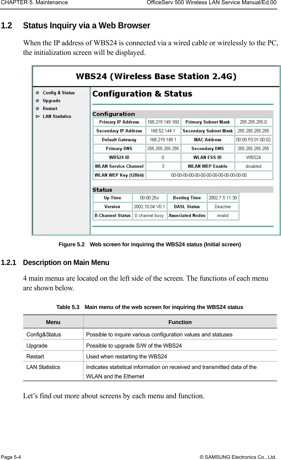
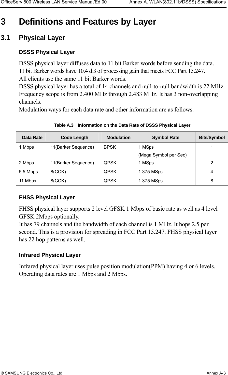
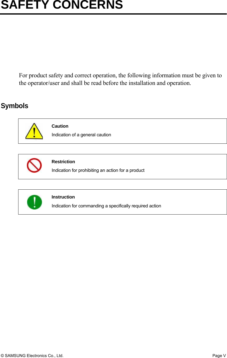
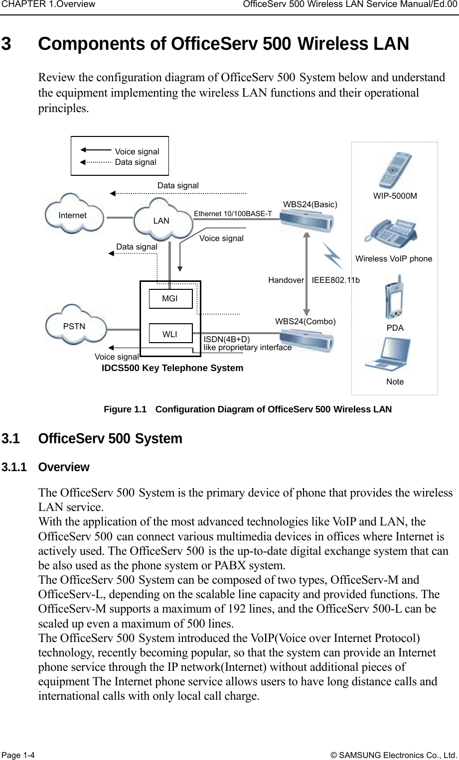
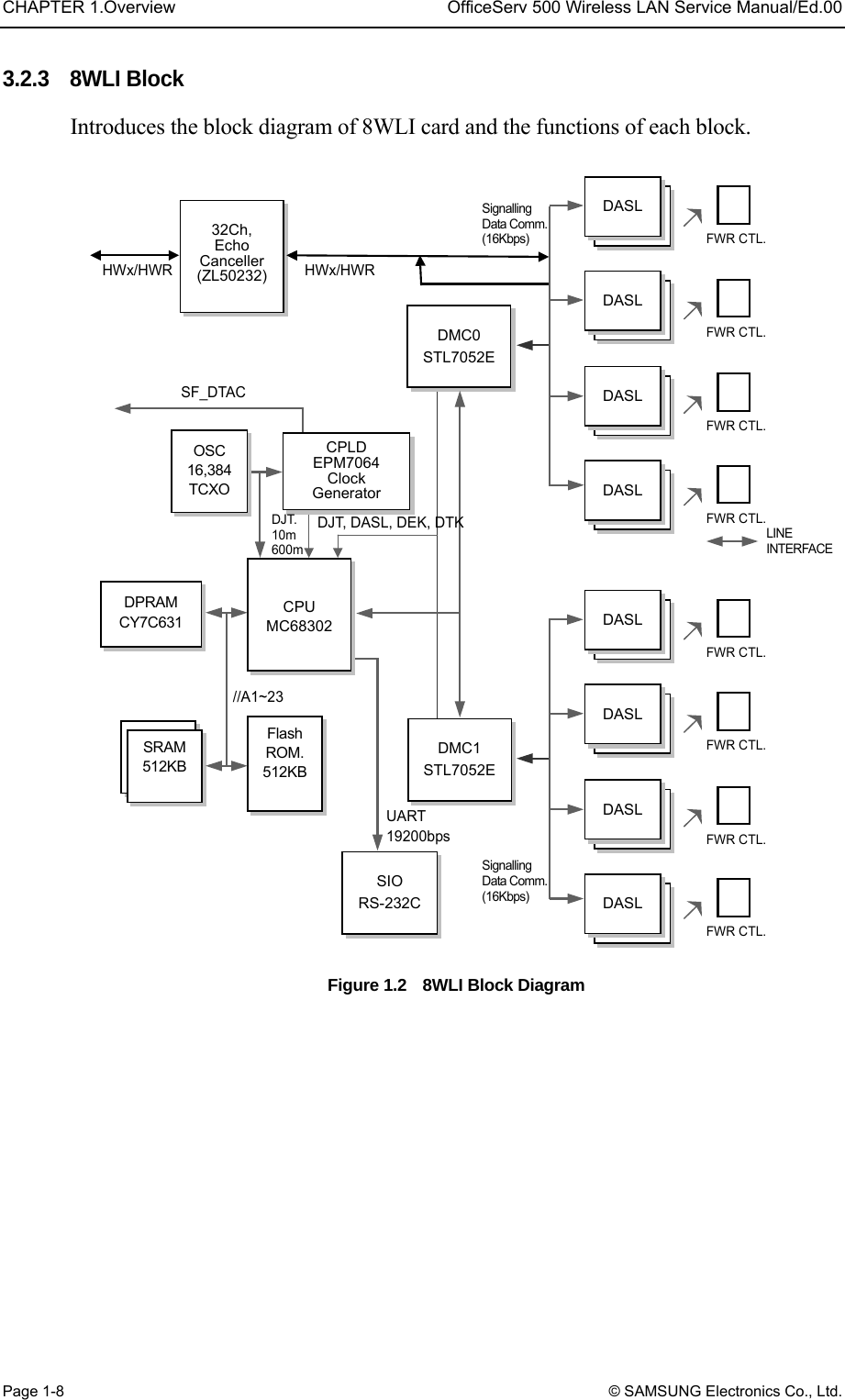
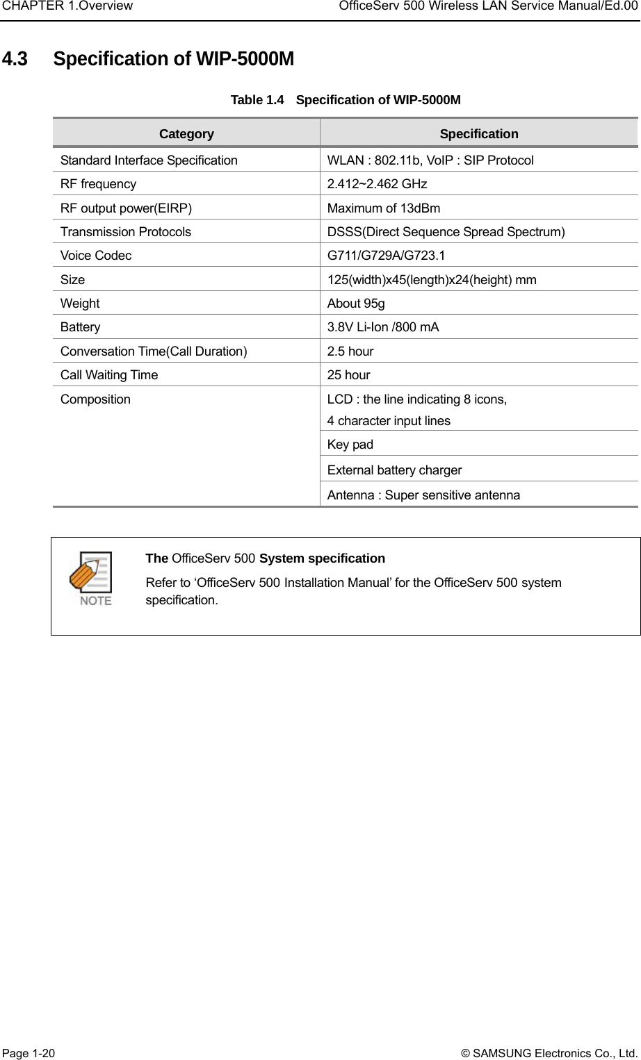
![OfficeServ 500 Wireless LAN Service Manual/Ed.00 CHAPTER 5. Maintenance © SAMSUNG Electronics Co., Ltd. Page 5-5 1.2.2 Inquiry of Config & Status With the selected [Config & Status] menu, the established value and status regarding the LAN and the WLAN can be inquired. Figure 5.3 Web screen for inquiring the WBS24 status (Config & Status) Status items are shown below. Up-Time : the passed time after booting Booting Time : the final time of WBS24 booting Version : Information on the WBS24 version DASL Status : Connection status with the 8WLI − Deactive : Not activated status of the DASL line − Active(Not Config) : DASL line is activated, and the initialized message is not received from the system. − Active(Config OK) : DASL line is activated, and the initialized message is received from the system. B-channel Status : the number of traffics being in use at present Associated Nodes : Unavailable at present](https://usermanual.wiki/Samsung-Electronics-Co/WBS24BASIC/User-Guide-384179-Page-81.png)
![CHAPTER 5. Maintenance OfficeServ 500 Wireless LAN Service Manual/Ed.00 Page 5-6 © SAMSUNG Electronics Co., Ltd. 1.2.3 Upgrading S/W With the selected [Upgrade] menu, the WBS24 software can be upgraded. At the first time connection, the user name and password will be asked. Enter the user name and password by inquiring from the system manager. (Example : a user name and password are initially set as 'wlan’) Figure 5.4 Web screen for inquiring the WBS24 status (Screen for entering password) For the software upgrade, refer to ‘2.Upgrading the WBS24 S/W’ in chapter5.](https://usermanual.wiki/Samsung-Electronics-Co/WBS24BASIC/User-Guide-384179-Page-82.png)
![OfficeServ 500 Wireless LAN Service Manual/Ed.00 CHAPTER 5. Maintenance © SAMSUNG Electronics Co., Ltd. Page 5-7 1.2.4 Restarting WBS24 By selecting the [Restart] menu, the WBS24 can be restarted. When connecting for the first time, the user name and password will be asked. Enter the user name and password by inquiring from the system manager.( Example : a user name and password are initially set as 'wlan’) When the screen as shown below is displayed, click the [Restart] button to restart the WBS24. Figure 5.5 Web screen for inquiring the WBS24 status (Restart)](https://usermanual.wiki/Samsung-Electronics-Co/WBS24BASIC/User-Guide-384179-Page-83.png)
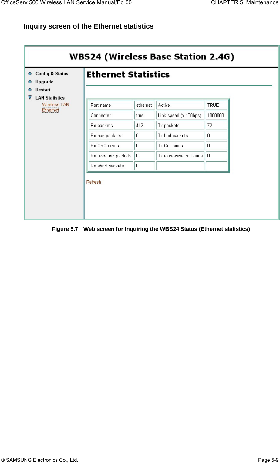
![CHAPTER 5. Maintenance OfficeServ 500 Wireless LAN Service Manual/Ed.00 Page 5-8 © SAMSUNG Electronics Co., Ltd. 1.2.5 Inquiring Statistical Information of Block LAN With the selected [LAN Statistics] menu, statistical information on data transmitted and received through the WLAN and the Ethernet can be inquired. Two sub menus will be displayed, so the statistical information by each sub-menu can be inquired. Inquiry screen of Wilress LAN statistics Figure 5.6 Web screen for inquiring the WBS24 status (Wireless LAN statistics)](https://usermanual.wiki/Samsung-Electronics-Co/WBS24BASIC/User-Guide-384179-Page-84.png)
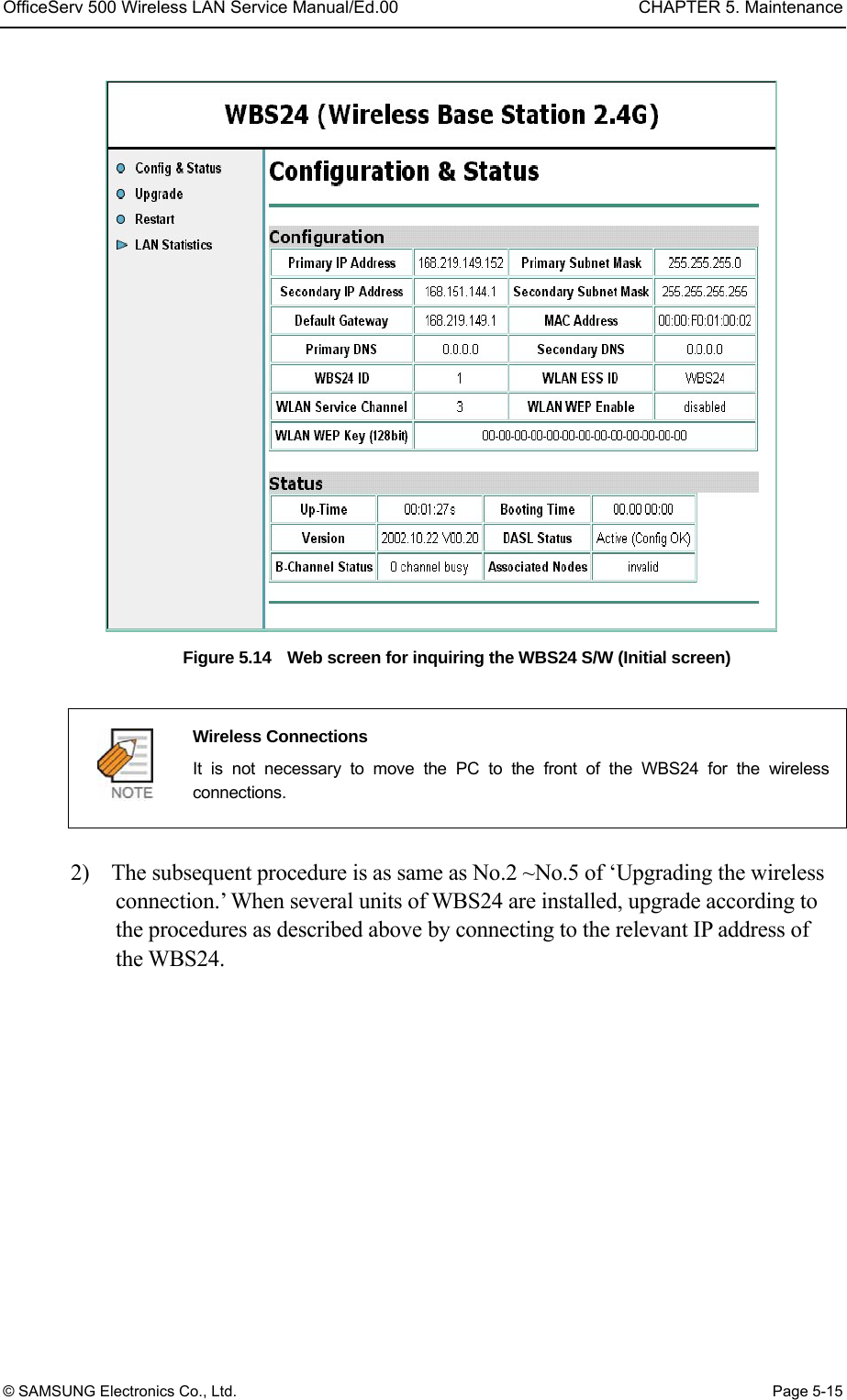
![OfficeServ 500 Wireless LAN Service Manual/Ed.00 CHAPTER 5. Maintenance © SAMSUNG Electronics Co., Ltd. Page 5-11 Figure 5.8 Web screen for upgrading the WBS24 S/W (Initial screen) Cautions against the roaming of the WBS24 If the PC is roamed to another WBS24 while upgrading, the upgrade will be interrupted and the flash memory will not be functioning. Accordingly, locate the PC as close as possible from the WBS24. To prevent roaming to another WBS24, it is recommended that all of the WBS24 power should be turned off for safety. 2) Select the [Upgrade] menu. The user name and password will be asked if connected for the first time. Enter the user name and password by inquiring from the system manager.(Example : User name, Password-wlan) Figure 5.9 Web screen for upgrading the WBS24 S/W (Screen to enter a password)](https://usermanual.wiki/Samsung-Electronics-Co/WBS24BASIC/User-Guide-384179-Page-87.png)
![CHAPTER 5. Maintenance OfficeServ 500 Wireless LAN Service Manual/Ed.00 Page 5-12 © SAMSUNG Electronics Co., Ltd. 3) If a user is authorized successfully, the following screen will show up. Click the [Indexing] button. Select the prepared upgrade file(.tar type) Figure 5.10 Web screen for inquiring the WBS24 S/W (Firmware upgrade)](https://usermanual.wiki/Samsung-Electronics-Co/WBS24BASIC/User-Guide-384179-Page-88.png)
![OfficeServ 500 Wireless LAN Service Manual/Ed.00 CHAPTER 5. Maintenance © SAMSUNG Electronics Co., Ltd. Page 5-13 4) Click the [Upgrade] menu when the following screen is displayed. At this time, click the [Upgrade] button only once. The upgrade is preceded. The required time may vary according to the WBS24 status, but it is about three or four minutes. Figure 5.11 Web screen for inquiring the WBS24 S/W (Click the [Upgrade] button) Figure 5.12 Web screen for inquiring the WBS24 S/W (In the process of upgrade)](https://usermanual.wiki/Samsung-Electronics-Co/WBS24BASIC/User-Guide-384179-Page-89.png)
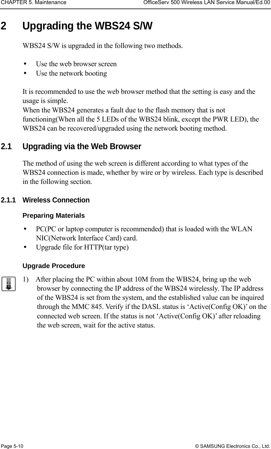
![CHAPTER 5. Maintenance OfficeServ 500 Wireless LAN Service Manual/Ed.00 Page 5-14 © SAMSUNG Electronics Co., Ltd. 5) When the upgrade is completed, the following screen will show up. The upgrade contents are not applied at this time, and it is applied when restarting the WBS24. If the upgrade contents are needed to apply immediately, click the [Restart] button and restart the WBS24. After restarting, verify the version on the web screen. Figure 5.13 Web screen for upgrading the WBS24 S/W (Firmware Upgrade Complete) 6) When several units of WBS24 are installed, repeat No.1~No.5 by moving the PC to each WBS24. 2.1.2 Wired Connection Preparing Materials PC(PC or laptop computer) that is loaded with the wire LAN port. Upgrade file for HTTP(tar type) Upgrade Procedure 1) After connecting the PC to the wired LAN, connect to the IP address of WBS24. Bring up the web browser. The IP address of the WBS24 is established at the system, and the established value can be inquired via the MMC 845. Verify if the DASL status is ‘Active(Config OK)’ on the web screen. If the status is not ‘Active(Config OK)’, reload the screen and wait for the status.](https://usermanual.wiki/Samsung-Electronics-Co/WBS24BASIC/User-Guide-384179-Page-90.png)
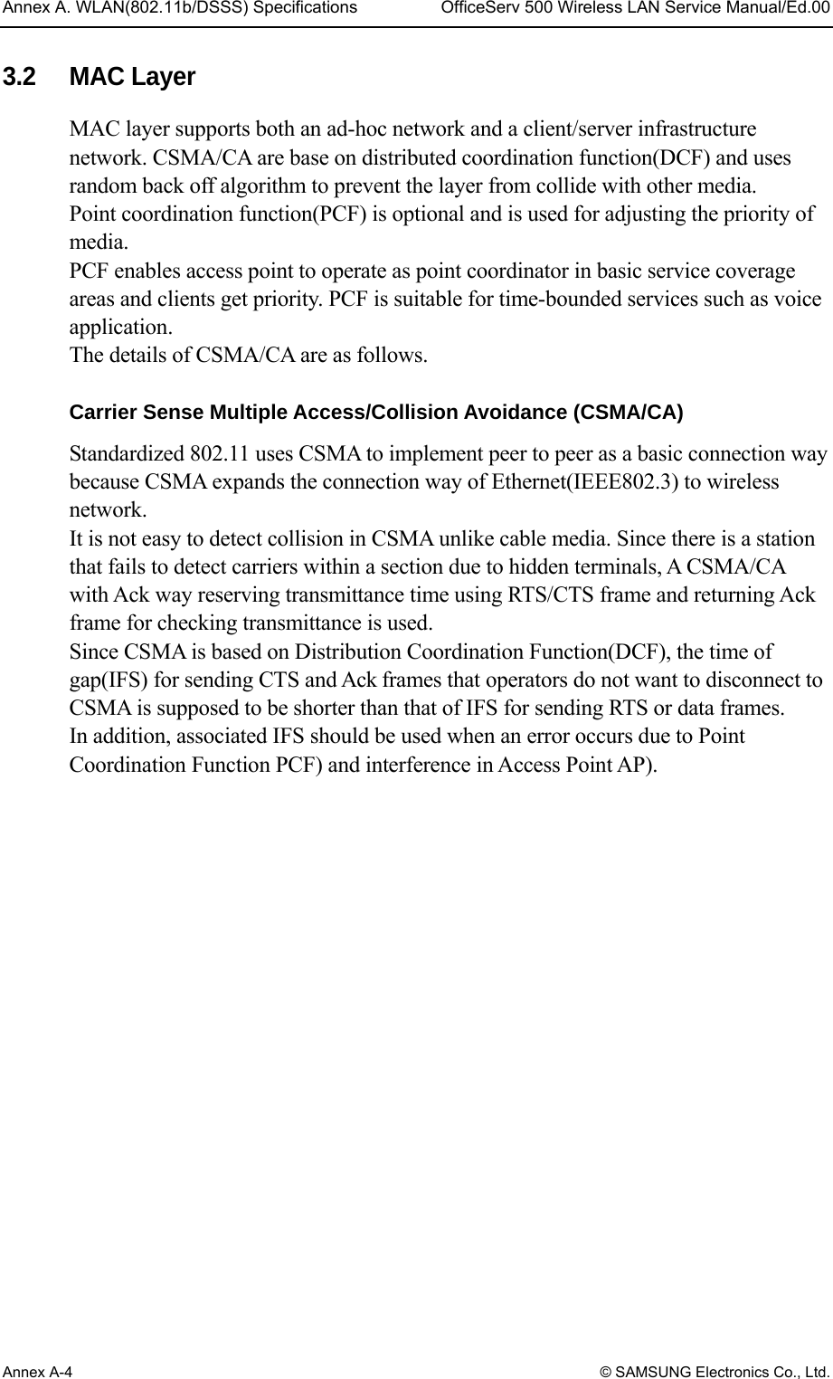
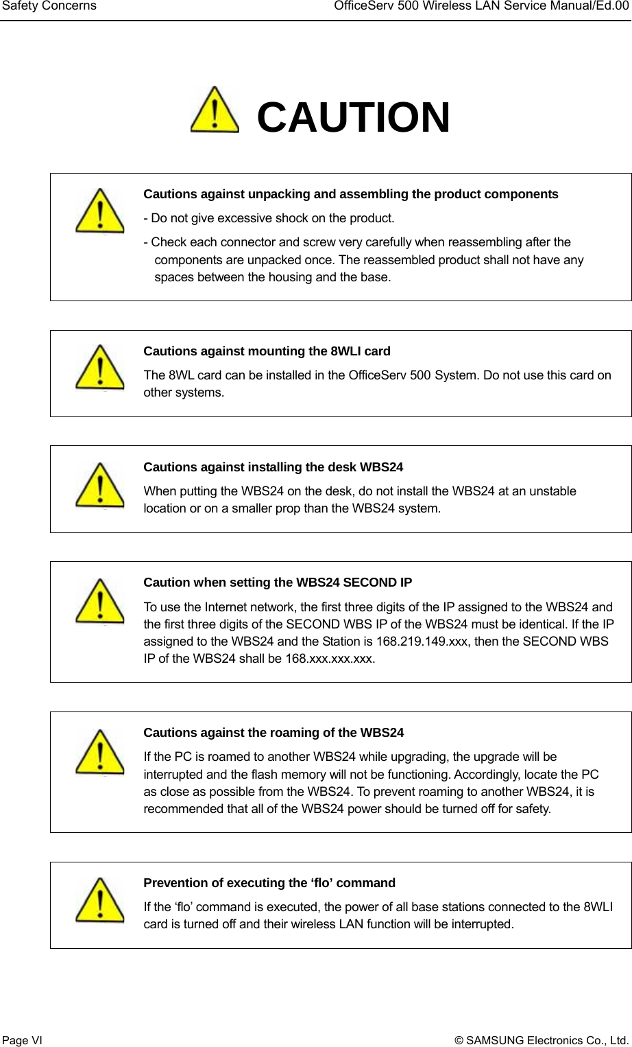
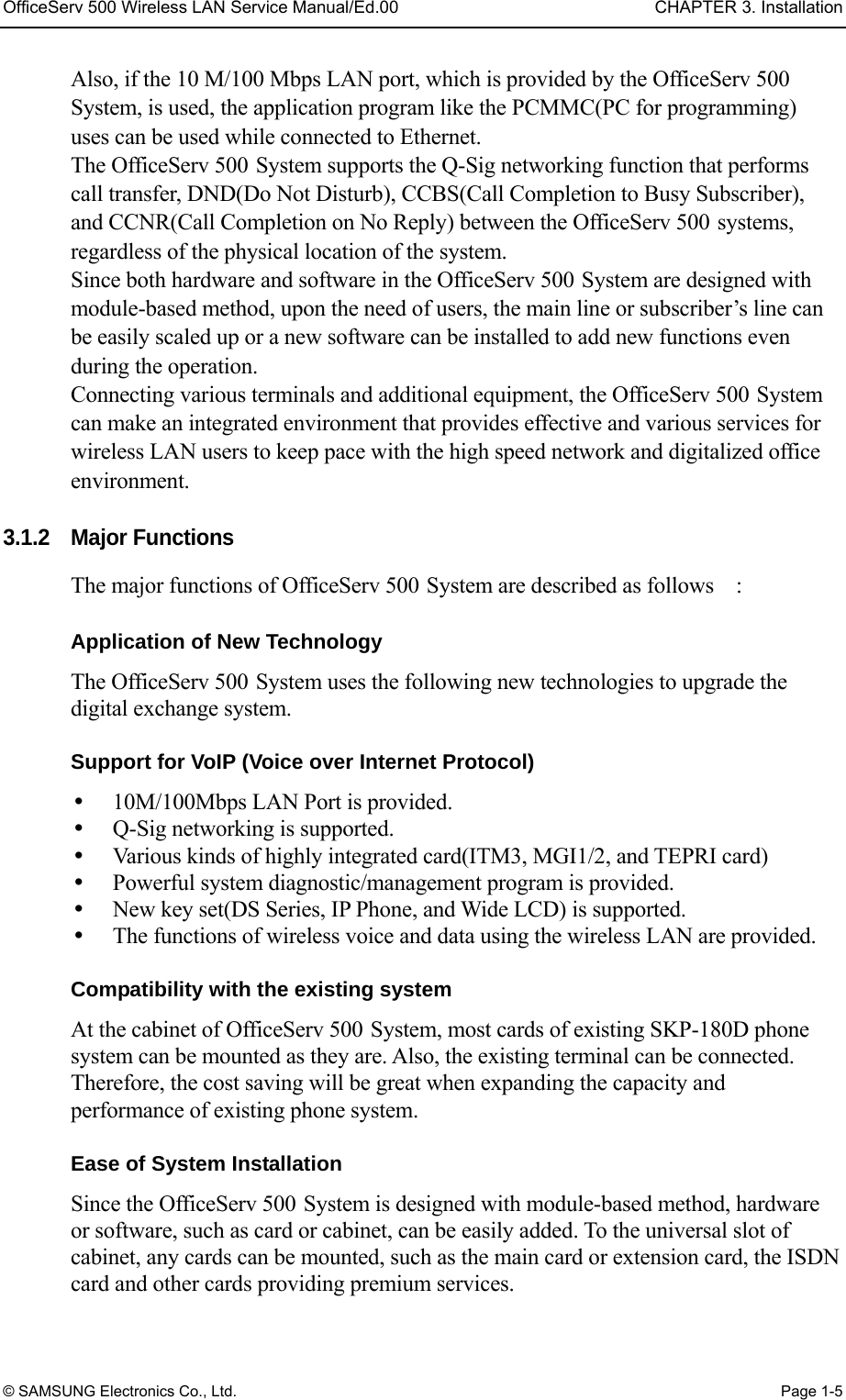
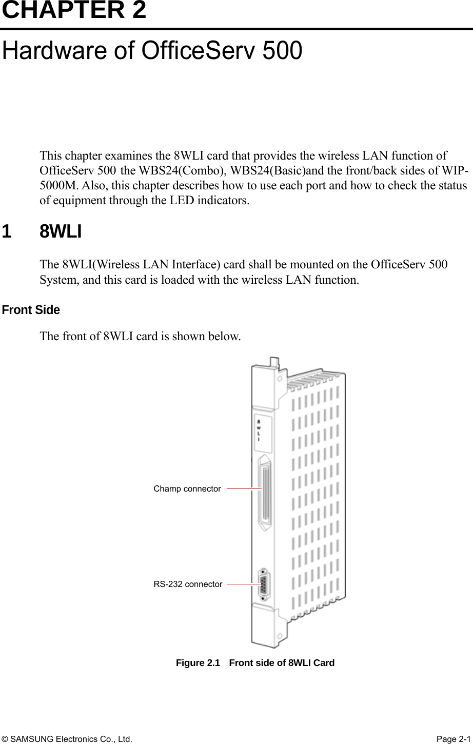
![CHAPTER 5. Maintenance OfficeServ 500 Wireless LAN Service Manual/Ed.00 Page 5-16 © SAMSUNG Electronics Co., Ltd. 2.2 Upgrading via the Network Booting This method is used to recover an error such as non-functioning flash memory. This method is impossible to upgrade wirelessly, but only through a wired LAN. If the WBS24 is connected with a wired LAN, it is possible to upgrade without any change on the WBS24. But if not the case, the wired LAN shall be connected between the WBS24 and the PC in order to upgrade the WBS24. This section describes how to upgrade the WBS24 based on the assumption that the WBS24 is connected to the wired LAN. Preparing Materials PC server with a wired LAN port Upgrade file for the network booting(bin type) Upgrade Procedure 1) Set the PC to the TFTP/BootP Server for the network booting. Set the PC by using an application program for PC. This description explains how to set up using the ‘Cabletron TFTP/BootP Services 2.0 S/W. When another S/W is used, refer to the relevant usage of S/W. The following describes how to set up ‘Cabletron TFTP/BootP Services 2.0 S/W’. Receive the program and execute the Setup procedure to set up the program. Execute the program(When designating a default directory, execute ‘C:\TFTPBOOT\BIN\TFTPBOOT.EXE’) and click the [Start Download] button. Enter IP of the installed PC and click the [BootP Server] button. Figure 5.15 Upgrading the WBS24 S/W via the Network Booting (1) # Enter the IP of installed PCand press the Enter key $Press the BootP Server button " Press the Start Download button](https://usermanual.wiki/Samsung-Electronics-Co/WBS24BASIC/User-Guide-384179-Page-92.png)
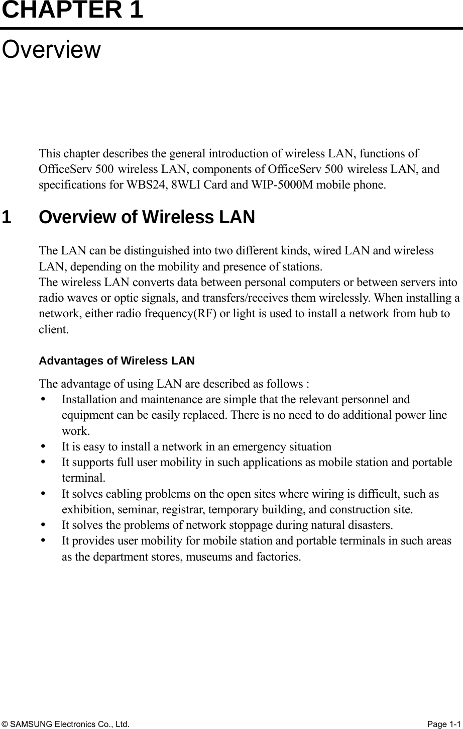
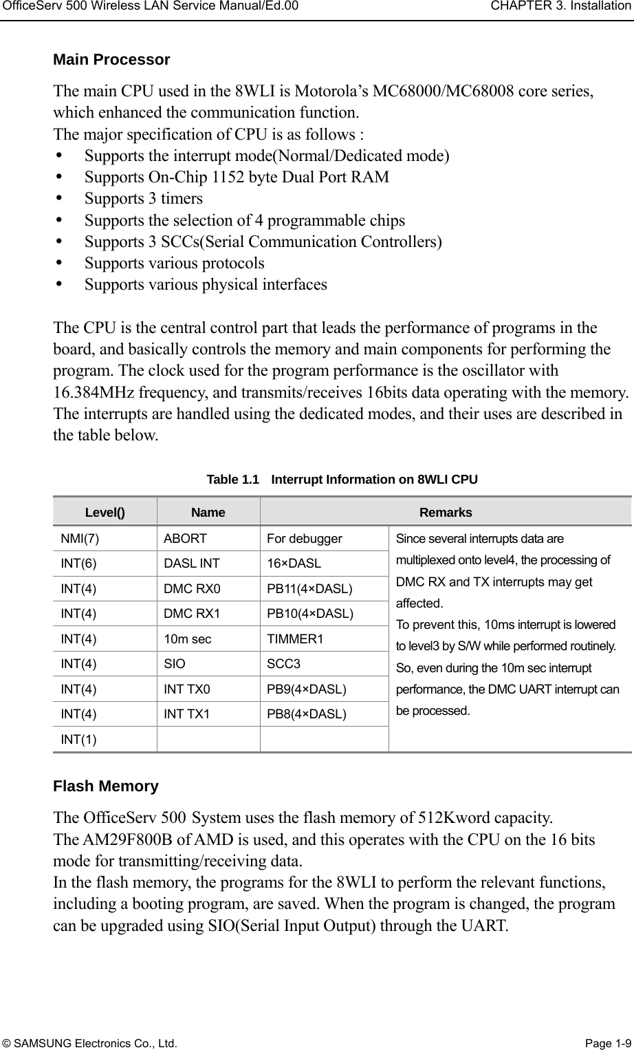
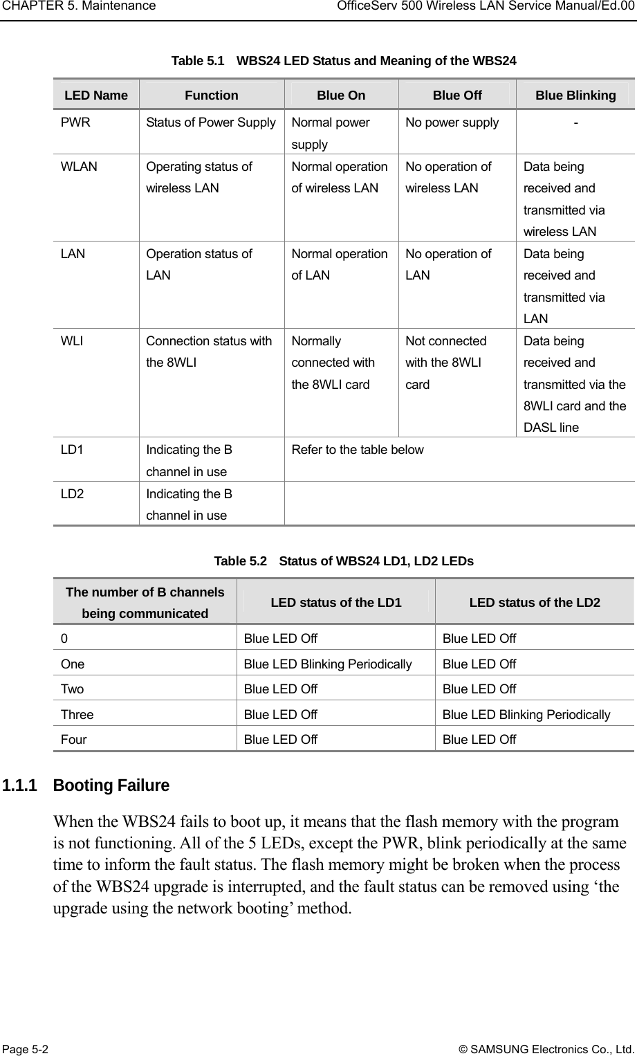
![OfficeServ 500 Wireless LAN Service Manual/Ed.00 CHAPTER 5. Maintenance © SAMSUNG Electronics Co., Ltd. Page 5-17 Then the following screen will show up. After entering the MAC Address, IP Address and File Name, click the [Update] button. Figure 5.16 Upgrading the WBS24 S/W via the Network Booting (2) 2) Turn off the power of WBS24 and turn it on again. Then upgrading is performed automatically. If upgrading is not performed and the error LED is repeated, verify the connection status of the wired LAN or the setting status of TFTP/BootP server. If upgrading is normally completed, the WLAN, LAN and WLI LEDs will be turned on as a Blue color after booting. Verify the S/W version on the web screen. " Enter the MAC address of AP where to receive the file from $ Enter the pathe and name of the file that AP will receive, or select the file by clicking the browserat the botton % Click the Update button # Enter the IP that AP is to be assigned for](https://usermanual.wiki/Samsung-Electronics-Co/WBS24BASIC/User-Guide-384179-Page-93.png)
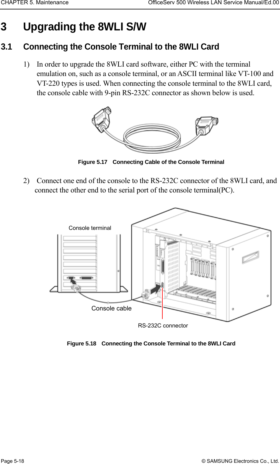
![OfficeServ 500 Wireless LAN Service Manual/Ed.00 CHAPTER 5. Maintenance © SAMSUNG Electronics Co., Ltd. Page 5-19 3.2 Configuring the Console Terminal The values of the console terminal to be used are configured as shown below. Emulation : compatible with VT-100/ANSI Bits per second : 9600 bps Stop bit : 1 Data bit : 8 Parity bit : None Flow control : None The method of setting the console terminal can be different according to the terminal type or the management system. The file(WLIROM.HEX, MWLIROM.HEX) is loaded to the 8WLI card in the following two methods. Using the Tera terminal of the Windows 95/98 operating system Using the ‘qmodem.exe’ on the DOS window 3.2.1 Loading a File with the Tera Terminal 1) Turn on the PC(Windows95/98 O/S). 2) Execute the Tera terminal program 3) If console terminal is not connected, ‘Cannot open COM1’ message windows appears. Then, Click the <file><New Connection> to open the new window. 4) Select the <Setup><Serial Port> from the new window, and set as shown below then click the [Ok] button. Bits per second : 9600 bps Stop bit : 1 Data bit : 8 Parity bit : None Flow control : None 5) Then a new Tera terminal will show up.](https://usermanual.wiki/Samsung-Electronics-Co/WBS24BASIC/User-Guide-384179-Page-95.png)
![CHAPTER 5. Maintenance OfficeServ 500 Wireless LAN Service Manual/Ed.00 Page 5-20 © SAMSUNG Electronics Co., Ltd. Upgrading a New Software The 8WLI card can upgrade the software by downloading WLIROM HEX file and MWLIROM.HEX file via the console terminal. After storing both files in the console terminal, download them following the method below. 1) When the 8WLI card is normally operated, the following message will show up. Click the [ENTER] key. VoWLAN Console <8-Port WLI Board> 2) Enter the ‘flo’ command at the prompt and click the [ENTER] key, the following massage will show up. <WLI>flo ================== Select One ======================= [1] Single WLI HEX FILE Loading <Addr = 0x00110000> [2] Multi WLI HEX FILE Loading <Addr = 0x00190000> [R] Restart Prevention of executing the ‘flo’ command If the ‘flo’ command is executed, the power of all base stations connected to the 8WLI card is turned off and their wireless LAN function will be interrupted. 3) Select ‘1’ and load the WLIROM.HEX file, from the PC to the 8WLI card. Then the following message will show up. Selected 1> Single- WLI HEX FILE Loading Please Start Loading!! 4) Click the ‘Send file’ on the File Menu of the Tera terminal window. 5) Then the <Sending the text file> window will show up. Select the WLIROM HEX file and click the [Ok] button. 6) While the WLIROM HEX file is being transmitted to the 8WLI card, the transmitted contents will be indicated on the screen. If the file transmission is completed, information on the transmitted HEX file will show up. It takes about fifteen minutes to send the file to the 8WLI card.](https://usermanual.wiki/Samsung-Electronics-Co/WBS24BASIC/User-Guide-384179-Page-96.png)
![OfficeServ 500 Wireless LAN Service Manual/Ed.00 CHAPTER 5. Maintenance © SAMSUNG Electronics Co., Ltd. Page 5-21 =========HEX FILE INFORMATION ====================== HEX FILE START ADDR = 0x00110000 HEX FILE END ADDR = 0x0013465D HEX FILE TOTAL ADDR = 0x0002465D =========== FLASH MEMORY WRITE START=============== STEP 1. SECTOR ERASE SUCCESS STEP 2. PROGRAM WRITE SUCCESS =========== FLASH MEMORY WRITE END =============== Please [R] key to Restart or [L] key to Loading Again !! 7) Enter ‘L’, and then the following menu will show up. Enter ‘2 to transmit the MWLIROM.HEX file to the 8WLI card. <WLI> flo ============ Select One ================= [1] Single WLI HEX FILE Loading <Addr = 0x00110000> [2] Multi WLI HEX FILE Loading <Addr = 0x00190000> [3] Restart 8) Click the ‘Send file’ on the File Menu of the Tera terminal window. 9) Then the <Sending the text file> window will show up. Select the MWLIROM.HEX file and click the [Ok] button. 10) Enter ‘R’. If two HEX files are properly transmitted, the following screen will show up. ************************************************* * VoWLAN Console <8-Port WLI Board > * *************************************************](https://usermanual.wiki/Samsung-Electronics-Co/WBS24BASIC/User-Guide-384179-Page-97.png)
![CHAPTER 5. Maintenance OfficeServ 500 Wireless LAN Service Manual/Ed.00 Page 5-22 © SAMSUNG Electronics Co., Ltd. 3.2.2 Loading the File with Qmodem 1) Exeute qmodem.exe on the DOS window. This description explains how to load a file if the installed qmodem version is ‘SST V3.1a’. If another qmodem version is used, refer to the relevant manual. 2) Click the [Alt+P] key to set the modem value. Then the <Set Modem Speed> window will show up. 3) Click the [ENTER] key, and check if the <8WLI> prompt is generated or not on the main window. If the <8WLI> prompt is not generated, the user shall verify the cable status, the traffic port status of PC, and the setting status of the modem configuration parameter. 4) Enter the ‘flo’ command at the <8WLI> prompt. Then a new message will be displayed. <WLI> flo ============== Select One ============= [1] Single WLI HEX FILE Loading <Addr = 0x00110000> [2] Multi WLI HEX FILE Loading <Addr = 0x00190000> [3] Restart 5) Enter ‘1’ and select [1], and then the following message will be displayed on the main window. Selected 1> Single – WLI HEX FILE Loading Please Start Loading !! 6) Click the [Page-Up] to load the selected ROM file to the 8WLI card. Then the following message will show up. **[ Upload Protocols]** * A) Ascii * * X) Xmodem * * C) Xmodem CRC * *R) Relaxed Xmodem * *Y) 1K-Xmodem * *B) Ymodem Batch * *Your choice ? * **********************](https://usermanual.wiki/Samsung-Electronics-Co/WBS24BASIC/User-Guide-384179-Page-98.png)
![OfficeServ 500 Wireless LAN Service Manual/Ed.00 CHAPTER 5. Maintenance © SAMSUNG Electronics Co., Ltd. Page 5-23 7) Select the < A)Ascii > menu by clicking [A] button on the <Upload Protocols> window. 8) Enter the path of the file to be uploaded. For instance, if the file to be uploaded is located as same as the qmodem file, enter the ‘.\WLIROM.HEX’. If the file to be uploaded is not located as same as the qmodem file, enter the file name as well as the whole path of the upload file. 9) If enter the file name, following ‘Upload Files(Transmit)’ window appears ***********************Upload Files(Transmit)********************* Enter the transfer mode: 1)Prompted 2) Time delay 3) No delay **************************************************************** 10) Enter ‘3’ and then the following 11) message will be displayed. It is possible to verify the upload status by scrolling the data. 11) If the upload is completed, the following HEX information will be displayed. The displayed information can be different according to the software version of the 8WLI. If ‘Flash Memory Write End’is displayed, it means that uploading is successfully completed. ===========HEX FILE INFORMATION ========== HEX FILE START ADDR = 0x00110000 HEX FILE END ADDR = 0x00013465D HEX FILE TOTAL LEN = 0x0002465D ------------ FLASH MEMORY WRITE START ------------- STEP 1. SECTOR ERASE SUCCESS STEP 2. PROGRAM WRITE SUCCESS ---------- FLASH MEMORY WRITE END --------------- Please [R] key to Restart or [L] key to Loading Again !! 12) Click [L] and then the following message will show up. <WLI>file ========== Select One ============= [1] Single WLI HEX FILE Loading <Addr = 0x00110000> [2] Multi WLI HEX FILE Loading <Addr = 0x00190000> [R] Restart](https://usermanual.wiki/Samsung-Electronics-Co/WBS24BASIC/User-Guide-384179-Page-99.png)
![CHAPTER 5. Maintenance OfficeServ 500 Wireless LAN Service Manual/Ed.00 Page 5-24 © SAMSUNG Electronics Co., Ltd. 13) Select [2] menu to load the WLIROM..HEX file. Then the following message will show up. Selected 1> Single- WLI HEX FILE Loading Please Start Loading !! 14) Perform No.6)~No.10) as shown above and upload the MWLIROM.HEX file. Select the MWLIROM.HEX file instead of the WLIROM.HEX file. After uploading the MWLIROM.HEX file, the following message will show up. ================HEX FILE INFORMATION ==================== HEX FILE START ADDR = 0x00110000 HEX FILE END ADDR = 0x0012465D HEX FILE TOTAL LEN = 0x0002465D ------------ FLASH MEMORY WRITE START --------------------- STEP 1. SECTOR ERASE SUCCESS STEP 2. PROGRAM WRITE SUCCESS ----------- FLASH MEMORY WRITE END ---------------------- Please [R] key to Restart or [L] key to Loading Again !! The message can be different according to the WLI software version. If ‘Flash Memory Write End’ shows up, it means that uploading is successfully completed. 15) Click [R] and restart the 8WLI card. If the file is normally transmitted, the following main window will show up. ****************************************** * VoWLAN Console < 8- Port WLI Board > * ******************************************](https://usermanual.wiki/Samsung-Electronics-Co/WBS24BASIC/User-Guide-384179-Page-100.png)