Samsung Electronics Co WBS24BASIC WLAN ACCESS POINT User Manual
Samsung Electronics Co Ltd WLAN ACCESS POINT
USERS MANUAL

Ed. 00
OfficeServ 500 Wireless LAN
Service Manual
9. 2003.

COPYRIGHT
This manual is proprietary to SAMSUNG Electronics Co., Ltd. and is protected by copyright.
No information contained herein may be copied, translated, transcribed or duplicated for any
commercial purposes or disclosed to third parties in any form without the prior written consent of
SAMSUNG Electronics Co., Ltd.
TRADEMARKS
Product names mentioned in this document may be trademarks and/or registered trademarks of
their respective companies.
This manual should be read before the installation and operation, and the operator should correctly install
and operate the product by using this manual.
This manual may be changed for the system improvement, standardization and other technical reasons without prior
notice.
For further information on the updated manual or have a question the content of manual, contact Document Center at
the address below .
Address : Document Center 2nd Floor IT Center. Dong-Suwon P.O. Box 105, 416, Metan-3dong Paldal-gu,
Suwon-si, Gyeonggi-do, Korea 442-600
e-mail : manual@samsung.com
Or contact Call Center at the telephone below if you have any questions or concerns regarding the operation of your
system.
Phone : 81-1588-4141
http://www.samsungnetwork.com
©2003 SAMSUNG Electronics Co., Ltd. All rights reserved.

INTRODUCTION
© SAMSUNG Electronics Co., Ltd. Page I
Purpose
This service description introduces WBS24, 8WLI card, and WIP-5000M mobile phone
that provide the wireless LAN function of OfficeServ 500 System. This manual contains
information on installation, troubleshooting method, and MMC setting method.
Document Content and Organization
This manual is composed of 5 chapters. Each chapter is summarized as follows :
CHAPTER 1. Overview
Overview of general wireless LAN
Overview of OfficeServ 500 wireless LAN functions
Diagram of system configuration
Specifications of WBS24, 8WLI card, WIP-5000M mobile phone
CHAPTER 2. Hardware of OfficeServ 500
8WLI card & the front and back sides of WBS24
Usage for each port and how to read the status of hardware through LEDs
CHAPTER 3. Installation
How to install the 8WLI card in the OfficeServ 500 System
How to install WBS24
How to set DB for wireless LAN service
How to register WIP-5000M
How to select the location of WBS24
CHAPTER 4. MMC Programming
How to program MMC related to the wireless LAN functions.
Introduction OfficeServ 500 Wireless LAN Service Manual/Ed.00
Page II © SAMSUNG Electronics Co., Ltd.
CHAPTER 5. Maintenance
How to troubleshoot problems through LED states of WBS24
How to check the WBS24 status through a web browser
How to upgrade the software of WBS24
How to upgrade the software of 8WLI
ANNEX A. WLAN (802.11b/DSSS) Specifications
Features and Specifications of the 802.11b/DSSS wireless LAN standard
ANNEX B. Antenna Beam Pattern of WBS24
Antenna Beam Pattern of WBS24
ABBREVIATION
The frequently used acronyms and their meanings in this manual are all collected.
Conventions
The following special paragraphs are used in this document to point out information that
must be read. This information may be set-off from the surrounding text, but is always
preceded by a bold title in capital letters. The three categories of these special paragraphs
are :
WARNING
Indicate a potentially hazardous situation which if not avoided, could result in death or
serious injury.
CAUTION
Indicate a potentially hazardous situation which if not avoided, may result in minor or moderate
injury. It may also be used to alert against unsafe practices.
NOTE
Indicates additional information as a reference
OPERATION PROCEDURES
Indicates the operation procedures that should be executed in order.

OfficeServ 500 Wireless LAN Service Manual/Ed.00 Introduction
© SAMSUNG Electronics Co., Ltd. Page III
Reference
OfficeServ 500 Installation Description
Introduces information on how to install the OfficeServ 500 System.
OfficeServ 500 Programming Description
Introduces how to program MMC that sets up various functions of OfficeServ 500 System
from a digital phone.
DS-6012L/5012L Phone Manual
This is a user’s manual for the users of DS-6012L and DS-5012L, the digital phone that
can be used in connection with the OfficeServ 500 System, and for the users of ITP-5012L,
the IP phone.
ITP-5012L Phone Manual
This is a user’s manual for the users of ITP-5012L, the IP phone that can be used in
connection with the OfficeServ 500 System.
DS-5000D Series Phone Manual
This is a user’s manual for the users of DS-5038D, DS-5012D and DS-5014D,
the digital phone that can be used in connection with the OfficeServ 500 System.
ITP-5000D Series Phone Manual
This is a user’s manual for the users of ITP-5021D and ITP-5014D, the IP phone that can
be used in connection with the OfficeServ 500 System.
WIP-5000M User’s Manual
This is a user’s manual for the users of WIP-5000M, the mobile phone of wireless LAN
provided from the OfficeServ 500 System.
Revision History
EDITION DATE OF ISSUE REMARKS
00 9. 2003. First Edition

Introduction OfficeServ 500 Wireless LAN Service Manual/Ed.00
Page IV © SAMSUNG Electronics Co., Ltd.
Regulatory Information
- FCC Information
This equipment has been tested and found to comply with limits for a class B digital device.
Pursuant to Part 15 of the FCC Rules. These limits are designed to provide reasonable
Protection against harmful interference in a residential installation.
This equipment can generates, uses, and radiate radio frequency energy and, if not
installed and used in accordance with the instructions, may cause harmful interference to
radio communications. However, there is no guarantee that interference will not occur in a
particular installation.
If this equipment does cause unacceptable interference to radio and television reception,
which can be determined by turning the equipment off and on, the user is encouraged to
try to correct the interference by one or more of the following measures.
Reorient or relocate the receiving antenna.
Increase the separation between the equipment and receiver.
Connect the equipment into an outlet on a circuit different from that to which the receiver
is connected.
Consult the dealer or an experienced Radio/TV technician for help.
Caution
Changes or modifications not expressly approved by the party responsible for
compliance could void the user’s authority to operate the equipment.
The antenna used for this transmitter must be installed to provide a separation distance
of at least 20cm from all persons and must not be co-located or operation in conjunction
With any other antenna or transmitter
SAFETY CONCERNS
© SAMSUNG Electronics Co., Ltd. Page V
For product safety and correct operation, the following information must be given to
the operator/user and shall be read before the installation and operation.
Symbols
Caution
Indication of a general caution
Restriction
Indication for prohibiting an action for a product
Instruction
Indication for commanding a specifically required action
Safety Concerns OfficeServ 500 Wireless LAN Service Manual/Ed.00
Page VI © SAMSUNG Electronics Co., Ltd.
Caution
Cautions against unpacking and assembling the product components
- Do not give excessive shock on the product.
- Check each connector and screw very carefully when reassembling after the
components are unpacked once. The reassembled product shall not have any
spaces between the housing and the base.
Cautions against mounting the 8WLI card
The 8WL card can be installed in the OfficeServ 500 System. Do not use this card on
other systems.
Cautions against installing the desk WBS24
When putting the WBS24 on the desk, do not install the WBS24 at an unstable
location or on a smaller prop than the WBS24 system.
Caution when setting the WBS24 SECOND IP
To use the Internet network, the first three digits of the IP assigned to the WBS24 and
the first three digits of the SECOND WBS IP of the WBS24 must be identical. If the IP
assigned to the WBS24 and the Station is 168.219.149.xxx, then the SECOND WBS
IP of the WBS24 shall be 168.xxx.xxx.xxx.
Cautions against the roaming of the WBS24
If the PC is roamed to another WBS24 while upgrading, the upgrade will be
interrupted and the flash memory will not be functioning. Accordingly, locate the PC
as close as possible from the WBS24. To prevent roaming to another WBS24, it is
recommended that all of the WBS24 power should be turned off for safety.
Prevention of executing the ‘flo’ command
If the ‘flo’ command is executed, the power of all base stations connected to the 8WLI
card is turned off and their wireless LAN function will be interrupted.
CAUTION

OfficeServ 500 Wireless LAN Service Manual/Ed.00 Introduction
© SAMSUNG Electronics Co., Ltd. Page VII
Cautions against handling the board
When connecting a line cord after a board is dismantled, do not place a board near
metal and conductive objects.
Prevention of Electrostatic Hazards
When handling an electric component, wear an anti-static wrist strap or discharge the
electrostatics from your body by touching a grounded object periodically.

Safety Concerns OfficeServ 500 Wireless LAN Service Manual/Ed.00
Page VIII © SAMSUNG Electronics Co., Ltd.
This page is intentionally left blank.

TABLE OF CONTENTS
© SAMSUNG Electronics Co., Ltd. Page IX
TINTRODUCTION
UPurposeU...................................................................................................................................I
UDocument Content and OrganizationU......................................................................................I
UConventionsU............................................................................................................................II
UReferenceU..............................................................................................................................III
SAFETY CONCERNS
URevision HistoryU.....................................................................................................................III
USymbolsU................................................................................................................................. V
UCautionU................................................................................................................................. VI
CHAPTER 1. Overview
U1U UOverview of Wireless LANU............................................................................................... 1-1
U2U UOverview of OfficeUServ 500 UWireless LANU..................................................................... 1-2
U3U UComponents of UOfficeServ 500U Wireless LANU............................................................... 1-4
U3.1 U OfficeServ 500 U SystemU............................................................................................. 1-4
U3.2U U8WLIU .......................................................................................................................... 1-7
U3.3 U UWBS24 (Combo)U.......................................................................................................1-11
U3.4U UWBS24 (Basic)U........................................................................................................ 1-14
U3.5U UWIP-5000MU.............................................................................................................. 1-17
U4U USpecification of UOfficeServ 500U Wireless LANU............................................................ 1-19
U4.1U USpecification of Wireless LANU.................................................................................. 1-19
U4.2U USpecification of WBS24 (Combo/Basic)U.................................................................. 1-19
U4.3 U USpecification of WIP-5000MU.................................................................................... 1-20

Table of Contents OfficeServ 500 Wireless LAN Service Manual/Ed.00
Page X © SAMSUNG Electronics Co., Ltd.
CHAPTER 2. Hardware of OfficeServ 500
U1U U8WLIU................................................................................................................................... 2-1
U2U UWBS24 (Combo)U................................................................................................................ 2-2
U3U UWBS24 (Basic)U..................................................................................................................2-5
CHAPTER 3. Installation
U1U UInstallation ProcedureU...................................................................................................... 3-1
U2U UMounting the 8WLIU............................................................................................................ 3-2
U3U UMounting the WBS24U........................................................................................................ 3-4
U3.1U UWall Type of WBS24U.................................................................................................. 3-4
U3.2U UDesk Type of WBS24U................................................................................................. 3-7
U4U UConnecting the 8WLI with the WBS24U............................................................................ 3-8
U5U USetting the System DBU................................................................................................... 3-10
U5.1U USetting the System KEYU.......................................................................................... 3-10
U5.2U USetting the System IDU.............................................................................................. 3-10
U5.3U USetting the WBS24U.................................................................................................. 3-10
U5.4U UAssigning a terminal IPU............................................................................................ 3-11
U5.5U UAuthorizing the Terminal RegisterU............................................................................ 3-11
U6U URegistering/Clearing the WIP-5000M TerminalU............................................................ 3-12
U6.1U URegistering a WIP-5000MU........................................................................................ 3-12
U6.2 U UClearing a WIP-5000MU............................................................................................ 3-12
U7U UPositioning the WBS24U.................................................................................................. 3-13
U7.1U UCell OverviewU........................................................................................................... 3-13
U7.2U UData Transmission Rate on Terminal LocationU........................................................ 3-15
CHAPTER 4. MMC Programming
U1U UBefore ProgrammingU........................................................................................................ 4-1
U1.1U UProgramming OverviewU............................................................................................. 4-1
U1.2U UProgramming ButtonU.................................................................................................. 4-2
U1.3U UCautions when ProgrammingU.................................................................................... 4-2
U1.4U UProgramming ProcedureU............................................................................................ 4-3
U2U UProgrammingU.................................................................................................................... 4-4
U2.1U USetting the MMC845 8WLI ParameterU....................................................................... 4-4
U2.2 U USetting the MMC846 WIP InformationU....................................................................... 4-9
U2.3U UResetting the MMC847 WIPU........................................................................................11

OfficeServ 500 Wireless LAN Service Manual/Ed.00 Table of Contents
© SAMSUNG Electronics Co., Ltd. Page XI
U2.4U USetting the MMC848 WIP ListsU.................................................................................4-11
U2.5 Setting the MMC849 WLI REGISTU.......................................................................... 4-12
U2.6U USetting the MMC830 Ethernet ParametersU............................................................. 4-14
U2.7 U USetting the MMC831 MGI ParametersU.................................................................... 4-17
CHAPTER 5. Maintenance
U1U UVerifying the Status of WBS24U........................................................................................ 5-1
U1.1 U UStatus inquiry via the LED Status IndicatorsU.............................................................. 5-1
U1.2U UStatus Inquiry via a Web BrowserU.............................................................................. 5-4
U2U UUpgrading the WBS24 S/WU............................................................................................ 5-10
U2.1U UUpgrading via the Web BrowserU.............................................................................. 5-10
U2.2U UUpgrading via the Network BootingU......................................................................... 5-16
U3U UUpgrading the 8WLI S/WU................................................................................................ 5-18
U3.1U UConnecting the Console Terminal to the 8WLI CardU............................................... 5-18
U3.2U UConfiguring the Console TerminalU........................................................................... 5-19
ANNEX A. WLAN (802.11b/DSSS) Specifications
U1U UFeature Comparison with Other StandardsU.......................................................Annex A-1
U2U UOperating Frequency by Channel and CountryU.................................................Annex A-2
U3U UDefinitions and Features by LayerU......................................................................Annex A-3
U3.1U UPhysical LayerU................................................................................................Annex A-3
U3.2U UMAC LayerU......................................................................................................Annex A-4
U3.3U UData Link/Network LayerU................................................................................Annex A-5
U4U UWLAN Frame StructureU........................................................................................Annex A-7
U4.1U UShort PLCP PPDU Frame FormatU..................................................................Annex A-7
U4.2U ULong PLCP PPDU Frame FormatU..................................................................Annex A-7
U5U UQuality of Service (QoS)U......................................................................................Annex A-8
U6U USecurityU..................................................................................................................Annex A-8
ANNEX B. Antenna Beam Pattern of WBS24
ABBREVIATION
UA~NU ................................................................................................................. Abbreviation-1
UP~WU ................................................................................................................. Abbreviation-2

Table of Contents OfficeServ 500 Wireless LAN Service Manual/Ed.00
Page XII © SAMSUNG Electronics Co., Ltd.
LIST OF FIGURES
UFigure 1.1 Configuration Diagram of U OfficeServ 500 U Wireless LANU............................ 1-4
UFigure 1.2 8WLI Block DiagramU..................................................................................... 1-8
UFigure 1.3 Block Diagram of WBS24 WBS24 (Combo)U............................................... 1-14
UFigure 1.4 Block Diagram of WBS24 WBS24 (Basic)U.................................................. 1-17
UFigure 1.5 Block Diagram of WIP-5000MU..................................................................... 1-18
UFigure 2.1 Front side of 8WLI CardU................................................................................ 2-1
UFigure 2.2 Front side of WBS24 (Combo)U...................................................................... 2-2
UFigure 2.3 Back side of WBS24 (Combo)U...................................................................... 2-4
UFigure 2.4 Front side of WBS24 (Basic)U......................................................................... 2-5
UFigure 2.5 Back side of WBS24 (Basic)U......................................................................... 2-6
UFigure 3.1 The Wireless LAN Installation ProcedureU..................................................... 3-1
UFigure 3.2 Mounting the 8WLI Card (1)U.......................................................................... 3-2
UFigure 3.3 Mounting the 8WLI Card (2)U.......................................................................... 3-3
UFigure 3.4 Mounting the WBS24 on a Concrete Wall-Drilling a HoleU............................. 3-5
UFigure 3.5 Mounting the WBS24 on a Concrete Wall-Inserting the Plastic AnchorU....... 3-5
UFigure 3.6 Mounting the WBS24 on a Concrete Wall-Tightening the ScrewU................. 3-5
UFigure 3.7 Mounting the WBS24 on a Concrete WallU.................................................... 3-6
UFigure 3.8 Mounting the WBS24 on a concrete wall-Attach the WBS24 to its PropU...... 3-6
UFigure 3.9 Installing a Desk WBS24U.............................................................................. 3-7
UFigure 3.10 RJ-45 cableU................................................................................................... 3-8
UFigure 3.11 Connecting the WBS24 with the 8WLI cardU.................................................. 3-9
UFigure 3.12 The Cell Boundary of WBS24U..................................................................... 3-13
UFigure 3.13 Single Cell ConfigurationU............................................................................ 3-14
UFigure 3.14 Multiple Cell ConfigurationU.......................................................................... 3-14
UFigure 3.15 Data transmission rate on Station locationU................................................. 3-15
UFigure 5.1 WBS24 Troubleshooting Flow ChartsU........................................................... 5-3
UFigure 5.2 Web screen for inquiring the WBS24 status (Initial screen)U......................... 5-4
UFigure 5.3 Web screen for inquiring the WBS24 status (Config & Status)U..................... 5-5
UFigure 5.4 Web screen for inquiring the WBS24 status
(Screen for entering password)U..................................................................... 5-6
UFigure 5.5 Web screen for inquiring the WBS24 status (Restart)U.................................. 5-7
UFigure 5.6 Web screen for inquiring the WBS24 status (Wireless LAN statistics)U......... 5-8
UFigure 5.7 Web screen for Inquiring the WBS24 Status (Ethernet statistics)U................. 5-9
UFigure 5.8 Web screen for upgrading the WBS24 S/W (Initial screen)U........................ 5-11
UFigure 5.9 Web screen for upgrading the WBS24 S/W
(Screen to enter a password)U...................................................................... 5-11
UFigure 5.10 Web screen for inquiring the WBS24 S/W (Firmware upgrade)U................. 5-12
UFigure 5.11 Web screen for inquiring the WBS24 S/W (Click the [Upgrade] button)U..... 5-13
UFigure 5.12 Web screen for inquiring the WBS24 S/W (In the process of upgrade)U..... 5-13

OfficeServ 500 Wireless LAN Service Manual/Ed.00 Table of Contents
© SAMSUNG Electronics Co., Ltd. Page XIII
UFigure 5.13 Web screen for upgrading the WBS24 S/W
(Firmware Upgrade Complete)U................................................................... 5-14
UFigure 5.14 Web screen for inquiring the WBS24 S/W (Initial screen)U.......................... 5-15
UFigure 5.15 Upgrading the WBS24 S/W via the Network Booting (1)U........................... 5-16
UFigure 5.16 Upgrading the WBS24 S/W via the Network Booting (2)U........................... 5-17
UFigure 5.17 Connecting Cable of the Console TerminalU................................................ 5-18
UFigure 5.18 Connecting the Console Terminal to the 8WLI CardU.................................. 5-18
UFigure A.1 Data Link/Network Layer of WLAN-Ad hoc Network ModelU..............Annex A-5
UFigure A.2 Data Link/Network Layer of WLAN-Infra Network ModelU..................Annex A-6
UFigure A.3 Short PLCP PPDU Frame Format of WLANU......................................Annex A-7
UFigure A.4 Long PLCP PPDU Frame Format of WLANU......................................Annex A-7
UFigure B.1 Beam Pattern of WBS24 AntennaU.....................................................Annex B-1

Table of Contents OfficeServ 500 Wireless LAN Service Manual/Ed.00
Page XIV © SAMSUNG Electronics Co., Ltd.
LIST OF TABLES
UTable 1.1 Interrupt Information on 8WLI CPUU............................................................... 1-9
UTable 1.2 General Specification of Wireless LANU....................................................... 1-19
UTable 1.3 Specification of WBS24 (Combo/Basic)U...................................................... 1-19
UTable 1.4 Specification of WIP-5000MU........................................................................ 1-20
UTable 2.1 LED states of WBS24 (Combo)U.................................................................... 2-3
UTable 2.2 LD1 and LD2 states of WBS24 (Combo)U...................................................... 2-3
UTable 2.3 Functions of WBS24 (Combo) PortsU............................................................. 2-4
UTable 2.4 LED states of WBS24 (Basic)U....................................................................... 2-5
UTable 2.5 Functions of WBS24 (Basic) PortsU................................................................ 2-6
UTable 3.1 Twisted Pair cable specificationsU.................................................................. 3-8
UTable 3.2 Data transmission rate on Station locationU.................................................. 3-15
UTable 4.1 Program buttonsU............................................................................................ 4-2
UTable 4.2 Wireless LAN related MMCU........................................................................... 4-4
UTable 4.3 MMC830 ParametersU.................................................................................. 4-14
UTable 4.4 MMC831 ParametersU.................................................................................. 4-17
UTable 5.1 WBS24 LED Status and Meaning of the WBS24U.......................................... 5-2
UTable 5.2 Status of WBS24 LD1, LD2 LEDsU................................................................. 5-2
UTable 5.3 Main menu of the web screen for inquiring the WBS24 statusU..................... 5-4
UTable A.1 Feature Comparison with WLAN (802.11b/DSSS) StandardsU...........Annex A-1
UTable A.2 Operating Frequency of WLAN (802.11b/DSSS)
by Channel and CountryU....................................................................Annex A-2
UTable A.3 Information on the Data Rate of DSSS Physical LayerU.....................Annex A-3

CHAPTER 1
© SAMSUNG Electronics Co., Ltd. Page 1-1
Overview
This chapter describes the general introduction of wireless LAN, functions of
OfficeServ 500 wireless LAN, components of OfficeServ 500 wireless LAN, and
specifications for WBS24, 8WLI Card and WIP-5000M mobile phone.
1 Overview of Wireless LAN
The LAN can be distinguished into two different kinds, wired LAN and wireless
LAN, depending on the mobility and presence of stations.
The wireless LAN converts data between personal computers or between servers into
radio waves or optic signals, and transfers/receives them wirelessly. When installing a
network, either radio frequency(RF) or light is used to install a network from hub to
client.
Advantages of Wireless LAN
The advantage of using LAN are described as follows :
Installation and maintenance are simple that the relevant personnel and
equipment can be easily replaced. There is no need to do additional power line
work.
It is easy to install a network in an emergency situation
It supports full user mobility in such applications as mobile station and portable
terminal.
It solves cabling problems on the open sites where wiring is difficult, such as
exhibition, seminar, registrar, temporary building, and construction site.
It solves the problems of network stoppage during natural disasters.
It provides user mobility for mobile station and portable terminals in such areas
as the department stores, museums and factories.

CHAPTER 1.Overview OfficeServ 500 Wireless LAN Service Manual/Ed.00
Page 1-2 © SAMSUNG Electronics Co., Ltd.
2 Overview of OfficeServ 500
Wireless LAN
The OfficeServ 500 system, which is the key telephone system of Samsung, offers
voice or data service in a wireless LAN and can simultaneously send/receive voice
and data.
The wireless LAN service is offered through WLAN Base Station 2.4 GHz(WBS24),
which is an Access Point(AP) device. The WBS24 is classified into two types as
follows :
Wireless LAN Service Through the WBS24 (Combo)
The WBS24(Combo) interfaces with the OfficeServ 500 system through LAN and
offers the voice/data service.
WBS24(Combo) : Offers the voice service through the 8WLI card that functions
as the wireless LAN. One 8WLI card supports up to eight WBS24(Combo)s.
The WIP-5000M is used as a terminal for the voice service.
Laptops on which a wireless LAN card is mounted or PDAs are used for the data
service.
Wireless LAN Service Through the WBS24(Basic)
The WBS24(Basic) interfaces with the IP network through LAN and offers the
voice/data service.
WBS24(Basic) : MGI1/2/3 or ITM3, which functions as a VOIP gateway, offers
the voice data.
The WIP-5000M is used as a terminal for the voice service.
Laptops on which a wireless LAN card is mounted or PDAs are used for the data
service.
Major Functions
The wireless LAN of OfficeServ 500 System has the following features :
Wireless Standard : IEEE 802.11b
Data rate : 11 Mbps(Max), 5.5 Mbps, 2 Mbps, 1 Mbps
Modulation : CCK, BPSK, QPSK
Network architecture : Ad-hoc, Infrastructure
Security Function : WEB 64/128-bit encryption
Output Power : Max. 100mW(NIC Card 70mW)
Channels : 13 channels(Korea)/11 channels(USA)
Interface : PCMCIA
Frequency : 2400~2483.5 MHz
Antenna Gain : 2.0 dBi
Beam-Width : Omni directional(Dipole)
Diversity Support

OfficeServ 500 Wireless LAN Service Manual/Ed.00 CHAPTER 3. Installation
© SAMSUNG Electronics Co., Ltd. Page 1-3
The voice service is provided even in no-wired LAN environment.
The quality of service(QoS) is guaranteed using the exclusive voice path.
Since the OfficeServ 500 System supplies power remotely to the WBS24, no
separate electric wiring work is needed.
The transmission distance between the OfficeServ 500 System and the WBS24
is 600 meters, so the cell can be easily designed.
Since the built-in phone function is supported, a phone number can be assigned
instead of an IP address when registering a user.
The call path generation/maintenance and handover functions are provided.
The echo cancellation and voice codec(G.729, G.723.1) functions are provided.
The system supports the back-up battery, so the phone conversation can be
maintained during an electric failure.
Even if the ISM band is used, the VoIP is supported. So, there are almost no
interferences.
Easy upgrade
AP O & M function
Extension of the transmission distance
In case of the wired LAN, the transmission distance is only 100 meters in maximum.
To extend the distance, either hub or repeater is needed.
CHAPTER 1.Overview OfficeServ 500 Wireless LAN Service Manual/Ed.00
Page 1-4 © SAMSUNG Electronics Co., Ltd.
3 C
omponents of OfficeServ 500
Wireless LAN
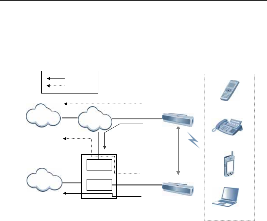
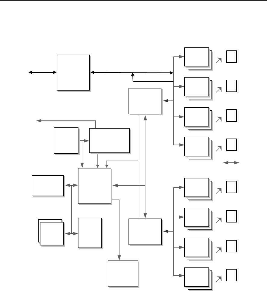
Review the configuration diagram of OfficeServ 500 System below and understand
the equipment implementing the wireless LAN functions and their operational
principles.
Figure 1.1 Configuration Diagram of OfficeServ 500 Wireless LAN
3.1 OfficeServ 500
System
3.1.1 Overview
The OfficeServ 500 System is the primary device of phone that provides the wireless
LAN service.
With the application of the most advanced technologies like VoIP and LAN, the
OfficeServ 500 can connect various multimedia devices in offices where Internet is
actively used. The OfficeServ 500 is the up-to-date digital exchange system that can
be also used as the phone system or PABX system.
The OfficeServ 500 System can be composed of two types, OfficeServ-M and
OfficeServ-L, depending on the scalable line capacity and provided functions. The
OfficeServ-M supports a maximum of 192 lines, and the OfficeServ 500-L can be
scaled up even a maximum of 500 lines.
The OfficeServ 500 System introduced the VoIP(Voice over Internet Protocol)
technology, recently becoming popular, so that the system can provide an Internet
phone service through the IP network(Internet) without additional pieces of
equipment The Internet phone service allows users to have long distance calls and
international calls with only local call charge.
Ethernet 10/100BASE-T
IEEE802.11b
IDCS500 Key Telephone System
WBS24(Basic)
WBS24(Combo)
Voice signal
Data signal
Data signal
LAN
Data signal
Handover
Voice si
g
nal
Voice si
g
nal
MGI
WLI
Internet
PSTN
WIP-5000M
Wireless VoIP
p
hone
PDA
Note
ISDN(4B+D)
like proprietary interface

OfficeServ 500 Wireless LAN Service Manual/Ed.00 CHAPTER 3. Installation
© SAMSUNG Electronics Co., Ltd. Page 1-5
Also, if the 10 M/100 Mbps LAN port, which is provided by the OfficeServ 500
System, is used, the application program like the PCMMC(PC for programming)
uses can be used while connected to Ethernet.
The OfficeServ 500 System supports the Q-Sig networking function that performs
call transfer, DND(Do Not Disturb), CCBS(Call Completion to Busy Subscriber),
and CCNR(Call Completion on No Reply) between the OfficeServ 500 systems,
regardless of the physical location of the system.
Since both hardware and software in the OfficeServ 500 System are designed with
module-based method, upon the need of users, the main line or subscriber’s line can
be easily scaled up or a new software can be installed to add new functions even
during the operation.
Connecting various terminals and additional equipment, the OfficeServ 500 System
can make an integrated environment that provides effective and various services for
wireless LAN users to keep pace with the high speed network and digitalized office
environment.
3.1.2 Major Functions
The major functions of OfficeServ 500 System are described as follows :
Application of New Technology
The OfficeServ 500 System uses the following new technologies to upgrade the
digital exchange system.
Support for VoIP (Voice over Internet Protocol)
10M/100Mbps LAN Port is provided.
Q-Sig networking is supported.
Various kinds of highly integrated card(ITM3, MGI1/2, and TEPRI card)
Powerful system diagnostic/management program is provided.
New key set(DS Series, IP Phone, and Wide LCD) is supported.
The functions of wireless voice and data using the wireless LAN are provided.
Compatibility with the existing system
At the cabinet of OfficeServ 500 System, most cards of existing SKP-180D phone
system can be mounted as they are. Also, the existing terminal can be connected.
Therefore, the cost saving will be great when expanding the capacity and
performance of existing phone system.
Ease of System Installation
Since the OfficeServ 500 System is designed with module-based method, hardware
or software, such as card or cabinet, can be easily added. To the universal slot of
cabinet, any cards can be mounted, such as the main card or extension card, the ISDN
card and other cards providing premium services.

CHAPTER 1.Overview OfficeServ 500 Wireless LAN Service Manual/Ed.00
Page 1-6 © SAMSUNG Electronics Co., Ltd.
The system programming can be done with the system-connected terminal or PC.
Also, the system configuration can be changed easily according to the user’s
requirements.
Ease of System Scalability
If the OfficeServ 500 System is used, there is no need to put in much effort and
expenses to add new functions.
For the OfficeServ -L System case, a maximum of 3 cabinets can be scaled up.
For the 8DLI card, a single line can be scaled up by mounting KDB-S or KDB-D on
the digital phone, without a separate line.
Convenient Maintenance
In order to maintain and repair the system more conveniently, the following functions
are provided.
Programming PC(PCMMC)
− The programming PC is used for maintaining and repairing the OfficeServ
500 System. If the programming PC is used, various types of information
at the system can be inquired or controlled using the program menu.
DPAP-MNA
− The DPAP-MNA is an application software solution that can remotely
manage the OfficeServ 500 System. The DPAP-MNA provides many
functions, such as site management(new registration, modification,
deletion and print), indication of events received from the OfficeServ 500
System, troubleshooting of system problems, program uploading using FTP, and
output of traffic information.
The installing and programming methods of DCS 500 System
Refer to ‘OfficeServ Installation Manual’ and ‘OfficeServ 500 Programming Manual’
for the installing and programming methods of OfficeServ 500 System, the main
component.

OfficeServ 500 Wireless LAN Service Manual/Ed.00 CHAPTER 3. Installation
© SAMSUNG Electronics Co., Ltd. Page 1-7
3.2 8WLI
3.2.1 Overview
The 8WLI card, a service board providing the wireless solution to the OfficeServ 500
System, provides the wired interface in between the OfficeServ 500 System and
WBS24(WLAN Base Station 2.4 GHz), which is the wireless LAN’s AP(Access
Point).
The wired interface method, a digital method, uses 2B+1D DASL(Digital Adapter
Subscriber Loops), and communicates with the upper main CPU board using the
DPRAM(Dual Ports RAM) interface of the IPC(Inter Processor Channel) for
transmitting/receiving messages.
A maximum of one 8WLI card can be mounted on the OfficeServ 500 System, and
the 8WLI can interoperate with a maximum of 8 WBS24s. Since two DASL lines are
connected to one WBS24, simultaneous phone calls are possible through 4 voice
channels of 2 x(2B+1D). Therefore, one 8WLI board can support a maximum of 32
voice channels.
The WBS24 is supplied of –48 V DC power through the DASL line, and can
transmit/receive voice and signaling data in between the 8WLI and WBS24.
3.2.2 Major Functions
The major functions of 8WLI card are as follows :
Provides the wired interface between the AP(Access Point) and the system to
transmit/receive voice and signaling data.
Supports 32 voice channels for each card.
Either provides or blocks -48V DC power supply to the WBS24.
Performs the initiation for the VoIP over WLAN service.
Manages information on all terminals for voice service and provides the service
to only authorized terminal.
Provides the initial registration service for wireless IP-Phone(WIP-5000M).
Provides the calling service to a terminal for voice service.
Supports the mobility between access points, as well as the handover function
for a terminal for voice service.
Interfaces with the main CPU board of OfficeServ 500 System.
CHAPTER 1.Overview OfficeServ 500 Wireless LAN Service Manual/Ed.00
Page 1-8 © SAMSUNG Electronics Co., Ltd.
3.2.3 8WLI Block
Introduces the block diagram of 8WLI card and the functions of each block.
Figure 1.2 8WLI Block Diagram
FWR CTL.
DASL
DASL
DASL
DASL
DASL
DASL
DASL
DASL
DMC0
STL7052E
FWR CTL.
FWR CTL.
FWR CTL.
Signalling
Data Comm.
(16Kbps)
LINE
INTERFACE
FWR CTL.
DASL
DASL
DASL
DASL
DASL
DASL
DASL
DASL
DMC1
STL7052E
FWR CTL.
FWR CTL.
FWR CTL.
Signalling
Data Comm.
(16Kbps)
CPU
MC68302
SIO
RS-232C
Flash
ROM.
512KB
SRAM
512K
Words
SRAM
512KB
DPRAM
CY7C631
CPLD
EPM7064
Clock
Generato
r
OSC
16,384
TCXO
DJT.
10m
600m
DJT, DASL, DEK, DTK
//A1~23
UART
19200bps
SF_DTAC
32Ch,
Echo
Canceller
(ZL50232)
HWx/HW
R
HWx/HW
R

OfficeServ 500 Wireless LAN Service Manual/Ed.00 CHAPTER 3. Installation
© SAMSUNG Electronics Co., Ltd. Page 1-9
Main Processor
The main CPU used in the 8WLI is Motorola’s MC68000/MC68008 core series,
which enhanced the communication function.
The major specification of CPU is as follows :
Supports the interrupt mode(Normal/Dedicated mode)
Supports On-Chip 1152 byte Dual Port RAM
Supports 3 timers
Supports the selection of 4 programmable chips
Supports 3 SCCs(Serial Communication Controllers)
Supports various protocols
Supports various physical interfaces
The CPU is the central control part that leads the performance of programs in the
board, and basically controls the memory and main components for performing the
program. The clock used for the program performance is the oscillator with
16.384MHz frequency, and transmits/receives 16bits data operating with the memory.
The interrupts are handled using the dedicated modes, and their uses are described in
the table below.
Table 1.1 Interrupt Information on 8WLI CPU
Level() Name Remarks
NMI(7) ABORT For debugger
INT(6) DASL INT 16×DASL
INT(4) DMC RX0 PB11(4×DASL)
INT(4) DMC RX1 PB10(4×DASL)
INT(4) 10m sec TIMMER1
INT(4) SIO SCC3
INT(4) INT TX0 PB9(4×DASL)
INT(4) INT TX1 PB8(4×DASL)
INT(1)
Since several interrupts data are
multiplexed onto level4, the processing of
DMC RX and TX interrupts may get
affected.
To prevent this, 10ms interrupt is lowered
to level3 by S/W while performed routinely.
So, even during the 10m sec interrupt
performance, the DMC UART interrupt can
be processed.
Flash Memory
The OfficeServ 500 System uses the flash memory of 512Kword capacity.
The AM29F800B of AMD is used, and this operates with the CPU on the 16 bits
mode for transmitting/receiving data.
In the flash memory, the programs for the 8WLI to perform the relevant functions,
including a booting program, are saved. When the program is changed, the program
can be upgraded using SIO(Serial Input Output) through the UART.

CHAPTER 1.Overview OfficeServ 500 Wireless LAN Service Manual/Ed.00
Page 1-10 © SAMSUNG Electronics Co., Ltd.
SRAM
Two SRAMs of 256 Kbyte X 2 capacity are used, and they operate with the CPU on
the 16 bits mode for transmitting/receiving data. The KM684000LT of SAMSUNG is
used.
Asynchronous Dual Port RAM
The DPRAM is used for data transmission with the main board of OfficeServ 500
system.
The components used for IPC(Inter-processor communication) are the CY7C136-
55NC of Cypress, and this can read/write 2Kbyte data at the same time.
DMC (Digital Module Control)
The 8WLI has 16 DASL links. To control these, one DMC chip is used for 8 DASLs.
Therefore, a total of 2 DMC components are used, and the used components are
STL7052E SAMSUNG ASIC. They can handle interrupts and process data channel
transmission. The major functions are described as follows :
The DMC buffers serial data from 8 DASL transmission chips and transferred to
the CPU, and serially transfers the transmission data from the CPU to each
DASL.
The DMC muxes the interrupts occurred at the initial activation of DASL to send
one source to the CPU, and saves the event changes for each DASL transmission
chip.
The DMC assigns highway timeslot for each DASL chip to be able to program.
DASL (Digital Adapter Subscriber Loops)
The wired interface between the 8WLI and AP(WBS24) uses the DASL components
of NS. One DASL link has the transmission speed at 144kbps, and there are 2B+1D 2
voice channels and one data channel. Since two DASLs for each WBS24 are used,
there are 4B+2D, 4 voice channels and 2 data channels. However, only one data
channel from 2 data channels are used, leaving the one at rest. Also, the transmission
speed of data channel is set at 16 kbps.
The DASL link is connected to two wired cables, so each AP(WBS24) is connected
to 4 wired cables. The 24AWG UPT(Unshielded Twisted Pair wire) cable is used,
and the maximum extension distance is 600M.
Echo Canceller (ZL50232)
Impedance might be mismatched or line echo might occur due to delay during data
processing in the hybrid system. To remove the echo, add the Echo Canceller in the
voice path. The default of the echo tail(echo length) is 64 ms and the echo tail can be
expanded to 128 ms.

OfficeServ 500 Wireless LAN Service Manual/Ed.00 CHAPTER 3. Installation
© SAMSUNG Electronics Co., Ltd. Page 1-11
Power Supply
The power of WBS24 is supplied from the system using the remote power feeding
method. So, -48V DC power of the system is supplied from the 8WLI to the WBS24
through the DASL transmission line. The transmission cable connected between the
WBS24 and the system is composed of 4 strands grouped into 2 pairs. The ground
polarity is supplied to one pair(2 strands), and to the other pair(2 strands), -48 V
voltage DC power is supplied. The maximum wire distance that power can be
supplied is 600M, in case of 24AWG UTP(Unshielded Twisted Pair wire) cable.
3.3 WBS24 (Combo)
3.3.1 Overview
The WBS24(Combo) is the AP(Access Point) for using the wireless LAN service.
AP(Access Point)
AP(Access Point), one of the wireless LAN devices, connects the wired LAN to the
wireless LAN. AP is usually a stand-alone device, which can be used by plugging into
Ethernet hub or a server. One AP hands off to another AP depending on the location
of a user, just like cellular phone does. Therefore, a user can use a mobile phone
while moving around.
3.3.2 Major Functions
The major functions of WBS24(Combo) are as follows :
Provides the wireless RF interface that meets IEEE 802.11b, the wireless LAN
standard.
Provides the wired LAN interface that meets IEEE 802.3, the wired LAN
standard.
Provides the wired interface with OfficeServ 500 System whose speed is 144
Kbps and whose channel is 2B+1D.
Provides voice communication through OfficeServ 500 System using a Voice
over WLAN phone.
Provides a wireless data service to data terminals that have the wireless LAN
interface.
Separates the wirelessly received voice and data from each other and transmits
them to OfficeServ 500 System and LAN.(If a voice message(signal) is received,
it is transmitted to OfficeServ 500 System. If a data message(signal) is received,
it is transmitted to LAN.)
Provides the compression and decompression of PCM voice data.

CHAPTER 1.Overview OfficeServ 500 Wireless LAN Service Manual/Ed.00
Page 1-12 © SAMSUNG Electronics Co., Ltd.
3.3.3 Interface
The WBS24(Combo) consists of wire processing part and wireless processing part.
The wire processing part has two wire interfaces : ISDN BRI interface connected to
OfficeServ 500 system and IEEE 802.3 Ethernet connected to LAN. The wireless
processing part has 2.4 GHz frequency bandwidth of wireless LAN, which complies
with the RF interface based on IEEE 802.11b standard.
Wired Interface Interworking with the OfficeServ 500 System
From a wired interface, the ISDN BRI interworks with OfficeServ 500 System. The
ISDN BRI service is implemented using the Digital Adapter Subscriber
Loops(DASL) chip of National Semiconductor Co., Ltd. This is not a standard ISDN
BRI chip, but Samsung uses it own protocols. Its data transmission speed is 144 Kbps
and there are two voice channels and one data channel. The wired section, which
inter-works with OfficeServ 500 System, sends and receives signaling data for voice
data transmission as well as voice communication.
Wired Interface Interworking with LAN
The wired Ethernet interface can access to LAN with the 10/100BASE-T port and
send/receive data via Internet, other than voice. The wireless processing part can
send/receive voice data for wireless voice communication, as well as data for
wireless access to Internet. The maximum data transmission speed between wireless
sections is up to 4 to 5 Mbps. One unit of WBS24(Combo) can process simultaneous
calls on 4 channels.
Wireless Interface
The wireless interface uses 2.400 to 2.4835 GHz of wireless frequency bandwidth
and meets the IEEE 802.11b standard. Voice can be sent and received across the
wireless sections using a voice-specific terminal. The Voice over WLAN
sends/receives the voice packet data, and laptop computers and PDA send/receive the
data packet across the wireless sections. 13 wireless channels are used in Korea and
11 wireless channels are used in the U.S.
The wireless interface occupies 22 MHz of bandwidth per wireless channel and the
interval between center frequencies is 5 MHz. Therefore, to be a clear channel that
does not interfere with other wireless channels, it should be 4 channels away from
other channels. The wireless processing part sends/receives voice data for wireless
voice communication, as well as data for wireless access to Internet. The maximum
data transmission speed between wireless sections is up to 4 to 5 Mbps. One unit of
WBS24(Combo) can process simultaneous calls on 4 channels.

OfficeServ 500 Wireless LAN Service Manual/Ed.00 CHAPTER 3. Installation
© SAMSUNG Electronics Co., Ltd. Page 1-13
3.3.4 Application Specifications
The WBS24(Combo) is designed to meet both specifications of wireless type and
electromagnetic compatibility(EMC) as follows :
Type Registration (Domestic Specification)
Among different types of wireless equipment that use radio wave signals, the
following equipment, available to the general public, shall be approved of its type.
The following tests shall be conducted according to the standards of ‘Specific Output
Wireless Equipment for Wireless LAN’.
1) The absolute gain of sending antenna shall be less than 6 dBi. However, the
stationary point-to-point wireless equipment shall be less than 20 dBi.
2) Frequency tolerance shall be less than ±50×0-6.
3) The power density supplied to the feeder of sending antenna shall be less than
10mW when it is measured based on 1 MHz of resolution bandwidth.
4) The occupied frequency bandwidth shall be less than 26 MHz
Registration of Electromagnetic Compatibility (Domestic Specification)
The wireless equipment to be homologated(or registered) for electromagnetic
compatibility shall have the following requirements :
1) Input, output, save, search, transmit or control functions for data and
communication messages
2) Have one or more terminal port that operates as for information only
3) Have less than 600 volts of voltage supply
As for information equipment to be homologated, the registration of
electromagnetic compatibility will not be authorized separately, but it will be
processed together with the type registration. Therefore, a test transcript for
electromagnetic compatibility should be submitted when applying for
homologation(for office appliances).
CHAPTER 1.Overview OfficeServ 500 Wireless LAN Service Manual/Ed.00
Page 1-14 © SAMSUNG Electronics Co., Ltd.
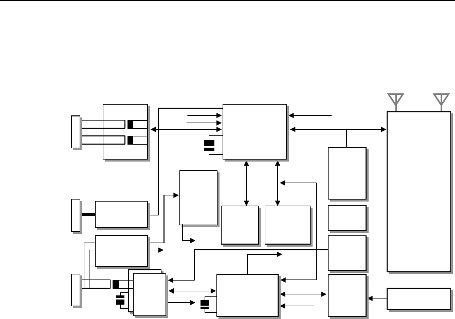
3.3.5 WBS24 (Combo) Block
The block diagram of WBS24(Combo) and functions for each block are as follows.
Figure 1.3 Block Diagram of WBS24 WBS24 (Combo)
3.4 WBS24 (Basic)
3.4.1 Overview
The WBS24(Basic) is the AP(Access Point) for using the wireless LAN service.
3.4.2 Major Functions
The major functions of WBS24(Basic) are as follows :
Provides the wireless RF interface that meets IEEE 802.11b, the wireless LAN
standard.
Provides the wired LAN interface that meets IEEE 802.3, the wired LAN
standard.
Provides voice communication through OfficeServ 500 System using a Voice
over WLAN phone.
Provides a wireless data service to data terminals that have the wireless LAN
interface.
Separates the wirelessly received voice and data from each other and transmits
them to OfficeServ 500 System and LAN.(If a voice message(signal) is received,
it is transmitted to OfficeServ 500 System. If a data message(signal) is received,
it is transmitted to LAN.)
Provides the compression and decompression of PCM voice data.
Magnetic Embedded
CPU
(NetARM
Core *2)
PCMCIA
Power
Controller
(3.3V/5V Auto
Switch
)
LED
Control
UART
Controller
SRAM
64K word Reset Control
WLAN NIC
CARD
(802.11b)
MAC/BB/Ext.
Ant.
External
A
ntenna
- Diversity
- Gain : 2dBi
- Dipole
Flash ROM
4M byte
SDRAM
16M byte
Voltage
Regular
Input : 3.3V
Output : 1.8V
SIO
RS232C
DC/DC Power
(Remote)
-48/+5, +3.3
DASL
DSP
- Audio Codec
- Echo Cancellation
RJ-45
RJ-45
RJ-45
Ethernet
10/100T
UART
DASL_Int.
Reset
Ethernet I/F
25MHz Xtal
SDRAM
BUS
32bits
EPB BUS
8bits
DSP_Int(To Host)
1.8V
3.3V
5.0V UART
(D_Ch)
PCM I/F
DASL.Int
2048NHz
OSC
20MHz Xtal
Reset
BUS 16bits
HPI 8bits
Reset
DSP_Int
PCMCIA I/F(EPD)
3.3V or 5.0V
-48V

OfficeServ 500 Wireless LAN Service Manual/Ed.00 CHAPTER 3. Installation
© SAMSUNG Electronics Co., Ltd. Page 1-15
3.4.3 Interface
The WBS24(Basic) consists of wire processing part and wireless processing part.
The wire processing part has a wire interfaces : IEEE 802.3 Ethernet connected to
LAN. The wireless processing part has 2.4 GHz frequency bandwidth of wireless
LAN, which complies with the RF interface based on IEEE 802.11b standard.
Wired Interface Interworking with LAN
The wired Ethernet interface can access to LAN with the 10/100BASE-T port and
send/receive data via Internet, other than voice. The wireless processing part can
send/receive voice data for wireless voice communication, as well as data for
wireless access to Internet. The maximum data transmission speed between wireless
sections is up to 4 to 5 Mbps. One unit of WBS24(Basic) can process simultaneous
calls on 4 channels.
Wireless Interface
The wireless interface uses 2.400 to 2.4835 GHz of wireless frequency bandwidth
and meets the IEEE 802.11 b standard. Voice can be sent and received across the
wireless sections using a voice-specific terminal. The Voice over WLAN
sends/receives the voice packet data, and laptop computers and PDA send/receive the
data packet across the wireless sections. 13 wireless channels are used in Korea and
11 wireless channels are used in the U.S.
The wireless interface occupies 22 MHz of bandwidth per wireless channel and the
interval between center frequencies is 5 MHz. Therefore, to be a clear channel that
does not interfere with other wireless channels, it should be 4 channels away from
other channels. The wireless processing part sends/receives voice data for wireless
voice communication, as well as data for wireless access to Internet. The maximum
data transmission speed between wireless sections is up to 4 to 5 Mbps. One unit of
WBS24(Basic) can process simultaneous calls on 4 channels.
3.4.4 Application Specifications
The WBS24(Basic) is designed to meet both specifications of wireless type and
electromagnetic compatibility(EMC) as follows :
Type Registration (Domestic Specification)
Among different types of wireless equipment that use radio wave signals, the
following equipment, available to the general public, shall be approved of its type.
The following tests shall be conducted according to the standards of ‘Specific Output
Wireless Equipment for Wireless LAN’.
1) The absolute gain of sending antenna shall be less than 6 dBi. However, the
stationary point-to-point wireless equipment shall be less than 20 dBi.
2) Frequency tolerance shall be less than ±50×0-6.

CHAPTER 1.Overview OfficeServ 500 Wireless LAN Service Manual/Ed.00
Page 1-16 © SAMSUNG Electronics Co., Ltd.
3) The power density supplied to the feeder of sending antenna shall be less than
10mW when it is measured based on 1 MHz of resolution bandwidth.
4) The occupied frequency bandwidth shall be less than 26 MHz
Registration of Electromagnetic Compatibility (Domestic Specification)
The wireless equipment to be homologated(or registered) for electromagnetic
compatibility shall have the following requirements :
1) Input, output, save, search, transmit or control functions for data and
communication messages
2) Have one or more terminal port that operates as for information only
3) Have less than 600 volts of voltage supply
As for information equipment to be homologated, the registration of electromagnetic
compatibility will not be authorized separately, but it will be processed together with
the type registration. Therefore, a test transcript for electromagnetic compatibility
should be submitted when applying for homologation(for office appliances).
OfficeServ 500 Wireless LAN Service Manual/Ed.00 CHAPTER 3. Installation
© SAMSUNG Electronics Co., Ltd. Page 1-17
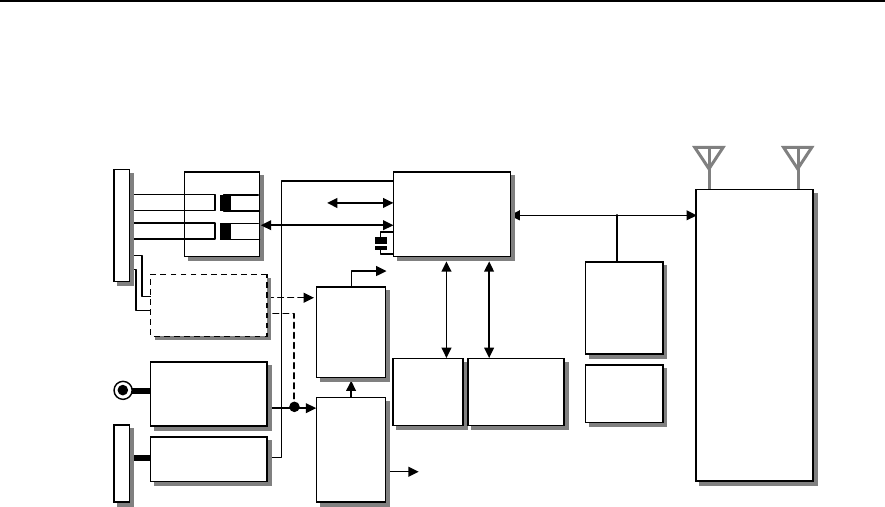
3.4.5 WBS24 (Basic) Block
The block diagram of WBS24(Basic) and functions for each block are as follows.
Figure 1.4 Block Diagram of WBS24 WBS24 (Basic)
3.5 WIP-5000M
3.5.1 Overview
The WIP-5000M(Wireless IP-Phone Mobile type) is the wireless mobile phone that
allows a voice communication through IEEE 802.11b wireless LAN. As the wireless
IP phone, the voice data is compressed into a packet form(Voice over WLAN) to
satisfy the wireless LAN specifications and the data is transferred/received through IP
network. When moving between Access Points(WBS24), as well as between the data
terminals like laptop computers with wireless LAN card, the handover function is
supplied. The major functions of WIP-5000M are described as follows :
Supports the wireless LAN specification of IEEE802.11b.
Supports the SIP protocols in order to support the VoIP.
Supports various voice codecs.(G.711, G.726, G.723, and G.729)
Provides the echo suppression function.
Supports the display service of incoming VMS-messages(Voice Mailing System).
Supports the message service provided from the phone of OfficeServ 500
System.
The system upgrade can be done through the wireless LAN.
Laptop computers, PDA and IP Phone, except the WIP-5000M, can use general-
purpose equipment.
WLAN NIC
CARD
(802.11b)
MAC/BB/Ext.
Ant.
External
A
ntenna
- Diversity
- Gain : 2dBi
- Dipole
PCMCIA
Power
Controller
(3.3V/5V Auto
Switch
)
LED
Control
Embedded
CPU
(NetARM Core *2)
Flash ROM
4M byte
SDRAM
16M byte
Voltage
Regular
Input : 3.3V
Output : 1.8V
Voltage
Regular
Input : 5V
Output : 3V
AC/DC Adaptor
(Local Power)
AC220/DC+5V
SIO
RS232C
DC/DC Power
(Remote)
-48/+5, +3.3
25MHz Xta
Reset
Ethernet I/F
Ethernet
10/100T
RJ-45
-48V 3.3V
5.0V
1.8V SDRAM
BUS
32bits
PCMCIA I/F(EPD)
3.3V or 5.0V
3.3V
Magnetic
CHAPTER 1.Overview OfficeServ 500 Wireless LAN Service Manual/Ed.00
Page 1-18 © SAMSUNG Electronics Co., Ltd.
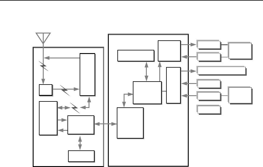
3.5.2 WIP-5000M Block Diagram
Figure 1.5 Block Diagram of WIP-5000M
The WIP-5000M is largely divided into 3 parts as below :
Wireless LAN Part
The wireless method used for the WIP-5000M is the IEEE802.11b Wireless LAN
specification at the 2.4GHzbandwith.
Also, the major components of wireless LAN are the Prism2.5 of Intersil, and are
composed of 4 components, such as ISL3984(PA), HFA3783(IF I/Q MOD. DEMOD.),
ISL3685, and MAC/BBP ISL3873B.
CPU, VoIP (SIP) Part
The CPU used for the WIP-5000M is a combined type that the RISC and DSP
functions are combined into one processor. That is, there is no need for a separate
DSP when processing voice for the Voice over WLAN. Also, the internal SRAM
allows the program performance possible without a separate external memory.
The major functions for the main processor are summarized as the wireless LAN,
control of other major components, processing of voice codecs, and echo removal.
The user interface part
The user interface part can provide various and convenient functions using graphic
LCDs and navigation key.
BPF
PA
IF/
MOD BBP
MAC
RF/IF
Conv
F/ROM
PCMCIA
CPLD
MPU
Netergy
Flash MEM
CODEC
MMI
INTERFACE
Receiver
MIC
Graphic LCD
Key-pad
Battery
Vibrato
r
Charging
Cradle
Head
Set
WLAN(802.11b) Part CPU, VoIP(SIP) Part User Interface Part

OfficeServ 500 Wireless LAN Service Manual/Ed.00 CHAPTER 3. Installation
© SAMSUNG Electronics Co., Ltd. Page 1-19
4 Specification of OfficeServ 500
Wireless LAN
This section introduces the relevant specifications of OfficeServ 500 Wireless LAN.
4.1 Specification of Wireless LAN
Table 1.2 General Specification of Wireless LAN
Category Specification
Primary Device OfficeServ 500
Number of mountable 8WLI Card 1 8WLI/ OfficeServ 500
Number of AP(WBS24(Combo)) 8 WBS24(Combo)/8WLI
Number of Subscribers 48 user/8WLI
Scope of transmission throughput 50M in house(may vary depending on the frequency jamming
material in the office)
200M outside the building(No frequency jamming material
within the line of sight distance)
Extended Distance of wiring Maximum of 600M
32 call/8WLI Number of voice channels that allow
simultaneous phone conversations. 4 call/WBS24(Combo)
4.2 Specification of WBS24 (Combo/Basic)
Table 1.3 Specification of WBS24 (Combo/Basic)
Category Specification
Standard of Interface Specification WLAN : 802.11b
VoIP : SIP Protocol
RF frequency 2.412~2.462 GHz
RF Output Power(EIRP) Maximum of 18dBm
Cell Implementation 3 clear channel
Ethernet 10/100BASE-T
Voice Codec G.711/G729A/G726
Size 328(width) x 80(length) x 41(height) mm
Weight About 1kg
Power WBS24(Combo) : -48 V(supplied from the system)
WBS24(Basic) : AC/DC Adaptor(220V/5 V)
Antenna 2 External Antenna Diversity
LED Power, Voice1, Voice2, Link, Data, Wireless
External Connector External power jack, RJ45 LAN, RJ45 API, RJ45 SIO, and
PCMCIA slots
CHAPTER 1.Overview OfficeServ 500 Wireless LAN Service Manual/Ed.00
Page 1-20 © SAMSUNG Electronics Co., Ltd.
4.3 Specification of WIP-5000M
Table 1.4 Specification of WIP-5000M
Category Specification
Standard Interface Specification WLAN : 802.11b, VoIP : SIP Protocol
RF frequency 2.412~2.462 GHz
RF output power(EIRP) Maximum of 13dBm
Transmission Protocols DSSS(Direct Sequence Spread Spectrum)
Voice Codec G711/G729A/G723.1
Size 125(width)x45(length)x24(height) mm
Weight About 95g
Battery 3.8V Li-Ion /800 mA
Conversation Time(Call Duration) 2.5 hour
Call Waiting Time 25 hour
LCD : the line indicating 8 icons,
4 character input lines
Key pad
External battery charger
Composition
Antenna : Super sensitive antenna
The OfficeServ 500 System specification
Refer to ‘OfficeServ 500 Installation Manual’ for the OfficeServ 500 system
specification.
CHAPTER 2
© SAMSUNG Electronics Co., Ltd. Page 2-1
Hardware of OfficeServ 500
This chapter examines the 8WLI card that provides the wireless LAN function of
OfficeServ 500 the WBS24(Combo), WBS24(Basic)and the front/back sides of WIP-
5000M. Also, this chapter describes how to use each port and how to check the status
of equipment through the LED indicators.
1 8WLI
The 8WLI(Wireless LAN Interface) card shall be mounted on the OfficeServ 500
System, and this card is loaded with the wireless LAN function.
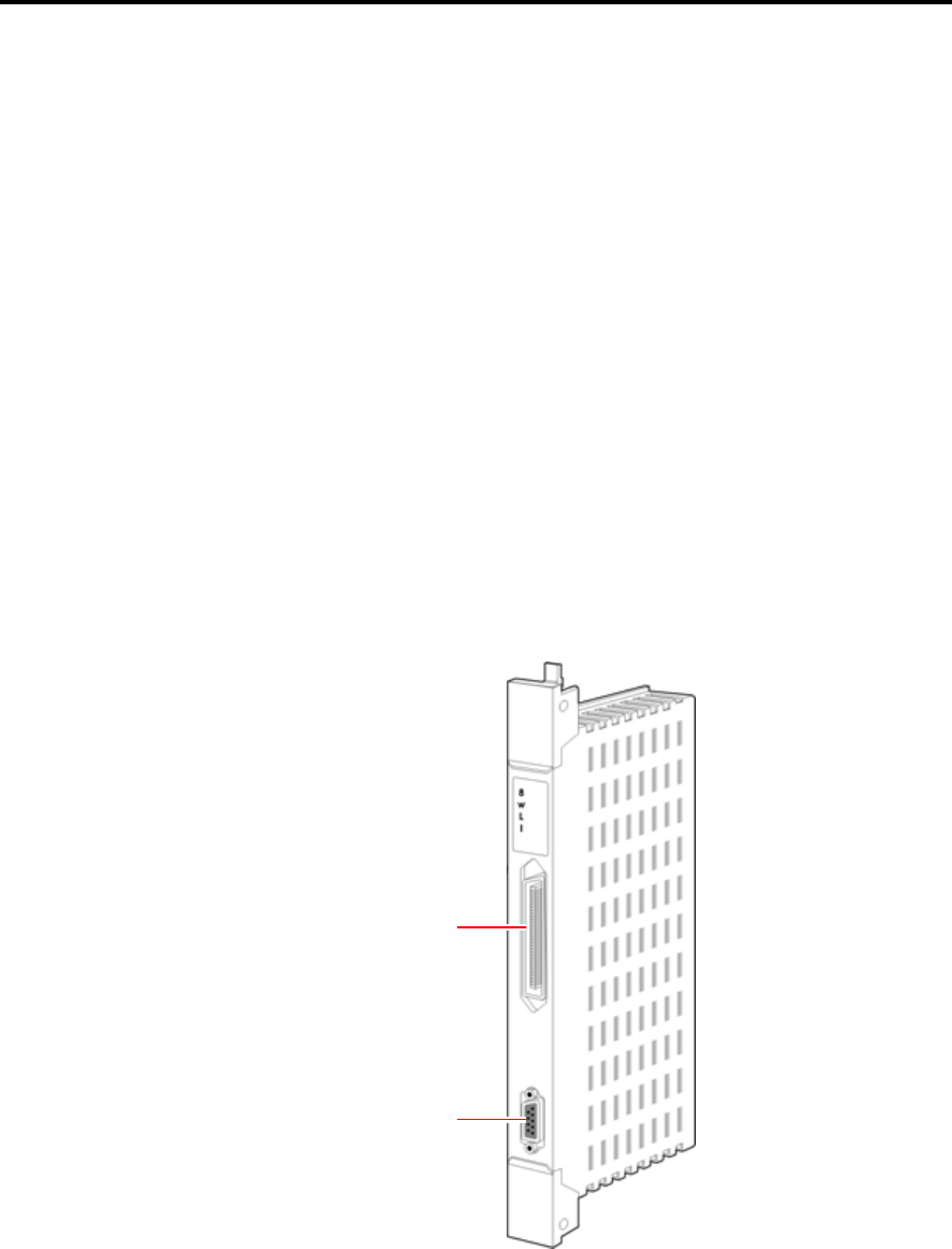
Front Side
The front of 8WLI card is shown below.
Figure 2.1 Front side of 8WLI Card
Champ connector
RS-232 connector
CHAPTER 2. Hardware of OfficeServ 500 OfficeServ 500 Wireless LAN Service Manual/Ed.00
Page 2-2 © SAMSUNG Electronics Co., Ltd.
Champ Connector
Composed of 50 pins. This champ connector is used for connecting the WBS24.
RS-232C Connector
Composed of 9 pins. This connector is used for connecting the console terminal to
download the software of 8WLI card.
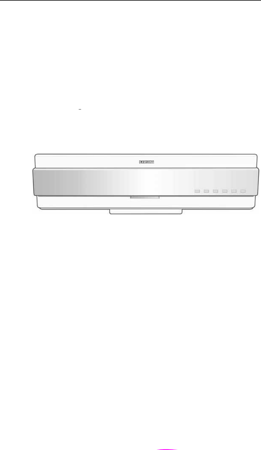
2 WBS24 (Combo)
The WBS24(ComboU)U is the AP for using the 2.4GHz wireless LAN service.
Front Side
The front side of WBS24(Combo) is shown below.
Figure 2.2 Front side of WBS24 (Combo)
WLAN LAN WLI LD1 LD2 PWR
OfficeServ 500 Wireless LAN Service Manual/Ed.00 CHAPTER 2. Hardware of OfficeServ 500
© SAMSUNG Electronics Co., Ltd. Page 2-3
LED
The LEDs are placed on the front side of WBS24(Combo) to show the status of
WBS24(Combo) equipment. The LED states are described in the following table.
Table 2.1 LED states of WBS24 (Combo)
LED Name Function Blue LED On Blue LED Off Blue LED Blinking
WLAN Wireless LAN is
operating
Wireless LAN is
normally operating
Wireless LAN
is not operating
Data is
transmitted/received
through wireless LAN.
LAN LAN is operating LAN is normally
operating
LAN is
normally not
operating
Data is
transmitted/received
through LAN.
WLI Connected with 8WLI Normally
connected with
8WLI
Not connected
with 8WLI
Data is
transmitted/received
through the 8WLI
card and DASL line.
LD1 Indicating the B
channel in use.
Refer to the Table below.
LD2 Indicating the B
channel in use.
Refer to the Table below.
PWR Power is on Power is normally
supplied.
Power is not
normally
supplied.
-
Table 2.2 LD1 and LD2 states of WBS24 (Combo)
B channel No. on busy States of LD1 States of LD2
0 Blue LED Off Blue LED Off
1 Blue LED blinking periodically Blue LED Off
2 Blue LED On Blue LED Off
3 Blue LED On Blue LED blinking periodically
4 Blue LED On Blue LED On
The status of WBS24(Combo)
Refer to ‘Chapter 5 Maintenance’ of this manual for how to inquire the status of
WBS24(Combo) through the LEDs in detail.
CHAPTER 2. Hardware of OfficeServ 500 OfficeServ 500 Wireless LAN Service Manual/Ed.00
Page 2-4 © SAMSUNG Electronics Co., Ltd.
Back Side
The backside of WBS24(Combo) is as shown below.
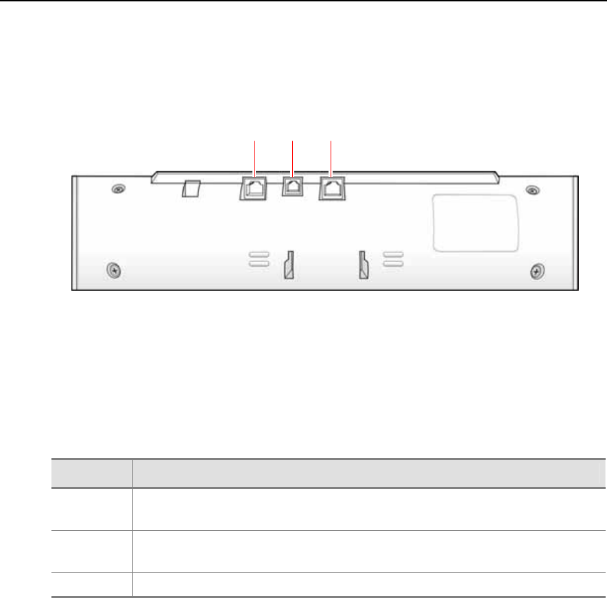
Figure 2.3 Back side of WBS24 (Combo)
Port
The ports on the back of WBS24(Combo) and their functions are described as
follows :
Table 2.3 Functions of WBS24 (Combo) Ports
LED Name Functions
WLI Connecting the RJ-45 connector of twisted pair cable that is connected with the 8WLI
card.
SIO RS-232C type of connecting port used for monitoring the operational status of
WBS24(Combo).
LAN Wired Ethernet port that connects the RJ-45 connector of LAN cable.
WLI SIO LAN
OfficeServ 500 Wireless LAN Service Manual/Ed.00 CHAPTER 2. Hardware of OfficeServ 500
© SAMSUNG Electronics Co., Ltd. Page 2-5
3 WBS24 (Basic)
The WBS24(Basic) is the AP for using the 2.4GHz wireless LAN service.
Front Side
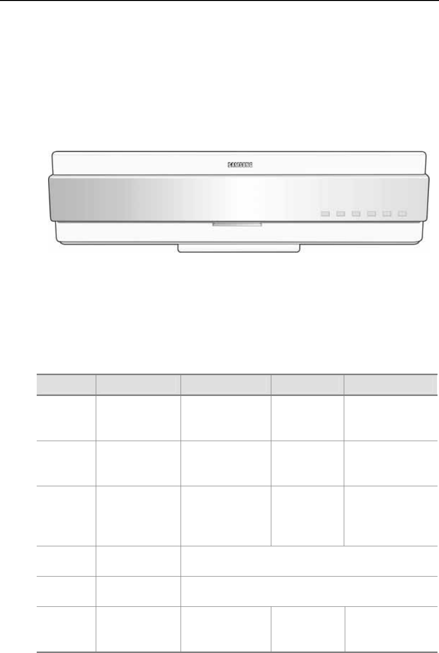
The front side of WBS24(Basic) is shown below.
Figure 2.4 Front side of WBS24 (Basic)
LED
The LEDs are placed on the front side of WBS24(Basic) to show the status of
WBS24(Basic) equipment. The LED states are described in the following table.
Table 2.4 LED states of WBS24 (Basic)
LED Name Function Blue LED On Blue LED Off Blue LED Blinking
WLAN Wireless LAN is
operating
Wireless LAN is
normally operating
Wireless LAN is
not operating
Data is
transmitted/received
through wireless LAN.
LAN LAN is operating LAN is normally
operating
LAN is normally
not operating
Data is
transmitted/received
through LAN.
WLI Connected with
8WLI
Normally connected
with 8WLI
Not connected
with 8WLI
Data is
transmitted/received
through the 8WLI
card and DASL line.
LD1 Indicating the B
channel in use.
Refer to the Table 2.2
LD2 Indicating the B
channel in use.
Refer to the Table 2.2
PWR Power is on Power is normally
supplied.
Power is not
normally
supplied.
-
WLAN LAN WLI LD1 LD2 PWR
CHAPTER 2. Hardware of OfficeServ 500 OfficeServ 500 Wireless LAN Service Manual/Ed.00
Page 2-6 © SAMSUNG Electronics Co., Ltd.
Back Side
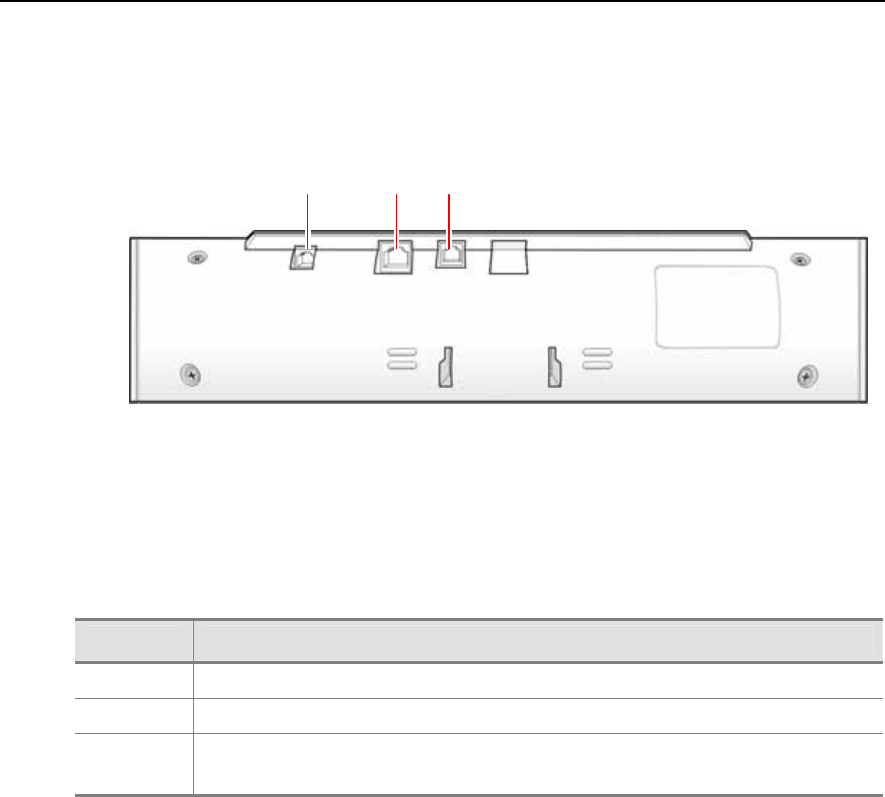
The backside of WBS24(Basic) is as shown below.
Figure 2.5 Back side of WBS24 (Basic)
Port
The ports on the back of WBS24(Basic) and their functions are described as follows :
Table 2.5 Functions of WBS24 (Basic) Ports
LED Name Functions
DC 5 V Used for local power supply. It is a spare part and not used usually.
LAN Wired Ethernet port that connects the RJ-45 connector of LAN cable.
SIO RS-232C type of connecting port used for monitoring the operational status of
WBS24(Basic).
DC IN 5V LAN SIO
○
+ ○
-
CHAPTER 3
© SAMSUNG Electronics Co., Ltd. Page 3-1
Installation
This chapter describes the installation procedure for the wireless LAN device. This
chapter describes procedures for mounting the 8WLI card to the OfficeServ 500
system, mounting the WBS24, setting the system DB for the wireless LAN service,
registering the WIP mobile phone, and positioning the WBS24.
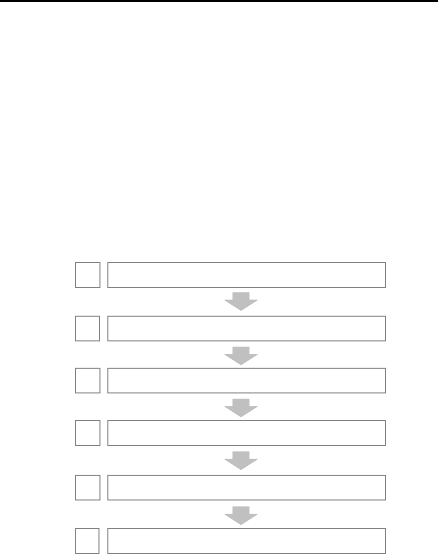
1 Installation Procedure
Installation and configuration procedures for the wireless LAN equipment of
OfficeServ 500 System are as follows.
Figure 3.1 The Wireless LAN Installation Procedure
Mount the 8WLI card on the OfficeServ 500 S
y
stem.
Install the WBS24 within the wireless LAN service area.
Connect the 8WLI with the WBS24 using the RJ-45 cable.
Re
g
ister the WIP-5000M terminal.
Select the location where the WBS24 is to be installed
1
Set u
p
the s
y
stem DB for the wireless LAN.
2
3
4
5
6
CHAPTER 3. Installation OfficeServ 500 Wireless LAN Service Manual/Ed.00
Page 3-2 © SAMSUNG Electronics Co., Ltd.
2 Mounting the 8WLI
Mount the 8WLI following the below instructions.
1) Prepare the 8WLI card.
2) Turn off the power of the OfficeServ 500 System and detach the front cover of
the OfficeServ 500 System using a screwdriver.
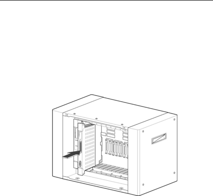
3) Mount the 8WLI card between slot 1 and slot 3 inside the cabinet. There are
guardrails attached at the top and bottom of the slot to fasten the 8WLI card.
Using these guardrails, carefully push the card into the system.
Figure 3.2 Mounting the 8WLI Card (1)
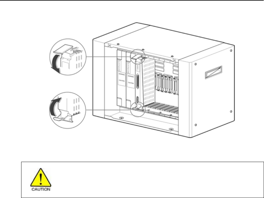
4) Firmly press the center of the card’s front panel to fully insert the 8WLI card into
the main board connector.
5) Once the 8WLI card is fully inserted into the main board connector, lower the
levers at the top and bottom of the slot inwards to fasten the card.
OfficeServ 500 Wireless LAN Service Manual/Ed.00 CHAPTER 3. Installation
© SAMSUNG Electronics Co., Ltd. Page 3-3
Figure 3.3 Mounting the 8WLI Card (2)
Cautions against mounting the 8WLI card
The 8WL card can be installed in the OfficeServ 500 System. Do not use this card on
other systems.

CHAPTER 3. Installation OfficeServ 500 Wireless LAN Service Manual/Ed.00
Page 3-4 © SAMSUNG Electronics Co., Ltd.
3 Mounting the WBS24
The WBS24 is classified into wall WBS24 and desk WBS24 depending on
installation types. This section describes how to install a wall WBS24 or desk
WBS24.
3.1 Wall Type of WBS24
A WBS24 can be installed on the wall to offer the wireless LAN service as described
below :
Required Tools
Prepare the following tools in advance when mounting the WBS24 on a concrete wall.
Electric drill, hammer
Wall bracket
Cross-tip screwdriver(6.5 mm)
Two plastic anchors
Two cross-tip screws
WBS24
Mounting Instruction
1) Attach the <screw position diagram>, which comes with the WBS24, on the wall
where the WBS24 is to be mounted.
The screw position diagram
If the <screw position diagram> is not available, press an A4 paper sheet against the
bottom surface of the WBS24, and mark the two positions of the screw hole.
OfficeServ 500 Wireless LAN Service Manual/Ed.00 CHAPTER 3. Installation
© SAMSUNG Electronics Co., Ltd. Page 3-5
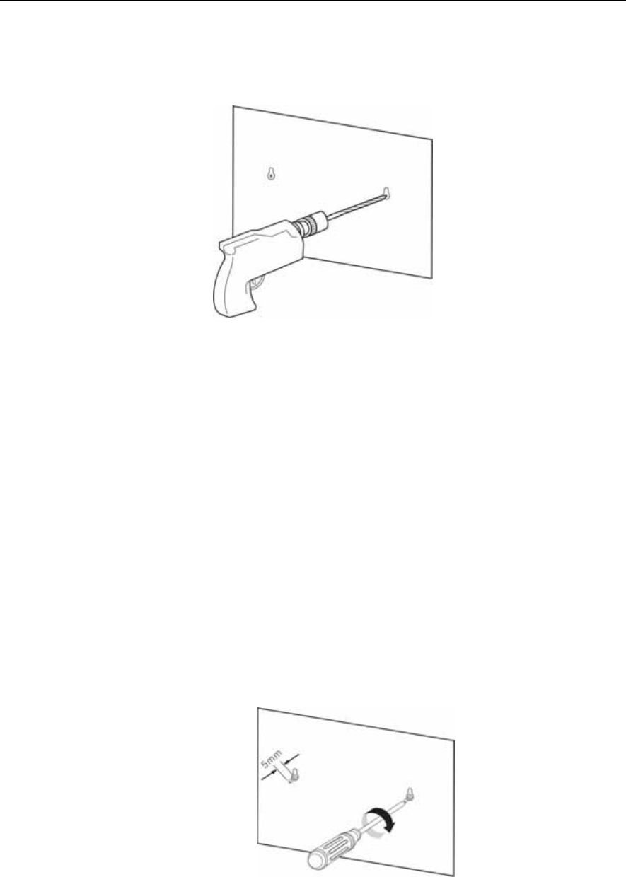
2) Drill a hole at the ‘screw position’ illustrated in the <screw position diagram>.
The hole shall be at least 35mm deep and 5.5mm wide, which will enable the
plastic anchor to enter the hole easily.
Figure 3.4 Mounting the WBS24 on a Concrete Wall-Drilling a Hole
3) Detach the <screw position diagram> after drilling the hole.
4) Insert the plastic anchor into the hole using a hammer.
Figure 3.5 Mounting the WBS24 on a Concrete Wall-Inserting the Plastic Anchor
5) Insert a screw into the plastic anchor and tighten the screw with a cross-tip
screwdriver. Do not fully tighten the screw, but leave a gap of 5mm.
Figure 3.6 Mounting the WBS24 on a Concrete Wall-Tightening the Screw
CHAPTER 3. Installation OfficeServ 500 Wireless LAN Service Manual/Ed.00
Page 3-6 © SAMSUNG Electronics Co., Ltd.
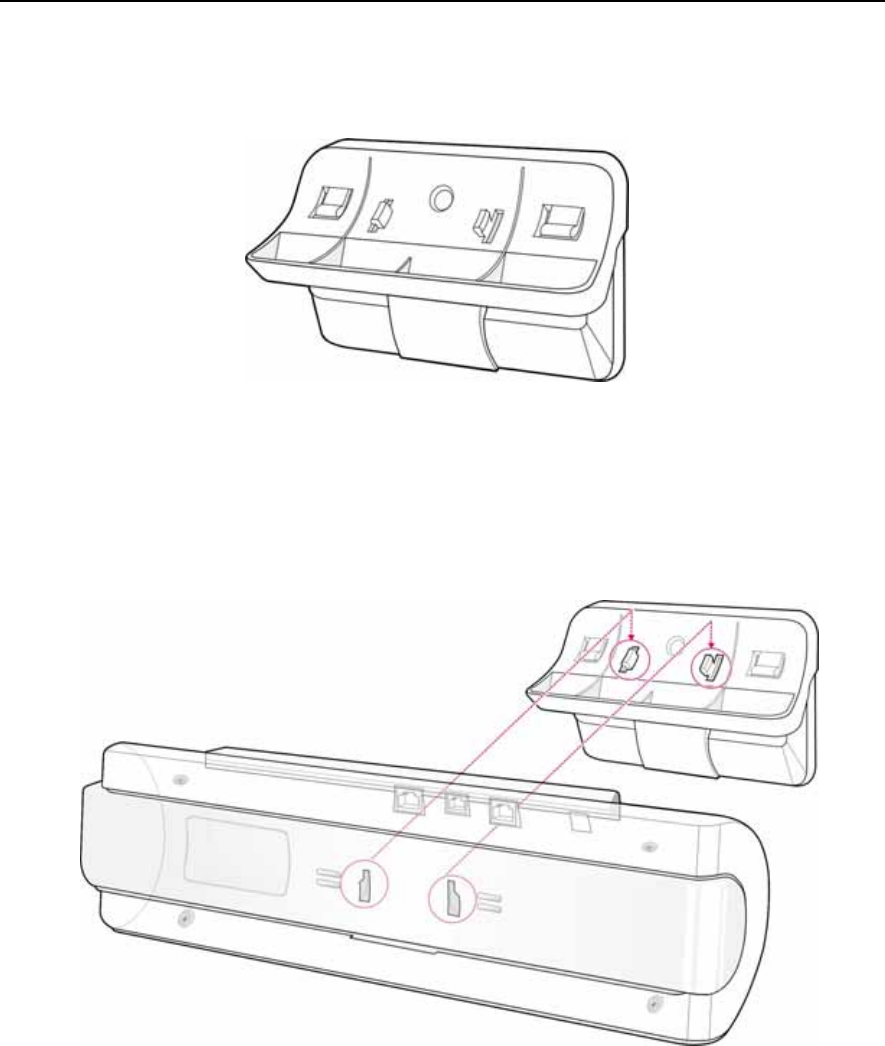
6) Two screw holes exist in the prop of the WBS24 system. Insert the screws on the
wall into the screw holes. Pull the prop downward.
Figure 3.7 Mounting the WBS24 on a Concrete Wall
7) Two holes exist at the bottom surface of the WBS24 system. The holes can be
attached to the prop of the WBS24 system. Fit the WBS24 system with its prop.
Figure 3.8 Mounting the WBS24 on a concrete wall-Attach the WBS24 to its Prop
Prop of the WBS24 System
Rear View of the WBS24 System
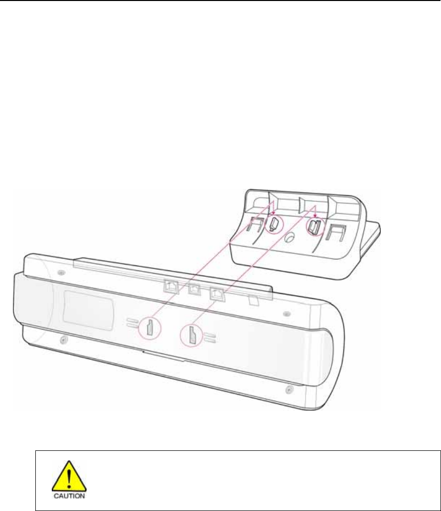
OfficeServ 500 Wireless LAN Service Manual/Ed.00 CHAPTER 3. Installation
© SAMSUNG Electronics Co., Ltd. Page 3-7
3.2 Desk Type of WBS24
The WBS24 can be installed on a desk by attaching its prop to the desk to offer the
wireless LAN service.
Two holes exist at the bottom surface of the WBS24 system.. The holes can be
attached to the prop of the WBS24 system. Fit the WBS24 system with its prop as
shown below : Put the WBS24 system on the desk carefully while preventing the
system from being shaken or falling down.
Figure 3.9 Installing a Desk WBS24
Cautions against installing the desk WBS24
When putting the WBS24 on the desk, do not install the WBS24 at an unstable
location or on a smaller prop than the WBS24 system.
Rear View of the WBS24 System
Prop of the WBS24 System

CHAPTER 3. Installation OfficeServ 500 Wireless LAN Service Manual/Ed.00
Page 3-8 © SAMSUNG Electronics Co., Ltd.
4 Connecting the 8WLI with the WBS24
When the cable with two twisted-pairs connecting the 8WLI and the WBS24 has the
common characteristics, the OfficeServ 500 System’s wireless LAN offers good
performance.
Even when one of the two cable pairs is disconnected, the power will be supplied
normally, since the WBS24 uses the phantom feeding method for power supply.
This section describes the procedure for connecting the 8WLI, which is mounted on
the OfficeServ 500 System, with the WBS24, which is installed on a wall.
Preparing the Cable
Prepare a RJ-45 cable or two twisted-pair(4 wires) cables of the below specifications.
Figure 3.10 RJ-45 cable
Table 3.1 Twisted Pair cable specifications
Item Cable Specifications
Diameter 0.6 mm or 0.4 mm
Length 0.6mm in diameter and 600M or less in length, or 0.4 mm in diameter and
400 M or less in length.
Interface 2×U interface & 64 Kbit/sec via 4 B-channels
8WLI
WBS24
8WLI connector WBS24 connector
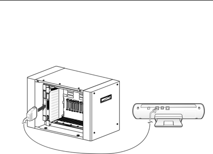
OfficeServ 500 Wireless LAN Service Manual/Ed.00 CHAPTER 3. Installation
© SAMSUNG Electronics Co., Ltd. Page 3-9
Connecting the Cable
Connect the twisted-pair cable following the below instructions.
As shown below, connect the Champ connector of the twisted-pair cable to the
8WLI’s Champ connector, and connect the RJ45 connector to the WBS24’s WLI port.
Figure 3.11 Connecting the WBS24 with the 8WLI card

CHAPTER 3. Installation OfficeServ 500 Wireless LAN Service Manual/Ed.00
Page 3-10 © SAMSUNG Electronics Co., Ltd.
5 Setting the System DB
Before using the WIP-5000M terminal on the OfficeServ 500 System, appropriate
values for the following items must be set in accordance with the operating
environment, using the MMC program.
5.1 Setting the System KEY
System KEY is used internally in the system. System ID KEY is an authentication
parameter used in the user identification procedure when registering a WIP500M
mobile phone to the wireless LAN system. The default value ‘00000’ must be
modified to another value(at most 5 characters long) using the MMC 845 program, to
activate the wireless LAN.
5.2 Setting the System ID
All terminals used in the wireless LAN shall have the System ID set for access.
Scanning of this value is always possible at a general terminal, and this value can be
modified to random characters for system identification when managing the system.
The default value ‘WBS24’ can be modified to another value(at most 6 characters
long) using the MMC 845 program.
5.3 Setting the WBS24
The wireless LAN Access Point, or the WBS24, must be activated to employ the
wireless LAN. For voice service only, enter the SECOND WBS IP of the MMC845,
and use the default values of the WBS24.
However, to offer a wireless data service, the IP Address, Netmask, Gateway, and
DNS, which are effective in the Intranet or Internet network, must be set at the
Network Configuration DB for the WBS24
The default value may be modified to an environment with less interference by
verifying the interference between cells for each WBS24.
Caution when setting the WBS24 Second IP
To use the Internet network, the first three digits of the IP assigned to the WBS24 and
the first three digits of the Second WBS24 IP of the WBS24 must be identical. If the IP
assigned to the WBS24 and the Station is 168.219.149.xxx, then the Second IP of the
WBS24 shall be 168.xxx.xxx.xxx.

OfficeServ 500 Wireless LAN Service Manual/Ed.00 CHAPTER 3. Installation
© SAMSUNG Electronics Co., Ltd. Page 3-11
5.4 Assigning a terminal IP
Before registering a WIP500M terminal, an effective IP address shall be assigned to
the WIP-5000M terminal using the MMC 848 program. This IP address shall be
assigned for each terminal.
Although this IP address may not be relevant when not using the data service, assign
an effective IP address for later use of both voice and data services.
5.5 Authorizing the Terminal Register
A wireless LAN terminal shall be registered at the system DB in order to be used for
the OfficeServ 500 System. After authorizing the terminal register through the MMC
849 program, register the terminal following the registration procedure. The
password used for entering the register authorization menu can be changed through
the MMC 849 program, along with the previous password used for the OfficeServ
500 In addition, the WEP(Wired Equivalent Privacy), an encryption method for the
wireless LAN, is used to maintain data confidentiality in the wireless environment.
Execute the MMC 849 program for authorizing a terminal register in order to register
a terminal to the system. Once the terminal registration is complete, cancel the
register authorization to restrict the registration of other terminals.
MMC Programming
Refer to ‘Chapter 5 MMC Programming’ of this Description for programming procedures
related to the wireless LAN.

CHAPTER 3. Installation OfficeServ 500 Wireless LAN Service Manual/Ed.00
Page 3-12 © SAMSUNG Electronics Co., Ltd.
6 Registering/Clearing the WIP-5000M Terminal
The WIP500M terminal must be registered to the system to be used in the OfficeServ
500 System Wireless LAN. This section introduces the procedures for registering and
clearing the register of a terminal.
6.1 Registering a WIP-5000M
Register a WIP-5000M terminal following the instructions below.
1) Confirm if the system DB items are set according to the ‘Setting the System DB’
section of this chapter.
2) Register the WIP-5000M terminal at the register menu.
Refer to the ‘WIP-5000M User Manual’ for the register procedure.
3) The Network ID shall be entered correctly during the WIP-5000M register
procedure. Especially, the User ID and Password shall be identical to that of the
system. If an error occurs during execution of register procedure, check the
system DB settings and repeat the procedure above.
4) An extension number will be assigned to the WIP-5000M upon completion of
the terminal register.
6.2 Clearing a WIP-5000M
Where theft or breakage of a WIP500M Station causes a new terminal to be
registered, registration of the previous terminal shall be deleted.
The clearing procedure for the WIP-5000M is described below.
Clearing from the System
To clear the WIP500M in use, which is within the wireless LAN service area, set the
normal mode through the system MMC.
If the terminal is not within the service area or is not in use, delete the terminal’s
registration DB in the system using the forced mode through the MMC system.
Clearing from the WIP-5000M
The terminal’s registration DB may be deleted from the WIP500M within the
wireless LAN service area. Refer to the ‘WIP500M User Manual’ for termination
procedure in detail.
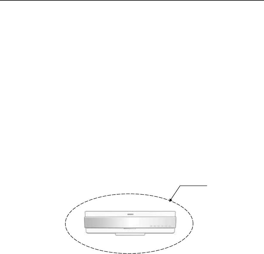
OfficeServ 500 Wireless LAN Service Manual/Ed.00 CHAPTER 3. Installation
© SAMSUNG Electronics Co., Ltd. Page 3-13
7 Positioning the WBS24
This section introduces the cell in where the WBS24 will be installed, and describes
the data transmission rate affected by the terminal’s location.
7.1 Cell Overview
The Figure 3.10 below illustrates the wireless transmission range of the WBS24.
Theoretically, the range of a cell is presented as a circle, but in reality, the shape may
be altered depending on the surrounding environment such as the location of the
WBS24 or the surrounding structures.
The boundary of a cell normally indicates the frequency range of WBS24, but
actually, it should be perceived as a wireless service range and a boundary where a
hand-off function to another cell is possible.
The WIP-5000M is always connected to WBS24 within the cell range, and even
when the WIP500M is in an overlapped range between cells, the WIP500M
maintains communication with one cell at a particular time.
Figure 3.12 The Cell Boundary of WBS24
Cell Boundary

CHAPTER 3. Installation OfficeServ 500 Wireless LAN Service Manual/Ed.00
Page 3-14 © SAMSUNG Electronics Co., Ltd.
Single Cell
Generally, only one cell is configured for environments such as the wireless home
terminal. Single cells are independent service areas, thus the cells do not affect one
another.
Configuration of single cells is illustrated in the Figure 3.11 below.
Figure 3.13 Single Cell Configuration
Multiple Cell
The multiple cell type is an environment where more than two cells are overlapped,
and where the service for the terminal in use can be maintained while the Station
travels between single cells.
The actual configuration may differ from the figure below since the service areas of
cells are altered depending on the positioning of the WBS24.
Figure 3.14 Multiple Cell Configuration
Handover
In order to provide a continuous service, the system must perform switch conversions
when terminals are traveling between different cells.
Especially in voice calls, the system must perform T-Switch conversions at
appropriate times in order to maintain the call signal.
Location Register
By registering the current location of the terminal in a multiple cell environment, the
system can easily transmit information to the terminal. Thus, the terminal shall
register its location at the system in case it travels between different cells.
Cell #1 Cell #2
Cell #1 Cell #2
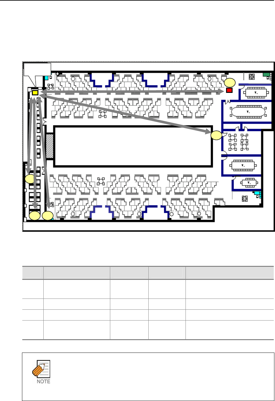
OfficeServ 500 Wireless LAN Service Manual/Ed.00 CHAPTER 3. Installation
© SAMSUNG Electronics Co., Ltd. Page 3-15
7.2 Data Transmission Rate on Terminal Location
Data transmission rate and call quality are subject to the terminal’s location in an
office. Refer to Figure 3.13 and Table 3.2 below.
Figure 3.15 Data transmission rate on Station location
Table 3.2 Data transmission rate on Station location
No. Station location Tx(Mbps) Rx(Mbps) Note
1 WBS24↔Station
(close distance:20CM)
3.97 3.04
2 Test location ‘A’ 3.52 3.05
3 Test location ‘B’ 3.97 3.04
4 Test location ‘C’, ‘D’, ‘E’ Link Fail Link Fail Location ‘C’ and ‘D’ have shields
blocking the signal.
Data Rate
Tx is the rate of data transmitted from the WBS24 to the Station.
Rx may have different test results depending on the performance of the network card
mounted on the Station.
WBS24
A
E
B
D
C

CHAPTER 3. Installation OfficeServ 500 Wireless LAN Service Manual/Ed.00
Page 3-16 © SAMSUNG Electronics Co., Ltd.
This page is intentionally left blank.

CHAPTER 4
© SAMSUNG Electronics Co., Ltd. Page 4-1
MMC Programming
This chapter describes the MMC programming procedures related to the wireless
LAN function.
Method of MMC programming
Only the MMC programming procedures related to the wireless LAN are introduced in
this chapter. Refer to the ‘OfficeServ 500 Programming Description’ for the overall
system MMC programming procedures.
1 Before Programming
This section introduces the basic concepts, the phone buttons used for programming,
and the cautions before starting the programming procedure.
1.1 Programming Overview
The OfficeServ 500 System settings can be easily modified using a connected digital
phone, and the program used to change the system settings through a phone is called
the MMC(Man Machine Communication). The program used for system setting
through a connected laptop computer or a PC is called the PCMMC. The MMC
programs are classified into a program that the subscriber can program and a program
that the subscriber cannot program, depending on the three subscriber levels :
Engineer, Operator, and Subscriber. The Engineer and Operator programming
requires a password for each programming, but the Subscriber programming does not
need a password.

CHAPTER 4. MMC Programming OfficeServ 500 Wireless LAN Service Manual/Ed.00
Page 4-2 © SAMSUNG Electronics Co., Ltd.
1.2 Programming Button
The functions of the phone buttons for MMC programming are listed below.
Table 4.1 Program buttons
Button Function
▲ ▼(Up & Down) Change screen
Dial key Confirm status
Soft key Move cursor
Keypad Select item
SPK key Save data and proceed to next menu
HOLD key Delete previous input
TRSF key Enter program
1.3 Cautions when Programming
Programming shall be done in an idle mode where the handset is on top of the
telephone set.
Programming may be done on any extension of a digital phone.
Programming may not be done on a common single line telephone.
For digital phones not equipped with the LCD screen, use the dial key to enter
the numbers in the Description instead of the [▲volume▼] button. But since
there are no Soft buttons, programming is limited. Therefore, with phones
without the LCD screen, program only the Subscriber programs.
When ‘INVALID DATA’ appears on the LCD screen, re-enter the correct data.
When no key is pressed for an amount of time(key program end time, default is
60 seconds), programming will end and return to idle mode.
When the handset is lifted during programming, programming will end and
return to idle mode.
When programming returns to idle mode by pressing the [SPK] key or the
[TRSF] key, or by lifting the handset, without confirming the modified
data(pressing the ‘left’ or ‘right’ key of the ‘Soft’ button), or when the phone
plug is disconnected, the data entered until then and the data on the LCD screen
will automatically be saved as the new data.

OfficeServ 500 Wireless LAN Service Manual/Ed.00 CHAPTER 4. MMC Programming
© SAMSUNG Electronics Co., Ltd. Page 4-3
1.4 Programming Procedure
This section describes the overall programming procedure. The procedure shall be
read carefully and thoroughly understood.
The programming procedure is described as follows.
Program Procedure Display Screen
1) Press the [TRSF] button, and enter 800.
2) Enter the PASSCODE
(Operator or Engineer password).
3) To enter the MMC, press the dial button [1] or
select the ‘ENABLE’ status by pressing the
[UP & DOWN] button.
4) Enter the program number.
Or, select the program number using the [UP & DOWN] button, and press [SPK].
Or, in an idle mode, press the [TRSF] button and enter the program number.
5) Proceed programming of the selected program.
PROGRAMMING MODE
ENTER PGM ID:
ENABLE TECH PROG
PASSCODE:****
ENABLE TECH PROG
DISABLE TENANT:1

CHAPTER 4. MMC Programming OfficeServ 500 Wireless LAN Service Manual/Ed.00
Page 4-4 © SAMSUNG Electronics Co., Ltd.
2 Programming
This section describes the MMC programming procedure related to the parameter
modification of the 8WLI and the WBS24.
The MMC related to the parameter modification of the 8WLI and the WBS24 are
listed below.
Table 4.2 Wireless LAN related MMC
MMC No. MMC Function
845 Sets 8WLI, WBS24 parameter
846 WIP INFO
847 8WLI RESET/STATUS
848 Setting for the WIP Data terminals
849 8WLI Registration/Release, Encryption Settings
2.1 Setting the MMC845 8WLI Parameter
This MMC modifies the 8WLI parameter.
Set the network configuration with the 8WLI parameters, which are the SYSTEM ID,
the System KEY, and the WBS24.
The system KEY is used internally to distinguish between systems when registering a
terminal. The default value is ‘00000’, but only when this value is modified to
another value, an electric power will be supplied to the WBS24, thus enabling the use
of the WLAN terminal, In addition, the System KEY serves as an identification ID
when the WLAN terminal connects to the WBS24.
The default value of the SYSTEM ID, ‘WBS24’, must be modified to another value
in order to use a multiple system in one area. The DNS setting for WLAN is
additionally described in this menu.
Set the network configuration for eight WBS24s by setting the IP assignment, Netmask,
and Gateway for each WBS24. These settings should be compatible with the Intranet
since the network configuration setting is essential for data service. In addition, the RF
frequency for each WBS24 should be selected. Currently in Korea, up to 14 frequencies
may be selected.
The number of the WBS24 indicates the ID of the BTS for the WBS24. 1 to 24 are
assigned to the WBS24(Combo), and higher numbers than 24 are assigned to the
WBS24(Basic).
The WBS24(Combo) is connected to three WLIs. WBS24(Combo) 1 to 8 are
assigned to WLI 1 and WBS24(Combo) 9 to 16 are assigned to WLI 2.
Also, WBS24(Combo) 17 to 24 are assigned to WLI 3.
Session Initiation Protocol(SIP) variables used for the WBS24(Basic) can be defined.

OfficeServ 500 Wireless LAN Service Manual/Ed.00 CHAPTER 4. MMC Programming
© SAMSUNG Electronics Co., Ltd. Page 4-5
Defaults
WLI : SYSTEM ID WBS24
WLI : SYSTEM KEY 0000
WLI : 2P
PND DNS 0. 0. 0. 0
WLI : 1ST DNS 0. 0. 0. 0
WLI : SYSTEM KEY 34568
WLI : 2 ND WBS IP 168.208.144.10
WLI : CODEC LIST G726
WLI : VERSION
WBS001 : IP ADDR 0. 0. 0. 0
WBS001 : RF CH. 1
WBS001 : STATUS OFF
WBS001 : VERSION
WBS001 : MAC ADDR FFFF FFFF FFFF
WBS001 : NET MASK 255.255.255. 0
WBS001 : GATEWAY 0. 0. 0. 0
SIP : RETRANS T1 000500MS
SIP : RETRANS T2 0004000MS
SIP : RETRANS T4 0005000 ms
SIP : GEN LINGER T 000000MS
SIP : INV LINGER T 32000MS
SIP : STOP GENNR T 000000MS
SIP : STOP INVNR T 000000MS
SIP : GEN REQ T 000000MS
SIP : PROVIS TIME 180000MS
CHAPTER 4. MMC Programming OfficeServ 500 Wireless LAN Service Manual/Ed.00
Page 4-6 © SAMSUNG Electronics Co., Ltd.
Program procedure Display Screen
1) Press the [TRSF] button, and enter 845.
2) Press the [SPK] key to enter the select menu.
When the cursor is at WLI, press the
[UP & DOWN] button and select
WLI or WBS1~254.
3) Press the Soft key and move to the SYSTEM ID.
When the cursor is below SYSTEM ID, press the
[UP & DOWN] key and select the setting menu for
WLI or WBS24.
4) Set the items below at the WLI menu.
SYSTEM ID : Use the Soft key to move the
cursor. Enter the new WLI SYSTEM ID to register.
Press the Soft key and proceed to next register status.
Register the DNS server(second) IP.
Register the DNS server(first) IP.
Register the SYSTEM KEY.
Register the WBS24 second IP.
This is shared between all eight WBS24s.
Caution when setting the WBS24 SECOND IP
To use the Internet network, the first three digits of the IP assigned to the WBS24 and
the first three digits of the SECOND WBS IP of the WBS24 must be identical. If the IP
assigned to the WBS24 and the Station is 168.219.149.xxx, then the SECOND WBS
IP of the WBS24 shall be 168.xxx.xxx.xxx.
845: WLI PARA
SELECT PROG ID
U
W
U
LI : SYSTEM ID
WBS24
U
W
U
BS1: IP ADDRESS
0. 0. 0. 0
WLI : SYSTEM ID
WBS24
WLI : SYSTEM ID
0000
U
W
U
LI : SYSTEM ID
WBS24
WLI : 2
P
P
ND DNS IP
0. 0. 0. 0
WLI : 1 ST DNS IP
0. 0. 0. 0
WLI : SYSTEM KEY 00000

OfficeServ 500 Wireless LAN Service Manual/Ed.00 CHAPTER 4. MMC Programming
© SAMSUNG Electronics Co., Ltd. Page 4-7
Select the voice codec.
Select from the four, G711u, G711, G726, and
G729 CODEC.
Numbers are given from 1 to 4 based on priority.
5) Set the items below at the WBS24 menu.
Register the WBS24 IP ADDRESS.
Register the WBS24 RF CHANNEL.
Displays the WBS24 status.
Displays the WBS24 VERSION.
Displays the WBS24 MAC ADDRESS.
Register the WBS24 NET MASK.
Register the WBS24 GATEWAY.
WLI : CODEC LIST
CODEC 1: G726
WBS001: RF CH.
1
WBS001:STATUS
OFF
WBS001:VERSION
WBS001: MAC ADDR
0000 0000 0000
WBS001: NET MASK
255.255.255. 0
WBS001: GATEWAY
0. 0. 0. 0
WBS001 : IP ADDR
0. 0. 0. 0

CHAPTER 4. MMC Programming OfficeServ 500 Wireless LAN Service Manual/Ed.00
Page 4-8 © SAMSUNG Electronics Co., Ltd.
6) Set the items below at the menu .
Register the RETRANS T1.
The initial re-transmission time if no answer based
on the RFC2543 specification.
The range is 0~9900ms. Default is 500 ms.
Register the RETRANS T2.
The maximum re-transmission time
if no answer based on the RFC2543 specification.
The range is 0~9900ms. Default is 4000ms.
Register the RETRANS T4.
The time the User Agent Server waits
after receiving the ACK message.
Based on the RFC2543 specification.
The range is 0~9900ms. Default is 5000 ms.
Register the GEN LINGER T.
The server shall retransmit the response
during this amount of time
until the requested retransmission is received.
For example, the wait time after sending 200 OK
for INFO. The range is 0~99900ms. Default is 5000 ms.
Register the INV LINGER T.
After the client sends ACK
for the INVITE Final Response,
the client cannot confirm
if the server received the ACK message.
The client waits for this amount of time
after sending ACK for the Final Response.
The range is 0~99900ms. Default is 5000 ms
Register the STOP GENNR T.
Before sending Cancel for General Request,
the User Agent shall wait for this amount of time.
The range is 0~99900ms. Default is 5000 ms.
SIP : INV LINGER T
32000MS
SIP : STOP GENNR T
000500MS
SIP : GEN LINGER T
000000MS
SIP : RETRANS T4
004000MS
SIP : RETRANS T1
000500MS
SIP : RETRANS T2
004000MS

OfficeServ 500 Wireless LAN Service Manual/Ed.00 CHAPTER 4. MMC Programming
© SAMSUNG Electronics Co., Ltd. Page 4-9
Register the STOP INVNR T.
Before sending Cancel for the Invite Request,
the User Agent shall wait for this amount of time.
The range is 0~99900 ms. Default is 5000 ms.
Register the GEN REQ T.
After sending General Request,
he User Agent shall wait for the Final Response
for this amount of time. The range is 0~99900ms.
Default is 5000 ms.
Register the PROVIS TIME.
After receiving the Provision Response,
the User Agent shall wait for this amount of time
until Timeout ends. The range is 0~999900ms.
Default is 180000ms
Related Programs
MMC 846 WIP INFO(Station information)
MMC 847 WLI RESET
(WLI/WBS24 status information and initialization.)
MMC 848 WLI IP LIST(Station IP register)
2.2 Setting the MMC846 WIP Information
This MMC sets up the WIP-5000M wireless terminal’s information.
Defaults
[8601] REGIETERED NO
[8601] PASSWORD 0000
[8601] USER ID 1212
[8601] MAC ADDR
[8601] IP ADDRESS
[8601] IP OFFSET
[8601] WBS NUMBER
[8601] WLI NUMBER
[8601] PHONE TYPE
[8601] LOCATED NO
SIP : GEN REQ T
000000MS
SIP : PROVIS TIME
180000MS
SIP : STOP INVNR T
000000MS

CHAPTER 4. MMC Programming OfficeServ 500 Wireless LAN Service Manual/Ed.00
Page 4-10 © SAMSUNG Electronics Co., Ltd.
Program Procedure Display Screen
1) Press the [TRSF] button, and enter 846.
2) Press the [SPK] key to enter the select menu.
When the cursor is at the phone number,
press the [UP & DOWN] button and
select the current phonenumber information.
Press the Soft key and move to the information
menu of each information menu, and select the
setting menu.
3) Confirm the status of terminal register for each
phone number.
4) Register the PASSWORD of terminal.
5) Register the USER ID of terminal.
6) Displays the MAC ADDRESS
of the registered terminal.
7) Displays the IP ADDRESS
of the registered terminal.
8) Displays the IP OFFSET
of the registered terminal.
9) Displays the WBS NUMBER
of the registered terminal.
10) Displays the WLI NUMBER
of the registered terminal.
11) Displays the PHONE TYPE
of the registered terminal.
12) Displays the location of the registered terminal.
846: WIP INFO
SELECT PROG ID
[8601] REGIETERED
NO
[8601] REGIETERED
NO
[8601] PASSWORD
0000
[8601] MAC ADDR
[8601] USER ID
1212
[8601] IP ADDRESS
[8601] IP OFFSET
[8601] WBS NUMBER
[8601] WLI NUMBER
[8601] PHONE TYPE
[8601] LOCATED
NO

OfficeServ 500 Wireless LAN Service Manual/Ed.00 CHAPTER 4. MMC Programming
© SAMSUNG Electronics Co., Ltd. Page 4-11
Related Programs
MMC 847 WLI RESET
MMC 848 WLI IP LIST
MMC 849 WLI REGIST
2.3 Resetting the MMC847 WIP
This MMC is used for rebooting the 8WLI or the WBS24, by software or
independently. This MMC is also used for initializing the WBS24 or verifying the
current connection status of the WBS24.
Program Procedure Display Screen
1) Press the [TRSF] button, and enter 847.
2) Press the [SPK] key and enter the select menu.
Press the Soft key and confirm initialization of WLI.
3) Press the Soft key, or press [1] to select YES, and
the WLI will be initialized.
4) Press the Soft key, or press [1] to select YES, and
the WBS24 will be initialized.
5) Displays current connection status of the WBS24.
Related Programs
MMC 846 WIP INFO
MMC 848 WLI IP LIST
MMC 849 WLI REGIST
2.4 Setting the MMC848 WIP Lists
This MMC848 is used when viewing the IP list assigned to 8WLI, or when creating a
new IP list. Up to 100 IP lists may be entered. MMC848 command is used for setting
the MAC address of data terminals to use wireless LAN.
847: WLI RESET
SELECT PROG ID
RESTART WLI : 1
RESET NOW ? NO
RESTART WBS : 001
RESET NOW ? NO
WBS STATUS : 001
N N N N N N N N

CHAPTER 4. MMC Programming OfficeServ 500 Wireless LAN Service Manual/Ed.00
Page 4-12 © SAMSUNG Electronics Co., Ltd.
Program Procedure Display Screen
1) Press the [TRSF] button, and enter 848..
2) Press the [SPK] key and enter the select menu.
Press the Soft key to change the IP ADDRESS
while assigning the IP ADDRESS.
3) Use the Soft key to position the cursor at an
IP ADDRESS, and assign the IP ADDRESS by
entering values of 0~255.
4) Numbers next to USED indicates the terminal
number from which the IP ADDRESS was
assigned.
Related Programs
MMC 846 WIP INFO
MMC 847 WLI RESET
MMC 849 WLI REGIST
2.5 Setting the MMC849 WLI REGIST
This MMC is used to enable or disable the register of a WIP500M mobile phone
within the WLAN. This MMC is also used to approve the WEP(Wired Equivalent
Privacy) enabling function where the WLAN is encrypted. The WEP key, which must
be used when WEP is enabled, can be configured with 16 characters or less.
Also, the MMC is used to set MAC addresses in the data terminal in order to use the
wireless LAN.
IP:001 USED
0.0.0.0
848: WLI LISTS
SELECT PROG ID
IP:001 USED
168.0.0.0
IP:001 USED 8601
168.219.149.5

OfficeServ 500 Wireless LAN Service Manual/Ed.00 CHAPTER 4. MMC Programming
© SAMSUNG Electronics Co., Ltd. Page 4-13
Program Procedure Display Screen
1) Press the [TRSF] button, and press 849.
2) Press the [SPK] key to enter the select menu.
Enter the PASSCODE to activate the register.
3) Select ENABLE to register the terminal to the
REGISTER WLI.
4) Select the WEP KEY setting when ENCRYPTION
is selected.
5) Enter WEP KEY values when the WEP KEY is set.
6) Can clear the register status for each terminal also.
7) Press the soft key in the IP to change or allocate
a MAC address.
Related Programs
MMC 846 WIP INFO
MMC 847 WLI RESET
MMC 848 WLI IP LIST
ENTER PASSCODE
****
849: WLI REGIST
SELECT PROG ID
WLI REGISTRATION
ENABLE
WBS WEP SERVICE
DISABLE
WEP KEY
WIP REGIST CLEAR
8601:FORCED
MAC LIST : 01
FFFFFFFFFFFF

CHAPTER 4. MMC Programming OfficeServ 500 Wireless LAN Service Manual/Ed.00
Page 4-14 © SAMSUNG Electronics Co., Ltd.
2.6 Setting the MMC830 Ethernet Parameters
To use the basic type of the WBS24, the system network and MGI should be set.
This MMC provides a mean to configure the Internet Protocol(IP) addressing of the
OfficeServ 500 system MCP2 card. This MMC must be utilized if there are ITP
series phones and/or MGI cards used on the system.
Table 4.3 MMC830 Parameters
Number Parameters Description
00 SYSTEM IP ADDR Specifies the IP address for the MCP2 card.
01 SYSTEM
GATEWAY
Specifies the designated gateway IP address used for contacting
IP devices beyond the local network subnet.
02 SYSTEM NET
MASK
Specifies the IP subnet mask.
This parameter is used by the system to calculate the range of IP
devices(subnet) that are within ‘direct reach’ of the MCP2(without
having to go through the designated network IP gateway).
03 SYSTEM RESET Prompt to restart system MCP2 when system IP address is
changed. This reset is same to FAST RESTART on MMC 811.
04 SYSTEM IP TYPE Defines which IP addressing relationship is used for
communications to and from the MCP2 card.
0 PRIVATE IP ONLY : The system assumes all IP phones and
VoIP connections are on the same network. And all IP
addresses are private IP address.
1 PRIVATE w PUBLIC : The system knows that there is a mixture
of IP phones and VoIP connections on the same network and
on remote network(s), thus communicates accordingly based
upon the entries in MMC 840(for IP phones), MMC 838(for
other VoIP gateways) or MMC 830(for other MCP2).
2 PRIVATE IP ONLY : The system assumes all IP phones and
VoIP connections are on the same network. And all IP
addresses are public IP address.
05 SYSTEM PUBLIC
IP
The MCP2 will originate communications, to IP phones and VoIP
connections outside the local network, using this IP address.
Communications to/from this IP will require involvement of the MGI
card. The system identifies communications to/from this address as
‘public’. This allows devices, on remote networks/subnets, to
establish communications with the system, without exposing your
LAN. See ‘SYSTEM IP TYPE’.
06 SYSTEM MAC
ADDR
For your reference, and cannot be changed. The unique
hardware(MAC) address of the MCP2 card.
07 PCMMC
ADDRESS
When system wants connect to PCMMC, system will be send to
this IP address for connection message. Reserved for future use.
OfficeServ 500 Wireless LAN Service Manual/Ed.00 CHAPTER 4. MMC Programming
© SAMSUNG Electronics Co., Ltd. Page 4-15
Number Parameters Description
08 REMOTE M/A
ADDR
When system wants connect to remote M & A PC, system will be send
to this IP address for connection message. Reserved for future use.
Changing IP address/value
When changing any IP address/value, listed below, three digits must be input for
each(octet) field.
Example) 192.168.1.10 input must be : 192 168 001 010
The first 3 parameters
SYSTEM IP address, system gateway, and system net mask are stored separate
from the main system database, thus will not be defaulted when MMC811 ‘CLEAR
MEMORY’ is performed. Furthermore, any changes to these parameters will not be
applied until the MCP2 is reset.
Program Buttons
VOLUME Used to scroll through options
KEYPAD Used to enter selections
SOFT BUTTONS Move cursor left and right
SPEAKER Used to advance next MMC
Action DISPLAY
1) Press Transfer button and enter 830
Display shows the system IP address.
2) Press Volume button to make selection and
Press Right Soft button to move cursor.
3) Using the keypad enter three digit IP octet
numbers IE 192 168 001 010 for 192.168.1.10
Cursor will return to Step 1 upon completion
of IP address entry.
4) Press Volume button to make selection and
Press Right Soft button to move cursor.
U
S
U
YSTEM IP ADDR
165.213. 97.185
SYSTEM IP ADDR
U
1
U
65.213. 97.185
SYSTEM IP ADDR
192.168.001.01
U
0
U
S
U
YSTEM GATEWAY
165.213. 97. 1

CHAPTER 4. MMC Programming OfficeServ 500 Wireless LAN Service Manual/Ed.00
Page 4-16 © SAMSUNG Electronics Co., Ltd.
5) Using the keypad enter three digit IP octet numbers
IE 192 168 001 001 for 192.168.1.1
Cursor will return to Step 5 upon completion
of system gateway entry.
6) Press Volume button to make selection and
press Right Soft button to move cursor.
7) Press Volume button to make selection and
press Right Soft button to store and move cursor.
8) Press Transfer button and enter to exit
OR
Press Speaker button to advance next MMC.
Default Data
SYSTEM IP ADDR : 165.213.97.185
SYSTEM GATEWAY : 165.213.97.1
SYSTEM NET MASK : 255.255.255.0
SYSTEM RESET : NO
SYSTEM IP TYPE : PRIVATE IP ONLY
SYSTEM PUBLIC IP : 1.1.1.1
SYSTEM MAC ADDR : CARD DEPENDANT
PCMMC ADDRESS : 168.219.1.101
REMOTE M/A ADDR : 168.219.1.102
Related Items
MMC 615 MGI GROUP
MMC 831 MGI PARAMETERS
MMC 833 VOIP ADDRESS TABLE
MMC 838 PRIVATE IP ADDRESSES
MMC 840 IP SET INFO
MMC 841 SYSTEM IP OPTIONS
SYSTEM GATEWAY
192.168.001.00
U
1
SYSTEM RESTART
ARE YOU SURE?
U
N
U
O
U
S
U
YSTEM RESTART
ARE YOU SURE? NO
OfficeServ 500 Wireless LAN Service Manual/Ed.00 CHAPTER 4. MMC Programming
© SAMSUNG Electronics Co., Ltd. Page 4-17
2.7 Setting the MMC831 MGI Parameters
This MMC provides a mean to configure the Internet Protocol(IP) addressing of the
MGI card(s). This MMC must be utilized MGI card(s) used on the system.
Table 4.4 MMC831 Parameters
Number Parameters Description
0 IP ADDRESS Specifies the IP address for the MGI card.
1 GATEWAY Specifies the designated IP gateway address used for contacting IP
devices beyond the local subnet.
2 SUB MASK Specifies the IP subnet mask. This parameter is used by the system to
calculate the range if IP devices(subnet) that are within ‘direct reach’
of the MGI(without having to go through the designated network IP
gateway).
3 PUBLIC IP The MGI will originate communications, to IP phones and VoIP
connections outside the local network, using this IP address. If this
IP address sets 0.0.0.0, 255.255.255.255 or default value then this
MGI card uses private IP only. See System IP Type on MMC 830.
4 STS PERIOD No entry required. Designates the timed message cycle to check the
remote IP status of MGI3 S/W.
5 VERSION No entry required. Used to indicate revision of MGI3 S/W.
6 MAC ADDR For your reference, and cannot be changed. The unique
hardware(MAC)
address of the MGI card.
7 CARD RESET Prompt to restart MGI card when IP address is changed. This use
for MGI 1 and 2 only, MGI3 is self restart automatically.
A MGI card
This MMC cannot be accessed unless there is a MGI card installed in the system.
Program Buttons
VOLUME Used to scroll through options
KEYPAD Used to enter selections
SOFT BUTTONS Move cursor left and right
SPEAKER Used to advance next MMC

CHAPTER 4. MMC Programming OfficeServ 500 Wireless LAN Service Manual/Ed.00
Page 4-18 © SAMSUNG Electronics Co., Ltd.
Action DISPLAY
1) Press Transfer button and enter 831
Display shows the first MGI card
2) Enter MGI number
OR
Press Volume button to make selection and
press Right Soft button to move cursor
Press Volume button to make selection and
press Right Soft button to move cursor.
3) Enter MGI parameter number
OR
Press Volume button to make selection and
press Right Soft button to move cursor.
Press Volume button to make selection and
press Right Soft button to move cursor.
4) Enter MGI parameter
OR
Press Right Soft button to move cursor.
Press Right Soft button to move cursor.
5) Press Transfer button and enter to exit
OR
Press Speaker button to advance next MMC.
Default Data
IP ADDRESS : 1.1.1.1
GATEWAY : 1.1.1.1
SUB MASK : 255.255.255.0
PUBLIC IP : 1.1.1.1
STS PERIOD : 00 SEC
VERSION : V4
CARD RESET : NO
Related Items
MMC 615 MGI GROUP
MMC 830 ETHERNET PARAMETERS
MMC 838 PRIVATE IP ADDRESSES
MMC 840 IP SET INFOMATION
MMC 841 SYSTEM IP OPTIONS
[
U
3
U
801] IP ADDRESS
168.219. 76.101
[3801]
U
I
U
P ADDRESS
168.219. 76.101
[3801] IP ADDRESS
U
1
U
68.219. 76.101
[3801]
U
I
U
P ADDRESS
165. 10. 1.100

CHAPTER 5
© SAMSUNG Electronics Co., Ltd. Page 5-1
Maintenance
This chapter describes how to solve problems via a LED status of WBS24, how to
verify the WBS24 using a web browser and how to upgrade the WBS24 software.
1 Verifying the Status of WBS24
1.1 Status inquiry via the LED Status Indicators
With the LED indicators on the front panel of the WBS24, it is possible to verify the
WBS24 status. When power is supplied to the WBS24, booting is allowed about ten
minutes later. At this time, booting is indicated as the LD2 LED blinks regularly.(At
this time, other LEDs can be unintentionally turned on, but they should be ignored).
After receiving the initialized data from the system and when booting is completed,
the LD2 LED blink will be disappeared. From this time, the on-line service becomes
practicable. After booting is completed, each LED indicator of on-line status contains
the uses as shown below.

CHAPTER 5. Maintenance OfficeServ 500 Wireless LAN Service Manual/Ed.00
Page 5-2 © SAMSUNG Electronics Co., Ltd.
Table 5.1 WBS24 LED Status and Meaning of the WBS24
LED Name Function Blue On Blue Off Blue Blinking
PWR Status of Power Supply Normal power
supply
No power supply -
WLAN Operating status of
wireless LAN
Normal operation
of wireless LAN
No operation of
wireless LAN
Data being
received and
transmitted via
wireless LAN
LAN Operation status of
LAN
Normal operation
of LAN
No operation of
LAN
Data being
received and
transmitted via
LAN
WLI Connection status with
the 8WLI
Normally
connected with
the 8WLI card
Not connected
with the 8WLI
card
Data being
received and
transmitted via the
8WLI card and the
DASL line
LD1 Indicating the B
channel in use
Refer to the table below
LD2 Indicating the B
channel in use
Table 5.2 Status of WBS24 LD1, LD2 LEDs
The number of B channels
being communicated LED status of the LD1 LED status of the LD2
0 Blue LED Off Blue LED Off
One Blue LED Blinking Periodically Blue LED Off
Two Blue LED Off Blue LED Off
Three Blue LED Off Blue LED Blinking Periodically
Four Blue LED Off Blue LED Off
1.1.1 Booting Failure
When the WBS24 fails to boot up, it means that the flash memory with the program
is not functioning. All of the 5 LEDs, except the PWR, blink periodically at the same
time to inform the fault status. The flash memory might be broken when the process
of the WBS24 upgrade is interrupted, and the fault status can be removed using ‘the
upgrade using the network booting’ method.

OfficeServ 500 Wireless LAN Service Manual/Ed.00 CHAPTER 5. Maintenance
© SAMSUNG Electronics Co., Ltd. Page 5-3
1.1.2 Troubleshooting
The troubleshooting steps according to the LED status of WBS24 are explained in the
following flowchart.
Figure 5.1 WBS24 Troubleshooting Flow Charts
Operation fault of the WLAN
Verify the PCMCIA card
NO
- If the same status continues after
resetting two or three times, the
flash memory image is damaged.
- Upgrade via the network.
POWER ON
PWR LED ON
The other LEDs except the PWR LED
blink periodically.
The LD2 LED blinks continuously
LAN LED ON
(BLINK)
WLI LED
ON
Operation fault of the LAN
Verify the LAN line
Not connected
with the 8WLI .
Bootin
g
com
p
letin
g
and online status
- Verify the system power
- Verify the 8WLI status, or
8WLI connection line
NO
YES
NO
NO
NO
YES
YES
YES YES NO
- Verify the MMC setting and
values
WLAN LED ON
(BLINK)
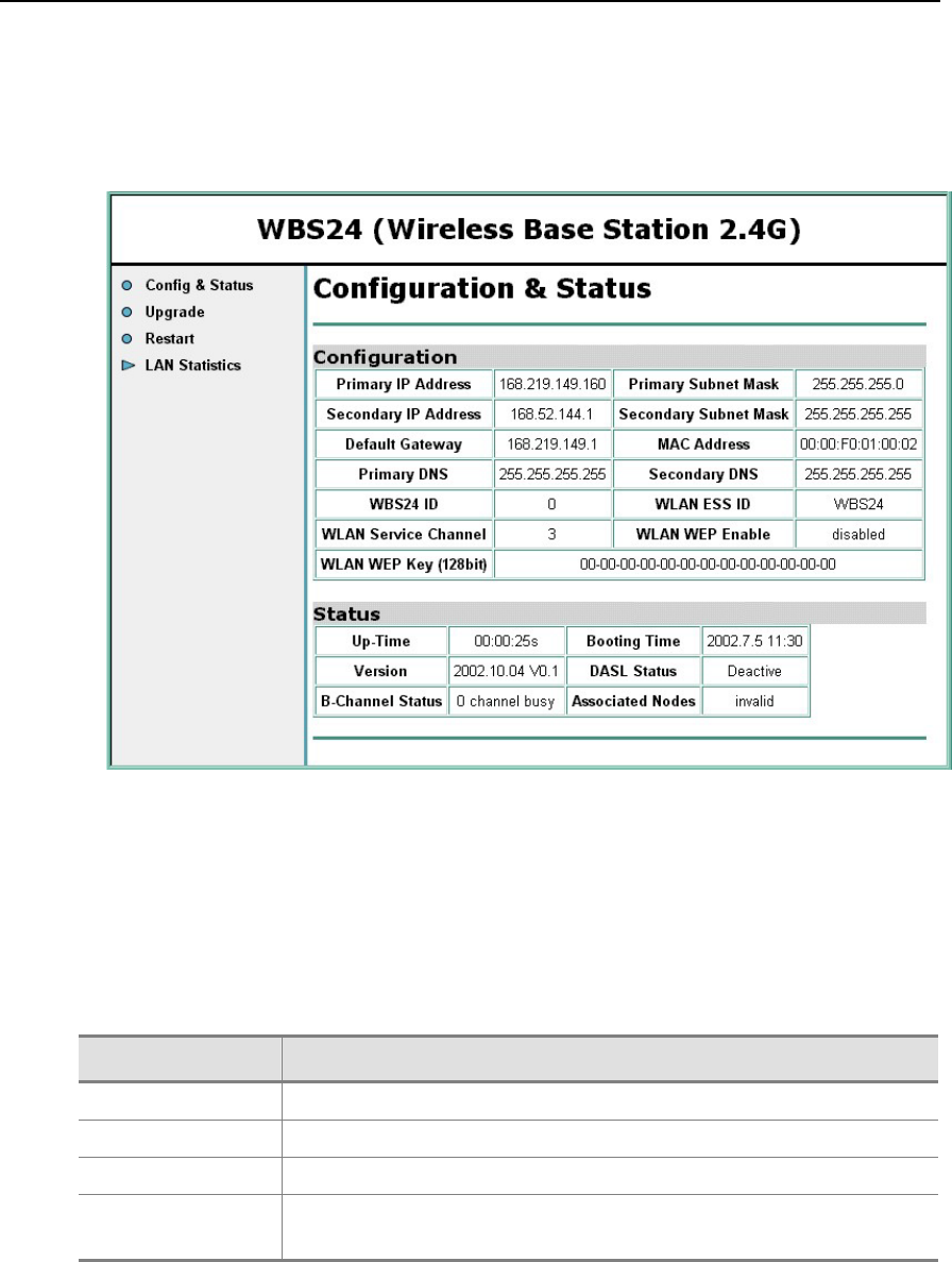
CHAPTER 5. Maintenance OfficeServ 500 Wireless LAN Service Manual/Ed.00
Page 5-4 © SAMSUNG Electronics Co., Ltd.
1.2 Status Inquiry via a Web Browser
When the IP address of WBS24 is connected via a wired cable or wirelessly to the PC,
the initialization screen will be displayed.
Figure 5.2 Web screen for inquiring the WBS24 status (Initial screen)
1.2.1 Description on Main Menu
4 main menus are located on the left side of the screen. The functions of each menu
are shown below.
Table 5.3 Main menu of the web screen for inquiring the WBS24 status
Menu Function
Config&Status Possible to inquire various configuration values and statuses
Upgrade Possible to upgrade S/W of the WBS24
Restart Used when restarting the WBS24
LAN Statistics Indicates statistical information on received and transmitted data of the
WLAN and the Ethernet
Let’s find out more about screens by each menu and function.
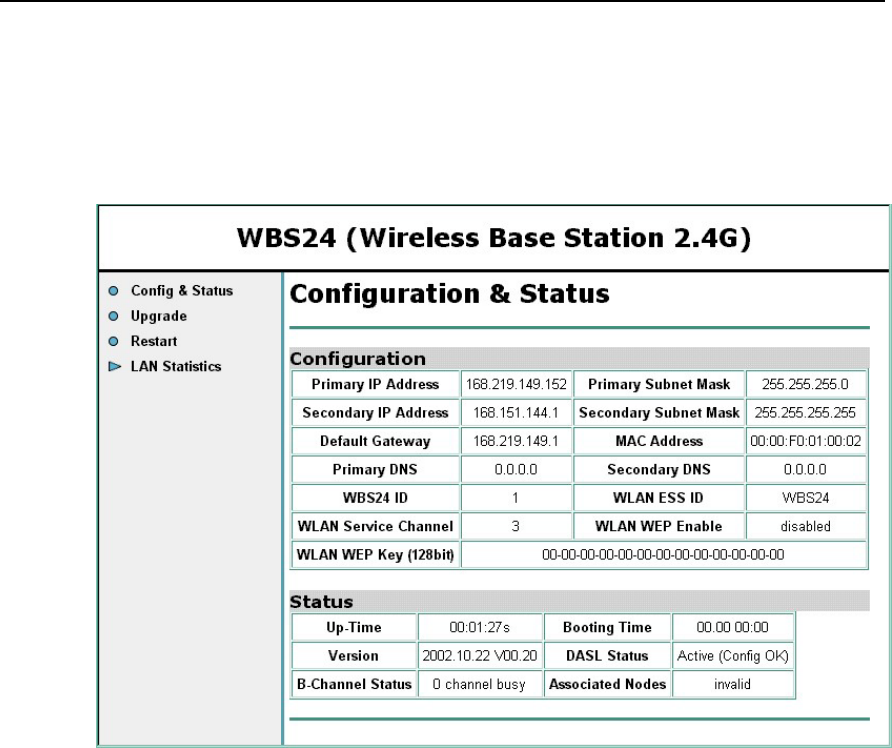
OfficeServ 500 Wireless LAN Service Manual/Ed.00 CHAPTER 5. Maintenance
© SAMSUNG Electronics Co., Ltd. Page 5-5
1.2.2 Inquiry of Config & Status
With the selected [Config & Status] menu, the established value and status regarding
the LAN and the WLAN can be inquired.
Figure 5.3 Web screen for inquiring the WBS24 status (Config & Status)
Status items are shown below.
Up-Time : the passed time after booting
Booting Time : the final time of WBS24 booting
Version : Information on the WBS24 version
DASL Status : Connection status with the 8WLI
− Deactive : Not activated status of the DASL line
− Active(Not Config) : DASL line is activated, and the initialized message is
not received from the system.
− Active(Config OK) : DASL line is activated, and the initialized message is
received from the system.
B-channel Status : the number of traffics being in use at present
Associated Nodes : Unavailable at present
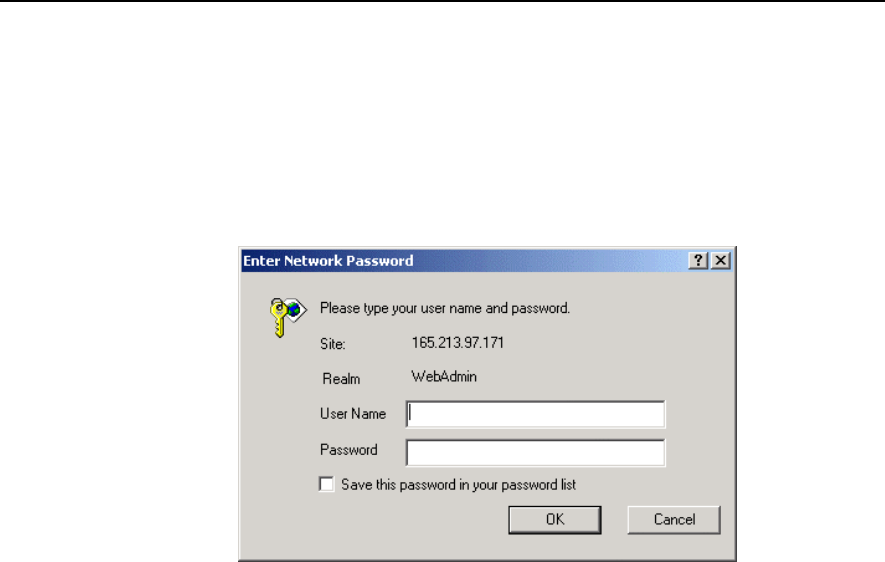
CHAPTER 5. Maintenance OfficeServ 500 Wireless LAN Service Manual/Ed.00
Page 5-6 © SAMSUNG Electronics Co., Ltd.
1.2.3 Upgrading S/W
With the selected [Upgrade] menu, the WBS24 software can be upgraded. At the first
time connection, the user name and password will be asked. Enter the user name and
password by inquiring from the system manager.
(Example : a user name and password are initially set as 'wlan’)
Figure 5.4 Web screen for inquiring the WBS24 status (Screen for entering password)
For the software upgrade, refer to ‘2.Upgrading the WBS24 S/W’ in chapter5.
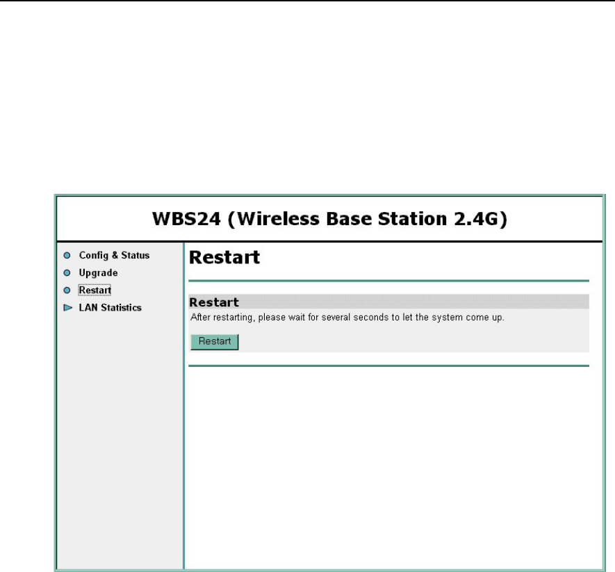
OfficeServ 500 Wireless LAN Service Manual/Ed.00 CHAPTER 5. Maintenance
© SAMSUNG Electronics Co., Ltd. Page 5-7
1.2.4 Restarting WBS24
By selecting the [Restart] menu, the WBS24 can be restarted.
When connecting for the first time, the user name and password will be asked. Enter
the user name and password by inquiring from the system manager.( Example : a user
name and password are initially set as 'wlan’) When the screen as shown below is
displayed, click the [Restart] button to restart the WBS24.
Figure 5.5 Web screen for inquiring the WBS24 status (Restart)
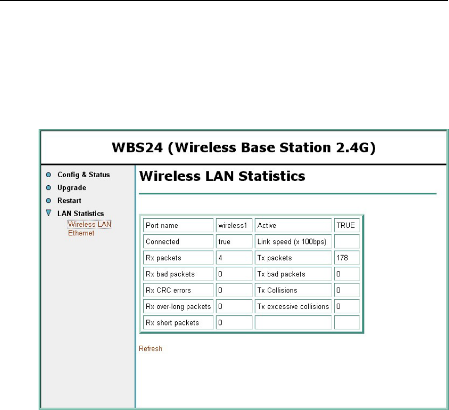
CHAPTER 5. Maintenance OfficeServ 500 Wireless LAN Service Manual/Ed.00
Page 5-8 © SAMSUNG Electronics Co., Ltd.
1.2.5 Inquiring Statistical Information of Block LAN
With the selected [LAN Statistics] menu, statistical information on data transmitted
and received through the WLAN and the Ethernet can be inquired. Two sub menus
will be displayed, so the statistical information by each sub-menu can be inquired.
Inquiry screen of Wilress LAN statistics
Figure 5.6 Web screen for inquiring the WBS24 status (Wireless LAN statistics)
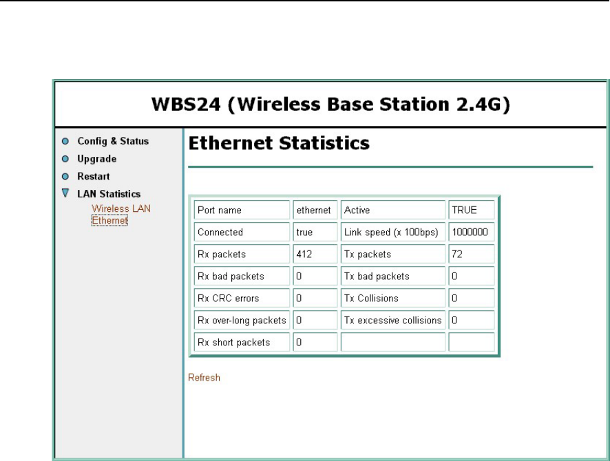
OfficeServ 500 Wireless LAN Service Manual/Ed.00 CHAPTER 5. Maintenance
© SAMSUNG Electronics Co., Ltd. Page 5-9
Inquiry screen of the Ethernet statistics
Figure 5.7 Web screen for Inquiring the WBS24 Status (Ethernet statistics)

CHAPTER 5. Maintenance OfficeServ 500 Wireless LAN Service Manual/Ed.00
Page 5-10 © SAMSUNG Electronics Co., Ltd.
2 Upgrading the WBS24 S/W
WBS24 S/W is upgraded in the following two methods.
Use the web browser screen
Use the network booting
It is recommended to use the web browser method that the setting is easy and the
usage is simple.
When the WBS24 generates a fault due to the flash memory that is not
functioning(When all the 5 LEDs of the WBS24 blink, except the PWR LED), the
WBS24 can be recovered/upgraded using the network booting method.
2.1 Upgrading via the Web Browser
The method of using the web screen is different according to what types of the
WBS24 connection is made, whether by wire or by wireless. Each type is described
in the following section.
2.1.1 Wireless Connection
Preparing Materials
PC(PC or laptop computer is recommended) that is loaded with the WLAN
NIC(Network Interface Card) card.
Upgrade file for HTTP(tar type)
Upgrade Procedure
1) After placing the PC within about 10M from the WBS24, bring up the web
browser by connecting the IP address of the WBS24 wirelessly. The IP address
of the WBS24 is set from the system, and the established value can be inquired
through the MMC 845. Verify if the DASL status is ‘Active(Config OK)’ on the
connected web screen. If the status is not ‘Active(Config OK)’ after reloading
the web screen, wait for the active status.
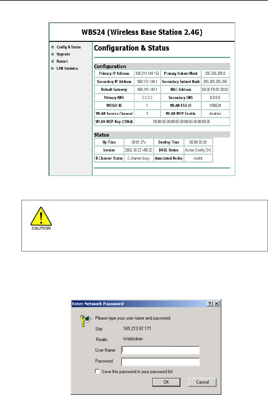
OfficeServ 500 Wireless LAN Service Manual/Ed.00 CHAPTER 5. Maintenance
© SAMSUNG Electronics Co., Ltd. Page 5-11
Figure 5.8 Web screen for upgrading the WBS24 S/W (Initial screen)
Cautions against the roaming of the WBS24
If the PC is roamed to another WBS24 while upgrading, the upgrade will be
interrupted and the flash memory will not be functioning. Accordingly, locate the PC
as close as possible from the WBS24. To prevent roaming to another WBS24, it is
recommended that all of the WBS24 power should be turned off for safety.
2) Select the [Upgrade] menu. The user name and password will be asked if
connected for the first time. Enter the user name and password by inquiring from
the system manager.(Example : User name, Password-wlan)
Figure 5.9 Web screen for upgrading the WBS24 S/W (Screen to enter a password)
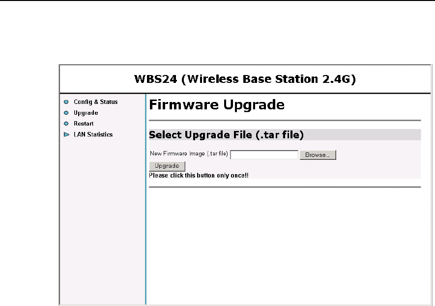
CHAPTER 5. Maintenance OfficeServ 500 Wireless LAN Service Manual/Ed.00
Page 5-12 © SAMSUNG Electronics Co., Ltd.
3) If a user is authorized successfully, the following screen will show up. Click the
[Indexing] button. Select the prepared upgrade file(.tar type)
Figure 5.10 Web screen for inquiring the WBS24 S/W (Firmware upgrade)
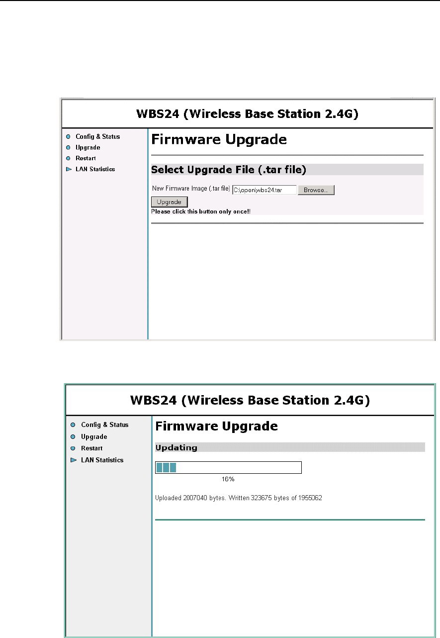
OfficeServ 500 Wireless LAN Service Manual/Ed.00 CHAPTER 5. Maintenance
© SAMSUNG Electronics Co., Ltd. Page 5-13
4) Click the [Upgrade] menu when the following screen is displayed. At this time,
click the [Upgrade] button only once. The upgrade is preceded. The required
time may vary according to the WBS24 status, but it is about three or four
minutes.
Figure 5.11 Web screen for inquiring the WBS24 S/W (Click the [Upgrade] button)
Figure 5.12 Web screen for inquiring the WBS24 S/W (In the process of upgrade)
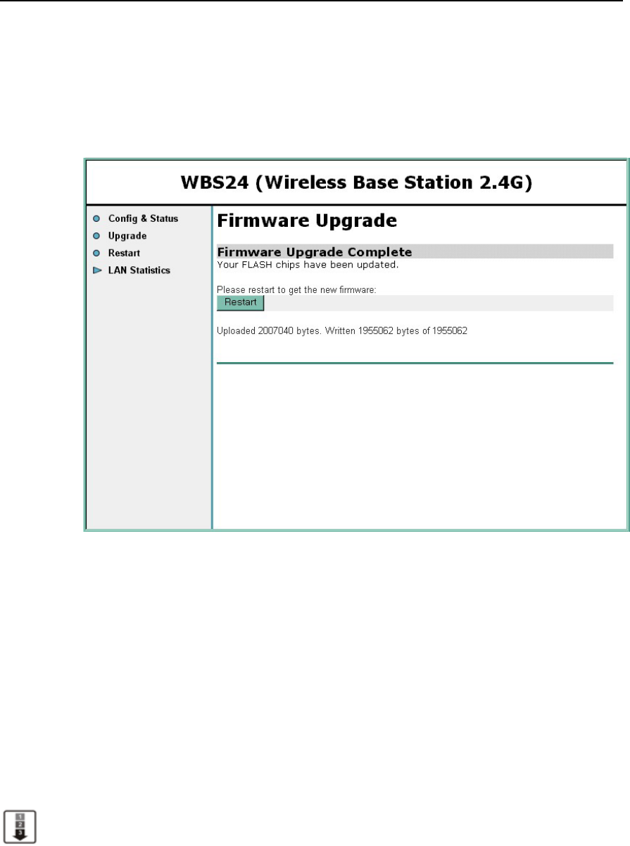
CHAPTER 5. Maintenance OfficeServ 500 Wireless LAN Service Manual/Ed.00
Page 5-14 © SAMSUNG Electronics Co., Ltd.
5) When the upgrade is completed, the following screen will show up. The upgrade
contents are not applied at this time, and it is applied when restarting the
WBS24. If the upgrade contents are needed to apply immediately, click the
[Restart] button and restart the WBS24. After restarting, verify the version on
the web screen.
Figure 5.13 Web screen for upgrading the WBS24 S/W (Firmware Upgrade Complete)
6) When several units of WBS24 are installed, repeat No.1~No.5 by moving the PC
to each WBS24.
2.1.2 Wired Connection
Preparing Materials
PC(PC or laptop computer) that is loaded with the wire LAN port.
Upgrade file for HTTP(tar type)
Upgrade Procedure
1) After connecting the PC to the wired LAN, connect to the IP address of WBS24.
Bring up the web browser. The IP address of the WBS24 is established at the
system, and the established value can be inquired via the MMC 845. Verify if the
DASL status is ‘Active(Config OK)’ on the web screen. If the status is not
‘Active(Config OK)’, reload the screen and wait for the status.
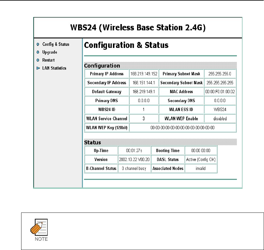
OfficeServ 500 Wireless LAN Service Manual/Ed.00 CHAPTER 5. Maintenance
© SAMSUNG Electronics Co., Ltd. Page 5-15
Figure 5.14 Web screen for inquiring the WBS24 S/W (Initial screen)
Wireless Connections
It is not necessary to move the PC to the front of the WBS24 for the wireless
connections.
2) The subsequent procedure is as same as No.2 ~No.5 of ‘Upgrading the wireless
connection.’ When several units of WBS24 are installed, upgrade according to
the procedures as described above by connecting to the relevant IP address of
the WBS24.
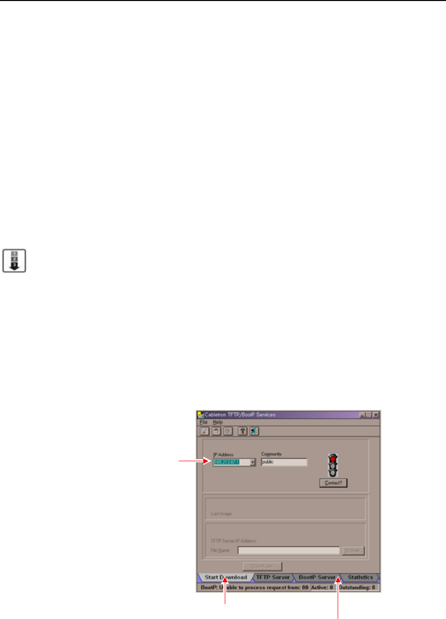
CHAPTER 5. Maintenance OfficeServ 500 Wireless LAN Service Manual/Ed.00
Page 5-16 © SAMSUNG Electronics Co., Ltd.
2.2 Upgrading via the Network Booting
This method is used to recover an error such as non-functioning flash memory.
This method is impossible to upgrade wirelessly, but only through a wired LAN.
If the WBS24 is connected with a wired LAN, it is possible to upgrade without any
change on the WBS24. But if not the case, the wired LAN shall be connected
between the WBS24 and the PC in order to upgrade the WBS24. This section
describes how to upgrade the WBS24 based on the assumption that the WBS24 is
connected to the wired LAN.
Preparing Materials
PC server with a wired LAN port
Upgrade file for the network booting(bin type)
Upgrade Procedure
1) Set the PC to the TFTP/BootP Server for the network booting. Set the PC by
using an application program for PC. This description explains how to set up
using the ‘Cabletron TFTP/BootP Services 2.0 S/W. When another S/W is used,
refer to the relevant usage of S/W. The following describes how to set up
‘Cabletron TFTP/BootP Services 2.0 S/W’.
Receive the program and execute the Setup procedure to set up the program.
Execute the program(When designating a default directory, execute
‘C:\TFTPBOOT\BIN\TFTPBOOT.EXE’) and click the [Start Download] button.
Enter IP of the installed PC and click the [BootP Server] button.
Figure 5.15 Upgrading the WBS24 S/W via the Network Booting (1)
# Enter the IP of installed PC
and press the Enter key
$Press the BootP Server button
" Press the Start Download button
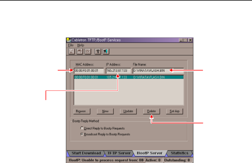
OfficeServ 500 Wireless LAN Service Manual/Ed.00 CHAPTER 5. Maintenance
© SAMSUNG Electronics Co., Ltd. Page 5-17
Then the following screen will show up. After entering the MAC Address, IP
Address and File Name, click the [Update] button.
Figure 5.16 Upgrading the WBS24 S/W via the Network Booting (2)
2) Turn off the power of WBS24 and turn it on again. Then upgrading is performed
automatically. If upgrading is not performed and the error LED is repeated,
verify the connection status of the wired LAN or the setting status of
TFTP/BootP server. If upgrading is normally completed, the WLAN, LAN and
WLI LEDs will be turned on as a Blue color after booting. Verify the S/W
version on the web screen.
" Enter the MAC
address of AP
where to receive
the file from
$ Enter the pathe and
name of the file
that AP will receive,
or select the file
by clicking the browser
at the botton
% Click the Update
button
# Enter the IP
that AP is to
be assigned for
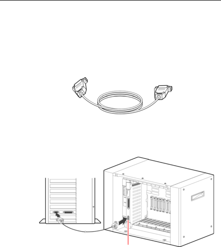
CHAPTER 5. Maintenance OfficeServ 500 Wireless LAN Service Manual/Ed.00
Page 5-18 © SAMSUNG Electronics Co., Ltd.
3 Upgrading the 8WLI S/W
3.1 Connecting the Console Terminal to the 8WLI Card
1) In order to upgrade the 8WLI card software, either PC with the terminal
emulation on, such as a console terminal, or an ASCII terminal like VT-100 and
VT-220 types is used. When connecting the console terminal to the 8WLI card,
the console cable with 9-pin RS-232C connector as shown below is used.
Figure 5.17 Connecting Cable of the Console Terminal
2) Connect one end of the console to the RS-232C connector of the 8WLI card, and
connect the other end to the serial port of the console terminal(PC).
Figure 5.18 Connecting the Console Terminal to the 8WLI Card
RS-232C connector
Console cable
Console terminal

OfficeServ 500 Wireless LAN Service Manual/Ed.00 CHAPTER 5. Maintenance
© SAMSUNG Electronics Co., Ltd. Page 5-19
3.2 Configuring the Console Terminal
The values of the console terminal to be used are configured as shown below.
Emulation : compatible with VT-100/ANSI
Bits per second : 9600 bps
Stop bit : 1
Data bit : 8
Parity bit : None
Flow control : None
The method of setting the console terminal can be different according to the terminal
type or the management system. The file(WLIROM.HEX, MWLIROM.HEX) is
loaded to the 8WLI card in the following two methods.
Using the Tera terminal of the Windows 95/98 operating system
Using the ‘qmodem.exe’ on the DOS window
3.2.1 Loading a File with the Tera Terminal
1) Turn on the PC(Windows95/98 O/S).
2) Execute the Tera terminal program
3) If console terminal is not connected, ‘Cannot open COM1’ message windows
appears. Then, Click the <file><New Connection> to open the new window.
4) Select the <Setup><Serial Port> from the new window, and set as shown
below then click the [Ok] button.
Bits per second : 9600 bps
Stop bit : 1
Data bit : 8
Parity bit : None
Flow control : None
5) Then a new Tera terminal will show up.
CHAPTER 5. Maintenance OfficeServ 500 Wireless LAN Service Manual/Ed.00
Page 5-20 © SAMSUNG Electronics Co., Ltd.
Upgrading a New Software
The 8WLI card can upgrade the software by downloading WLIROM HEX file and
MWLIROM.HEX file via the console terminal. After storing both files in the console
terminal, download them following the method below.
1) When the 8WLI card is normally operated, the following message will show up.
Click the [ENTER] key.
VoWLAN Console <8-Port WLI Board>
2) Enter the ‘flo’ command at the prompt and click the [ENTER] key, the following
massage will show up.
<WLI>flo
================== Select One =======================
[1] Single WLI HEX FILE Loading <Addr = 0x00110000>
[2] Multi WLI HEX FILE Loading <Addr = 0x00190000>
[R] Restart
Prevention of executing the ‘flo’ command
If the ‘flo’ command is executed, the power of all base stations connected to the 8WLI
card is turned off and their wireless LAN function will be interrupted.
3) Select ‘1’ and load the WLIROM.HEX file, from the PC to the 8WLI card. Then
the following message will show up.
Selected 1> Single- WLI HEX FILE Loading
Please Start Loading!!
4) Click the ‘Send file’ on the File Menu of the Tera terminal window.
5) Then the <Sending the text file> window will show up. Select the WLIROM
HEX file and click the [Ok] button.
6) While the WLIROM HEX file is being transmitted to the 8WLI card, the
transmitted contents will be indicated on the screen. If the file transmission is
completed, information on the transmitted HEX file will show up. It takes about
fifteen minutes to send the file to the 8WLI card.

OfficeServ 500 Wireless LAN Service Manual/Ed.00 CHAPTER 5. Maintenance
© SAMSUNG Electronics Co., Ltd. Page 5-21
=========HEX FILE INFORMATION ======================
HEX FILE START ADDR = 0x00110000
HEX FILE END ADDR = 0x0013465D
HEX FILE TOTAL ADDR = 0x0002465D
=========== FLASH MEMORY WRITE START===============
STEP 1. SECTOR ERASE SUCCESS
STEP 2. PROGRAM WRITE SUCCESS
=========== FLASH MEMORY WRITE END ===============
Please [R] key to Restart or [L] key to Loading Again !!
7) Enter ‘L’, and then the following menu will show up. Enter ‘2 to transmit the
MWLIROM.HEX file to the 8WLI card.
<WLI> flo
============ Select One =================
[1] Single WLI HEX FILE Loading <Addr = 0x00110000>
[2] Multi WLI HEX FILE Loading <Addr = 0x00190000>
[3] Restart
8) Click the ‘Send file’ on the File Menu of the Tera terminal window.
9) Then the <Sending the text file> window will show up. Select the
MWLIROM.HEX file and click the [Ok] button.
10) Enter ‘R’. If two HEX files are properly transmitted, the following screen will
show up.
*************************************************
* VoWLAN Console <8-Port WLI Board > *
*************************************************
CHAPTER 5. Maintenance OfficeServ 500 Wireless LAN Service Manual/Ed.00
Page 5-22 © SAMSUNG Electronics Co., Ltd.
3.2.2 Loading the File with Qmodem
1) Exeute qmodem.exe on the DOS window. This description explains how to load
a file if the installed qmodem version is ‘SST V3.1a’. If another qmodem
version is used, refer to the relevant manual.
2) Click the [Alt+P] key to set the modem value. Then the <Set Modem Speed>
window will show up.
3) Click the [ENTER] key, and check if the <8WLI> prompt is generated or not on
the main window. If the <8WLI> prompt is not generated, the user shall verify
the cable status, the traffic port status of PC, and the setting status of the modem
configuration parameter.
4) Enter the ‘flo’ command at the <8WLI> prompt. Then a new message will be
displayed.
<WLI> flo
============== Select One =============
[1] Single WLI HEX FILE Loading <Addr = 0x00110000>
[2] Multi WLI HEX FILE Loading <Addr = 0x00190000>
[3] Restart
5) Enter ‘1’ and select [1], and then the following message will be displayed on the
main window.
Selected 1> Single – WLI HEX FILE Loading
Please Start Loading !!
6) Click the [Page-Up] to load the selected ROM file to the 8WLI card. Then the
following message will show up.
**[ Upload Protocols]**
* A) Ascii *
* X) Xmodem *
* C) Xmodem CRC *
*R) Relaxed Xmodem *
*Y) 1K-Xmodem *
*B) Ymodem Batch *
*Your choice ? *
**********************

OfficeServ 500 Wireless LAN Service Manual/Ed.00 CHAPTER 5. Maintenance
© SAMSUNG Electronics Co., Ltd. Page 5-23
7) Select the < A)Ascii > menu by clicking [A] button on the <Upload Protocols>
window.
8) Enter the path of the file to be uploaded. For instance, if the file to be uploaded is
located as same as the qmodem file, enter the ‘.\WLIROM.HEX’. If the file to be
uploaded is not located as same as the qmodem file, enter the file name as well as
the whole path of the upload file.
9) If enter the file name, following ‘Upload Files(Transmit)’ window appears
***********************Upload Files(Transmit)*********************
Enter the transfer mode:
1)Prompted 2) Time delay 3) No delay
****************************************************************
10) Enter ‘3’ and then the following 11) message will be displayed. It is possible to
verify the upload status by scrolling the data.
11) If the upload is completed, the following HEX information will be displayed.
The displayed information can be different according to the software version of
the 8WLI. If ‘Flash Memory Write End’is displayed, it means that uploading is
successfully completed.
===========HEX FILE INFORMATION ==========
HEX FILE START ADDR = 0x00110000
HEX FILE END ADDR = 0x00013465D
HEX FILE TOTAL LEN = 0x0002465D
------------ FLASH MEMORY WRITE START -------------
STEP 1. SECTOR ERASE SUCCESS
STEP 2. PROGRAM WRITE SUCCESS
---------- FLASH MEMORY WRITE END ---------------
Please [R] key to Restart or [L] key to Loading Again !!
12) Click [L] and then the following message will show up.
<WLI>file
========== Select One =============
[1] Single WLI HEX FILE Loading <Addr = 0x00110000>
[2] Multi WLI HEX FILE Loading <Addr = 0x00190000>
[R] Restart

CHAPTER 5. Maintenance OfficeServ 500 Wireless LAN Service Manual/Ed.00
Page 5-24 © SAMSUNG Electronics Co., Ltd.
13) Select [2] menu to load the WLIROM..HEX file. Then the following message
will show up.
Selected 1> Single- WLI HEX FILE Loading
Please Start Loading !!
14) Perform No.6)~No.10) as shown above and upload the MWLIROM.HEX file.
Select the MWLIROM.HEX file instead of the WLIROM.HEX file. After
uploading the MWLIROM.HEX file, the following message will show up.
================HEX FILE INFORMATION ====================
HEX FILE START ADDR = 0x00110000
HEX FILE END ADDR = 0x0012465D
HEX FILE TOTAL LEN = 0x0002465D
------------ FLASH MEMORY WRITE START ---------------------
STEP 1. SECTOR ERASE SUCCESS
STEP 2. PROGRAM WRITE SUCCESS
----------- FLASH MEMORY WRITE END ----------------------
Please [R] key to Restart or [L] key to Loading Again !!
The message can be different according to the WLI software version. If ‘Flash
Memory Write End’ shows up, it means that uploading is successfully
completed.
15) Click [R] and restart the 8WLI card. If the file is normally transmitted, the
following main window will show up.
******************************************
* VoWLAN Console < 8- Port WLI Board > *
******************************************

Annex A
© SAMSUNG Electronics Co., Ltd. Annex A-1
WLAN (802.11b/DSSS) Specifications
This annex describes the features and specification of a 802.11b/DSSS standard, a
wireless LAN standard.
1 Feature Comparison with Other Standards
Table A.1 Feature Comparison with WLAN (802.11b/DSSS) Standards
Name of
Standards Used Frequency
Payload
Transmittance
Speed
Modulation
Way Feature
IEEE802.11b 2400~2483.5 MHz
(US, Canada, ETSI)
2400~2497 MHz
(Japan)
1/2/5.5/11 Mbps FHSS,
BPSK,
QPSK,
CCK(DSSS)
CSMA/CA
IEEE802.11a 5 GHz 6/9/~36/48/54Mbps OFDM CSMA/CA
ETSI/BRAN
HiperLAN/Type2
ARIB HiSWANa
5 GHz 6/9/~36/48/54Mbps OFDM Connection-
Type
Bluetooth
IEEE802.15.1
2.4 GHz 1 Mbps FHSS Hybrid-Type
HomeRF SWAP 2.4 GHz 10 Mbps FHSS Hybrid-Type
PWR

Annex A. WLAN(802.11b/DSSS) Specifications OfficeServ 500 Wireless LAN Service Manual/Ed.00
Annex A-2 © SAMSUNG Electronics Co., Ltd.
2 Operating Frequency by Channel and Country
Table A.2 Operating Frequency of WLAN (802.11b/DSSS) by Channel and Country
Channel Frequency
(MHz)
Korea, US/
Canada
European
Telecommunications
Standards
Institute(ETSI)
Spain France Japan
1 2412 Operating Operating
2 2417 Operating Operating
3 2422 Operating Operating
4 2427 Operating Operating
5 2432 Operating Operating
6 2437 Operating Operating
7 2442 Operating Operating
8 2447 Operating Operating
9 2452 Operating Operating
10 2457 Operating Operating Operating Operating
11 2462 Operating Operating Operating Operating
12 2467 Operating Operating
13 2472 Operating Operating
14 2484 Operating

OfficeServ 500 Wireless LAN Service Manual/Ed.00 Annex A. WLAN(802.11b/DSSS) Specifications
© SAMSUNG Electronics Co., Ltd. Annex A-3
3 Definitions and Features by Layer
3.1 Physical Layer
DSSS Physical Layer
DSSS physical layer diffuses data to 11 bit Barker words before sending the data.
11 bit Barker words have 10.4 dB of processing gain that meets FCC Part 15.247.
All clients use the same 11 bit Barker words.
DSSS physical layer has a total of 14 channels and null-to-null bandwidth is 22 MHz.
Frequency scope is from 2.400 MHz through 2.483 MHz. It has 3 non-overlapping
channels.
Modulation ways for each data rate and other information are as follows.
Table A.3 Information on the Data Rate of DSSS Physical Layer
Data Rate Code Length Modulation Symbol Rate Bits/Symbol
1 Mbps 11(Barker Sequence) BPSK 1 MSps
(Mega Symbol per Sec)
1
2 Mbps 11(Barker Sequence) QPSK 1 MSps 2
5.5 Mbps 8(CCK) QPSK 1.375 MSps 4
11 Mbps 8(CCK) QPSK 1.375 MSps 8
FHSS Physical Layer
FHSS physical layer supports 2 level GFSK 1 Mbps of basic rate as well as 4 level
GFSK 2Mbps optionally.
It has 79 channels and the bandwidth of each channel is 1 MHz. It hops 2.5 per
second. This is a provision for spreading in FCC Part 15.247. FHSS physical layer
has 22 hop patterns as well.
Infrared Physical Layer
Infrared physical layer uses pulse position modulation(PPM) having 4 or 6 levels.
Operating data rates are 1 Mbps and 2 Mbps.

Annex A. WLAN(802.11b/DSSS) Specifications OfficeServ 500 Wireless LAN Service Manual/Ed.00
Annex A-4 © SAMSUNG Electronics Co., Ltd.
3.2 MAC Layer
MAC layer supports both an ad-hoc network and a client/server infrastructure
network. CSMA/CA are base on distributed coordination function(DCF) and uses
random back off algorithm to prevent the layer from collide with other media.
Point coordination function(PCF) is optional and is used for adjusting the priority of
media.
PCF enables access point to operate as point coordinator in basic service coverage
areas and clients get priority. PCF is suitable for time-bounded services such as voice
application.
The details of CSMA/CA are as follows.
Carrier Sense Multiple Access/Collision Avoidance (CSMA/CA)
Standardized 802.11 uses CSMA to implement peer to peer as a basic connection way
because CSMA expands the connection way of Ethernet(IEEE802.3) to wireless
network.
It is not easy to detect collision in CSMA unlike cable media. Since there is a station
that fails to detect carriers within a section due to hidden terminals, A CSMA/CA
with Ack way reserving transmittance time using RTS/CTS frame and returning Ack
frame for checking transmittance is used.
Since CSMA is based on Distribution Coordination Function(DCF), the time of
gap(IFS) for sending CTS and Ack frames that operators do not want to disconnect to
CSMA is supposed to be shorter than that of IFS for sending RTS or data frames.
In addition, associated IFS should be used when an error occurs due to Point
Coordination Function PCF) and interference in Access Point AP).
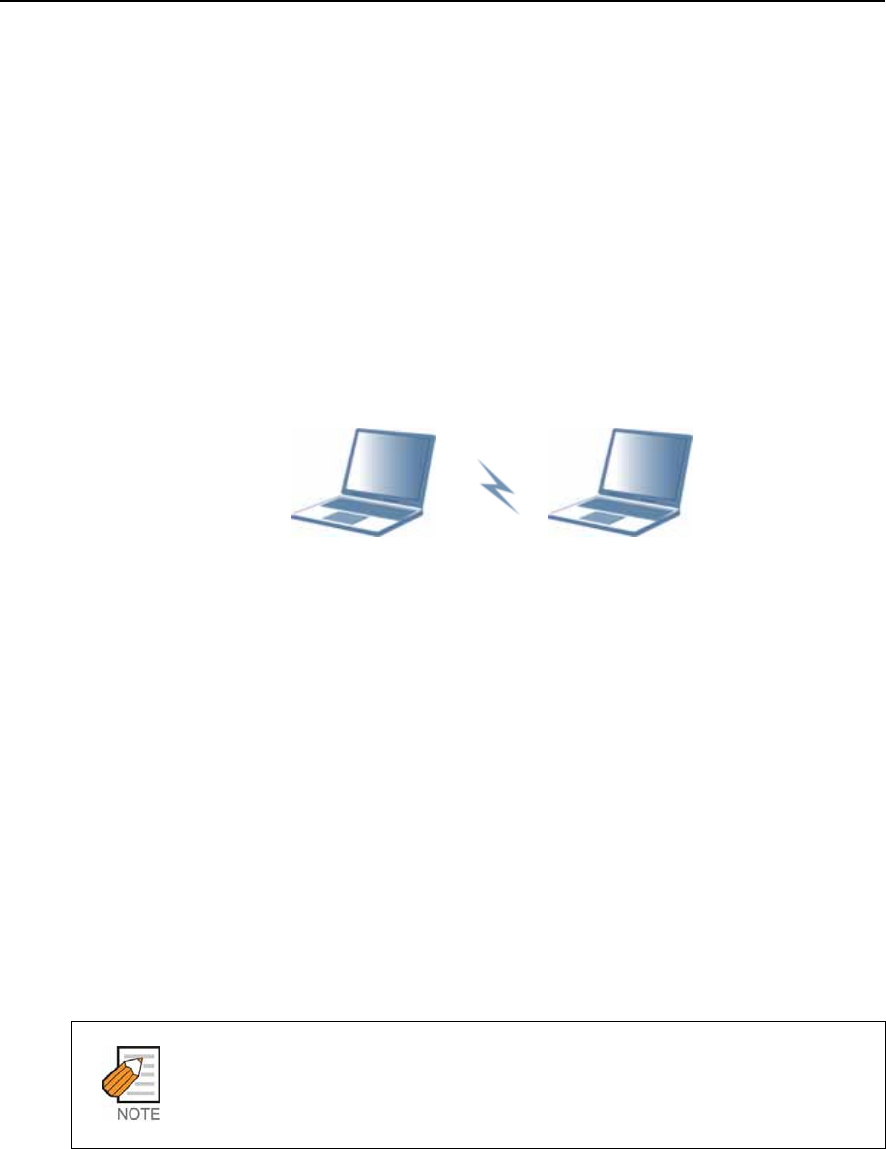
OfficeServ 500 Wireless LAN Service Manual/Ed.00 Annex A. WLAN(802.11b/DSSS) Specifications
© SAMSUNG Electronics Co., Ltd. Annex A-5
3.3 Data Link/Network Layer
The flexibility of network construction, a strength of wireless LAN is fully
considered in IEEE802.11 and is expressed in network models. Network models
defined in IEEE802.11 are categorized into an ad hoc network and Infra network.
Ad Hoc Network
The Ad hoc network consists of terminals only and is based on direct communication
between terminals. Its operation is to be recognized by Zone ID called BSS ID
logically. The Ad hoc network is suitable to collaborate through information sharing
or networks using wireless LAN where networks are not equipped.
Figure A.1 Data Link/Network Layer of WLAN-Ad hoc Network Model
Infra Network
Infra network is able to communicate with terminals that have at least one Access
Point(AP) and are within areas other than the areas of Infra network. The models of
the infra network has a Distribution System(DS), which serves as media.
DS is an abstract concept and is included in network models. It distributes the definition of
network as BSS ID.
Specifications do not describe the implementation method of distribution. However,
wireless LAN connected to the DS is called AP in the specifications. Management
protocols that operate wireless LAN using infra network are defined in many ways.
AP manages the operation of the zone and makes master and slave relationship
among terminals in the zone. For this, AP sends beacon to the operating zone.
It is impossible to send user data unless all terminals perform association to AP.
Beacon and Association
Beacon refers to sending code sending necessary information to wireless LAN.
Association means that terminals are connected to one AP.
User 1 User 2
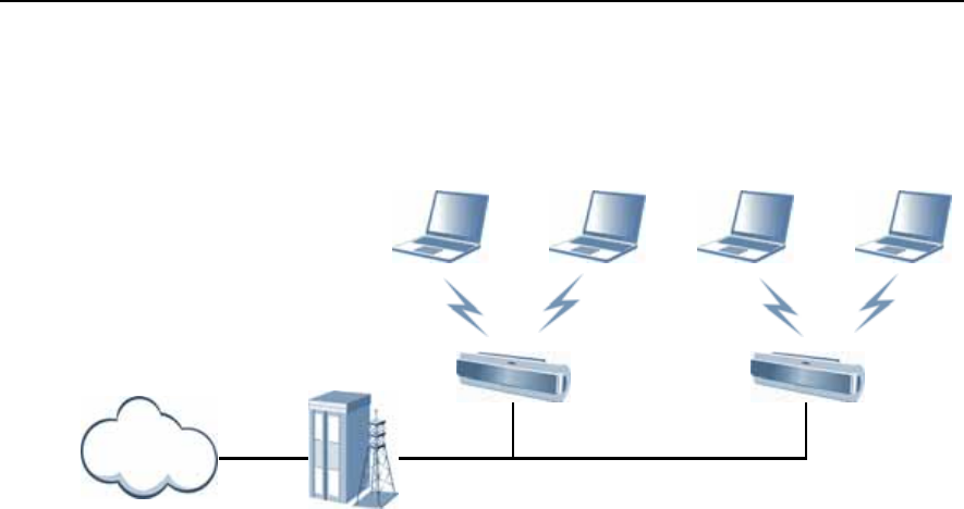
Annex A. WLAN(802.11b/DSSS) Specifications OfficeServ 500 Wireless LAN Service Manual/Ed.00
Annex A-6 © SAMSUNG Electronics Co., Ltd.
Wireless LAN provides terminal users with wireless communication services through
AP as shown in below figure.
Figure A.2 Data Link/Network Layer of WLAN-Infra Network Model
User1 User2 User3 User4
Server
Internet AP AP
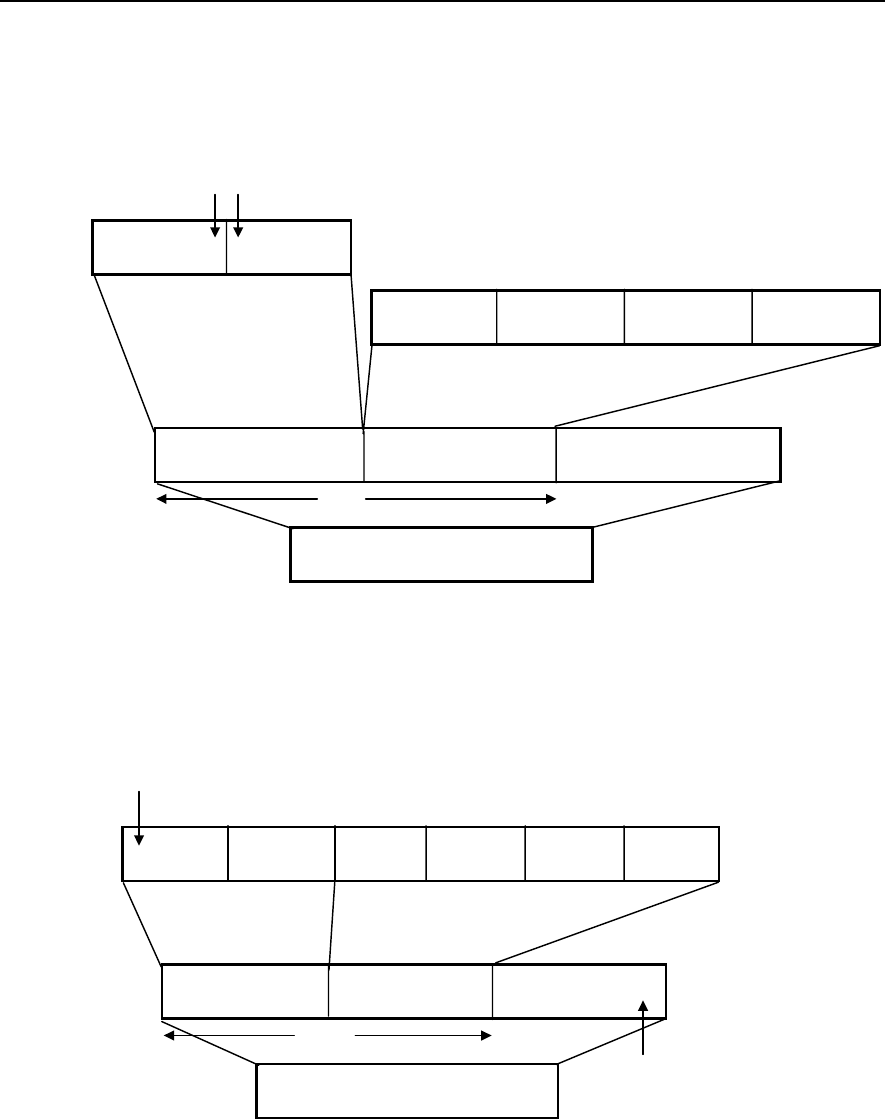
OfficeServ 500 Wireless LAN Service Manual/Ed.00 Annex A. WLAN(802.11b/DSSS) Specifications
© SAMSUNG Electronics Co., Ltd. Annex A-7
4 WLAN Frame Structure
4.1 Short PLCP PPDU Frame Format
Figure A.3 Short PLCP PPDU Frame Format of WLAN
4.2 Long PLCP PPDU Frame Format
Figure A.4 Long PLCP PPDU Frame Format of WLAN
SYNC
128 bits
SFD
16 bits
SIGNAL
8 bits
SERVICE
8 bits
LENGTH
16 bits
CRC
16 bits
PLCP Preamble
144 bits
PLCP Heade
r
48 bits PSDU
PPDU
1 Mbit/s D BPSK
192
μ
s
1 DBPSK
2 DQPSK
5.5 or 11Mbit/s
Scrambled One’s
ShortSYNC
58 bits
ShortSFD
16 bits
DBPSK SIGNAL
8 bits
SERVICE
8 bits
LENGTH
16 bits
CRC
16 bits
ShortPLCP Preamble
72 bits at 1 Mbit/s
ShortPLCP Heade
r
48 bits at 2 Mbit/s
PSDU
Variable at 2, 5.5 or 11 Mbit/s
PPDU
2 Mbit/s
96
μ
s
Scrambled Zero’s Backward SFD

Annex A. WLAN(802.11b/DSSS) Specifications OfficeServ 500 Wireless LAN Service Manual/Ed.00
Annex A-8 © SAMSUNG Electronics Co., Ltd.
5 Quality of Service (QoS)
QoS refers to the capability of networks that reduces the traffic volume of networks
or reserves some bandwidth. Network administrators provide their networks with
QoS in many ways. QoS does not mean 100% assurance of bandwidth or 0 % of
packet loss rate. However, QoS enables network administrators to send specific
traffic much faster or reserve network bandwidth. Network administrators can
manage the transmittance of traffic more efficiently than before.
QoS is the capability of networks that meets the service level of a specific application
of networks. The simplest QoS sends network traffic according to the priority of
transmittance and prior traffic is transmitted first.
6 Security
In wireless communication, data might leak or impersonation might be happen.
Therefore, MAC sub-layer is using encryption. Many Access Point(AP) products
have filtering function in the bridge or router of upper layer due to the MAC address
of the station.
According to IEEE802.11, encryption is made by combining 40 bits or 104 bits
button generated by 24 bits key and RC4 algorithm of RSA at each station. This is
called Wired Equivalent Privacy(WEP).
IEEE802.11 indicates that WLAN might be decoded due to long interception because
keys are fixed at stations. Therefore, the strict implementation of WEP is discussed in
IEEE802.11i. IEEE discusses procedures for authentication on wireless LAN and
Ethernet to prescribe them in IEEE802.1x standard.
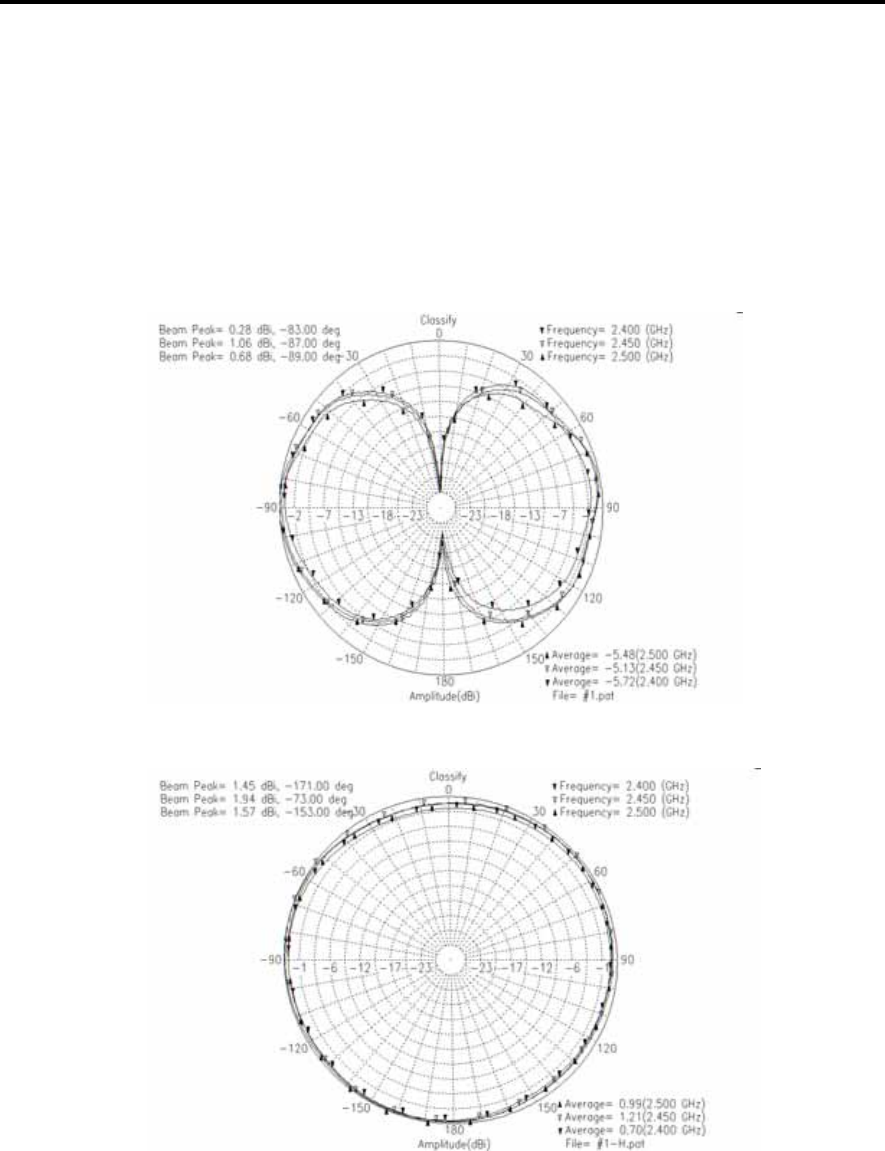
Annex B
© SAMSUNG Electronics Co., Ltd. Annex B-1
Antenna Beam Pattern of WBS24
This annex displays the beam pattern of WBS24 antenna in illustration.
Figure B.1 Beam Pattern of WBS24 Antenna

Annex B. Antenna Beam Pattern of WBS24 OfficeServ 500 Wireless LAN Service Manual/Ed.00
Annex B-2 © SAMSUNG Electronics Co., Ltd.
This page is intentionally left blank.

ABBREVIATION
© SAMSUNG Electronics Co., Ltd. Abbreviation-1
A
AP Access Point
B
BRI Basic Rate Interface
D
DSP Digital Signal Processor
DASL Digital Adapter for Subscriber Loops
DSSS Direct Sequence Spread Spectrum
E
ETSI European Telecommunications Standards Institute
F
FCC Federal Communication Commission
I
ISM Industrial Scientific and Medical
IP Internet Protocol
ISDN Integrated Services Digital Network
L
LED Light Emitting Diode
LAN Local Area Network
M
MAC Media Access Control
N
NIC Network Interface Card

Abbreviation OfficeServ 500 Wireless LAN Service Manual/Ed.00
Abbreviation-2 © SAMSUNG Electronics Co., Ltd.
P
PSAP Public Safety Answering Point
PHY Physical layer protocol
PCMCIA Personal Computer Memory Card International Association slot
PDA Personal Digital Assistant
PLL Phase Locked Loop
Q
QPSK Quadrature Phase Shift Keying
R
RF Radio Frequency
S
SDRAM Synchronous Dynamic Random Access Memory
SIP Session Initiation Protocol
U
USB Universal Serial Bus
UART Universal Asynchronous Receiver/Transmitter
UL Underwriters Laboratories
V
VoWLAN Voice Over WLAN
VOIP Voice Over Internet Protocol
W
WBS24 Wireless Base Station 2.4GHz
WiFi Wireless Fidelity
WIP-5000M Wireless IP-Phone 5000 Mobile type
WLI Wireless LAN Interface card
WLAN Wireless LAN

OfficeServ 500 Wireless LAN
Service Manual
©2003 Samsung Electronics Co., Ltd.
All rights reserved.
Information in this document is proprietary to SAMSUNG
Electronics Co., Ltd
No information contained here may be copied, translated,
transcribed or duplicated by any form without the prior written
consent of SAMSUNG.
Information in this document is subject to change without notice.
Visit us at
http://www.samsungnetwork.com