Samsung Electronics Co XE700T1A Nike Tablet User Manual Nike Tab eng indb
Samsung Electronics Co Ltd Nike Tablet Nike Tab eng indb
Contents
- 1. User Manual P1
- 2. User Manual P2
User Manual P2
1
2
3
4
5
User Guide
Getting Started
Using the Computer
Settings and Upgrade
Backup / Restore
Appendix
Contents
Start
62
63
Chapter 2.
Using the computer
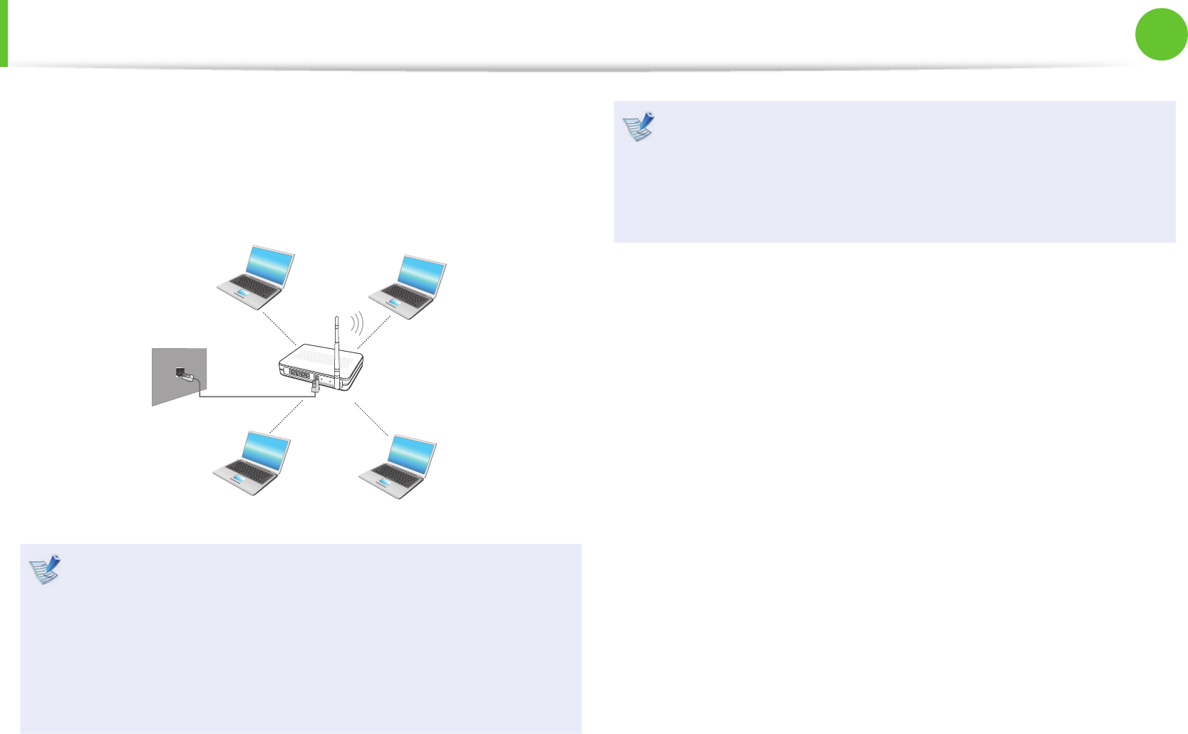
A wireless network (Wireless LAN) environment is a network
environment that enables communicating between multiple
computers at home or a small-size o ce through wireless LAN
devices.
The descriptions below are for computer models with •
a Wireless LAN card or device. A Wireless LAN device is
optional.
The pictures in this manual may di er from the actual
product depending on your wireless LAN device model.
If the wireless LAN is turned o , select • Easy Settings >
Wireless Network and set it to ON.
What is an Access Point ( AP)?
An AP is a network device that bridges wired and wireless LANs,
and corresponds to a wireless hub in a wired network. Connect
the computer with the wireless LAN function to the AP to use to
the network connection.
Wireless Network (Optional)
64
Chapter 2.
Using the computer
Wireless Network (Optional)
Connecting to a Wireless LAN
If there is an AP, you can connect to the Internet via the AP using
the Wireless LAN connection method provided by Windows.
These descriptions are written based on Windows 7, the latest
operating system. Therefore, some descriptions and gures
may di er from your operating system. But as the usage is
similar to other Windows operating systems, you can use
these descriptions for reference.
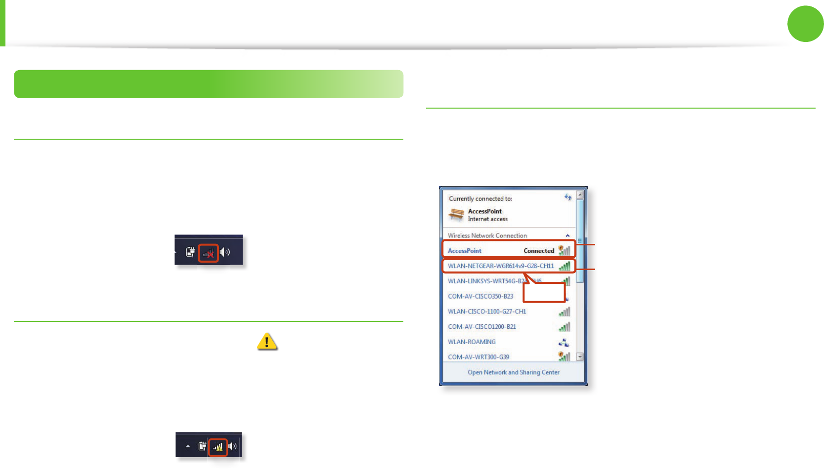
1 If you click the Network Connections icon in the system
tray, a list of available APs appears. If you select an AP to
connect to, the Connect button appears.
AP List
2 Click Connect.
If a network key is set for the AP, enter the network key and
then click Connect.
For the network key, please ask your network administrator.
3 When Connected to the AP is displayed, click the Close
button.
You can access the network.
64
65
Chapter 2.
Using the computer
Wireless Network (Optional)
Connecting to a Wireless LAN through Easy
Settings (Optional)
You can access a wireless LAN using Easy Settings.
These descriptions are for Windows 7 and for supported
models only.
1 Launch the Easy Settings.
2 Con gure the Wireless Network and set the Wi-Fi device to
ON.
If this option is set
to ON, the Wi-Fi
function will run.
AP List
z
x
c
Normal Wireless Network Status
If the wireless LAN icon is displayed in the system tray of the
Taskbar, it indicates that the computer is connected to the Internet
properly (see below).
66
Chapter 2.
Using the computer
Wireless Network (Optional)
Abnormal Wireless Network Status
When the wireless LAN is not connected
If the wireless LAN icon is displayed with an “X” in the system
tray of the Taskbar, it indicates that the wireless LAN device is
turned o or that there are no available APs. Or the wireless LAN is
disconnected.
When you are not connected to the Internet
This is indicated by the wireless LAN icon in the system tray of
the Taskbar. In this case, you have to check the IP address settings.
Please contact your network administrator and recon gure the IP
address.
When APs are found but your computer is not
connected to the Internet
This is the case when an AP with a weak signal has been set to
a high priority. Connect to an AP with a strong signal by clicking
it.
An AP with a strong signal strength
The currently connected AP.
The signal strength is low.
Click
66
67
Chapter 2.
Using the computer
Using the Slate PC Dock (Optional)
The Slate PC Dock supports various notebook computers so that
compatible peripherals can be connected to the computer.
You have to purchase the Slate PC Dock additionally.
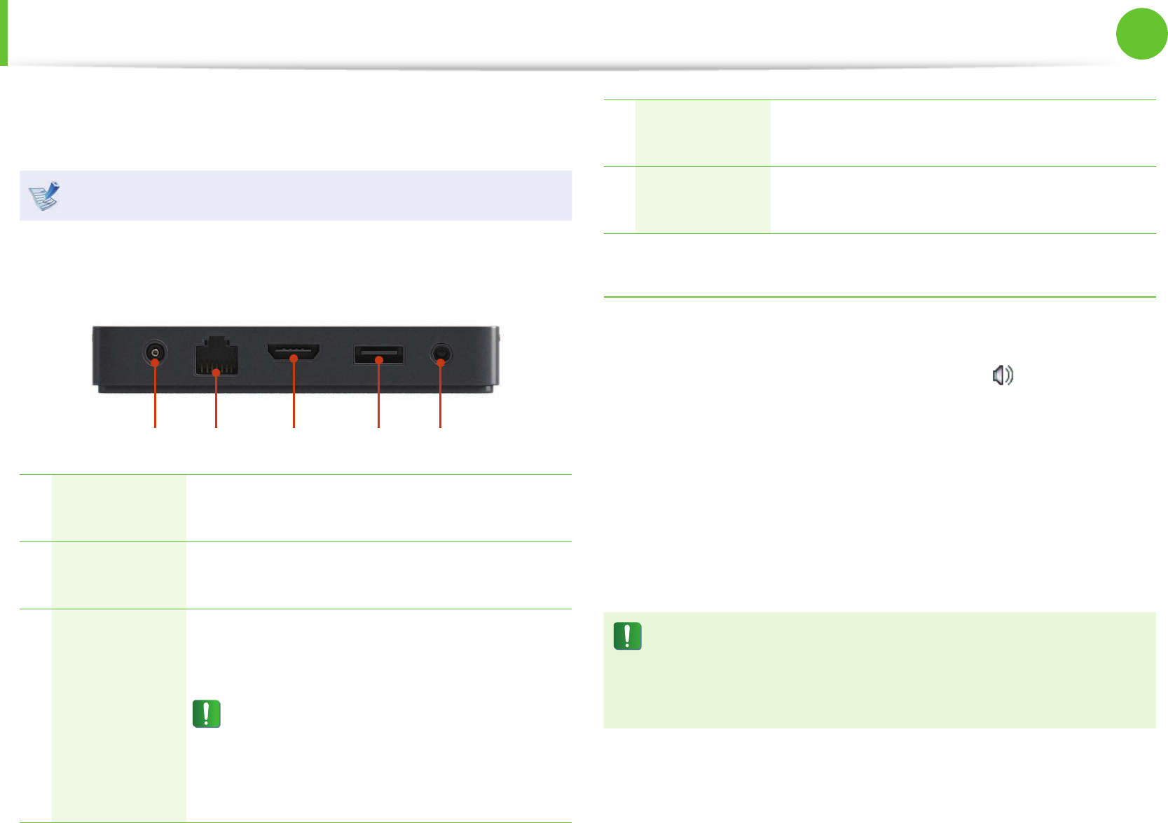
► Rear
1 2 3 4 5
1DC Jack A jack to connect the AC adapter that supplies
power to the computer.
2Wired LAN
Port Connect the Ethernet cable to this port.
3
Digital Video/
Audio Port
(HDMI)
(Optional)
You can connect an HDMI cable to this port.
Using this port, you can enjoy digital video
and audio on the TV.
You cannot use both this port and the
Micro HDMI port on the computer at the
same time.
To use the Micro HDMI port on the
computer, separate the Slate PC Dock.
4USB Port You can connect USB devices to the USB port
such as a keyboard/mouse, digital camera, etc.
5Headphone
Jack A jack used to connect the headphones.
Connecting and using a Headphone Jack
Using the Headphone jack
1 Right-click over the Volume Control icon in the
noti cation area at the bottom right of the Desktop and
select Playback Devices.
(Alternatively, click the Control Panel > Hardware and
Sound > Sound > Playback tab.)
2 Select the Speakers(USB audio), click Set Default and click
OK.
Restrictions
When the Slate PC Dock is connected to the computer, you
cannot use the microphone (USB audio) or the Line-In (USB
audio) item of the recording device.
68
Chapter 2.
Using the computer
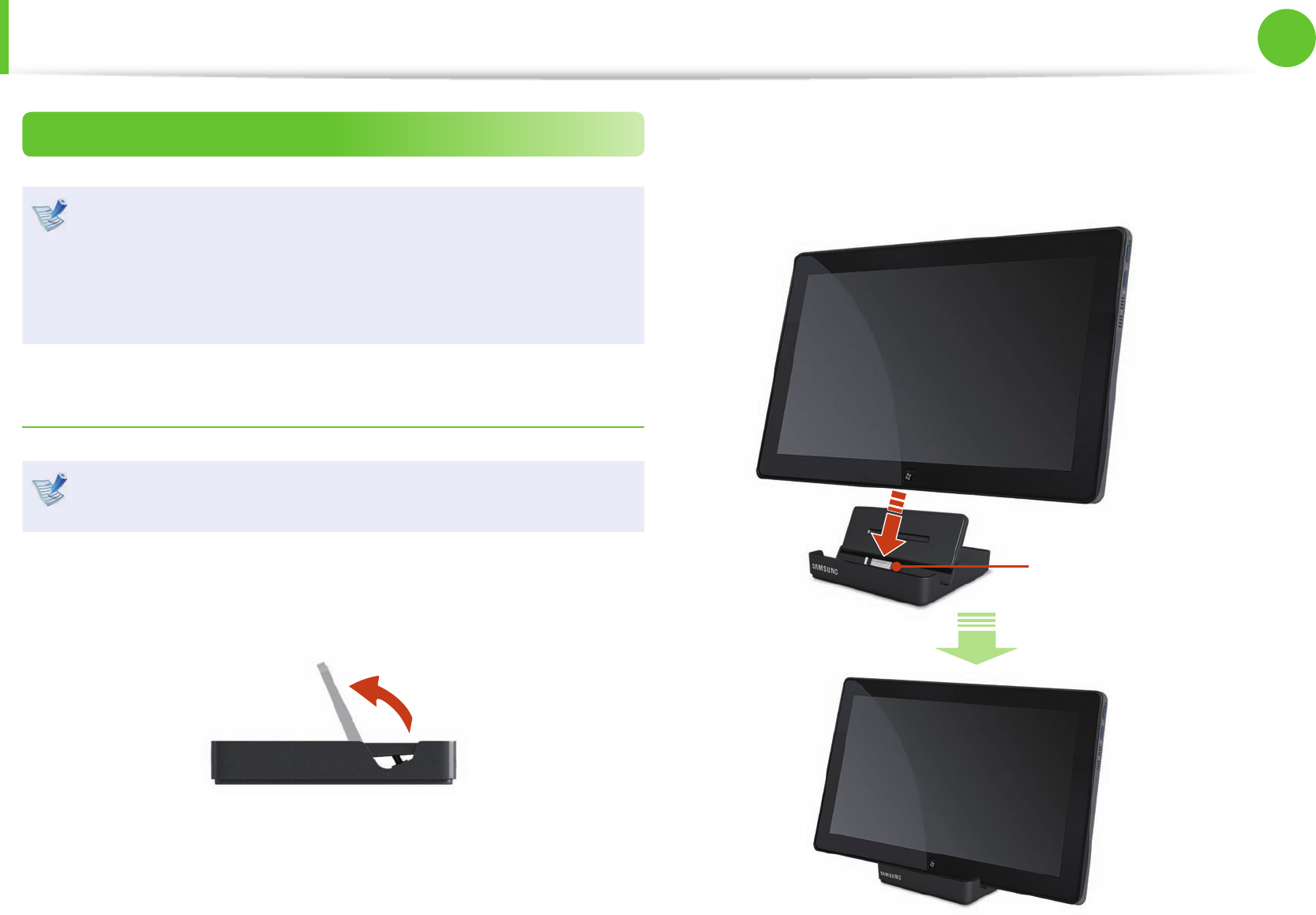
Installing/Removing
Before installing a computer to the docking station, make
sure to disconnect all the cables connected to the computer.
Although you can separate the computer from the Slate
PC Dock regardless of whether the computer is on or o ,
separating it when the computer is o is recommended.
Installing the computer
You can only use the Slate PC Dock with a Samsung computer
that supports this feature.
1 Insert your nger into the groove on the side of the Slate PC
Dock to open the top cover of the Slate PC Dock.
2 Align the computer connector of the Slate PC Dock and
the Slate PC Dock port at the bottom of the computer and
connect them.
Computer Connector
Using the Slate PC Dock (Optional)
68
69
Chapter 2.
Using the computer
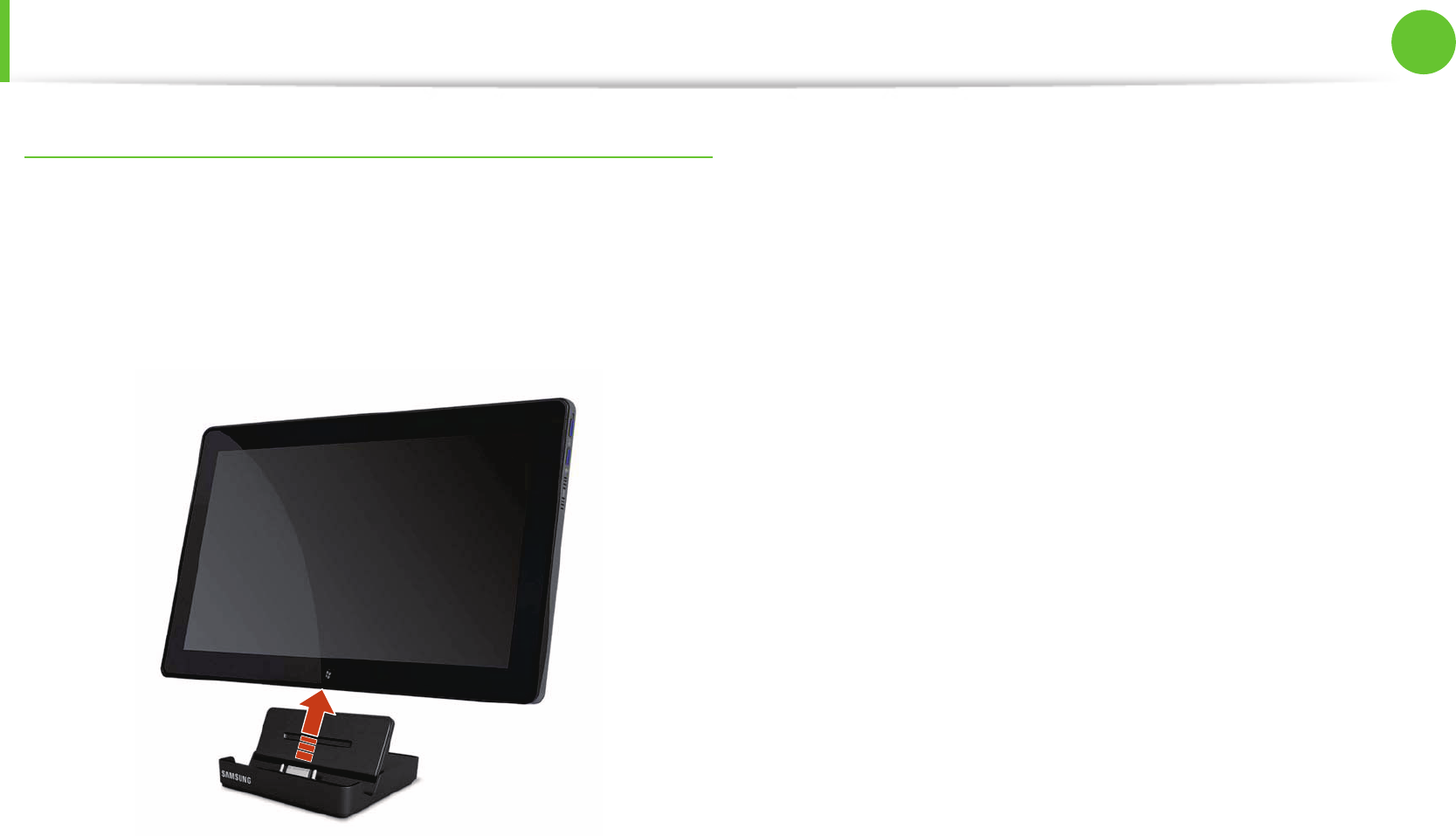
Separating the Computer
1 Turn the computer o.
2 Pull the computer upward by hand while holding the Slate PC
Dock rmly with the other hand.
Using the Slate PC Dock (Optional)

LCD Brightness Control 71
Easy Settings (Optional) 73
BIOS Setup 74
Changing the Boot Priority 76
Battery 77
Chapter 3.
Settings and Upgrade
71
Chapter 3.
Settings and Upgrade
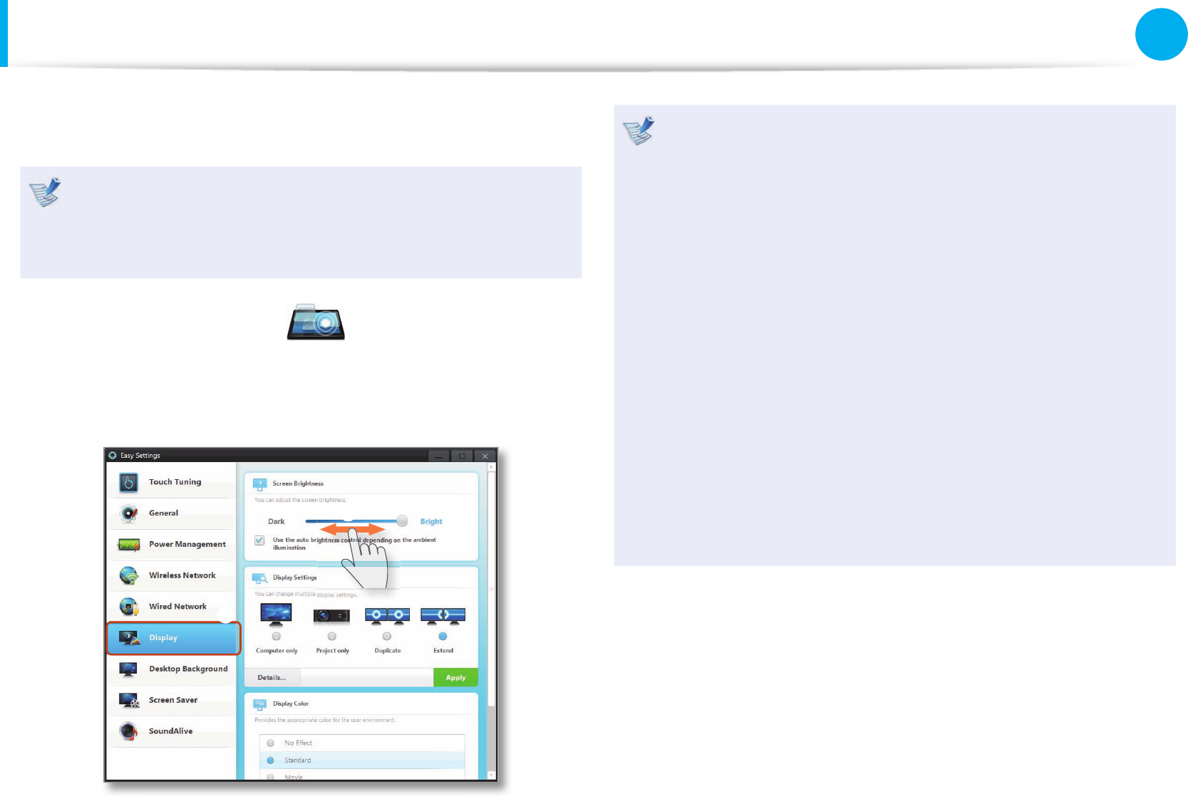
LCD Brightness Control
Using the Easy Settings, you can control the LCD brightness.
The screen brightness is automatically set to the brightest
level when AC power is connected and the brightness is
automatically set dimmer when the computer runs on battery
power to extend the battery use time.
1 Launch the Easy Settings .
2 Click Display > Screen Brightness and set the brightness
level.
z
x
Maintaining the changed LCD brightness even after •
turning the computer on again
To maintain the LCD brightness set by using the brightness
control keys or through the Power Options, follow the
procedures below.
► For Windows 7
1. Click Control Panel > Hardware and Sound > Power
Options.
2. Click Change the settings of the currently con gured
mode.
3. Adjust the display brightness adjustment menu bar and
click the Save the changes button.
Saving battery power consumption•
Decreases the LCD brightness when the computer
is running on battery power to save battery power
consumption.

72
Chapter 3.
Settings and Upgrade
LCD Brightness Control
LCD bad pixels principle of computer•
Samsung observes the speci cations regarding strict
quality and reliability of LCD. But in spite of that, it is
inevitable that there might be a small number of bad
pixels. A large number of bad pixels can cause problems in
appearance, but a small number of pixels doesn’t a ect the
computer performance.
Therefore Samsung observes and manages the following
dot principles:
- Bright dot : 2 or less
- Black dot : 4 or less
- Combination of Bright and Dark : 4 or less
Instructions for Cleaning the LCD
Clean the LCD panel with a soft cloth lightly moistened with
computer cleansing detergent moving in one direction.
Cleaning the LCD panel with excessive force can damage the
LCD.
72
73
Chapter 3.
Settings and Upgrade
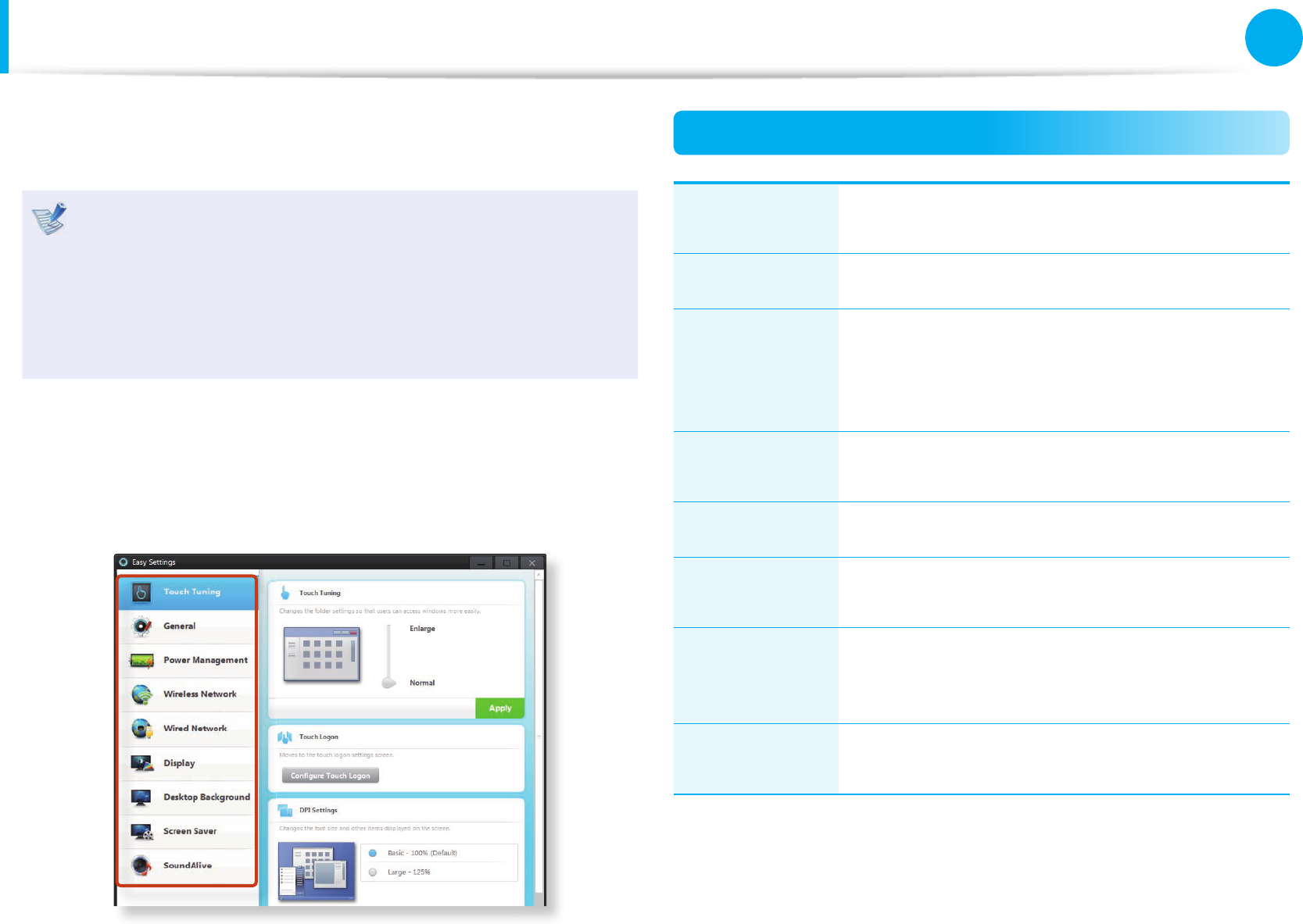
Easy Settings (Optional)
Easy Settings is the integrated Samsung software control program
that allows you to con gure various settings.
This description is for models that support the function •
and are running on Windows 7.
The screen gures and terms may di er depending on the •
model.
Depending on the program version, some functions may •
not be provided or di erent functions may be provided.
1 Launch the Easy Settings.
2 You can con gure a function by selecting an item in the
System Controller.
Functions
Touch
calibration
The Touch Logon setting and the screen text
font size setting.
General Fast Start setting, silent mode and user account.
Power
Management
You can con gure the Power Plan (high-
performance, power-saving, Samsung optimal
mode), the power-saving settings and the
display settings.
Wireless
Network
You can con gure whether to use the Airplane
mode and Wi-Fi options.
Wired Network You can select automatic or xed IP settings.
Display You can con gure external display devices, and
the screen brightness/color.
Desktop
Background /
Screen Saver
You can con gure the Desktop background and
the screen saver.
SoundAlive You can con gure the sound mode (Music,
Movie, Speech, Silver Mode etc.).

74
Chapter 3.
Settings and Upgrade
BIOS Setup
The BIOS Setup enables you to con gure your computer hardware
according to your needs.
Use the BIOS setup to de ne a boot password, change the •
booting priority, or add a new device.
Since incorrect settings may cause your system to •
malfunction or crash, take care when con guring the BIOS.
The functions of the BIOS setup are subject to change for •
product function enhancement purposes.
The BIOS Setup menus and items may di er depending on •
your computer model.
Entering the BIOS Setup
1 Turn the computer on and press and hold the Home button
for 4 seconds before the screen is displayed on the touch
screen.
2 After a moment, the BIOS setup screen appears.
The items in the BIOS setup may di er depending on the
product.
74
75
Chapter 3.
Settings and Upgrade
The BIOS Setup Screen
The BIOS Setup menus and items may di er depending on
your computer model.
Aptio Setup Utility - Copyright (C) 201x American Megetrends, Inc.
SAMSUNG Electronics BIOS Team ux.x cx.xx.xxxx
System Time [09:07:06]
System Date [Fri 07/08/2011]
SATA Port 1 SAMSUNG xxxxxxxxxxxx-00000
CUU Vendor Intel(R)
CPU Type Core(TM) ix-xxxxM CPU
CPU Speed x.xx GHz
CPU VT (VT-x) Supported
Total Memory xxxx MB
BIOS Version FWx.Vxxx.xxxxxxxx.SSH
MICOM Version xxFW.Vxxx
Set the Time.
To modify the time, press
'Enter' key. And then use
'Tab' to switch between Time
elements.
,+[R,L&V,D/V,U]: Select Screen
)*[V,U/V,D]: Select Item
Enter [R,L]: Select >> Sub-Menu
F5/F6: Change Help
F1 : General Help
F3 : Previous Values
F9 : Optimized Defaults
F10 : Save and Reset
ESC [Home]: Exit
R,L = Rotation Lock
V,U/D = Volume Up/Down
Home = Home Button
SysInfo Advanced Boot Exit
Setup Menu
Setup Items
Help
Help for the
selected
item appears
automatically.
Setup Menu Description
SysInfo This is a description about the basic speci cations
of the computer.
Advanced Using this menu, you can con gure the major
chipsets and additional functions.
Boot This menu enables you to con gure peripherals and
booting related settings such as the boot priority.
Exit Used to exit the Setup either saving the changes or
not.
Buttons for BIOS Setup
Volume Control
buttons
Press the Volume Control buttons to move
the focus upward or downward.
Lock Screen
Rotation + Volume
Control button
combination
Press the Lock Screen Rotation button
and the Volume Control button
simultaneously to move the focus to the
left or right.
Home button Press this button to return to a higher-level
menu or to move to the Exit menu.
Lock Screen
Rotation button
Press this button to select an item or enter
the sub menu.
BIOS Setup

76
Chapter 3.
Settings and Upgrade
Changing the Boot Priority
The computer is con gured so that it boots from the SATA HDD
with priority, by default.
The following describes how to change the boot priority so that
the computer boots from the USB CD drive with priority.
The screen images and terms may di er from actual product
depending on the computer model and driver version.
1 Select the Boot menu in the BIOS Setup.
2 In the Boot Device Priority eld, press the Lock Screen
Rotation button.
ඖ Boot Device Priority
ඖ TPM Configuration
PXE OPROM [Disabled]
Smart Battery Calibration
3 Press the Volume Control button to move the focus to the
USB CD item and press the Lock Screen Rotation button to
move the USB CD item to the top.
Set Boot Priority
1. SATA HDD : XXXXX
2. USB KEY : N/A
3. USB CD : XXXXXXXX
4. USB FDD : N/A
5. USB HDD : N/A
6. NETWORK : N/A
4 Press the Home button to return to a higher-level menu.
5 Move to the Exit menu and select Save Changes and Reset.
6 The computer will be restarted.
Now, the boot priority has been changed so that the
computer boots from the USB CD drive with priority.
76
77
Chapter 3.
Settings and Upgrade
Battery
Please refer to the following instructions when running the
computer on battery power without connecting the AC power.
This computer is equipped with an internal battery.
Precautions
Users cannot remove or replace the internal battery. •
To remove or replace the battery, use an authorized •
service center in order to protect the product and
users. You will be charged for this service.
Use only chargers speci ed in the User Manual.•
Never heat the battery pack, put it near or in a re or use at •
a temperature higher than 60°C, as this may cause re.
Please refer to the system operation environment of •
this manual and operate and store the battery at room
temperature.
Before using the computer for the rst time, make sure to •
connect the AC adapter and charge the battery completely.
The images used for the illustration are of a representative •
model, therefore the images may di er from the the actual
product.
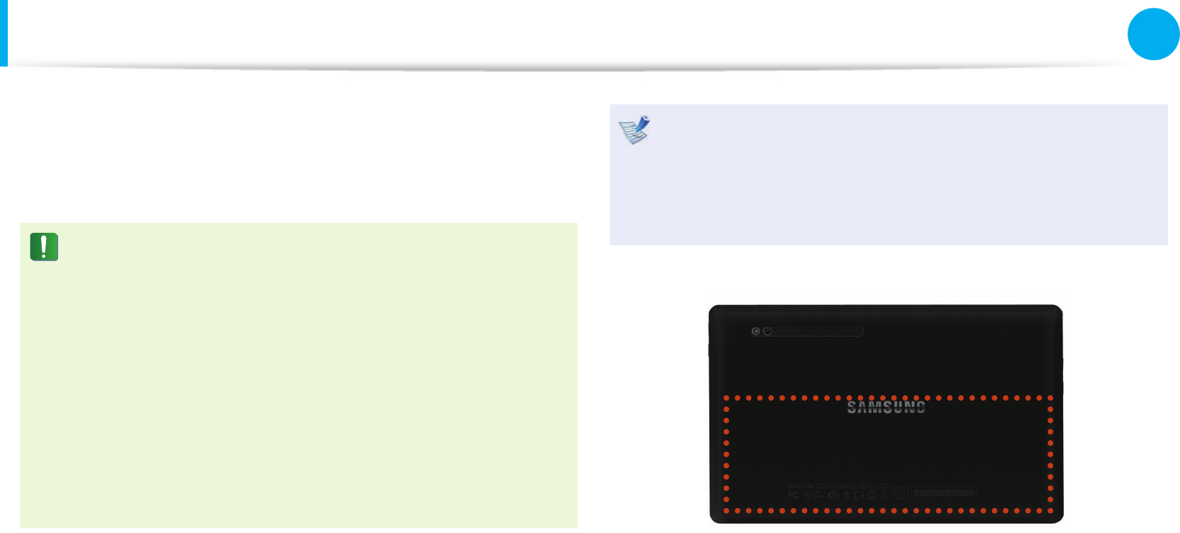
The location of the internal battery
78
Chapter 3.
Settings and Upgrade
Battery
Charging the Battery
An internal battery is embedded. Connect the AC adapter to the
power input jack of the computer. The battery will start charging.
Measuring the Remaining Battery Charge
You can view the battery charge status by completing the
following procedures.
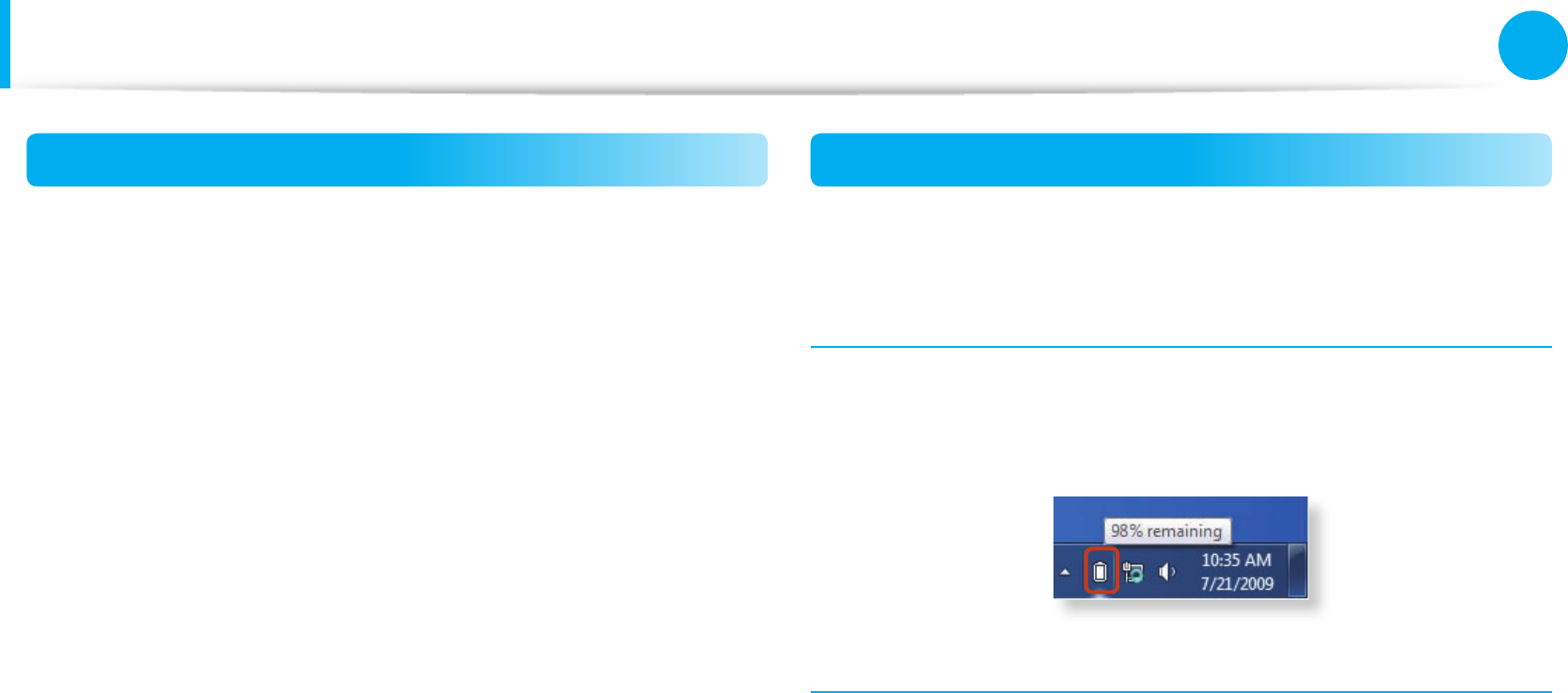
Con rming the battery charge in the Taskbar
Disconnect the AC adapter and move the mouse cursor over
the battery icon in the system tray of the Taskbar to con rm the
remaining battery charge.
Battery Usage Time Information
A battery is an expendable supply, so when using it over a long
time, the capacity/battery life is shortened. If the battery life is
reduced to under half of its initial time, we recommend purchasing
a new battery.
When not using the battery for a long time, store the battery after
charging it to 30-40% of its capacity. This extends the battery life
time.
78
79
Chapter 3.
Settings and Upgrade
Battery
Extending the Battery Usage Time
Decreasing the LCD Brightness
If you dim the screen brightness in the Easy Settings > Display >
Screen Brightness, you can extend the battery use time.
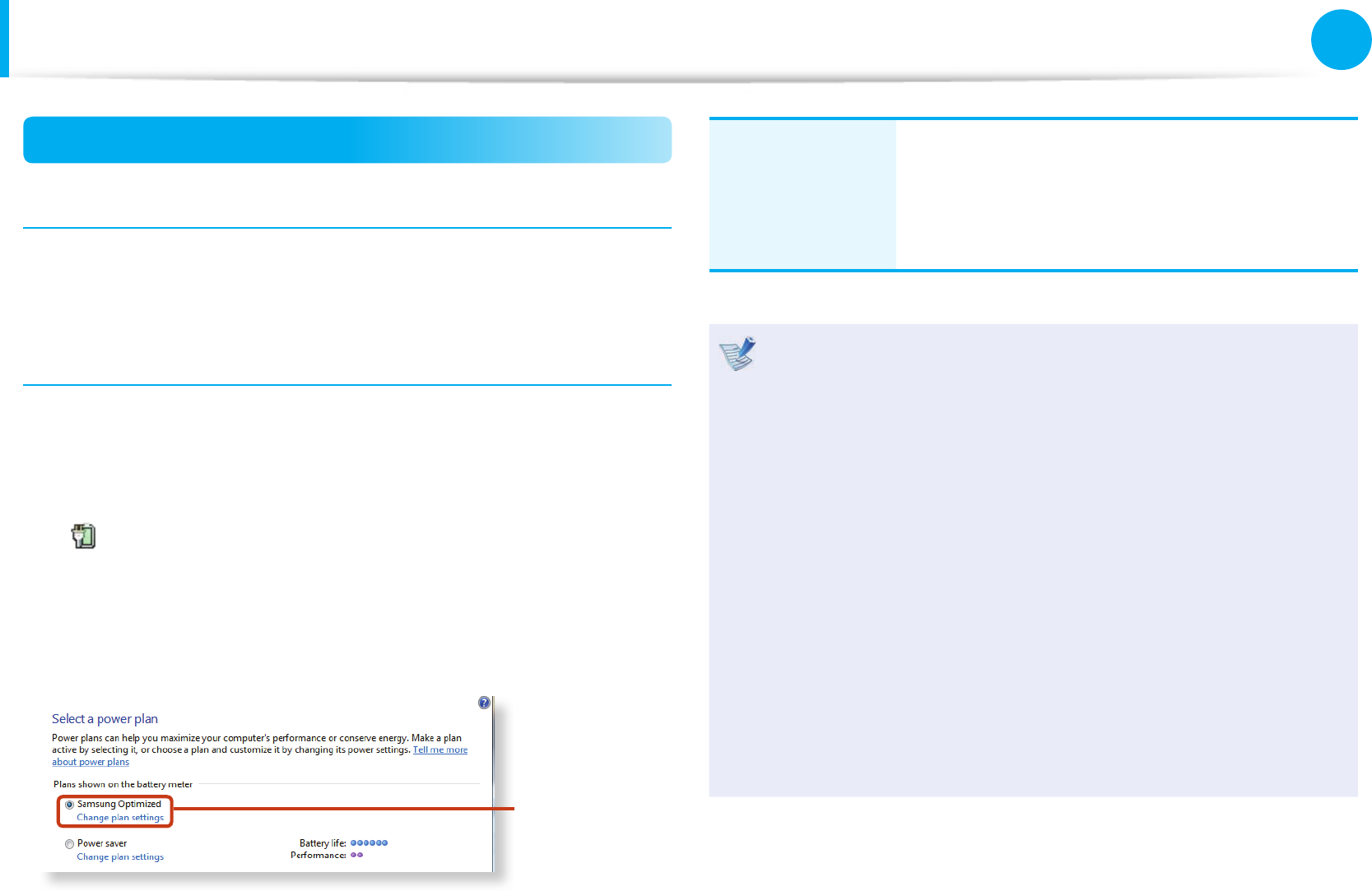
Using the power management program
1 Click Start > Control Panel > Hardware and Sound >
Power Options.
Alternatively, right-click the power measuring device icon
in the noti cation area of the taskbar and select Power
Options.
2 If the following screen appears, select one of the modes.
Samsung
Optimized
Samsung
Optimized
This mode is appropriate for normal conditions.
It maximizes the system performance when
the computer is running on AC power while
maximizing the battery usage time when the
computer is running on battery power.
What is the Power-saving E ect?•
This product displays the battery life in each power mode.
The higher the power saving e ect increases, the longer
the graph bar is displayed.
When Using Games or Multimedia•
The system may not operate properly in maximum battery
mode. It is recommended to connect the AC adapter to the
system or to use the system in general mode.
Usage Mode of Samsung Battery Manager•
- The maximum battery mode optimizes the system
operation speed to increase the battery run time, so the
program execution time may get longer.
- If you change the power settings, the properties in Power
Options window will also be changed.

80
Chapter 3.
Settings and Upgrade
Battery
Extending the Battery Life (Optional)
In the Easy Settings program, click System Controller > General
and set the Battery Life Extender to ON or OFF.
OFF
This mode maintains 100% of the battery charge
when using the computer on AC power. In this case,
although the battery use time increases, the battery
life is reduced.
ON
This mode maintains 80% of the battery charge
when using the computer on AC power. In this
case, although the battery use time decreases, the
battery life is extended.
Alternatively, to extend the battery life
Press the F2 key when the Samsung logo appears in the
booting sequence to enter the BIOS Setup, select Advanced
> Battery Life Cycle Extension, and set it to Enable.
Then you can use the battery life cycle extension mode.
Using the Battery Calibration Function
When charging/discharging the battery repeatedly for a short time
only, the battery usage time may be reduced by the di erence
between the actual battery charge and the remaining charge
display.
In this case, the actual battery charge and the remaining charge
display will be the same by discharging the battery completely
using the Battery Calibration function, and then recharging it
again.
The screen images and terms may di er from actual product
depending on the computer model and driver version.
1 Disconnect the AC power adapter after turning o the
computer.
2 Turn the computer on again and press and hold the Home
button for 4 seconds to enter the BIOS Setup.

80
81
Chapter 3.
Settings and Upgrade
Battery
3 Move to the Boot > Smart Battery Calibration item using
the direction keys and press <Enter>.
ඖ Boot Device Priority
ඖ TPM Configuration
PXE OPROM [Disabled]
Smart Battery Calibration
4 When the Yes item of the Battery Calibration Con rmation
window is selected, press the Lock Screen Rotation button.
The Battery Calibration process will proceed. To stop the
process, press the Home button.
This operation requires 3~5 hours depending on the battery
capacity and the remaining battery charge.

Chapter 4.
Backup / Restore
Samsung Recovery Solution (Optional) 83

83
Chapter 4.
Backup / Restore
Samsung Recovery Solution (Optional)
Samsung Recovery Solution is a program that enables restoring
or backing up the hard disk drive for when a problem occurs with
the computer.
If the computer fails to boot up, you can restore the computer by
pressing the F4 key in the booting screen.
To use the hot keys, you have to use a keyboard. Please •
connect a keyboard (optional).
Samsung Recovery Solution may not be provided or the •
version may di er depending on the model. In addition,
some functions may not be provided or may di er
depending on the version.
For more information on using Samsung Recovery
Solution, please refer to the online help of the program.
The screen images in this document may di er from actual •
product.
If your computer does not have an internal ODD, you need •
an external ODD connected to your computer to use the
Backup Function or Restore Function using DVDs.
The System Software function may not be provided •
depending on the program version.
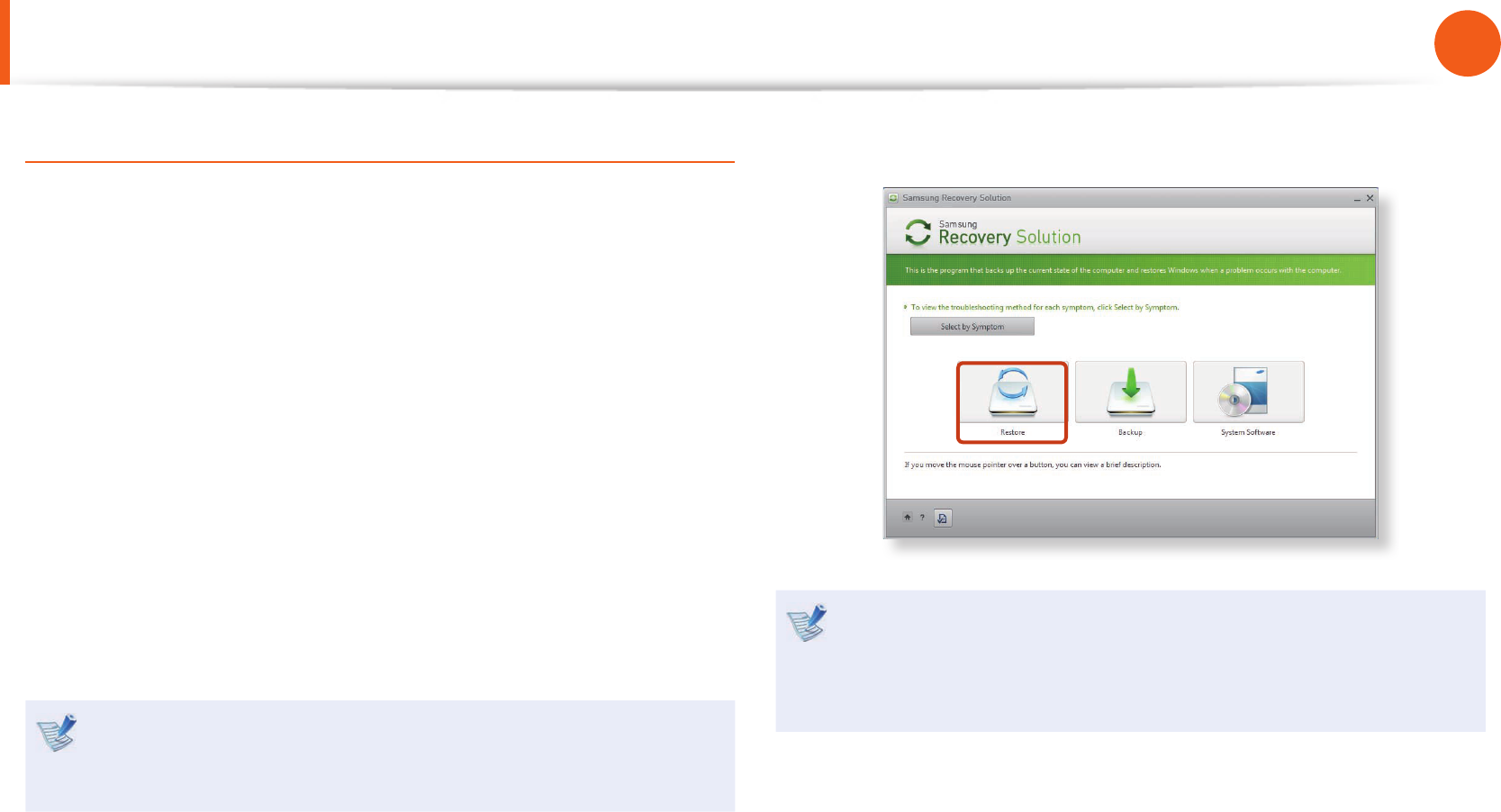
Samsung Recovery Solution Functions
Backup/Restore Functions
Backup Function
Backs up drive C or required folders and les.
Complete Backup•
Backs up drive C.
Data Backup•
Backs up important folders and les.
A problem
occurs
V I R U S
Restore Function
Restores major Windows les, drive C, or
folders and les to the previous state.
Basic Restore•
Restores only major Windows les in a short
time.
Complete Restore•
Restores drive C to the previous, normal
state.
Data Restore•
Restores important les or folders to the
previously backed up state.

84
Chapter 4.
Backup / Restore
System Software Functions
Samsung Recovery Solution provides system software so that
you can reinstall or copy the device drivers and system software
necessary for normal operations onto a separate storage device.
Restore Function
Not only can you use Samsung Recovery Solution when Windows
is running, but also when you are unable to boot up into Windows.
Let’s learn how to use Samsung Recovery Solution.
Optional functions such as Initial State Image, Initial Status Backup,
and Partitioning are only available in some models.
If the image of the initial state is saved on a DVD or removable
storage device, connect the DVD drive or removable storage
device to the computer before using the function.
Partition Setup & Initial Status Backup
If you turn your computer on for the rst time, the Initial Status
Backup function is performed after registering Windows. This
function saves an image of the Initial Status of the C drive to a
secure location so that users can restore the computer to the
Initial Status using the Complete Restore function. An Initial Status
Backup is only performed once immediately after the computer is
purchased.
1 If you turn the power on for the rst time, the Register
Windows screen appears. If you register Windows according
to the instructions on the screen, the computer will be
restarted.
2 After the computer has been restarted, the Partition Setup
screen appears.
To resize the C and D drives, adjust the partition size using
the slide bar and the click Next.
The Partition Setup function is only available when the
computer is turned on for the rst time and will not
be available afterwards. Once you have completed the
partitioning, it cannot be resized. Partition the disk carefully.
3 The Initial Status Backup screen appears.
To continue the Initial Status Backup, click Restart Now. The
computer will restart.
4 The Initial Status Backup is performed to backup the initial
status of the C drive to a secure location. This backup image
is used for the Complete Restore function that restores your
computer to the initial status.
5 When the Initial Status Backup is complete, restart Windows.
Samsung Recovery Solution (Optional)
84
85
Chapter 4.
Backup / Restore
Restoring the computer
Restore is a function that enables restoring the computer to a
saved point when the computer was purchased or a user-saved
point.
The Restore function provides the Basic Restore and Complete
Restore options.
1 – When Windows is running:
Click Samsung Recovery Solution.
– When Windows does not start:
Turn the computer on and press the F4 key when the boot
screen (SAMSUNG logo) appears. After a moment, the
computer boots up in Restoration mode and the Samsung
Recovery Solution screen appears.
In touch-screen models, the touch screen function does not
work in recovery mode. In this case, please use the touchpad,
mouse or keyboard.
2 If the initial menu screen appears, click Restore.
If you click Select by Symptom, the Select by Symptom
menu appears. If you select a symptom, a recommended
restoration option will blink. Click the restoration option to
continue.
Samsung Recovery Solution (Optional)
86
Chapter 4.
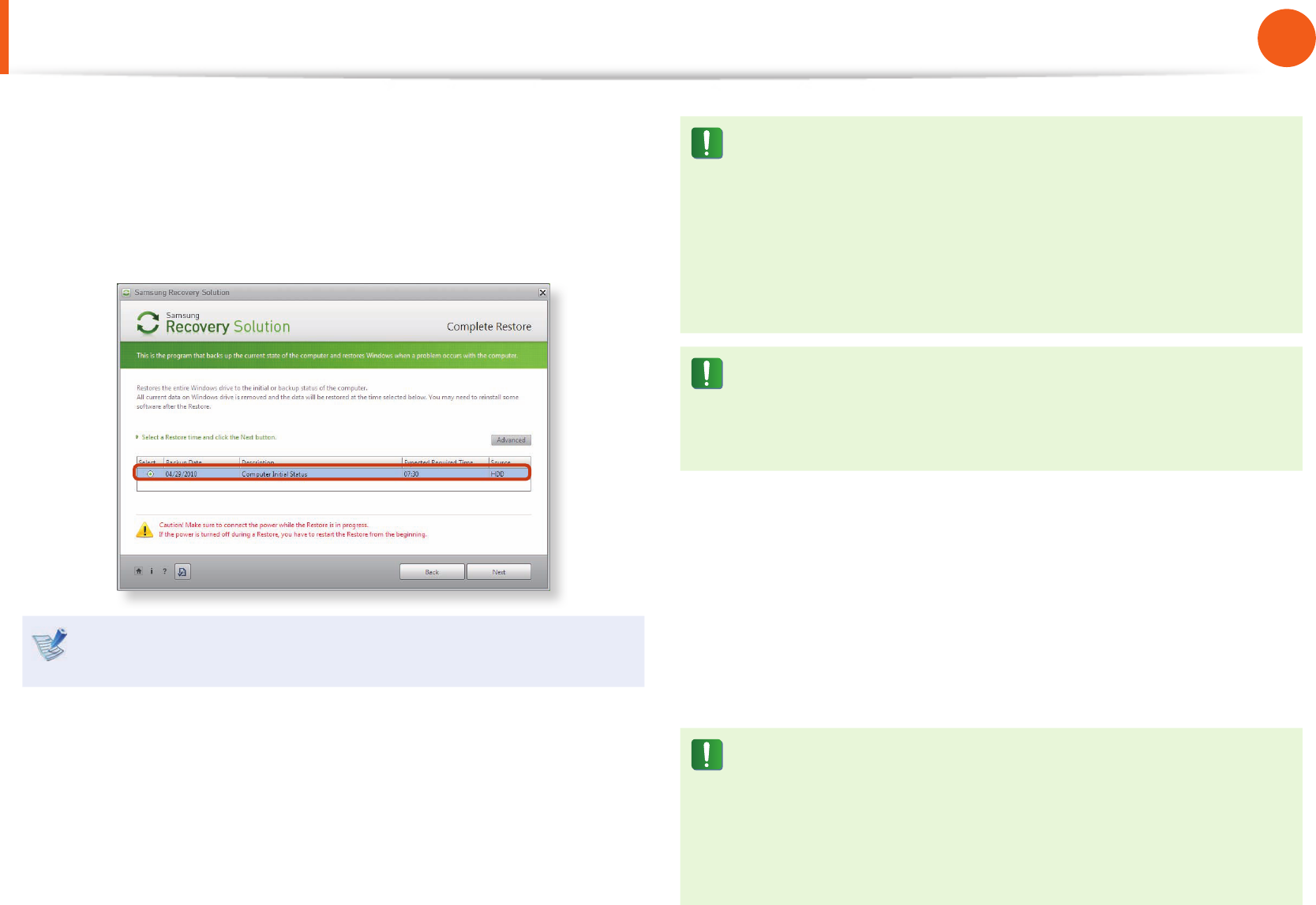
Backup / Restore
3 Select either Basic Restore or Complete Restore from the
Restore menu.
To restore the computer to the initial state, click Computer
Initial State and perform the restoration process according
to the instructions that appear on the screen.
Run Complete Restore if the computer does not work even
after Basic Restore has been completed.
In the Advanced menu, you can change the size of the hard
drive partitions (e.g. C: and D:).
Make sure to backup your data in advance, as all data will •
be deleted after the partition size is changed.
The • Advanced menu is only activated when the computer
boots up in the restoration area.
(by pressing the F4 key during the booting sequence.)
Since a Complete Restore deletes all user data as well
as additionally installed programs, please backup your
important data rst using the Data Backup function, before
running Complete Restore.
4 The computer boots up into restoration mode and the
restoration progress message appears. If you click OK, the
restoration begins. The restoration may take some time,
please wait for a moment.
5 When the ‘Restart the System’ message appears after the
restoration is complete, click OK to restart the system.
Make sure that the power cord is connected while the
restoration is in process. The rst time the computer boots
up after a Complete Restore has been performed, the speed
of the boot process may be slowed down due to the system
optimization process. At this time, do not shut the computer
down by force.
Samsung Recovery Solution (Optional)
86
87
Chapter 4.
Backup / Restore
Complete Backup/Restore
A Complete Backup saves the complete image of the C drive
onto another drive or DVD. A Complete Restore restores the
image le saved by the Complete Backup onto the C drive.
Complete Backup
If you perform the Complete Backup function onto a DVD or
removable storage device, you can restore your computer
even when a problem occurs with the hard disk or when the
restoration area is removed.
To create a backup, a removable storage device with at least
15 GB of free space is required.
1 Click Backup in the start screen of the Samsung Recovery
Solution.
2 Enter a description of the current status of the computer and
click Next.
After connecting a DVD drive or removable storage device,
you can specify the DVD drive or removable storage device
as the Save Path.
Select Drive D. Select the DVD drive.
3 When the option selection item appears, select an option
and click Next.
The LiveImaging and System Software Backup functions are
supported as options for the Complete Backup operation.
LiveImaging:• Performs the Complete Backup operation
while Windows is running. The backup operation using
LiveImaging may slow down if the hard disk drive is
accessed frequently by other applications.
System Software Backup: • This function backs up the
system software on to the DVD after the completion of the
Complete Backup operation.
Samsung Recovery Solution (Optional)
88
Chapter 4.
Backup / Restore
4 When the system restarts in Restoration Mode, the Complete
Backup operation begins. Continue with the backup by
following the instructions.
Samsung Recovery Solution supports the DVD+R, DVD-R, •
DVD+RW and DVD-RW formats.
If the LiveImaging option has been selected, the Complete •
Backup operation begins without the computer being
restarted.
5 Continue with the Complete Backup operation by following
the instructions.
6 When the ‘Restart the System’ message appears after the
backup is complete, click OK to restart the system.
If the LiveImaging option has been selected, the computer is
not restarted.
Samsung Recovery Solution (Optional)
88
89
Chapter 4.
Backup / Restore
Complete Restore
1 – When backing up onto DVD
Turn the computer on and insert the backup DVD into the
DVD drive.
If there are multiple backup DVDs, insert the rst DVD.
– When backing up to a removable storage device
Connect the removable storage device.
– When backing up to another drive
Proceed to Step 2.
2 When the Samsung Recovery Solution start screen appears,
click Restore and then click Complete Restore.
3 Select a Complete Backup restoration point in the
restoration point selection screen and click the Next button.
The system is restarted.
4 The restoration progress message appears after the computer
boots up in restoration mode. If you click OK, the restoration
begins.
If multiple DVDs have been used for a Complete Backup,
whenever burning a DVD is completed, the “Insert the next
DVD” message will appear.
5 When the ‘Restart the System’ message appears after the
restoration is complete, click OK to restart the system. The
Complete Restore has been completed.
Samsung Recovery Solution (Optional)
90
Chapter 4.
Backup / Restore
Data Backup/Restore
The Data Backup function enables you to backup speci c les
and folders to another drive, DVD or removable storage device.
Data Restore enables you to restore data using the data saved by
a Data Backup when data is lost. This guide describes the Backup
and Restore procedures on the basis of backing up and restoring
by using DVD.
Data Backup
1 When the Samsung Recovery Solution start screen appears,
click Backup and then click Data Backup.
2 In the data selection screen, select either Basic Selection or
Select from all, select a folder or le to be backed up, and
then click the Next button.
3 Enter a description for the backup in the Description eld
so that you can easily recognize it later and specify the Save
Path.
If your computer has a DVD-Writer, you can specify the DVD
drive as the Save Path.
Select Drive D. Select the DVD drive.
If you have speci ed a hard disk drive or a removable disk as
the Save Path, the SamsungRecovery\SamsungData folder
is created on the corresponding drive (e.g. D:\) and the data
is saved to the folder. Take care to not delete the folder by
mistake or on purpose.
4 If you click the Next button, the Data Backup begins. If you
have selected the DVD drive as the Save Path, the “Insert a
blank DVD” message appears. Insert a blank DVD and click
the OK button.
5 The “Backup is completed” message appears.
Samsung Recovery Solution (Optional)

90
91
Chapter 4.
Backup / Restore
Data Restore
1 – When backing up onto DVD
Turn the computer on and insert the backup DVD into the
DVD drive.
– When backing up to a removable storage device
Connect the removable storage device.
– When backing up to another drive
Proceed to Step 2.
2 When the initial menu screen appears, click Restore and then
click Data Restore.
3 Select a backup item to be restored in the backup list and
click the Next button.
4 Select a folder for the restoration and click the Next button.
Data Restore begins.
5 When Data Restore is completed, check if the data has been
restored to the specied folder.
Samsung Recovery Solution (Optional)
92
Chapter 4.
Backup / Restore
System Software Function
The System Software function is a function that enables you to
reinstall device drivers and System Software Programs or back up
those programs.
The system software function is supported by Samsung
Recovery Solution version 4 or later. Therefore, the
function may not be supported depending on the version.
The System Software Installation Function only works in
Microsoft Windows.
Installing System Software
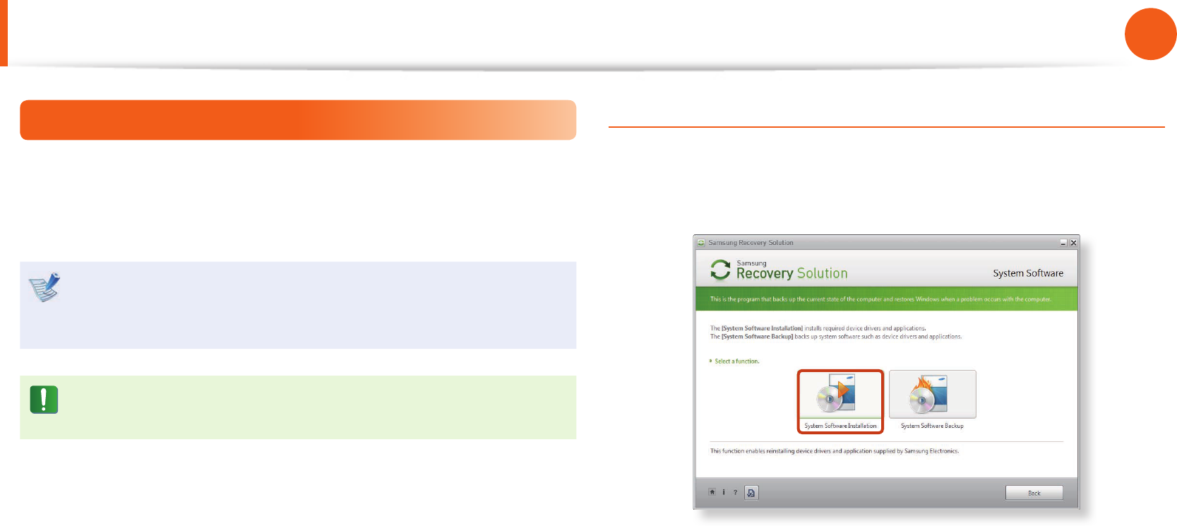
1 When the initial menu screen appears, click System Software
> System Software Installation.
2 Move to the Easy Software Manager.
Using the Easy Software Manager, you can install device
drivers and applications.
3 After the installation is complete, the computer will restart.
Samsung Recovery Solution (Optional)
92
93
Chapter 4.
Backup / Restore
Samsung Recovery Solution (Optional)
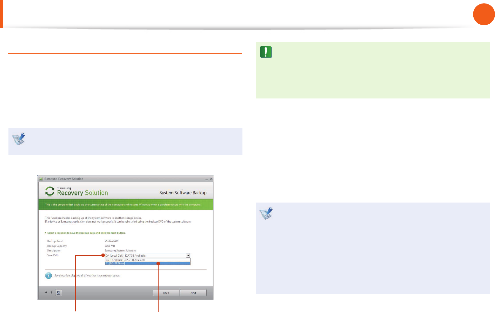
System Software Backup
1 When the initial menu screen appears, click System Software
> System Software Backup.
2 Specify the Save Path.
If your computer has a DVD-Writer, you can specify the DVD
drive as the Save Path.
Select Drive D. Select the DVD drive.
If you have speci ed a hard disk drive or a removable disk as
the Save Path, the SamsungSoftware folder is created on
the corresponding drive (e.g. D:\) and the system software
programs are saved to that folder. Take care to not delete the
folder.
3 If you click the Next button, the Software Backup begins. If
you have selected the DVD drive as the Save Path, the “Insert
a blank DVD” message appears. Insert a blank DVD and click
the OK button.
4 After the backup, the System Software Backup is
completed message appears.
If you want to install the System Software Programs backed •
up on the drive, run the SecSWMgrGuide.exe le in the
SystemSoftware folder.
When installing System Software Programs from the •
backed-up DVD, insert the DVD and follow the System
Software Installation directions.
To delete Samsung Recovery Solution, refer to the Help •
section of the program.

94
Chapter 4.
Backup / Restore
Recovery Solution Representation (Optional)
What is a Recovery Area?
Samsung computers have an additional partition to recover •
computers or save backup les.
(Only for models with the Samsung Recovery Solution.)
This partition is called a Recovery Area and it includes a recovery
image that comprises of the OS and application programs.
You can either double-click the Samsung Recovery Solution icon •
on the desktop or press F4 while booting the computer to enter
the Recovery Area. Then you can back up the present computer
state or recover the computer from backed up images.
For deleting the Recovery Area, you need to use an additional •
Recovery Area Removal Tool. After deleting the recovery area,
you can use the newly created partition for other uses, such as
for saving personal data. Be careful that once the recovery area is
deleted, the Samsung Recovery Solutions will not work anymore.
The capacity representation of the hard disk drive(HDD)
in Windows is dierent from the product specications.
The capacity of the storage device (HDD) of the manufacturer is •
calculated assuming that 1KB=1,000 Bytes. However, the operating
system (Windows) calculates the storage device capacity assuming
that 1KB=1,024 Bytes, and therefore the capacity representation of
the HDD in Windows is smaller than the actual capacity.
This is due to the dierence in capacity calculation and does
not mean the installed HDD is dierent from the product
specications.
The capacity representation in Windows may be smaller than the •
actual capacity because some programs occupy a certain area of
the HDD outside of Windows.
For models with Samsung Recovery Solution, the HDD capacity •
representation in Windows may be smaller than the actual
capacity because Samsung Recovery Solution uses a hidden area
of about 5~20GB of the HDD to save the recovery image, and
that hidden area is not counted towards the total size available to
Windows.
The size of Samsung Recovery Solution varies by models because
of the dierent size of applied programs.
Samsung Recovery Solution (Optional)

Chapter 5.
Appendix
Important Safety Information 96
Replacement Parts and Accessories 98
Regulatory Compliance Statements 100
WEEE Symbol Information 115
Product Speci cations 116
Glossary 118
Index 122

96
Chapter 5
Appendix
Safety Instructions
Your system is designed and tested to meet the latest standards
for safety of information technology equipment. However, to
ensure safe use of this product, it is important that the safety
instructions marked on the product and in the documentation are
followed.
Always follow these instructions to help guard against
personal injury and damage to your system.
Setting Up your System
Read and follow all instructions marked on the product and in •
the documentation before you operate your system. Retain all
safety and operating instructions for future use.
Do not use this product near water or a heat source such as a •
radiator.
Set up the system on a stable work surface.•
The product should be operated only with the type of power •
source indicated on the rating label.
Ensure that the electrical outlet you are using to power your •
equipment is easily accessible in case of re or short circuit.
If your computer has a voltage selector switch, make sure that •
the switch is in the proper position for your area.
Openings in the computer case are provided for ventilation. •
Do not block or cover these openings. Make sure you provide
adequate space, at least 6 inches (15 cm), around the system
for ventilation when you set up your work area. Never insert
objects of any kind into the computer ventilation openings.
Ensure that the fan vents on the bottom of the casing are clear •
at all times. Do not place the computer on a soft surface, doing
so will block the bottom vents.
If you use an extension cord with this system, make sure that the •
total power rating on the products plugged into the extension
cord does not exceed the extension cord power rating.
For Notebooks with glossy display bezels the user should •
consider the placement of the Notebook as the bezel may
cause disturbing reections from surrounding light and bright
surfaces.
Important Safety Information

96
97
Chapter 5
Appendix
Care During Use
Do not walk on the power cord or allow anything to rest on it.•
Do not spill anything on the system. The best way to avoid •
spills is to not eat or drink near your system.
Some products have a replaceable CMOS battery on the •
system board. There is a danger of explosion if the CMOS
battery is replaced incorrectly. Replace the battery with the
same or equivalent type recommended by the manufacturer.
Dispose of batteries according to the manufacturers
instructions. If the CMOS battery requires replacement insure
that a qualied technician performs the task.
When the computer is turned o, a small amount of electrical •
current still ows through the computer.
To avoid electrical shock, always unplug all power cables,
remove the battery and modem cables from the wall outlets
before cleaning the system.
Unplug the system from the wall outlet and refer servicing to •
qualied personnel if:
– The power cord or plug is damaged.
– Liquid has been spilled into the system.
– The system does not operate properly when the operating
instructions are followed.
– The system was dropped or the casing is damaged.
– The system performance changes.
The Instruction On Safety Operation of NotePC
1.When installing and operating devices please refer to safety
requirements in the user guide.
2.Devices can be used only with the equipment specied in the
technical specications of the devices.
3. If any smell of burning or smoke is detected from the computer
the unit should be switched o and battery removed. The unit
should be checked by a qualied technician before reuse.
4.Service and repair of devices should be carried out by
authorized service centers.
5.Do not allow your portable computer to operate with the base
resting directly on exposed skin for extended periods of time.
The surface temperature of the base will rise during normal
operation (particularly when AC Power is present). Allowing
sustained contact with exposed skin can cause discomfort or
eventually a burn.
Important Safety Information

98
Chapter 5
Appendix
Replacement Parts and Accessories
Use only replacement parts and accessories recommended by
manufacturer.
To reduce the risk of re, use only No. 26 AWG or larger
telecommunications line cord.
Do not use this product in areas classi ed as hazardous.
Such areas include patient care areas of medical and dental
facilities, oxygen rich environments, or industrial areas.
Battery Disposal
Do not put rechargeable batteries or products powered by
non-removable rechargeable batteries in the garbage.
Contact the Samsung Helpline for information on how to dispose
of batteries that you cannot use or recharge any longer.
Follow all local regulations when disposing of old batteries.
THERE IS A RISK OF EXPLOSION IF BATTERY IS REPLACED BY
AN INCORRECT TYPE.
DISPOSE OF USED BATTERIES ACCORDING TO THE
INSTRUCTIONS.
Laser Safety
All systems equipped with CD or DVD drives comply with the
appropriate safety standards, including IEC 60825-1. The laser
devices in these components are classi ed as “Class 1 Laser
Products” under a US Department of Health and Human Services
(DHHS) Radiation Performance Standard. Should the unit ever
need servicing, contact an authorized service location.
Laser Safety Note:•
Use of controls or adjustments or performance of
procedures other than those speci ed in this manual
may result in hazardous radiation exposure. To prevent
exposure to laser beams, do not try to open the enclosure
of a CD or DVD drive.
Class 1M laser radiation when operating part is open.•
Do not view directly with optical instruments.
Class 3B invisible laser radiation when open.•
Avoid exposure to the beam.

98
99
Chapter 5
Appendix
Replacement Parts and Accessories
Connect and Disconnect the AC adapter
The socket-outlet shall be installed near the equipment and shall
be easily accessible.
Do not unplug the power cord by pulling the cable only.
Power Cord Requirements
The power cord set (wall plug, cable and AC adapter plug) you
received with your computer meets the requirements for use in
the country where you purchased your equipment.
Power cord sets for use in other countries must meet the
requirements of the country where you use the computer. For
more information on power cord set requirements, contact your
authorized dealer, reseller, or service provider.
General Requirements
The requirements listed below are applicable to all countries:
All power cord sets must be approved by an acceptable •
accredited agency responsible for evaluation in the country
where the power cord set will be used.
The power cord set must have a minimum current capacity •
of 7 A and a nominal voltage rating of 125 or 250 volts AC, as
required by each country’s power system. (USA ONLY)
The appliance coupler must meet the mechanical conguration •
of an EN 60 320/IEC 320 Standard Sheet C7 (or C5) connector,
for mating with appliance inlet on the computer.

100
Chapter 5
Appendix
Regulatory Compliance Statements
Wireless Guidance
(If tted with 2.4G band or 5G band)
Low power, Radio LAN type devices (radio frequency (RF) wireless
communication devices), operating in the 2.4GHz/5GHz Band, may
be present (embedded) in your notebook system. The following
section is a general overview of considerations while operating a
wireless device.
Additional limitations, cautions, and concerns for specic countries
are listed in the specic country sections (or country group
sections). The wireless devices in your system are only qualied for
use in the countries identied by the Radio Approval Marks on the
system rating label. If the country you will be using the wireless
device in, is not listed, please contact your local Radio Approval
agency for requirements. Wireless devices are closely regulated
and use may not be allowed.
The RF eld strength of the wireless device or devices that may
be embedded in your notebook are well below all international
RF exposure limits as known at this time. Because the wireless
devices (which may be embedded into your notebook) emit less
energy than is allowed in radio frequency safety standards and
recommendations, manufacturer believes these devices are safe
for use. Regardless of the power levels, care should be taken to
minimize human contact during normal operation.
Some circumstances require restrictions on wireless devices.
Examples of common restrictions are listed on the next page:
Radio frequency wireless communication can interfere •
with equipment on commercial aircraft. Current aviation
regulations require wireless devices to be turned o while
traveling in an airplane.
802.11ABGN (also known as wireless Ethernet or Wi) and
Bluetooth communication devices are examples of devices
that provide wireless communication.
In environments where the risk of interference to other •
devices or services is harmful or perceived as harmful,
the option to use a wireless device may be restricted or
eliminated. Airports, Hospitals, and Oxygen or ammable
gas laden atmospheres are limited examples where use
of wireless devices may be restricted or eliminated. When
in environments where you are uncertain of the sanction
to use wireless devices, ask the applicable authority for
authorization prior to use or turning on the wireless device.
Every country has dierent restrictions on the use of •
wireless devices. Since your system is equipped with
a wireless device, when traveling between countries
with your system, check with the local Radio Approval
authorities prior to any move or trip for any restrictions on
the use of a wireless device in the destination country.
If your system came equipped with an internal embedded •
wireless device, do not operate the wireless device unless
all covers and shields are in place and the system is fully
assembled.

100
101
Chapter 5
Appendix
Regulatory Compliance Statements
Wireless devices are not user serviceable. Do not modify •
them in any way. Modication to a wireless device will void
the authorization to use it. Please contact manufacturer for
service.
Only use drivers approved for the country in which •
the device will be used. See the manufacturer System
Restoration Kit, or contact manufacturer Technical Support
for additional information.
United States of America
USA and Canada Safety Requirements and Notices
Do not touch or move antenna while the unit is transmitting or
receiving.
Do not hold any component containing the radio such that the
antenna is very close or touching any exposed parts of the body,
especially the face or eyes, while transmitting.
Do not operate the radio or attempt to transmit data unless the
antenna is connected; if not, the radio may be damaged.
Use in specic environments:
The use of wireless devices in hazardous locations is limited by the
constraints posed by the safety directors of such environments.
The use of wireless devices on airplanes is governed by the Federal
Aviation Administration (FAA).
The use of wireless devices in hospitals is restricted to the limits
set forth by each hospital.
Explosive Device Proximity Warning
Do not operate a portable transmitter (such as a wireless
network device) near unshielded blasting caps or in an
explosive environment unless the device has been modied
to be qualied for such use.

102
Chapter 5
Appendix
Use On Aircraft Caution
Regulations of the FCC and FAA prohibit airborne operation
of radio-frequency wireless devices because their signals
could interfere with critical aircraft instruments.
Other Wireless Devices
Safety Notices for Other Devices in the Wireless Network:
Refer to the documentation supplied with wireless Ethernet
adapters or other devices in the wireless network.
The Part 15 radio device operates on a non-interference basis
with other devices operating at this frequency. Any changes
or modication to said product not expressly approved by
Intel could void the user’s authority to operate this device.
Unintentional Emitter per FCC Part 15
This device complies with Part 15 of the FCC Rules. Operation is
subject to the following two conditions:(1) this device may not
cause harmful interference, and (2) this device must accept any
interference received, including interference that may cause
undesired operation.
This equipment has been tested and found to comply
with the limits for a Class B digital device pursuant to Part
15 of the FCC Rules. These limits are designed to provide
reasonable protection against harmful interference in a
residential installation. This equipment generates, uses,
and can radiate radio frequency energy. If not installed
and used in accordance with the instructions, it may cause
harmful interference. If this equipment does cause harmful
interference to radio or television reception, which can be
determined by turning the equipment o and on, the user is
encouraged to try to correct the interference by one or more
of the following measures:
Reorient or relocate the receiving antenna.•
Increase the separation between the equipment and •
receiver.
Connect the equipment into an outlet on a circuit dierent •
from that to which the receiver is connected.
Consult the dealer or an experienced radio/TV technician •
for help.
Regulatory Compliance Statements

102
103
Chapter 5
Appendix
If necessary, the user should consult the dealer or an experienced
radio/television technician for additional suggestions. The user
may nd the following booklet helpful: “Something About
Interference.”
This is available at FCC local regional oces. Our company is not
responsible for any radio or television interference caused by
unauthorized modications of this equipment or the substitution
or attachment of connecting cables and equipment other than
those specied by our company. The correction will be the
responsibility of the user. Use only shielded data cables with this
system.
Intentional emitter per FCC Part 15
(If tted with 2.4G band or 5G band)
Low power, Radio LAN type devices (radio frequency (RF) wireless
communication devices), operating in the 2.4GHz/5GHz Band, may
be present (embedded) in your notebook system. This section is
only applicable if these devices are present. Refer to the system
label to verify the presence of wireless devices.
Wireless devices that may be in your system are only qualied for
use in the United States of America if an FCC ID number is on the
system label.
This device is restricted to indoor use due to its operation in the
5.15 to 5.25 GHz frequency range. FCC requires this product to be
used indoors for the frequency range 5.15 to 5.25 GHz to reduce
the potential for harmful interference to co-channel Mobile
Satellite systems. High power radars are allocated as primary users
of the 5.25 to 5.35 GHz and 5.65 to 5.85 GHz bands. These radar
stations can cause interference with and /or damage this device.
Operation of this device is subject to the following two conditions:
(1) This device may not cause harmful interference, and (2)
this device must accept any interference received, including
interference that may cause undesired operation of the device.
Wireless devices are not user serviceable. Do not modify
them in any way.
Modication to a wireless device will void the authorization
to use it. Contact manufacturer for service.
Regulatory Compliance Statements

104
Chapter 5
Appendix
FCC Part 68 (If tted with a modem device.)
This equipment compiles with part of the FCC rules. On the
back of this equipment is a label that contains, among other
information, the FCC registration number and ringer equivalence
number (REN) for this equipment. If requested, this information
must be provided to the telephone company.
This equipment uses the following USOC jacks : RJ11C
An FCC compliant telephone cord and modular plug is provided
with this equipment. This equipment is designed to be connected
to the telephone network or promises wiring using a compatible
modular jack which is Part 68 compliant. See Installation
Instructions for details.
The REN is used to determine the quantity of devices which may
be connected to telephone line. Excessive RENs on the telephone
line may result in the devices not ringing in response to an
incoming call. In most, but not all areas, the sum of RENs should
not exceed ve (5.0). To be certain of the number of devices that
may be connected to a line, as determined by total RENs, contact
the local telephone company to determine the maximum REN for
the calling area.
If the terminal equipment causes harm to the telephone network,
the Telephone Company will notify you in advance that temporary
discontinuance of service may be required. But if advance notice
is not practical, the telephone company will notify the customer
as soon as possible. Also, you will be advised of your right to le a
complaint with the FCC if you believe it is necessary.
The telephone company may make changes in its facilities,
equipment, operations, or procedures that could aect the
operation of the equipment. If this happens, the telephone
company will provide advanced notice in order for you to make
necessary modications to maintain uninterrupted service.
If trouble is experienced with this equipment (Modem) for repair
or warranty information, please contact your local distributor.
If the equipment is causing harm to the telephone network,
the telephone company may request that you disconnect the
equipment until the problem is resolved.
The user must use the accessories and cables supplied by the
manufacturer to get optimum performance from the product.
No repairs may be done by the customer.
This equipment cannot be used on public coin phone service
provided by the telephone company. Connection to party line
service is subject to state taris.
The Telephone Consumer Protection Act of 1991 makes it
unlawful for any person to use a computer or other electronic
device, including fax machines, to send any message unless such
message clearly contains in a margin at the top or bottom of
each transmitted page or on the rst page of the transmission,
the date and time it is sent and an identication of the business
or other entity, or other individual sending the message and the
telephone number of the sending machine or such business, other
entity, or individual. (The telephone number provided may not
be any number for which charges exceed local or long-distance
transmission charges.)
In order to program this information into your fax machine, refer
to your communications software user manual.
Regulatory Compliance Statements

104
105
Chapter 5
Appendix
Canada
Unintentional Emitter per ICES-003
This digital apparatus does not exceed the Class B limits for radio
noise emissions from digital apparatus as set out in the radio
interference regulations of Industry Canada.
Le présent appareil numérique n’émet pas de bruits
radioélectriques dépassant les limitesapplicables aux appareils
numériques de Classe B prescrites dans le règlement sur le
brouillage radioélectrique édicté par Industrie Canada.
Intentional Emitter per RSS 210
This device complies with RSS 210 of Industry Canada. Operation
is subject to the following two conditions: (1) this device may not
cause interference, and (2) this device must accept any interference,
including interference that may cause undesired operation of this
device.”
L‘ utilisation de ce dispositif est autorisée seulement aux
conditions suivantes : (1) il ne doit pas produire de brouillage et (2)
l’ utilisateur du dispositif doit étre prêt à accepter tout brouillage
radioélectrique reçu, même si ce brouillage est susceptible de
compromettre le fonctionnement du dispositif.
The term “IC” before the equipment certication number only
signies that the Industry Canada technical specications were
met. To reduce potential radio interference to other users, the
antenna type and its gain should be so chosen that the equivalent
isotropically radiated power (EIRP) is not more than that required
for successful communication. To prevent radio interference
to the licensed service, this device is intended to be operated
indoors and away from windows to provide maximum shielding.
Equipment (or its transmit antenna) that is installed outdoors is
subject to licensing.
Pour empecher que cet appareil cause du brouillage au service
faisant l’objet d’une licence, il doit etre utilize a l’interieur et devrait
etre place loin des fenetres an de Fournier un ecram de blindage
maximal. Si le matriel (ou son antenne d’emission) est installe a
l’exterieur, il doit faire l’objet d’une licence.
(If tted with 2.4G band or 5G band)
Low power, Radio LAN type devices (radio frequency (RF) wireless
communication devices), operating in the 2.4GHz/5GHz Band, may
be present (embedded) in your notebook system. This section is
only applicable if these devices are present. Refer to the system
label to verify the presence of wireless devices.
Wireless devices that may be in your system are only qualied for
use in Canada if an Industry Canada ID number is on the system
label.
Regulatory Compliance Statements

106
Chapter 5
Appendix
When using IEEE 802.11a wireless LAN, this product is restricted to
indoor use due to its operation in the 5.15- to 5.25-GHz frequency
range. Industry Canada requires this product to be used indoors
for the frequency range of 5.15 GHz to 5.25 GHz to reduce the
potential for harmful interference to co-channel mobile satellite
systems. High power radar is allocated as the primary user of the
5.25- to 5.35-GHz and 5.65 to 5.85-GHz bands. These radar stations
can cause interference with and/or damage to this device.
The maximum allowed antenna gain for use with this device
is 6dBi in order to comply with the E.I.R.P limit for the 5.25- to
5.35 and 5.725 to 5.85 GHz frequency range in point-to-point
operation.
The power output of the wireless device (or devices), which may
be embedded in your notebook, is well below the RF exposure
limits as set by Industry Canada.
Operation of this device is subject to the following two conditions:
(1) This device may not cause harmful interference, and (2)
this device must accept any interference received, including
interference that may cause undesired operation of the device.
To prevent radio interference to licensed service, this device
is intended to be operated indoors and away from windows
to provide maximum shielding. Equipment (or its transmit
antenna) that is installed outdoors is subject to licensing.
Wireless devices are not user serviceable. Do not modify
them in any way. Modication to a wireless device will void
the authorization to use it. Contact manufacturer for service.
(Si l’appareil est équipé d’une bande 2,4 G ou 5 G)
Des dispositifs de basse puissance, de type radio LAN
(périphériques de communication sans l par radiofréquence
RF) fonctionnant sur une bande de 2.4GHz/5GHz sont peut-
être intégrés dans votre appareil. Cette section est applicable
uniquement si ces dispositifs sont présents. Consultez l’étiquette
du système pour vériez la présence de dispositifs sans l.
Les dispositifs sans l qui peuvent être intégrés dans votre système
sont uniquement aptes pour une utilisation au Canada si l’étiquette
du système présente un nombre d’identication d’Industrie
Canada.
En cas d’utilisation d’un LAN sans l IEEE 802.11a, ce produit ne
peut être utilisé qu’à l’intérieur en raison de son fonctionnement
dans une plage des fréquences allant de 5,15 à 5,25 GHz. Industrie
Canada exige l’utilisation de ce produit à l’intérieur pour une
plage des fréquences allant de 5,15 à 5,25 GHz an de réduire
les éventuelles interférences nuisibles avec les systèmes mobiles
par satellite du même canal. Le radar de grande puissance est
considéré comme l’utilisateur principal des bandes de 5,25 à 5,35
GHz et de 5,65 à 5,85 GHz. Ces stations radar peuvent provoquer
des interférences avec ce périphérique et/ou l’endommager.
Le gain d’antenne maximum autorisé avec ce périphérique est
de 6 dBi an de respecter la limite de P.I.R.E. pour une plage des
fréquences de 5,25 à 5,35 GHz et de 5,725 à 5,85 GHz dans un
fonctionnement point à point.
La sortie de puissance du dispositif sans l (ou des dispositifs) qui
peut être intégré dans votre système est bien inférieure aux limites
d’exposition de RF établies par Industrie Canada.
Regulatory Compliance Statements

106
107
Chapter 5
Appendix
Son utilisation est soumise aux deux conditions suivantes : 1) ce
dispositif ne peut pas provoquer d’interférences nuisibles et 2
2) ce dispositif doit accepter toute interférence reçue, y compris
les interférences qui peuvent provoquer des anomalies dans le
système.
An de prévenir des interférences de radio au service
autorisé, ce dispositif est prévu pour être utilisé à l’intérieur et
éloigné des fenêtres pour fournir une protection maximum.
Un équipement (ou son antenne de transmission) qui est
installé à l’extérieur est sujet à une autorisation.
Les dispositifs sans l ne peuvent pas être réparés par
l’utilisateur. Ne les modiez en aucune façon. La modication
d’un dispositif sans l annulera votre autorisation à son
utilisation. Contactez le fabricant pour la réparation.
Telecommunications per DOC notice
(for products tted with an IC-compliant modem)
The Industry Canada label identies certied equipment.
This certication means that the equipment meets certain
telecommunications network protective, operation, and safety
requirements. The Department does not guarantee the equipment
will operate to the users’ satisfaction.
Before installing this equipment, users should make sure that
it is permissible to be connected to the facilities of the local
telecommunications company. The equipment must also be
installed using an acceptable method of connection. In some
cases, the inside wiring associated with a single-line individual
service may be extended by means of a certied connector
assembly. The customer should be aware that compliance with
the above conditions may not prevent degradation of service in
some situations.
Repairs to certied equipment should be made by an authorized
Canadian maintenance facility designated by the supplier. Any
repairs or alterations made by the user to this equipment, or
equipment malfunctions, may give the telecommunications
company cause to request the user to disconnect the equipment.
Users should make sure, for their own protection, that the
electrical ground connections of the power utility, telephone lines,
and internal metallic water pipe system, if present, are connected
together. This precaution may be particularly important in rural
areas.
Regulatory Compliance Statements

108
Chapter 5
Appendix
To avoid electrical shock or equipment malfunction do not
attempt to make electrical ground connections by yourself.
Contact the appropriate inspection authority or an electrician,
as appropriate.
The Ringer Equivalence Number (REN) assigned to each
terminal device provides an indication of the maximum number
of terminals allowed to be connected to a telephone interface.
The termination on an interface may consist of any combination of
devices subject only to the requirement that the sum of the Ringer
Equivalence Numbers of all the devices does not exceed 5.
Déclarations sur les télécommunications selon DOC
(pour des produits munis d’un modem homologué par
la IC)
L’étiquette d’Industrie Canada identie un équipement autorisé.
Cette autorisation signie que l’équipement satisfait certaines
exigences pour la sécurité, fonctionnement et protection des
réseaux téléphoniques. Le département ne garantie pas que
l’équipement fonctionne comme le désirerait l’utilisateur.
Avant d’installer l’équipement, les utilisateurs doivent s’assurer
que leur connexion aux installations de la compagnie de
télécommunication locale soit permise.
L’équipement doit être également installé selon une méthode
acceptable de connexion. Dans certains cas, l’installation
électrique associée à un service de ligne individuel peut être
rallongé par un connecteur homologué. Le client doit savoir que
la conformité aux conditions précédentes ne garantit pas un
fonctionnement parfait dans toutes les situations.
Les réparations de l’équipement homologué doivent être
eectuées dans les installations de maintenance canadiennes
autorisées par le fournisseur. Les réparations ou modications
eectuées par l’utilisateur sur cet équipement, ou anomalies
de l’équipement, peuvent faire que la compagnie de
télécommunication demande la déconnexion de l’équipement.
Les utilisateurs doivent s’assurer, pour leur propre protection, que
les raccordements électriques à la terre, les lignes de téléphone
et l’infrastructure de la conduite d’eau, si il y en a, sont connectés
ensemble. Cette précaution peut être particulièrement importante
dans les zones rurales.
An d’éviter une électrocution ou le disfonctionnement
de l’équipement, n’essayez pas de faire vous-même les
raccordements électriques à la terre. Contactez l’autorité
inspectrice adéquate ou un électricien, selon il conviendra.
Le Numéro d’équivalence d’appel (REN) attribué à chaque
dispositif terminal fourni une indication du nombre maximum
de terminales qui peuvent être connectées à une interface
téléphonique. Le bout d’une interface peut contenir n’importe
quelle combinaison de dispositifs sujets uniquement à la
condition que le total des numéros d’équivalence d’appel de tous
les dispositifs ne dépasse pas 5.
Regulatory Compliance Statements

108
109
Chapter 5
Appendix
Brazil
Este equipamento opera em caráter secundário, isto é, não
tem direito a proteção contra interferência prejudicial, mesmo
de estações do mesmo tipo, e não pode causar interferência a
sistemas operando em caráter primário.
European Union
European Union CE Marking and Compliance Notices
Products intended for sale within the European Union are marked
with the Conformité Européene (CE) Marking, which indicates
compliance with the applicable Directives and European standards
and amendments identied below. This equipment also carries
the Class 2 identier.
The following information is only applicable to systems labeled
with the CE mark .
European Directives
This Information Technology Equipment has been tested and
found to comply with the following European directives:
EMC Directive 2004/108/EC•
Low Voltage Directive 2006/95/EC•
R&TTE Directive 1999/5/EC•
Manufacturer Information
Samsung Electronics Co., Ltd.
416, Maetan-3Dong, Yeongtong-Gu, Suwon-City, Gyeonggi-Do,
443-742, Korea
Samsung Electronics Suzhou Computer Co., Ltd.
No. 198, Fangzhou Road, Suzhou Industrial Park, Jiangsu Province,
215021, China
Tel: +86-512-6253-8988
For the web or the phone number of Samsung Service Centre, see
the Warranty or contact the retailer where you purchased your
product.
Regulatory Compliance Statements
110
Chapter 5
Appendix
European Radio Approval Information
(for products tted with EU-approved radio devices)
This Product is a Notebook computer; low power, Radio LAN type
devices (radio frequency (RF) wireless communication devices),
operating in the 2.4GHz/5GHz band, may be present (embedded)
in your notebook system which is intended for home or o ce use.
This section is only applicable if these devices are present. Refer to
the system label to verify the presence of wireless devices.
Wireless devices that may be in your system are only quali ed for
use in the European Union or associated areas if a CE mark
with a Noti ed Body Registration Number and the Alert Symbol is
on the system label.
The power output of the wireless device or devices that may be
embedded in you notebook is well below the RF exposure limits
as set by the European Commission through the R&TTE directive.
The low band 5.15 - 5.35 GHz is for indoor use only.
See 802.11b and 802.11g restrictions for speci c countries
or regions within countries under the heading “European
Economic Area Restrictions” below.
EU R&TTE Compliance Statements
Česky
[Czech]
Samsung tímto prohlašuje, že tento Notebook
PC je ve shodě se základními požadavky a
dalšími příslušnými ustanoveními směrnice
1999/5/ES.
Dansk
[Danish]
Undertegnede Samsung erklærer herved, at
følgende udstyr Notebook PC overholder de
væsentlige krav og øvrige relevante krav i
direktiv 1999/5/EF.
Deutsch
[German]
Hiermit erklärt Samsung, dass sich das Gerät
Notebook PC in Übereinstimmung mit den
grundlegenden Anforderungen und den
übrigen einschlägigen Bestimmungen der
Richtlinie 1999/5/EG be ndet.
Eesti
[Estonian]
Käesolevaga kinnitab Samsung seadme
Notebook PC vastavust direktiivi 1999/5/
EÜ põhinõuetele ja nimetatud direktiivist
tulenevatele teistele asjakohastele sätetele.
English
Hereby, Samsung, declares that this Notebook
PC is in compliance with the essential
requirements and other relevant provisions of
Directive 1999/5/EC.
Español
[Spanish]
Por medio de la presente Samsung declara
que el Notebook PC cumple con los requisitos
esenciales y cualesquiera otras disposiciones
aplicables o exigibles de la Directiva 1999/5/CE.
Regulatory Compliance Statements
110
111
Chapter 5
Appendix
Ελληνική
[Greek]
ΜΕ ΤΗΝ ΠΑΡΟΥΣΑ Samsung ΔΗΛΩΝΕΙ ΟΤΙ
Notebook PC ΣΥΜΜΟΡΦΩΝΕΤΑΙ ΠΡΟΣ ΤΙΣ
ΟΥΣΙΩΔΕΙΣ ΑΠΑΙΤΗΣΕΙΣ ΚΑΙ ΤΙΣ ΛΟΙΠΕΣ
ΣΧΕΤΙΚΕΣ ΔΙΑΤΑΞΕΙΣ ΤΗΣ ΟΔΗΓΙΑΣ 1999/5/ΕΚ.
Français
[French]
Par la présente Samsung déclare que l’appareil
Notebook PC est conforme aux exigences
essentielles et aux autres dispositions
pertinentes de la directive 1999/5/CE.
Italiano
[Italian]
Con la presente Samsung dichiara che questo
Notebook PC è conforme ai requisiti essenziali
ed alle altre disposizioni pertinenti stabilite
dalla direttiva 1999/5/CE.
Latviski
[Latvian]
Ar šo Samsung deklarē, ka Notebook PC atbilst
Direktīvas 1999/5/EK būtiskajām prasībām un
citiem ar to saistītajiem noteikumiem.
Lietuvių
[Lithuanian]
Šiuo Samsung deklaruoja, kad šis Notebook PC
atitinka esminius reikalavimus ir kitas 1999/5/
EB Direktyvos nuostatas.
Nederlands
[Dutch]
Hierbij verklaart Samsung dat het toestel
Notebook PC in overeenstemming is met
de essentiële eisen en de andere relevante
bepalingen van richtlijn 1999/5/EG.
Malti
[Maltese]
Hawnhekk, Samsung, jiddikjara li dan
Notebook PC jikkonforma mal-ħtiāijiet
essenzjali u ma provvedimenti oħrajn relevanti
li hemm d-Dirrettiva 1999/5/EC.
Magyar
[Hungarian]
Alulírott, Samsung nyilatkozom, hogy a
Notebook PC megfelel a vonatkozó alapvetõ
követelményeknek és az 1999/5/EC irányelv
egyéb elõírásainak.
Polski
[Polish]
Niniejszym Samsung oświadcza, Ŝe Notebook
PC jest zgodny z zasadniczymi wymogami oraz
pozostałymi stosownymi postanowieniami
Dyrektywy 1999/5/EC.
Português
[Portuguese]
Samsung declara que este Notebook PC está
conforme com os requisitos essenciais e outras
disposições da Directiva 1999/5/CE.
Slovensko
[Slovenian]
Samsung izjavlja, da je ta Notebook PC v skladu
z bistvenimi zahtevami in ostalimi relevantnimi
določili direktive 1999/5/ES.
Slovensky
[Slovak]
Samsung týmto vyhlasuje, že Notebook PC
spĺňa základné požiadavky a všetky príslušné
ustanovenia Smernice 1999/5/ES.
Suomi
[Finnish]
Samsung vakuuttaa täten että Notebook
PC tyyppinen laite on direktiivin 1999/5/
EY oleellisten vaatimusten ja sitä koskevien
direktiivin muiden ehtojen mukainen.
Svenska
[Swedish]
Härmed intygar Samsung att denna Notebook
PC står I överensstämmelse med de väsentliga
egenskapskrav och övriga relevanta
bestämmelser som framgår av direktiv 1999/5/
EG.
Regulatory Compliance Statements

112
Chapter 5
Appendix
Íslenska
[Icelandic]
Hér með lýsir Samsung y r því að Notebook PC
er í samræmi við grunnkröfur og aðrar kröfur,
sem gerðar eru í tilskipun 1999/5/EC.
Norsk
[Norwegian]
Samsung erklærer herved at utstyret Notebook
PC er i samsvar med de grunnleggende krav og
øvrige relevante krav i direktiv 1999/5/EF.
Türkiye
[Türkçe]
Bu belge ile, Samsung bu Notebook PC’nin
1999/5/EC Yönetmeliğinin temel gerekliliklerine
ve ilgili hükümlerine uygun olduğunu beyan
eder.
To view the EU Declaration of Conformity for this product (in
English only), go to: http://www.samsung.com/uk/support/
download/supportDownMain.do then search the model number
of the product.
If the Declaration of Conformity for the model you are interested
in is not available on our web-site, please contact your distributor.
European Economic Area Restrictions
Local Restriction of 802.11b/802.11g Radio Usage
[Note to integrator: The following statements on local restrictions
must be published in all end-user documentation provided with
the system or product incorporating the wireless product.]
Due to the fact that the frequencies used by 802.11b/802.11g
wireless LAN devices may not yet be harmonized in all
countries, 802.11b/802.11g products are designed for use
only in speci c countries or regions, and are not allowed
to be operated in countries or regions other than those of
designated use.
As a user of these products, you are responsible for ensuring
that the products are used only in the countries or regions
for which they were intended and for verifying that they
are con gured with the correct selection of frequency and
channel for the country or region of use. Any deviation from
permissible settings and restrictions in the country or region
of use could be an infringement of local law and may be
punished as such.
Regulatory Compliance Statements

112
113
Chapter 5
Appendix
The European variant is intended for use throughout the European
Economic Area. However, authorization for use is further restricted
in particular countries or regions within countries, as follows:
General
European standards dictate maximum radiated transmit power
of 100 mW eective isotropic radiated power (EIRP) and the
frequency range 2400 – 2483.5 MHz.
The low band 5.15 - 5.35 GHz is for indoor use only.
Belgium
The product may be used outdoors, but for outdoor transmissions
over a distance of 300m or more, a license from the BIPT is
required.
This restriction should be indicated in the manual as follows:
Dans le cas d’une utilisation privée, à l’extérieur d’un bâtiment, au-
dessus d’un espace public, aucun enregistrement n’est nécessaire
pour une distance de moins de 300m. Pour une distance
supérieure à 300m un enregistrement auprès de l’IBPT est requise.
Pour une utilisation publique à l’extérieur de bâtiments, une
licence de l’IBPT est requise. Pour les enregistrements et licences,
veuillez contacter l’IBPT.
France
For Metropolitan departments:
2.400 - 2.4835 GHz for indoor use.
2.400 - 2.454 GHz (channels 1 to 7) for outdoor use.
For Guadeloupe, Martinique, St Pierre et Miquelon, Mayotte:
2.400 - 2.4835 GHz for indoor and outdoor use.
For Reunion, Guyane:
2.400 - 2.4835 GHz for indoor use.
2.420 - 2.4835 GHz for outdoor use (channels 5 to 13)
The low band 5.15 - 5.35 GHz is for indoor use only.
Regulatory Compliance Statements

114
Chapter 5
Appendix
European Telecommunication Information
(for products tted with EU-approved modems)
Marking by the symbol indicates compliance of this equipment
to the Radio and Telecom Terminal Equipment Directive 1999/5/
EC. Such marking is indicative that this equipment meets or
exceeds the following technical standards:
CTR 21 - Attachment requirements for pan-European approval for
connection to the analogue Public Switched Telephone Networks
(PSTNs) of TE (excluding TE supporting voice telephony services) in
which network addressing, if provided, is by means of Dual Tone
Multi-Frequency (DTMF) signaling.
Although this equipment can use either loop disconnect
(pulse) or DTMF (tone) signaling, only the performance of
the DTMF signaling is subject to regulatory requirements for
correct operation.
It is therefore strongly recommended that the equipment
is set to use DTMF signaling for access to public or private
emergency services. DTMF signaling also provides faster call
setup.
This equipment has been approved to Council Decision 98/482/
EEC - “CTR 21” for Pan-European single terminal connection to the
Public Switched Telephone Network (PSTN).
However, due to dierences between the individual PSTNs
provided in dierent countries, the approval does not, of itself,
give an unconditional assurance of successful operation on every
PSTN termination point. In the event of problems, you should
contact manufacturer Technical Support.
Regulatory Compliance Statements

114
115
Chapter 5
Appendix
WEEE Symbol Information
Correct disposal of this product
(Waste Electrical & Electronic Equipment)
(Applicable in the European Union and other European
countries with separate collection systems)
This marking on the product, accessories or literature indicates that
the product and its electronic accessories (e.g. charger, headset, USB
cable) should not be disposed of with other household waste at the
end of their working life.
To prevent possible harm to the environment or human health
from uncontrolled waste disposal, please separate these items from
other types of waste and recycle them responsibly to promote the
sustainable reuse of material resources.
Household users should contact either the retailer where they
purchased this product, or their local government oce, for details
of where and how they can take these items for environmentally safe
recycling.
Business users should contact their supplier and check the terms and
conditions of the purchase contract. This product and its electronic
accessories should not be mixed with other commercial wastes for
disposal.
Pb
Correct disposal of batteries in this product
(Applicable in the European Union and other European
countries with separate battery return systems.)
This marking on the battery, manual or packaging indicates that
the batteries in this product should not be disposed of with other
household waste at the end of their working life. Where marked,
the chemical symbols Hg, Cd or Pb indicate that the battery contains
mercury, cadmium or lead above the reference levels in EC Directive
2006/66. If batteries are not properly disposed of, these substances
can cause harm to human health or the environment.
To protect natural resources and to promote material re-use, please
separate batteries from other types of waste and recycle them
through your local, free battery return system.
USA ONLY
This Perchlorate warning applies only to primary CR (Maganese
Dioxide) Lithium coin cells in the product sold or distributed ONLY in
California USA.
“Perchlorate Material- special handling may apply, See www.dtsc.
ca.gov/hazardouswaste/perchlorate.”
Dispose unwanted electronics through an approved recycler.
To nd the nearest recycling location, go to our website:
www.samsung.com/recyclingdirect Or call, (877) 278-0799

116
Chapter 5
Appendix
The system specications may dier depending on the derived
models.
For detailed system specications, refer to the product catalogue.
CPU Intel i3/i5/i7 (Core) / Pentium Processor
Main Memory Memory type: DDR3 SDRAM on board
Main Chipset Intel HM65
Storage Device SSD
Graphics Intel HD Graphics (Internal)
Operating
Environment
Temperature: -5~40°C for storage,
10~32°C when operating
Humidity: 5~90% for storage,
20~80% when operating
AC/DC Rating
(Optional)
Input) 100-240VAC, 50/60Hz,
Output) 19VDC 2.1A
PC Rating (Optional) 19VDC 2.1A (40W)
Optional components may not be provided or dierent •
components may be provided depending on the computer
model.
The system specications are subject to change without •
notice.
The hard disk drive capacity of a computer in which •
Samsung Recovery Solution is installed, is represented as
smaller than the product specication.
The amount of memory that Windows can use may be •
smaller than the actual amount of memory available.
For this model, you cannot replace, add or upgrade the •
hard disk drive and the battery, memory by yourself due to
the design.
Product Specications

116
117
Chapter 5
Appendix
Product Specications
Registered Trademarks
Samsung is a registered trademark of Samsung Co., Ltd.
Intel, ATOM/Pentium/Celeron are registered trademarks of the
Intel Corporation.
Microsoft, MS-DOS, and Windows are registered trademarks of the
Microsoft Corporation.
All other product or company names mentioned herein are
registered trademarks of their respective companies.
ENERGY STAR® Partner
As an ENERGY STAR® Partner, SAMSUNG has
determined that this product meets the ENERGY STAR®
guidelines for energy eciency.

118
Chapter 5
Appendix
Glossary
The Glossary lists the terminologies used in this User Guide. For terminologies other than these, look in Windows Help.
Backup
A way to save the current data to restore it later if necessary.
A backup is a way to restore computer data when the data or
computer is damaged.
Chargeable USB
This program enables supplying power to a specic USB port when
the system is in power saving mode, hibernation mode or o.
Client
This refers to a computer that uses a shared network resource
provided by a server.
DDR SDRAM
(Double Data Rate Synchronous Dynamic Random Access Memory)
DRAM is a memory type whose cells consist of a capacitor and
transistor manufactured at a low price. SDRAM is a memory type
whose performance has been improved by synchronizing the clock
with the external CPU clock. DDR SDRAM is a memory type whose
performance has been improved by doubling the operating speed
of the SDRAM and is widely used nowadays. This computer uses
DDR SDRAM.
Device Manager
An administrative tool used to manage computer devices. You can
add or remove hardware or update a device driver using the Device
Manager.
DHCP (Dynamic Host Conguration Protocol)
This refers to automatically allocating IP addresses to the users on
the network by the network administrators.
Direct X
An application interface developed to enable Windows application
programs to access hardware devices at a very high speed. Since
the operating speed of graphics, memory and sound cards must be
very fast to provide high quality video and sound for games, Direct
X enables faster control and interaction between applications and
hardware devices. By using Direct X, the multimedia performance
of Windows has been hugely improved.
Driver
Software that interacts between the hardware and the operating
system. An operating system knows the hardware information
and controls the hardware. In general, a driver is supplied with the
corresponding hardware device.
D-sub (D-subminiature)
This is the cable connecting a general CRT monitor and the
computer. Analog video is output through this cable.

118
119
Chapter 5
Appendix
DVD (Digital Versatile Disk)
DVD was developed to replace CD (compact disk). Although the
shape and size of the disc are the same as that of a CD, the capacity
of a DVD is at least 4.7GB while the capacity of a CD is 600MB. DVD
video is digital unlike VHS (analog) video and supports MPEG2
compression and digital audio. To play a DVD, a DVD drive is
required.
eSATA
This is an external version of the SATA interface currently being
used to connect a hard disk drive or ODD in a computer. It is an
external port used to connect a main board or a hard disk drive.
Firewall
A security system used to protect an internal network or intranet
from external networks through an authentication procedure.
HDMI
This is a digital video / audio interface specication that transmits
video and audio signals over a single cable.
Hibernation Mode
A power mode that saves all data in memory to the hard disk and
turns the CPU and hard disk o. When canceling Hibernation Mode,
all application programs that were running are restored to their last
state.
Icon
This refers to a small image that represents a le that users can use.
LAN (Local Area Network)
A communications network connecting computers, printers and
other devices within a local area such as within a building. A LAN
enables all connected devices to interact with other devices on the
network. The current LAN uses the Ethernet media access control
method developed in the early 1980s. To connect to an Ethernet, a
network card called a LAN card, Ethernet card or network interface
card is required. To exchange data between computers, a protocol
is required besides the hardware equipment. Windows Vista uses
TCP/IP as the default protocol.
LCD (Liquid Crystal Display)
There are Passive Matrix and Active Matrix LCD types. This
computer uses the Active Matrix type LCD called a TFT LCD. Since
an LCD is implemented by transistors instead of a cathode-ray tube
unlike a CRT, its size can be slim. And because it does not blink, it
reduces eye strain.
MMC (MultiMedia Card) card
This is an external-type ash memory used for mobile devices such
as mobile phones or digital cameras.
Network
A group of computers and devices, such as printers and scanners,
connected by a communications link. A network can be either
small or large and can be connected permanently through cables
or temporarily through telephone lines or wireless links. The
biggest network is the Internet, a worldwide network.
Glossary

120
Chapter 5
Appendix
Network Administrator
A user who plans, congures and manages network operations.
Sometimes, a network administrator is called a system
administrator.
Notication Area
This refers to the right area of the Taskbar including program icons
such as the volume control, the power options and the time.
Partition
This refers to the act or practice of dividing the storage space of
a hard disk drive into separate data areas known as partitions. If a
100GB hard disk drive is partitioned into 2 x 50GB partitions, the
hard disk drive can be used as if there are 2 hard disk drives.
PCMCIA (Personal Computer Memory Card International
Association) card
This is an extended card slot specication for mobile computers
such as a notebook computer. Not only a memory, device but also
most peripherals such as hard disk drives, LAN cards, etc. can be
connected to this card slot.
Protocol
A protocol is a set of rules used by computers to communicate with
each other across a network. A protocol is a convention or standard
that controls or enables the connection, communication, and
data transfer between computing endpoints. It denes the data
transmission procedures and the transmission medium for more
ecient network functions.
Quick Launch
This refers to a toolbar that can be congured so that you can
launch a program such as Internet Explorer or display the Windows
Desktop with one click. You can add any icon to the quick launch
area of the Taskbar and launch frequently used program by clicking
that icon.
SD (Secure Digital) card
An SD card is a ash (non-volatile) memory card developed for
mobile devices by improving on the MMC card. Although an MMC
card can be used in an SD card slot, an SD card is not recognized
when inserted into an MMC card.
SDHC (Secure Digital High Capacity) card
This is the extension of the SD card that supports over 2GB bytes.
Server
In general, a server refers to a computer that provides shared
resources for network users.
Share
This refers to setting a resource of a computer such as a folder or
printer so that other users can also use it.
Shared Folder
A folder that can be used by other users on the network.
Glossary

120
121
Chapter 5
Appendix
Sleep Mode
A power mode that enables computers to save power consumption
when they are not being used. When a computer is in Sleep Mode,
the data on the computer memory is not saved to the hard disk. If
the power is turned o, the data in memory will be lost.
System File
System Files refer to les that are read and used by the Windows
operating system. In general, system les must not be deleted or
moved.
TCP/IPv4
This is a 4 byte (32 bit) address system separated into each byte
(8 bits) by a dot and each byte is represented as a decimal number.
USB (Universal Serial Bus)
This refers to a serial interface standard developed to replace the
conventional interface standards such as Serial and PS/2. While USB
1.1 supports 12Mbps (12 million bits per second), USB 2.0 supports
a data rate that is 40 times (480Mpbs) faster than that of USB 1.1.
The data rate of USB 2.0 is equivalent to that of IEEE1394. Therefore
USB 2.0 is used for A/V devices supported by IEEE 1394 and a 2nd
HDD and CDRW that require a high data rate.
Virtual XP Mode
This is a virtual operating system that enables running Windows XP
programs on the Windows 7 operating system. Using this mode,
you can run programs that do not run on Windows 7.
Windows Media Player
A multimedia program included with Windows. Using this
program, you can play a media le, create an audio CD, listen to a
radio broadcast, search and manage media les, and copy les to a
portable device, etc.
Glossary

122
Chapter 5
Appendix
Index
A
AP 63
B
Battery 77
BIOS Setup 74
Booting Priority 76
C
Charge 78
Click 35
D
Double-Click 35
Drag 36
Dual View 53
L
LCD Brightness 71
M
Micro SD Card Slot 50
Monitor Connection / Output 52
O
Overview 24
P
Product Specications 116
R
Recorder 58
S
Safety Precautions 6
Samsung Recovery Solution 83
Scroll 36
V
Volume Control 58
W
Wired Network 60
Wireless Network 63