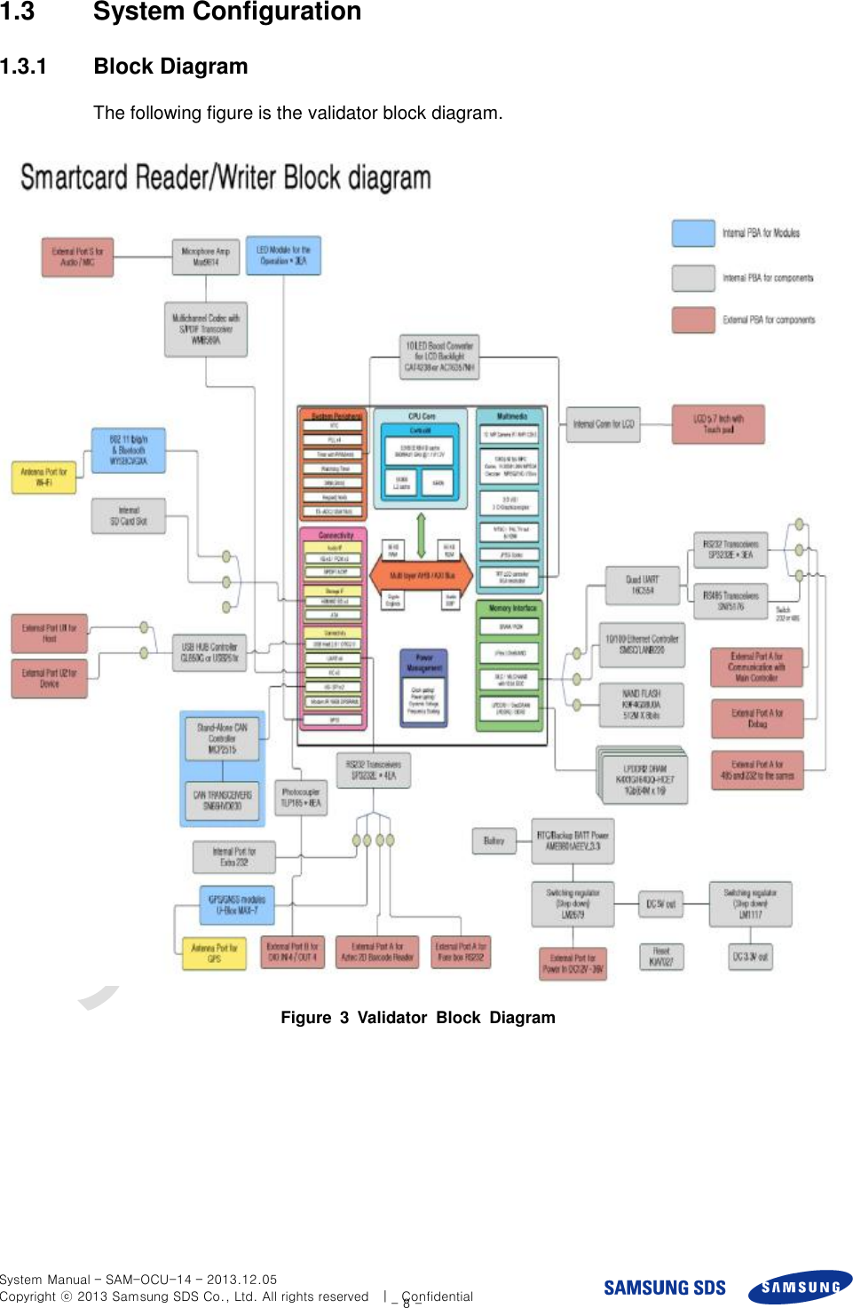
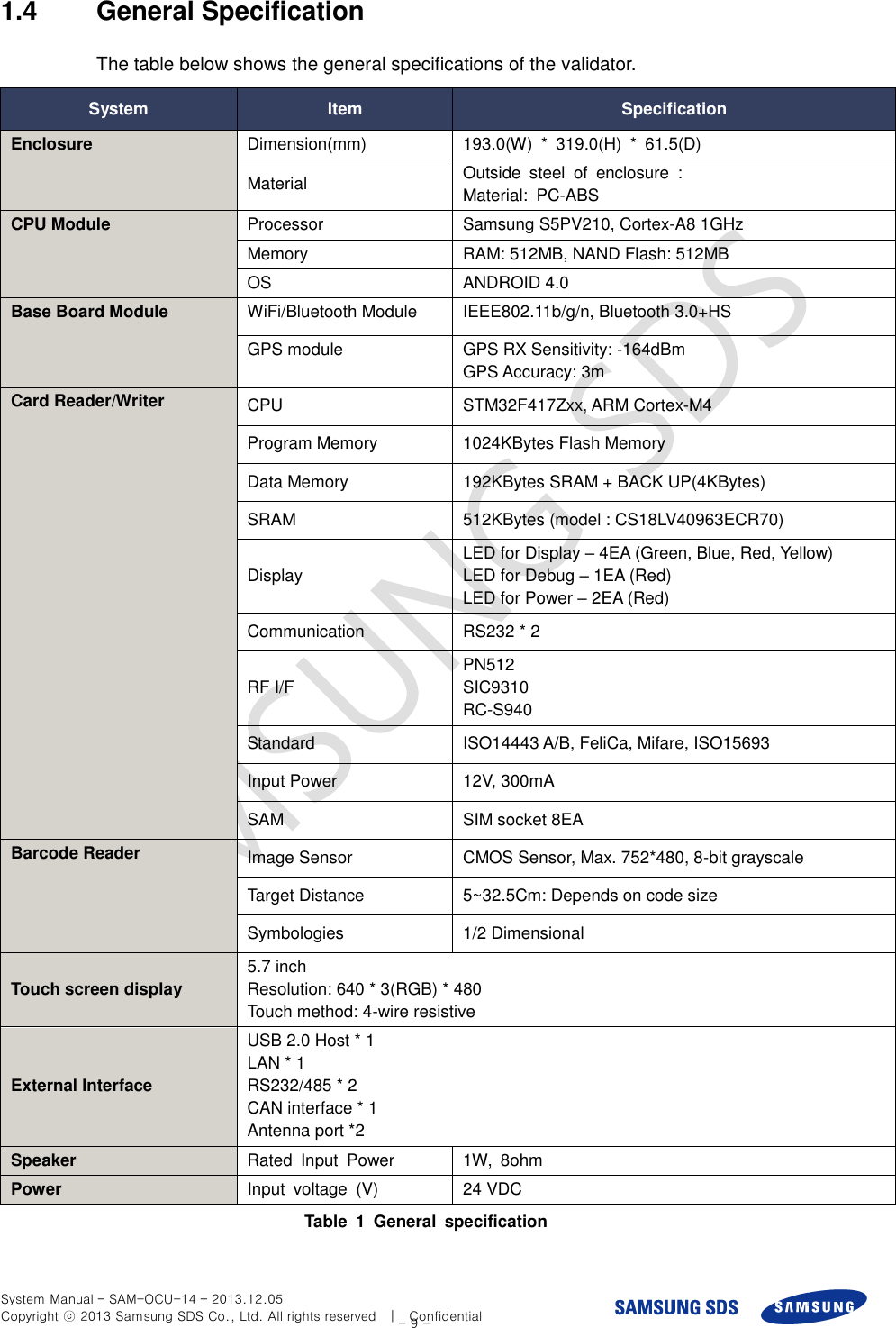
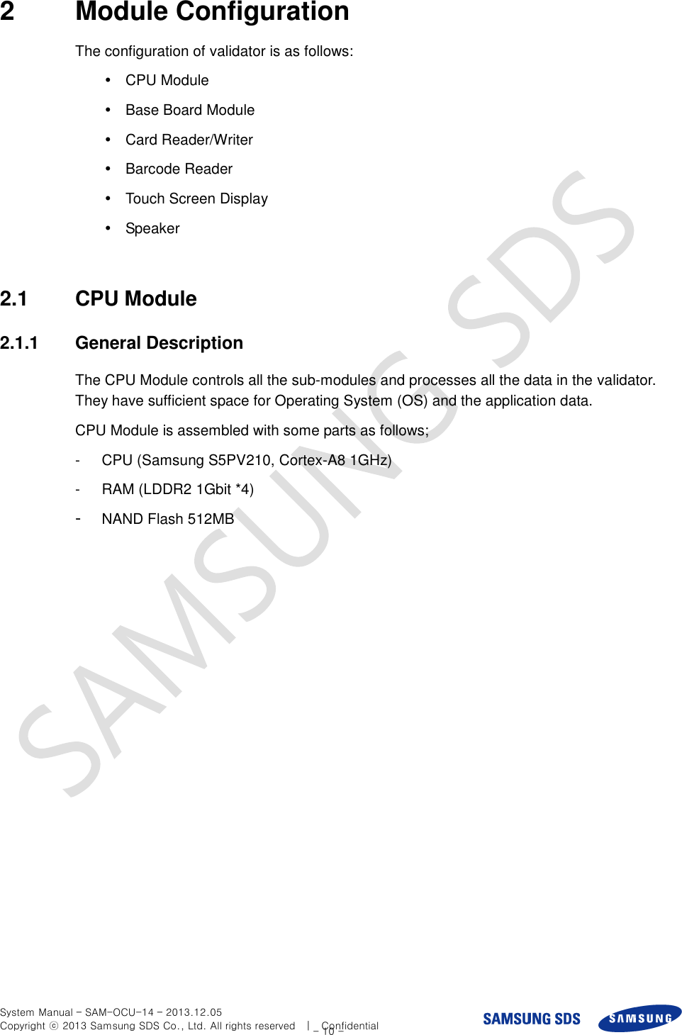
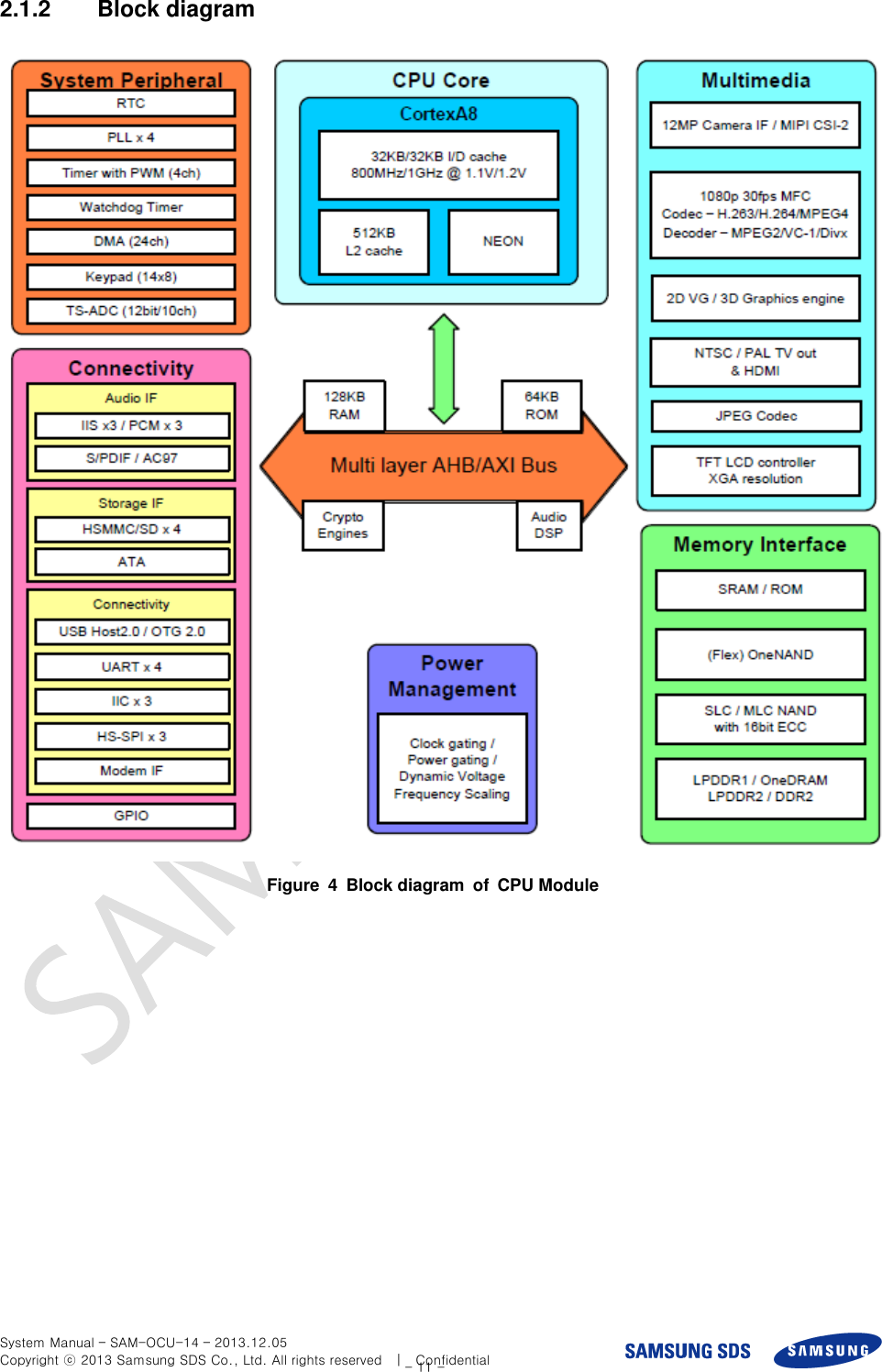
Samsung SDS SAM-CRM-14 SMART VALIDATOR User Manual

Samsung SDS Co., Ltd. SMART VALIDATOR

User Manual

    SMART CARD READER/WRITER SAM-CRM-14   System Manual Ver 1.2        SAM-CRM-14_MANUAL  Rev. 1.2   Dec. 05, 2013       Copyright  ⓒ 2013 Samsung SDS Co., Ltd. All rights reserved. You are strictly prohibited to copy, disclose, distribute, or use this document in part or as a whole for any purposes other than those for which this document is disclosed. This document is copyrighted and contains confidential information and other intellectual property rights of Samsung SDS Co., Ltd. Any unauthorized use, copy, disclosure or distribution constitutes infringement of Samsung SDS’ intellectual property rights.      This equipment complies with FCC radiation exposure limits set forth for an uncontrolled environment.  This equipment should be installed and operated with minimum distance 20cm between the radiator &your body.
 System Manual – SAM-OCU-14 – 2013.12.05 Copyright ⓒ 2013 Samsung SDS Co., Ltd. All rights reserved    |    Confidential - 1 -    Revision History Document Name Smart Card Reader/Writer System Manual Version Date Notice Writer 0.1 1.0 1.1 1.2 2013.06.20 2013.11.17 2013.11.18 2013.12.05 Draft Revision Revision & Translation Revision Kihyun, Kim Dalyoung, Kim Kihyun, Kim Dalyoung, Kim
 System Manual – SAM-OCU-14 – 2013.12.05 Copyright ⓒ 2013 Samsung SDS Co., Ltd. All rights reserved    |    Confidential - 2 -
 System Manual – SAM-OCU-14 – 2013.12.05 Copyright ⓒ 2013 Samsung SDS Co., Ltd. All rights reserved    |    Confidential - 3 - 목   차 Table of Contents 1 OVERVIEW .............................................................................................................................................. - 6 - 1.1 GENERAL DESCRIPTION ....................................................................................................................... - 6 - 1.2 OUTSIDE DIMENSION ........................................................................................................................... - 7 - 1.3 SYSTEM CONFIGURATION .................................................................................................................... - 8 - 1.3.1 Block Diagram ............................................................................................................................ - 8 - 1.4 GENERAL SPECIFICATION ..................................................................................................................... - 9 - 2 MODULE CONFIGURATION ............................................................................................................. - 10 - 2.1 CPU MODULE .................................................................................................................................... - 10 - 2.1.1 General Description .................................................................................................................. - 10 - 2.1.2 Block diagram ........................................................................................................................... - 11 - 2.2 BASE BOARD MODULE ........................................................................................................................ - 12 - 2.2.1 General Description .................................................................................................................. - 12 - 2.2.2 Layout of Base board module .................................................................................................... - 12 - 2.2.3 Wi-Fi/Bluetooth module ............................................................................................................ - 13 - 2.2.4 GPS module ............................................................................................................................... - 13 - 2.3 CARD READER/WRITER ..................................................................................................................... - 14 - 2.3.1 General Description .................................................................................................................. - 14 - 2.3.2 Specification .............................................................................................................................. - 14 - 2.4 TOUCH SCREEN DISPLAY ................................................................................................................... - 16 - 2.4.1 General Description .................................................................................................................. - 16 - 2.4.2 Layout........................................................................................................................................ - 16 - 2.4.3 LCD display specification ......................................................................................................... - 17 - 2.4.4 Touch panel specification .......................................................................................................... - 18 - 2.5 BARCODE READER ............................................................................................................................. - 19 - 2.5.1 General Description .................................................................................................................. - 19 - 2.5.2 Layout........................................................................................................................................ - 19 - 2.5.3 Specification .............................................................................................................................. - 19 - 2.6 SPEAKER ............................................................................................................................................ - 20 - 2.6.1 General Description .................................................................................................................. - 20 - 2.7 CONNECTOR AND POWER SWITCH ...................................................................................................... - 21 - 2.7.1 Signal & Power connector ........................................................................................................ - 21 - 2.7.2 LAN connector .......................................................................................................................... - 21 - 2.7.3 Power switch & Fuse holder ..................................................................................................... - 22 - 2.8 CONNECTION DIAGRAM ..................................................................................................................... - 23 -
 System Manual – SAM-OCU-14 – 2013.12.05 Copyright ⓒ 2013 Samsung SDS Co., Ltd. All rights reserved    |    Confidential - 4 - 2.8.1 Rear Cover connector – PWR ................................................................................................... - 24 - 2.8.2 Rear Cover connector – SIGNAL_1 .......................................................................................... - 24 - 2.8.3 Rear Cover connector – SIGNAL_2 .......................................................................................... - 25 - 2.8.4 Rear Cover connector – DIO .................................................................................................... - 25 - 2.9 OPERATION & USAGE ........................................................................................................................ - 26 -
 System Manual – SAM-OCU-14 – 2013.12.05 Copyright ⓒ 2013 Samsung SDS Co., Ltd. All rights reserved    |    Confidential - 5 - List of Tables  TABLE 1 GENERAL SPECIFICATION ....................................................................................................................... - 9 - TABLE 2 SPECIFICATION OF GPS MODULE .......................................................................................................... - 13 - TABLE 3 SPECIFICATION OF CARD READER/WRITER ........................................................................................... - 15 - TABLE 4 SPECIFICATION OF LCD DISPLAY ......................................................................................................... - 18 - TABLE 5 SPECIFICATION OF TOUCH PANEL ......................................................................................................... - 18 - TABLE 6 SPECIFICATION OF BARCODE READER .................................................................................................. - 19 - TABLE 7 SPECIFICATION OF SPEAKER ................................................................................................................. - 20 - TABLE 8 SPECIFICATION OF PWR CONNECTOR ................................................................................................... - 20 - TABLE 9 SPECIFICATION OF SIGNAL_1 CONNECTOR........................................................................................... - 20 - TABLE 10 SPECIFICATION OF SIGNAL_2 CONNECTOR ........................................................................................ - 20 - TABLE 11 SPECIFICATION OF DIO CONNECTOR................................................................................................... - 20 -   List of Figures  FIGURE 1 DRAWING OF VALIDATOR ...................................................................................................................... - 6 - FIGURE 2 OUTSIDE DIMENSION ............................................................................................................................ - 7 - FIGURE 3 VALIDATOR BLOCK DIAGRAM .............................................................................................................. - 8 - FIGURE 4 BLOCK DIAGRAM OF CPU MODULE ................................................................................................... - 11 - FIGURE 5 TOP LAYOUT OF BASE BOARD MODULE (EXAMPLE) ........................................................................... - 12 - FIGURE 6 BOTTOM LAYOUT OF BASE BOARD MODULE (EXAMPLE) .................................................................... - 12 - FIGURE 7 LAYOUT OF LCD DISPLAY .................................................................................................................. - 16 - FIGURE 8 LAYOUT OF TOUCH PANEL .................................................................................................................. - 17 - FIGURE 9 LAYOUT OF BARCODE READER ........................................................................................................... - 19 - FIGURE 10 LAYOUT OF SPEAKER ........................................................................................................................ - 20 - FIGURE 11 CONNECTOR LAYOUT OF REAR COVER ............................................................................................ - 23 - FIGURE 12 LED CONFIGURATION OF REAR COVER ............................................................................................. - 26 - FIGURE 13 LED OF CARD PROCESSING .............................................................................................................. - 26 -
 System Manual – SAM-OCU-14 – 2013.12.05 Copyright ⓒ 2013 Samsung SDS Co., Ltd. All rights reserved    |    Confidential - 6 - 1  Overview 1.1  General Description The validator is installed on the bus and has a role of fare collection. It has a RF card reader/writer which comply the EMV standard and ISO 14443 Type A. The validator has a 5.7” touch screen display for passenger interface. It is compatible to a peripheral device through a multiple external interface such as Wi-Fi, Bluetooth and etc. This document informs and defines each module and specification of validator.    Figure  1  Drawing  of  validator
 System Manual – SAM-OCU-14 – 2013.12.05 Copyright ⓒ 2013 Samsung SDS Co., Ltd. All rights reserved    |    Confidential - 7 - 1.2  Outside Dimension     Figure  2  Outside dimension
 System Manual – SAM-OCU-14 – 2013.12.05 Copyright ⓒ 2013 Samsung SDS Co., Ltd. All rights reserved    |    Confidential - 8 - 1.3  System Configuration 1.3.1  Block Diagram The following figure is the validator block diagram.  Figure  3  Validator  Block  Diagram
 System Manual – SAM-OCU-14 – 2013.12.05 Copyright ⓒ 2013 Samsung SDS Co., Ltd. All rights reserved    |    Confidential - 9 - 1.4  General Specification The table below shows the general specifications of the validator. System Item Specification Enclosure Dimension(mm) 193.0(W)  *  319.0(H)  *  61.5(D) Material Outside  steel  of  enclosure  : Material:  PC-ABS   CPU Module Processor Samsung S5PV210, Cortex-A8 1GHz Memory RAM: 512MB, NAND Flash: 512MB OS ANDROID 4.0 Base Board Module WiFi/Bluetooth Module IEEE802.11b/g/n, Bluetooth 3.0+HS GPS module GPS RX Sensitivity: -164dBm GPS Accuracy: 3m Card Reader/Writer CPU STM32F417Zxx, ARM Cortex-M4 Program Memory 1024KBytes Flash Memory   Data Memory 192KBytes SRAM + BACK UP(4KBytes) SRAM 512KBytes (model : CS18LV40963ECR70) Display LED for Display – 4EA (Green, Blue, Red, Yellow) LED for Debug – 1EA (Red) LED for Power – 2EA (Red) Communication RS232 * 2 RF I/F PN512 SIC9310 RC-S940 Standard ISO14443 A/B, FeliCa, Mifare, ISO15693 Input Power 12V, 300mA SAM SIM socket 8EA Barcode Reader Image Sensor CMOS Sensor, Max. 752*480, 8-bit grayscale Target Distance 5~32.5Cm: Depends on code size Symbologies 1/2 Dimensional Touch screen display 5.7 inch Resolution: 640 * 3(RGB) * 480 Touch method: 4-wire resistive External Interface USB 2.0 Host * 1 LAN * 1 RS232/485 * 2 CAN interface * 1 Antenna port *2 Speaker Rated  Input  Power 1W,  8ohm Power Input  voltage  (V) 24 VDC Table  1  General  specification
 System Manual – SAM-OCU-14 – 2013.12.05 Copyright ⓒ 2013 Samsung SDS Co., Ltd. All rights reserved    |    Confidential - 10 - 2  Module Configuration The configuration of validator is as follows:     CPU Module   Base Board Module   Card Reader/Writer   Barcode Reader   Touch Screen Display   Speaker  2.1  CPU Module 2.1.1  General Description The CPU Module controls all the sub-modules and processes all the data in the validator. They have sufficient space for Operating System (OS) and the application data.   CPU Module is assembled with some parts as follows; -  CPU (Samsung S5PV210, Cortex-A8 1GHz) -  RAM (LDDR2 1Gbit *4) -  NAND Flash 512MB
 System Manual – SAM-OCU-14 – 2013.12.05 Copyright ⓒ 2013 Samsung SDS Co., Ltd. All rights reserved    |    Confidential - 11 - 2.1.2  Block diagram  Figure  4  Block diagram  of  CPU Module
 System Manual – SAM-OCU-14 – 2013.12.05 Copyright ⓒ 2013 Samsung SDS Co., Ltd. All rights reserved    |    Confidential - 12 - 2.2  Base board module 2.2.1  General Description Base board module performs major functions of validator device controlling. The Wi-Fi/BT module, CAN module and etc. are installed on the base board. 2.2.2  Layout of Base board module  Figure  5  Top Layout  of  Base board module  (Example)  Figure  6  Bottom Layout  of  Base board module  (Example)
 System Manual – SAM-OCU-14 – 2013.12.05 Copyright ⓒ 2013 Samsung SDS Co., Ltd. All rights reserved    |    Confidential - 13 - 2.2.3  Wi-Fi/Bluetooth module The validator has the Wi-Fi/Bluetooth module to communicate with the server (in the garage) and peripheral devices. The key features are as below;   IEEE802.11b/g/n standard conformity, BT3.0,2.1+EDR   Low standby current (with advanced power save and sleep mode)   Transmit speed : 11/5.5/2/1 Mbps(11b), 54/48/36/24/18/12/9/6 Mbps(11g), 150~6.5 Mbps (11n)   Channel Number : 1 to 13 channel (11bg), 79 channel (BT)   Interface : SDIO   Built-in EEPROM, 2G-PA, Crystal, BPF   Security: WEP (64/128), TKIP, AES, WPA/WPA2, WAPI   Small Outline: 9.0 x 8.8 x 1.35(Max) mm   Package: Metal case package   Utilizes 88W8787 IC  RoHS Conformity  2.2.4  GPS module The specification of GPS module is as below. Item Specification RX Sensitivity -164dBm Cold start autonomous -147dBm Hot start autonomous -161dBm Tracking mode -166dBm Accuracy 3m TTFF from cold start 42 sec TTFF from warm start 30 sec TTFF from hot start 1.8 sec Table  2  Specification  of  GPS module
 System Manual – SAM-OCU-14 – 2013.12.05 Copyright ⓒ 2013 Samsung SDS Co., Ltd. All rights reserved    |    Confidential - 14 - 2.3  Card Reader/Writer 2.3.1  General Description Card Reader/Writer is a high-end RF reader and it is the world first device which supports all three specification as following, (1) Contactless card spec_Mifare, ISO14443 Standard A/B, (2)Payment spec_Paywave, Paypass, JSMART, American Express and (3) EMVCo Type Approval Contact less Level 1 , NFC forum spec complaint.   It also has 8(EA) of SIM slot for secure communication, RS-232(2ea) as interface method.    Purpose (Use) It is multi-purpose smartcard reader mainly use for credit card transaction at auto-gate at subway station or automatic ticket vending machine    Communication & Operation It controls credit card transaction by sending command to Host Controller via RS232. This terminal operates LED and Buzzer of the transaction operating and result. The operation of LED & Buzzer can be different by each specification (refer to the Paypass, JSMART, American Express specification for detail information)      RF interface Conrtactless card spec_Mifare,   ISO14443 Standard A/B    SAM interface It is designed to capable of communicating SAM (ISO 7816 ) by attaching extended parts for future use.    2.3.2  Specification System Item Specification Card Reader/Writer CPU STM32F417Zxx, ARM Cortex-M4 Program Memory 1024KBytes Flash Memory   Data Memory 192KBytes SRAM + BACK UP(4KBytes) SRAM 512KBytes (model : CS18LV40963ECR70) Display LED for Display – 4EA (Green, Blue, Red, Yellow) LED for Debug – 1EA (Red) LED for Power – 2EA (Red)
 System Manual – SAM-OCU-14 – 2013.12.05 Copyright ⓒ 2013 Samsung SDS Co., Ltd. All rights reserved    |    Confidential - 15 - System Item Specification Communication RS232 * 2 RF I/F PN512 SIC9310 RC-S940 Standard ISO14443 A/B, FeliCa, Mifare, ISO15693 Input Power 12V, 300mA SAM SIM socket 8EA Switch Case open switch (PCB tamper) Table  3  Specification of Card reader/writer
 System Manual – SAM-OCU-14 – 2013.12.05 Copyright ⓒ 2013 Samsung SDS Co., Ltd. All rights reserved    |    Confidential - 16 - 2.4  Touch Screen Display 2.4.1  General Description The Touch screen display is a color graphic touch screen (5.7” inch TFT LCD) that allows passenger to input their selection. The Touch screen display is positioned ergonomically for passenger to operate easily. 2.4.2  Layout  Figure  7  Layout of LCD display
 System Manual – SAM-OCU-14 – 2013.12.05 Copyright ⓒ 2013 Samsung SDS Co., Ltd. All rights reserved    |    Confidential - 17 -  Figure  8  Layout of Touch panel  2.4.3  LCD display specification Item Specification Screen Diagonal 5.7 inch Active Area 115.2(H) x 86.4(V) (mm) Pixels HxV 640 x 3(RGB) x 480 Pixel Pitch 0.18 x 0.18 (mm) Pixel Arrangement R.G.B Vertical Stripe Display Mode TN, Normally White Nominal Input Voltage VDD 3.3 typ. (Volt) Typical Power Consumption 3.74W (LCD:0.5W/LED BLU:3.24W) @ All black pattern, Full Load and VLED=12V Weight 150g(typ.), 165g(max.) Physical Size 144.0(H) x 104.6(V) x 12.3(D)(typ.) (mm) Electrical Interface CMOS 6-bit Parallel RGB Surface Treatment Anti-Glare, Hardness 3H Support Color 262K colors
 System Manual – SAM-OCU-14 – 2013.12.05 Copyright ⓒ 2013 Samsung SDS Co., Ltd. All rights reserved    |    Confidential - 18 - Item Specification The most suitable view angle 12 o’clock Temperature Range Operating: -30℃~+85℃ Storage: -30℃~+85℃ RoHS Compliance RoHS Compliance Table  4  Specification  of  LCD Display  2.4.4  Touch panel specification Item Specification Glass THK 1.1mm Film type Non-glare Tail FPC (Ni+Au) Method 4-wire resistive touch Table  5  Specification  of  Touch panel
 System Manual – SAM-OCU-14 – 2013.12.05 Copyright ⓒ 2013 Samsung SDS Co., Ltd. All rights reserved    |    Confidential - 19 - 2.5  Barcode Reader 2.5.1  General Description The validator has the barcode reader to read the barcode type ticket (1D or 2D). 2.5.2  Layout  Figure  9  Layout of Barcode reader  2.5.3  Specification Item Specification Image Sensor CMOS Sensor, Max. 752*480, 8-bit grayscale Target Distance   5~32.5cm: Depends on code size. Viewing Angle Wide  ±53º, Standard  ±40º Aiming Pattern Laser Aiming Ambient Lighting Total darkness to full sunlight Directions 360  º  omni-directional 1 Dimensional Code11, Code32, Code39, Code93, Code128, UPC/JAN/EAN, Codabar, Interleaved 2 of 5, STF, RSS14, RSS Limited, RSS Truncated 2 Dimensional PDF-417, Data Matrix, QR Code (including Chinese QR) OCR Application-specific OEM only Operating Temperature -10ºC to +50ºC (-14ºF to 122ºF) Storage Temperature -20ºC to +60ºC (-4ºF to 140ºF) Shock Multiple 4ft/1.2M drop to concrete Humidity 0 to 95% Certifications FCC Class A & CE Table  6  Specification  of  Barcode reader
 System Manual – SAM-OCU-14 – 2013.12.05 Copyright ⓒ 2013 Samsung SDS Co., Ltd. All rights reserved    |    Confidential - 20 - 2.6  Speaker 2.6.1  General Description The speaker is installed in the validator. It makes a sound for driver’s recognition.  Figure  10  Layout of Speaker  Items Description Rated Input Power 1.0W (Max. 1.5W) Impedance 8±15%(Ohm) Output SPL @ 0.1W/0.1M 87±2dB Resonant frequency 800±20% Hz Magnet size (mm) 11.5 * 1.5 Weight 10g Dimension (mm) 40(W) * 20(H) * 8.2(D) Table  7  Specification  of  Speaker
 System Manual – SAM-OCU-14 – 2013.12.05 Copyright ⓒ 2013 Samsung SDS Co., Ltd. All rights reserved    |    Confidential - 21 - 2.7  Connector and Power switch 2.7.1  Signal & Power connector   2.7.2  LAN connector
 System Manual – SAM-OCU-14 – 2013.12.05 Copyright ⓒ 2013 Samsung SDS Co., Ltd. All rights reserved    |    Confidential - 22 - 2.7.3  Power switch & Fuse holder
 System Manual – SAM-OCU-14 – 2013.12.05 Copyright ⓒ 2013 Samsung SDS Co., Ltd. All rights reserved    |    Confidential - 23 - 2.8  Connection Diagram  Figure  11  Connector Layout of Rear Cover
 System Manual – SAM-OCU-14 – 2013.12.05 Copyright ⓒ 2013 Samsung SDS Co., Ltd. All rights reserved    |    Confidential - 24 - 2.8.1  Rear Cover connector – PWR      Pin No Name Description Connector Option 1 PWR DC_IN DC POWER IN   24V 2 PWR DC_IN     3 GND GND 4 GND GND  Table  8  Specification  of  PWR Connector  2.8.2  Rear Cover connector – SIGNAL_1   Pin No Name Description Connector Option 1 RXD Comm RS232 Comm 2 TXD Comm     3 GND Comm 4 RXD GND 5 TXD Comm 6 GND Comm 7 485_A Comm RS 485 Comm 8 485_B Comm 9 485_A RS232 & 485 RS232 or 485 (Optional) 10 485_B RS232 & 485 Table  9  Specification  of  SIGNAL_1 Connector
 System Manual – SAM-OCU-14 – 2013.12.05 Copyright ⓒ 2013 Samsung SDS Co., Ltd. All rights reserved    |    Confidential - 25 - 2.8.3  Rear Cover connector – SIGNAL_2   Pin No Name Description Connector Option 1 VDD DC_OUT 3.3V RS232 Comm 2 RXD Comm 3 TXD Comm 4 GND GND 5 GND GND 6 VDD DC_OUT 5.0V 7 485_A Comm RS 485 Comm 8 485_B Comm 9 485_A RS232 & 485 RS232 or 485 (Optional) 10 485_B RS232 & 485 Table  10  Specification  of  SIGNAL_2 Connector  2.8.4  Rear Cover connector – DIO   Pin No Name Description Connector Option 1 VDD VDD_IN0 Digital In/Out 2 ports 2 DIO GPIO_IN0   3 DIO GPIO_OUT0 4 GND GND0 5 VDD VDD_IN1 6 DIO GPIO_IN1 7 DIO GPIO_OUT1 8 GND GND1 9 CANH CAN Comm   10 CANL CAN Comm 11 N.C.   12 N.C  Table  11  Specification  of  DIO Connector
 System Manual – SAM-OCU-14 – 2013.12.05 Copyright ⓒ 2013 Samsung SDS Co., Ltd. All rights reserved    |    Confidential - 26 - 2.9  Operation & Usage 1.  Turn on the validator, check the android OS booting by the LCD display. After boot-up, the operator can use the validator. 2.  When the validator turned on, the card r/w makes beep sound 1 time. 3.  There are three (3) colors LED (Red, Blue, and Green) on the rear cover. The LED color can be configured by setting.  Figure  12 LED configuration of rear cover  4.  There are four (4) LED on the front cover indicate the card process according to the EMV process like as below; -  Ready LED (Blue color) -  Process LED (Yellow color) -  Success LED (Green color) -  Error LED (Red color)  Figure  13 LED of Card processing  5.  The LCD display has a resistive touch panel for operator to operate the validator by using his finger.
 System Manual – SAM-OCU-14 – 2013.12.05 Copyright ⓒ 2013 Samsung SDS Co., Ltd. All rights reserved    |    Confidential - 27 - 6.  There are USB port and External Micro SD card slot on the right side of validator.     7.  There are Digital In/Output port, Serial communication port and LAN (Ethernet) port on the rear cover of validator. So, it supports variable interface. 8.  The validator has audio feedback to support the announcement for passenger.      FCC STATEMENT CAUTION:  Changes  or  modifications  not  expressly  approved  by  the  party  responsible  for compliance could void the user's authority to operate the equipment.    Note: This equipment has been tested and found to comply with the limits for a Class A digital device, pursuant to part 15 of the FCC   Rules. These limits are designed  to  provide  reasonable  protection   against  harmful  interference  when the  equipment  is  operated  in  a  commercial  environment.  This  equipment generates,  uses,  and  can  radiate  radio  frequency  energy  and,  if  not  installed and  used  in  accordance  with  the  instruction  manual,  may  cause  harmful interference  to  radio  communications.  Operation  of  this  equipment  in  a residential area is likely  to cause  harmful interference in which case the user will be required to correct the interference at his own expense.   Modifications not expressly approved by the manufacturer could void the user's authority to operated the equipment under FCC rules.
 System Manual – SAM-OCU-14 – 2013.12.05 Copyright ⓒ 2013 Samsung SDS Co., Ltd. All rights reserved    |    Confidential - 28 -  Tel : +82-2-3429-2114 E-mail : sdspr@samsung.com http://www.sds.samsung.co.kr Copyright ⓒ 2013 Samsung SDS Co., Ltd. All rights reserved    |    Confidential Thank You

Navigation menu