Samsung SDS SHN-WDD510 Digital door lock User Manual
Samsung SDS Co., Ltd. Digital door lock Users Manual
UserManual.wiki
>
Samsung SDS
>
SHN WDD510 User Manual
Users Manual
Navigation menu
Upload a User Manual
Namespaces
Wiki Guide
HTML
PDF
Info
Views
User Manual
Discussion / Help
Navigation
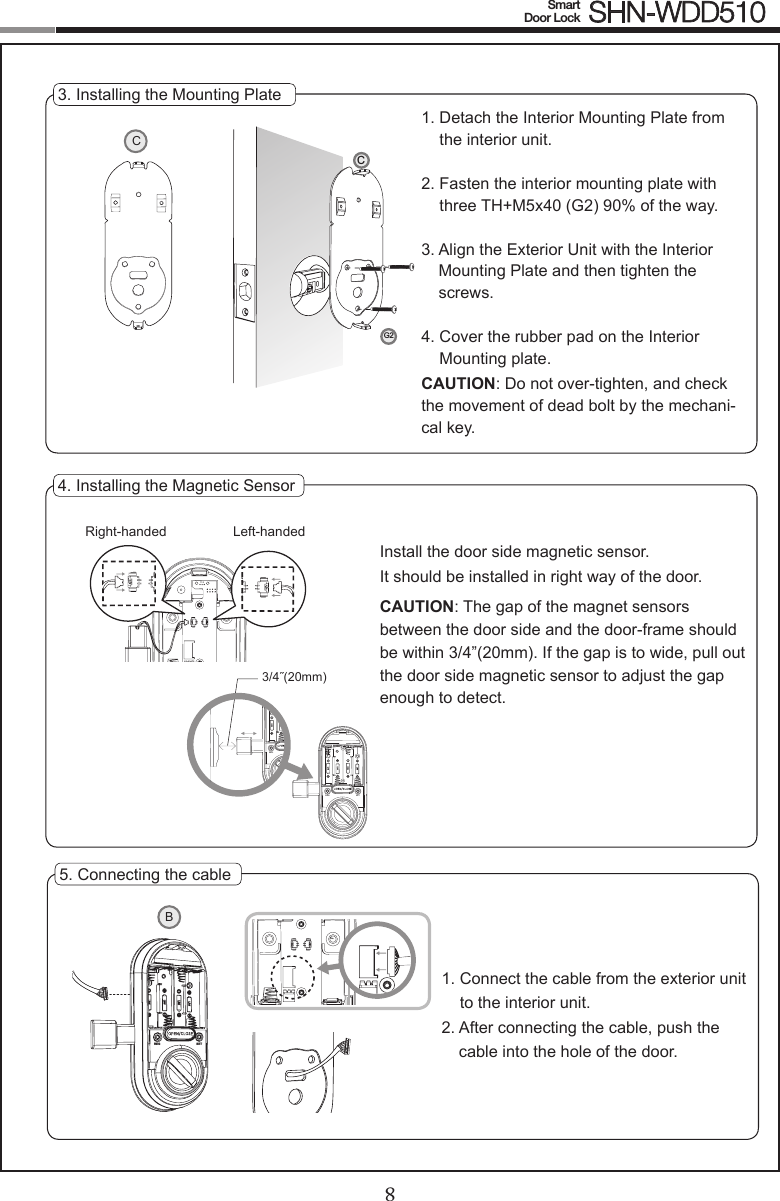
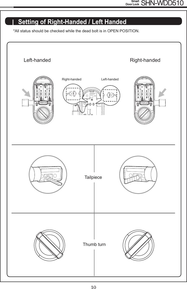
![89Smart Door Lock SHN-WDD5106. Fix Screw for the Interior Unit1. Before installing the interior unit, check the direction of the thumb turn while the dead bolt is in the OPEN POSITION.2. Open the battery cover.3. Align the Interior Unit on to the Interior Mounting Plate, and attach it with 4 screws.CAUTION: Check the movement of the dead bolt by the thumb turn.7. Final Check1. Install 4 batteries. A Melody will sound when all 4 batteries are installed correctly.2. Close the door to detect the magnetic sensor. You can hear the beep sound when the magnetic sensor detects. After that, press [OPEN/CLOSE] button to check whether the dead bolt works properly.3. Stick the magnetic sensor with attention on the distance.CAUTION: The gap between the door side and the door-frame magnetic sensors should be close enough to be detected.OPTION : Connection for Video IntercomConnect the cable of video intercom to the Interior Unit.SHN-WDD510 receives 1 second of dry contact signal to open the door remotely. It is normally compatible with SHT-3006 and other Samsung Video Intercom systems.Dry Contact Signal3/4˝(20mm)123CREG SETBG3SETREG SETREGLeft-handed Right-handedSETREG SETREGB JREG SETSETREGREG](https://usermanual.wiki/Samsung-SDS/SHN-WDD510/User-Guide-2411246-Page-9.png)
![1011Smart Door Lock SHN-WDD510PROGRAMMING REG SETTouchscreenEmergency Key Hole Exterior InteriorBattery CoverOpen/Close ButtonThumbturn LeverRestart ButtonCard ReaderMagnetic Sensor[REG] Button[SET] ButtonNetwork Module SlotPrivacy Mode IndicatorLow Battery IndicatorSymbols Description Symbols DescriptionTouch the [Touchscreen]. Press the [ ] button. It is used to complete number entry.SET: Used for setting the Additional Functions.Mstr PINEnter the Master PIN Code (4~10 digits). Factory Default: 1234REG: Open the battery cover of the Interior Unit and press the [REG] button. It is used to begin or exit the Program mode.REG3: Press the [REG] button for 3 seconds.Press the Number buttons.Enter the User PIN Code (4~10 digits).Repeat the process inside the rectangle.| Programming FeaturesS3R](https://usermanual.wiki/Samsung-SDS/SHN-WDD510/User-Guide-2411246-Page-11.png)
![12Smart Door Lock SHN-WDD51013Symbols Description Symbols DescriptionTouch the Card reader with the User Card.Press the [OPEN/CLOSE] button. U NoEnter the User Number. Can be set from 1 to 100.OPEN / CLOSEIndicator Lamp : Indicates the operational status when the Card is being read or the lock is in operation.Intrusion Detection Function : When the Interior Unit is forcibly detached while the door is locked, it is detected by the magnetic sensor and an alarm is sounded. (The function is not activated when the magnet is not used.)The Intrusion Detection function is a basic function and cannot be enabled or disabled.Locking Mode (Auto/Manual) : You can enable or disable the function for locking the door automatically when it is closed. The factory default is ‘Auto mode’. - Auto: The door is locked automatically 2 seconds after it is closed. However, it does not function if the magnet is not used or the batteries are completely discharged. - Manual: When the door does not lock automatically when it is closed, touch the [Touchscreen] or the [OPEN/CLOSE] button on the Interior Unit will lock the door. Low Voltage Indicator : Refers to the state when the operating voltage of the lock is lower than the standard voltage, and activates the Low Voltage Alarm (“Please change the batteries”) to indi-cate that the batteries need to be replaced. Use the Emergency Key when the batteries are com-pletely discharged. In case of the low voltage, the low-votage LED ickers when using doorlock.Magnetic Sensor : Detects the opening and closing of the door.Thumbturn Lever : When the batteries are completely discharged, this device is used to me-chanically lock or unlock the door from inside.Master PIN Code : You can enter only one Master PIN (4-10 digits) Code. You can register the User PIN Codes/Cards after authenticating with the Master PIN (4-10 digits) Code. You can open the door with the Master PIN Code, and the factory default is ‘1234’.OPEN/CLOSE Button : A one-touch button to open the locked door. (It is also used to lock the door from inside in the Manual locking mode.)Privacy Mode : Privacy Mode prevents the lock from being unlocked from the outside. You can enable it by using the [OPEN/CLOSE] button. The Privacy Mode LED on, when Privacy Mode func-tion is activated.Random Security Function : This mode prevents the disclosure of the PIN Code by entering the PIN Code after authenticating 2 arbitrarily selected numbers. When the buttons for 2 arbitrarily selected numbers are illuminated, pressing the 2 illuminated buttons illuminates the whole touch-screen. You can enable or disable the Random Security function. This function is enabled by de-fault.Registration Button : This button is used to change Master PIN Code/User PIN Codes/User | Denitions](https://usermanual.wiki/Samsung-SDS/SHN-WDD510/User-Guide-2411246-Page-12.png)
![1213Smart Door Lock SHN-WDD510Status IndicatorsPrivacy Mode IndicatorLow Battery IndicatorCards or the lock settings. It is found below the battery cover of the Interior Unit. The length of time the [REG] button is pressed varies depending on the function. Resetting : Deletes all registered information and restores the factory default. After resetting, change the Master PIN Code for security.Restart Button : This button resets the lock when the lock stops functioning. Registered informa-tion is not deleted.Set Button : Used for setting the Additional Functions. It is found below the battery cover of the Interior Unit. Sound Setting : The volume during the input of numbers and opening or locking of the door can be set from Level 0 ~ Level 2. The sound is muted at Level 0 and is at maximum volume at Level 2. The registration mode operates at Level 1 regardless of the sound setting.User Card : You can register up to 100 User Cards including the User PIN Codes. You can open the door with a User Card.User Number : It is the same number as the registered user’s address and can be set from 1 to 100. The User Number should be managed with caution as it is used to register or delete User PIN Codes/Cards.User PIN Code : You can register up to 100 User PIN Codes (4-10 digits) including the User Cards. You can open the door with a User PIN Code.Network Module : After registering Network Module, Smart doorlock is able to be remotely-con-trolled via Gateway(optional).](https://usermanual.wiki/Samsung-SDS/SHN-WDD510/User-Guide-2411246-Page-13.png)
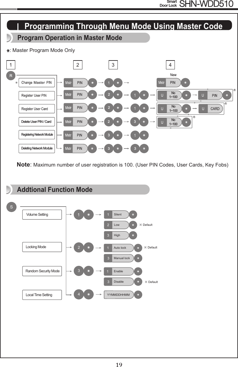
![14Smart Door Lock SHN-WDD51015Touch the [Touchscreen].Touch lock with back of hand or ngers to acti-vate.Open the battery cover of the Interior Unit and press the [REG] button briey.When the touchscreen is illuminated, enter the current Master PIN Code (default is ‘1234’) and press the [ ] button.Press the [ ] button after pressing the [1] button.Enter the new Master PIN Code and press the [ ] button.Note: Master PIN Code must be 4~10 digits.REG SETRNo1~100No1~100No1~100No1~100R222333No1~100No1~100No1~100No1~100R222333Lock ActivationChanging the Master PIN Code](https://usermanual.wiki/Samsung-SDS/SHN-WDD510/User-Guide-2411246-Page-14.png)
![1415Smart Door Lock SHN-WDD510Registering a User PIN Code/ CardOpen the battery cover of the Interior Unit and press the [REG] button briey.When the touchscreen is il-luminated, enter the current Master PIN Code (default is ‘1234’) and press the [ ] button.Press the [ ] button after pressing the [2] button.Enter a User Number(1~ 100) to register the User PIN Code and press the [ ] button.*Choose a User Number that has not already been used.**If don’t enter a User Number and press (0) when registering, the User Number is sequential-ly assigned on the emprty User Number from 1 to 100.Enter a new User PIN Code and press [ ] button.Touch the Card reader with the Card to register.Note: User PIN Code must be 4~10 digits.Enter another User Num-ber or press the [REG] but-ton to quit. REG SETREG SETPress the [ ] button after pressing the [1] button.No1~100No1~100No1~100No1~100R222333No1~100No1~100No1~100No1~100R222333| Managing User PIN Code/ Card](https://usermanual.wiki/Samsung-SDS/SHN-WDD510/User-Guide-2411246-Page-15.png)
![16Smart Door Lock SHN-WDD51017Deleting User PIN Code / User CardEnter the User Number (1 to 100) and press the [ ] button. Open the battery cover of the Interior Unit and press the [REG] button briey.When the touchscreen is il-luminated, enter the current Master PIN Code (default is ‘1234’) and press the [ ] button.Press the [ ] button after pressing the [2] button.REG SETPress the [ ] button after pressing the [3] but-ton.No1~100No1~100No1~100No1~100R222333No1~100No1~100No1~100No1~100R222333No1~100No1~100No1~100No1~100R222333Enter another User Num-ber or press the [REG] but-ton to quit. REG SET](https://usermanual.wiki/Samsung-SDS/SHN-WDD510/User-Guide-2411246-Page-16.png)
![1617Smart Door Lock SHN-WDD510Open the battery cov-er of the Interior Unit and press the [REG] button briey.When the touchscreen is illuminated, enter the current Master PIN Code (default is ‘1234’) and press the [ ] button.Press the [ ] button after pressing the [3] button.REG SETNote: After registering Network Module, Smart doorlock is able to be remotely- controlled via Gateway(optional).| Managing Network ModuleRegistering Network ModuleDeleting Network ModulePress the [ ] button after pressing the [1] button.RNo1~100No1~100No1~100No1~100R222333No1~100No1~100No1~100No1~100R222333No1~100No1~100No1~100No1~100R222333Open the battery cov-er of the Interior Unit and press the [REG] button briey.When the touchscreen is illuminated, enter the current Master PIN Code (default is ‘1234’) and press the [ ] button.Press the [ ] button after pressing the [3] button.REG SETPress the [ ] button after pressing the [3] button.RNo1~100No1~100No1~100No1~100R222333No1~100No1~100No1~100No1~100R222333No1~100No1~100No1~100No1~100R222333](https://usermanual.wiki/Samsung-SDS/SHN-WDD510/User-Guide-2411246-Page-17.png)
![18Smart Door Lock SHN-WDD51019Touch the Card reader with an Access Card| Basic Lock Operation Overview Opening the Door with a PIN CodeOpening the Door with a CardEnter the PIN Code and press the [ ] button. Press the [OPEN/CLOSE] button for 3 seconds while the door is locked.Press the [OPEN/CLOSE] button or turn the Thumbturn lever.Activating Privacy Mode Deactivating Privacy Mode| Privacy Mode FunctionsOPEN / CLOSEOPEN / CLOSE3Touch the [Touchscreen].→The door opens within one second.Touch the [Touchscreen].→The door opens within one second.](https://usermanual.wiki/Samsung-SDS/SHN-WDD510/User-Guide-2411246-Page-18.png)
![20Smart Door Lock SHN-WDD510| Miscellaneous InformationReset to Factory DefaultRestart Function20Note: Restarting does not delete registered information.If there is no response after touching the [Touchscreen], use a pin to press the [Restart] button on the left of the external power contact of the Exterior Unit. REG SETPress the [REG] button for 3 seconds. Enter the current Master PIN Code or “4560852580” and press the [ ] button.Resetting the lock will delete all registered information.Note: All registered Master and user data will be deleted, and the lock will be reset to default settings.Function Factory DefaultMaster PIN Code 1234Volume LowUser PIN Code/Card NoneLocking Mode AutoRandom Security DisabledMISCELLANEOUS](https://usermanual.wiki/Samsung-SDS/SHN-WDD510/User-Guide-2411246-Page-20.png)
![20Smart Door Lock SHN-WDD510When the lock doesn’t function correctly, please check the items below.If you can’t resolve the problem, please contact the nearest service center.Problem Resolution ReferenceThere is no power.● Check if the batteries are inserted in the correct polarity.● Check that the batteries have a full charge.● Check that the Exterior Unit cable has not come loose.-I can’t change the Master PIN Code. ● There was a delay while changing the PIN Code. The touchscreen must be illuminated when changing the PIN Code. Also, after entering the rst digit, the next digit must be entered within 20 seconds. ● Replace the batteries if they are discharged.● Refer to the ‘Changing the Master PIN Code’ section in the user manual and try again. Ensure that the Master PIN Code is 4~10 digits long. Page 14I can’t register the User PIN Code.● The User Number has already been used. Delete the de-sired User Number and re-register.● Ensure that the User PIN Code is 4~10 digits long.Page 15I can’t register the User Card.● The User Number has already been used. Delete the de-sired User Number and re-register.● Ensure that the card is touched to the card reader within 20 seconds of entering the User Number.Page 15I entered the PIN Code and pressed the [ ] button, but the door won’t open. ● Check that the registered PIN Code was entered cor-rectly. ● If the touchscreen illumination turns off while entering the PIN Code, the button input was not registered. Touch the [Touchscreen] to illuminate the touchscreen and enter the PIN Code again from the beginning. (The touchscreen illumination is turned off automatically if there is no input within 5 seconds.)Page 18I can’t unlock the door with my Card. ● The Card is either unregistered or unrecognized. ● The Card must touch the Card reader correctly. Page 18My PIN Code or Card is authenti-cated, but the door won’t open. The lock may be malfunctioning. Please contact service center. -| Troubleshooting21](https://usermanual.wiki/Samsung-SDS/SHN-WDD510/User-Guide-2411246-Page-21.png)
![22Smart Door Lock SHN-WDD51023The door won’t lock automatically when I close it.● Check if Auto Locking is set. When Manual Locking is set, touching the [Touchscreen] locks the door. ● If the door doesn’t lock automatically when Auto Locking is set, then the lock has been installed incorrectly. ● The Auto Locking function is not activated when the bat-teries are completely discharged. Check if the batteries are discharged.Page 19There is no response when I touch the [Touch-screen].● Use a pin to press the hole on the front of the Exterior unit. ● If doing the above does nothing, contact the service center.Page 20](https://usermanual.wiki/Samsung-SDS/SHN-WDD510/User-Guide-2411246-Page-22.png)