Samsung SDS SHN-WDD510 Digital door lock User Manual
Samsung SDS Co., Ltd. Digital door lock Users Manual
Users Manual
Please review all included documentation and use the product as intended. Safety precautions must be
followed to avoid personal injury or property damage.
Samsung Smart Door Lock
User Guide SHN-WDD510

2
Smart
Door Lock SHN-WDD510
3
| Table of Contents
Congratulations on the purchase of your Samsung Smart Door Lock! Your lock has a touch
sensitive number display pad and optionally a 13.56MHz Card reader. Up to 100 users can
be registered to gain access with unique Codes or Access Cards (supports ISO14443A type).
The touchscreen makes it convenient to enter the code and the Randomizer function helps
prevent lockpicking using ngerprint traces on the touchscreen. Other convenient functions
such as Automatic Locking / Sound Setting, etc. provide advanced security and peace of
mind.You can unlock the door using video intercom’s monitor after connecting a Samsung
video intercom. (Refer to page 9 for connection diagram to a video intercom).
| Helpful Tips
| Introduction
Do not attempt to repair the product yourself.
Change your codes regularly to ensure the security of your codes.
Minimize the lock’s exposure to moisture including wet hands and direct contact with
liquids.
Do not exert excessive force or use sharp instrument on the touchscreen.
Insert the batteries according to correct polarity.
When the low-battery warning sounds, replace all batteries immediately.
Do not mix old batteries with new batteries.
Use soft, dry cloth to clean the lock and avoid cleaning with water, alcohol or other
chemicals.
Introduction & Helpful Tips •••••••••••••••••••••••••••••••••••••••••••••••••2
Installation ••••••••••••••••••••••••••••••••••••••••••••••••••••••••••••••3
Components & Tools ••••••••••••••••••••••••••••••••••••••••••••••••••••••3
Door Preparation •••••••••••••••••••••••••••••••••••••••••••••••••••••••4-5
Preparing the parts ••••••••••••••••••••••••••••••••••••••••••••••••••••••••6
Installing Lock •••••••••••••••••••••••••••••••••••••••••••••••••••••••••••7
Setting of Right-Handed / Left Handed ••••••••••••••••••••••••••••••••••••••••10
Programming •••••••••••••••••••••••••••••••••••••••••••••••••••••••••••11
Programming Features & Denitions •••••••••••••••••••••••••••••••••••••••11-14
Changing the Master PIN Code••••••••••••••••••••••••••••••••••••••••••••••14
Managing User Pin Code/ Card••••••••••••••••••••••••••••••••••••••••••• 15-16
Register Network Module ••••••••••••••••••••••••••••••••••••••••••••••••••17
Basic Lock Operation Overview •••••••••••••••••••••••••••••••••••••••••••••18
Privacy Mode Functions •••••••••••••••••••••••••••••••••••••••••••••••••••18
Programming Through Menu Mode Using Master Code •••••••••••••••••••••••••••19
Miscellaneous ••••••••••••••••••••••••••••••••••••••••••••••••••••••••••20
Miscellaneous Information •••••••••••••••••••••••••••••••••••••••••••••••••20
Troubleshooting •••••••••••••••••••••••••••••••••••••••••••••••••••••• 21-22
User Registration Table •••••••••••••••••••••••••••••••••••••••••••••••••••23
Product Specications ••••••••••••••••••••••••••••••••••••••••••••••••••••24
Warranty ••••••••••••••••••••••••••••••••••••••••••••••••••••••••••• 25-26
Drilling Template ••••••••••••••••••••••••••••••••••••••••••••••••••••• 27-29
Tailpiece Setting •••••••••••••••••••••••••••••••••••••••••••••••••••••••••31
23
Smart
Door Lock SHN-WDD510
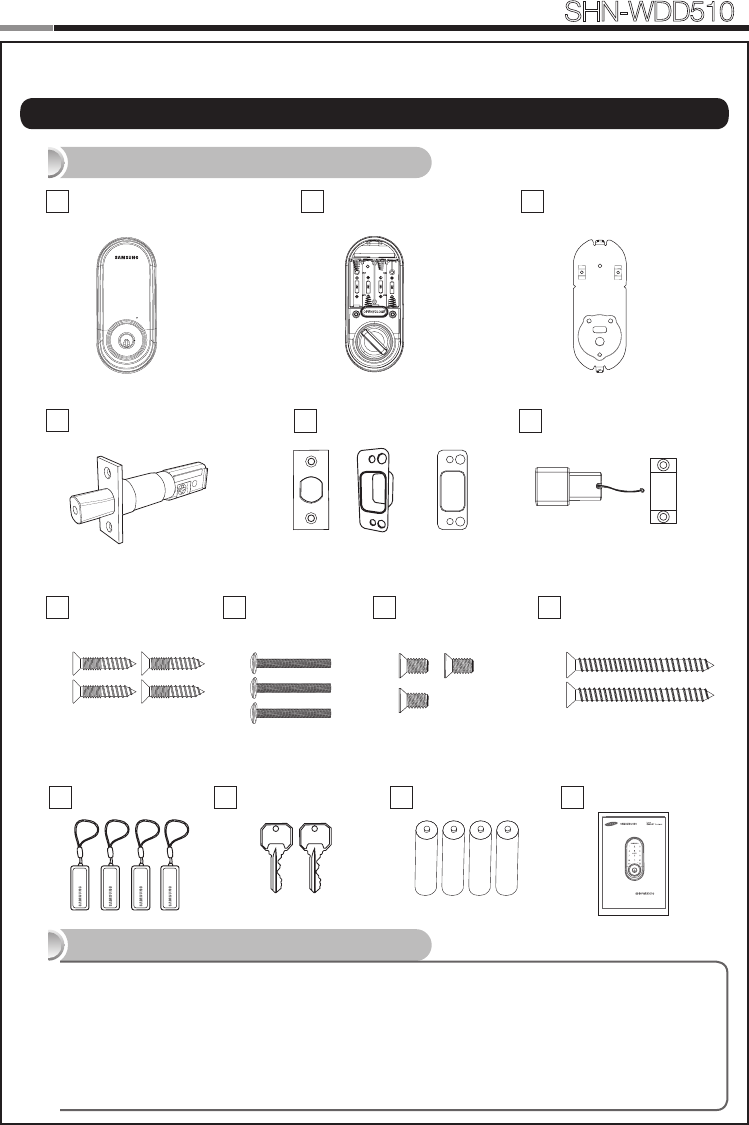
| Components & Tools
Door Preparation
● 2-1/8˝(54mm) hole saw: Main Hole
● 1˝(25mm) hole saw: Dead bolt hole
● 1/8˝(2.5mm) drill bit: Dead bolt screw hole
● Chisel and hammer
● Drill
Lock Installation
● #2 Phillips screwdriver
● Pincers: Cut the tailpiece
Components and Drawing
Tools
INSTALLATION
Exterior Unit
A
Door Side Doorframe Side
Interior Unit
BInterior Mounting
Plate
C
Adjustable Deadbolt
DStrike Parts
EMagnetic Sensor
F
Screw for Strike and
Dead bolt
G1 Screw for
mounting plate
G2 Screw for Interior
unit
G3
Batteries
J
Mechanical Keys
IUser Manual
K
Please review all included documentation and use the product as i ntended. Safety precautions must be
followed to avoid personal injury or property damage.
Samsung Smart Door Lock
User Guide SHN-WDD510
Spec: FH+T4x19 Spec: PH+M4x40 Spec: FH+M4x8
RF Tag
H
REG SET
Strike Dust Box
Screw for Reinforcement
plate
Spec: FH+T5x76
G4
Reinforcement
plate
4
Smart
Door Lock SHN-WDD510
5
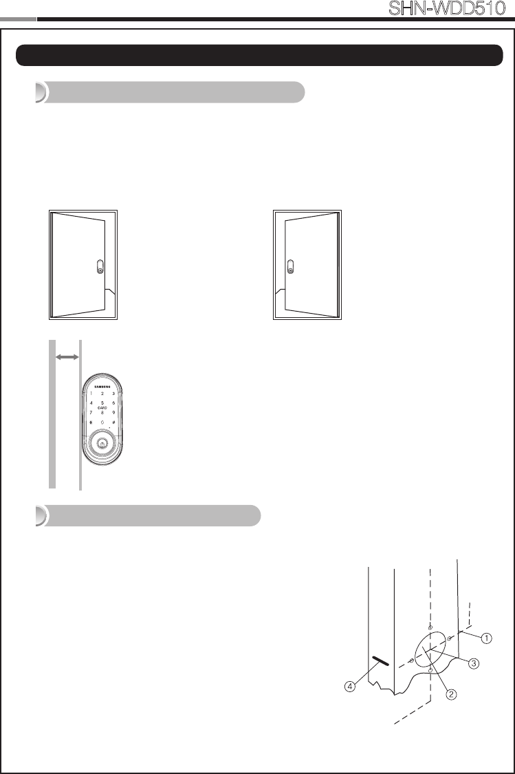
| Door Preparation
Step 1. Check the Door Status
1) This lock supports door thickness of 1-3/8” to 2-5/32” (35 to 55mm).
2) Using the provided lock template, ensure that there are no obstructions that would prevent
installing the lock properly.
3) Take note of which orientation the deadbolt will need to be installed, left hand or right
hand.
Check the location and direction of the deadbolt, attach the drilling template (page 27) on
the side of the door, and mark on it with a pen.
1) Align the horizontal line across the door.
2) Align the vertical line over the door.
3) Mark the centers of the holes with the drilling template.
4) Mark the centerline of the deadbolt by aligning it with the
vertical line.
Right-handed Door
When viewed from the Outside,
the hinge is on the right.
Left-handed Door
When viewed from the
Outside, the hinge is on the
left.
Step 2. Mark on the Door
Please, be aware of that there has be more than
50mm gap between the door frame.
Min. 50mm
4
5
Smart
Door Lock SHN-WDD510
1) Drill a 2-1/8˝ (54 mm) diameter hole through the door, as indicated on
the template, using a hole saw.
2) Drill a 1˝ (25 mm) mortise hole using a hole saw.
3) Drill strike plate holes using a drill bit (1/8˝, 2.5 mm).
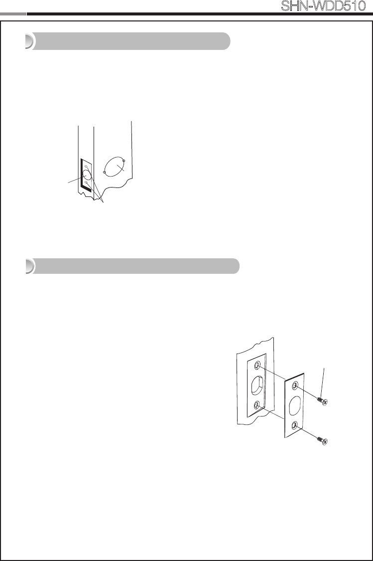
1) Using the template, locate the center horizontal
line for the deadbolt hole, which lines up with the
center of the 2-1/8˝ hole, and draw a horizontal line
on the door frame to mark where you will make the
deadbolt mortise hole.
2) Measure half the thickness of the door. Now,
measure that distance from where the door stops
at the frame when the door is closed toward the
door jamb and mark a straight, vertical line the
length of the door strike plate. Draw a horizontal
line from the mark you made in Step 1 toward the
vertical line. Where both lines cross, make a 1˝ (25
mm) diameter hole, 1/2˝ (13 mm) in depth.
3) Align the holes of the strike plate with the vertical
line. Trace the outline of the strike plate and
mortise with a 1/16˝ (1.6 mm) indentation. Attach
the strike plate with the 2 screws provided.
Step 3. Drilling
Step 4. Strike Plate Installation
FH+ T4 x 19
① 54mm
② 25mm
③ 2.5mm
6
Smart
Door Lock SHN-WDD510
7
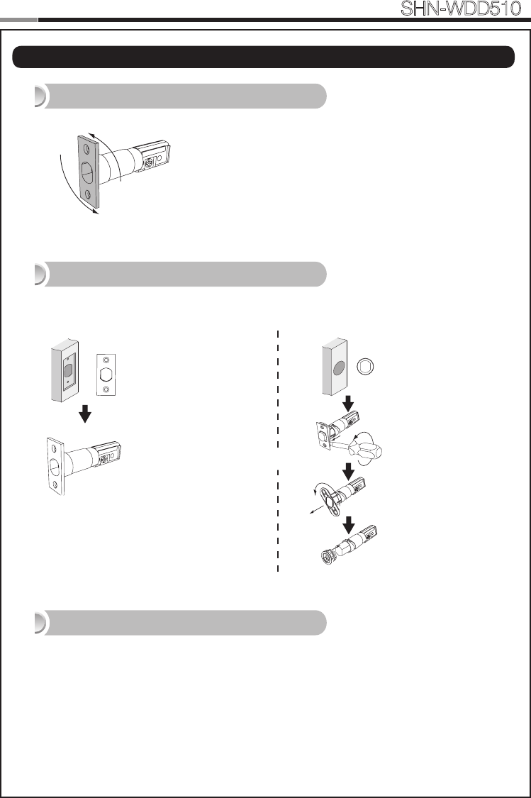
| Preparing the parts
1. Adjusting the length of the dead bolt
180°
Turn the body of the dead bolt to adjust the length
of the dead bolt.
It can be 60mm (2-3/8”) or 70mm (2-3/4”)
OR
Rectangle Strike hole
: No need to change.
2. Changing the faceplate of the dead bolt
Change the faceplate of the dead bolt following the size of a strike hole.
Round Strike hole
1. Remove the strike
faceplate with a
screw driver.
2. Turn the inner
faceplate to take
out it.
3. Insert the round
faceplate.
OR
OR
3. Adjusting the length of the tailpiece
How to cut
1. Press the V-cut line with pincers to make more cut line.
2. Hold the end of the tailpiece with pincers.(Cut the tailpiece 5mm longer than the door thickness.)
3. Bend it up and down until it is separated.
- For more information, refer to page 31.
6
7
Smart
Door Lock SHN-WDD510
D
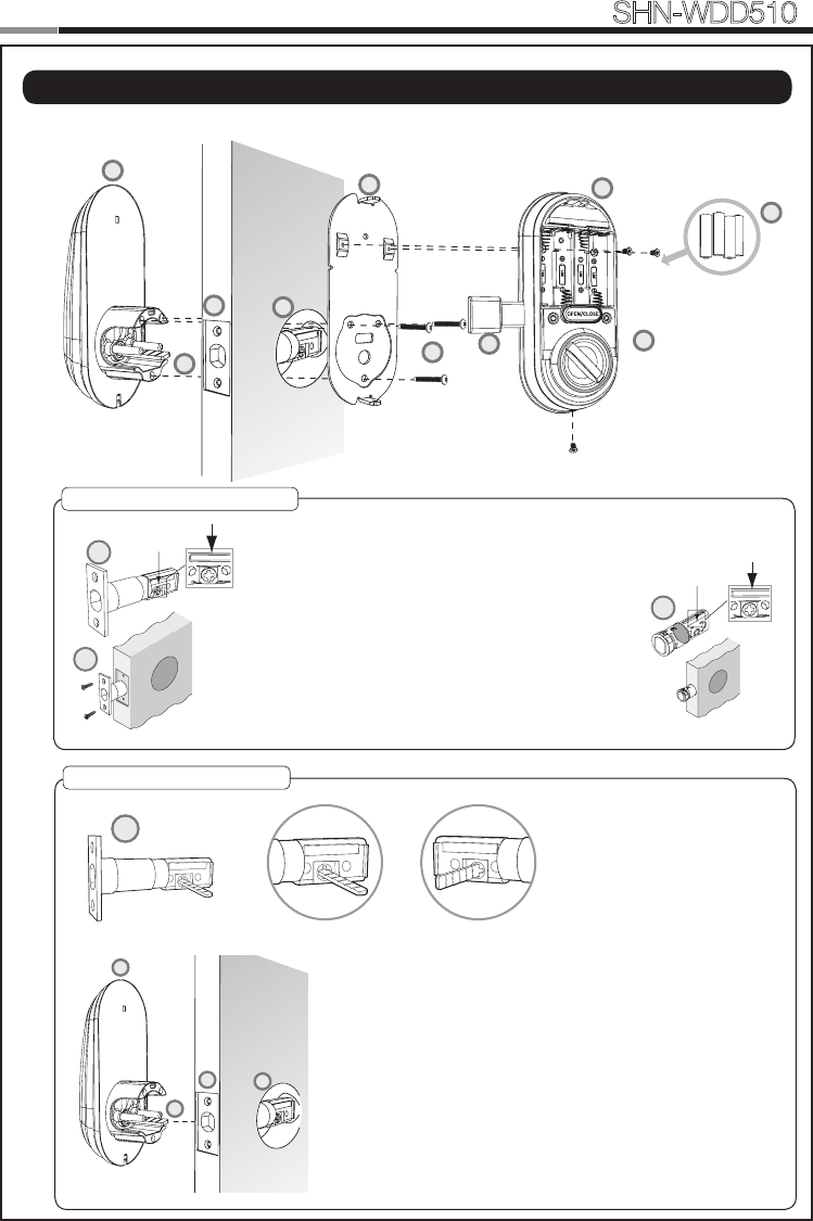
| Installing lock
Outside Inside
1. Installing the Dead Bolt(E)
1. Before installation
1) Check the faceplate type of your door.
2) Make sure the deabolt directon as shown before
inserting it into a door side.
2. Insert the deadbolt from the side of the door.
3. Fix the deadbolt using two FH+T4X19 screws.
* If there is round strike hole, change the faceplate, and
insert the deadbolt following right side drawing.
2. Installing the Exterior Unit
1. Ensure the Exterior Unit is aligned with the center hole of
the deadbolt and Cut the tailpiece 5mm longer than the
door thickness(refer to the page 31).
2. Attach the exterior unit.
CAUTION: The dead bolt must be in a retracted position.
In case of right-handed door, insert the tailpiece vertically.
In case of left-handed door, insert the tailpiece horizontally.
E
G1
D
Left-handed Right-handed
D
A
H
E
C
F
B
J
D
A
G2
G3
E
H
REG
SET
8
Smart
Door Lock SHN-WDD510
9
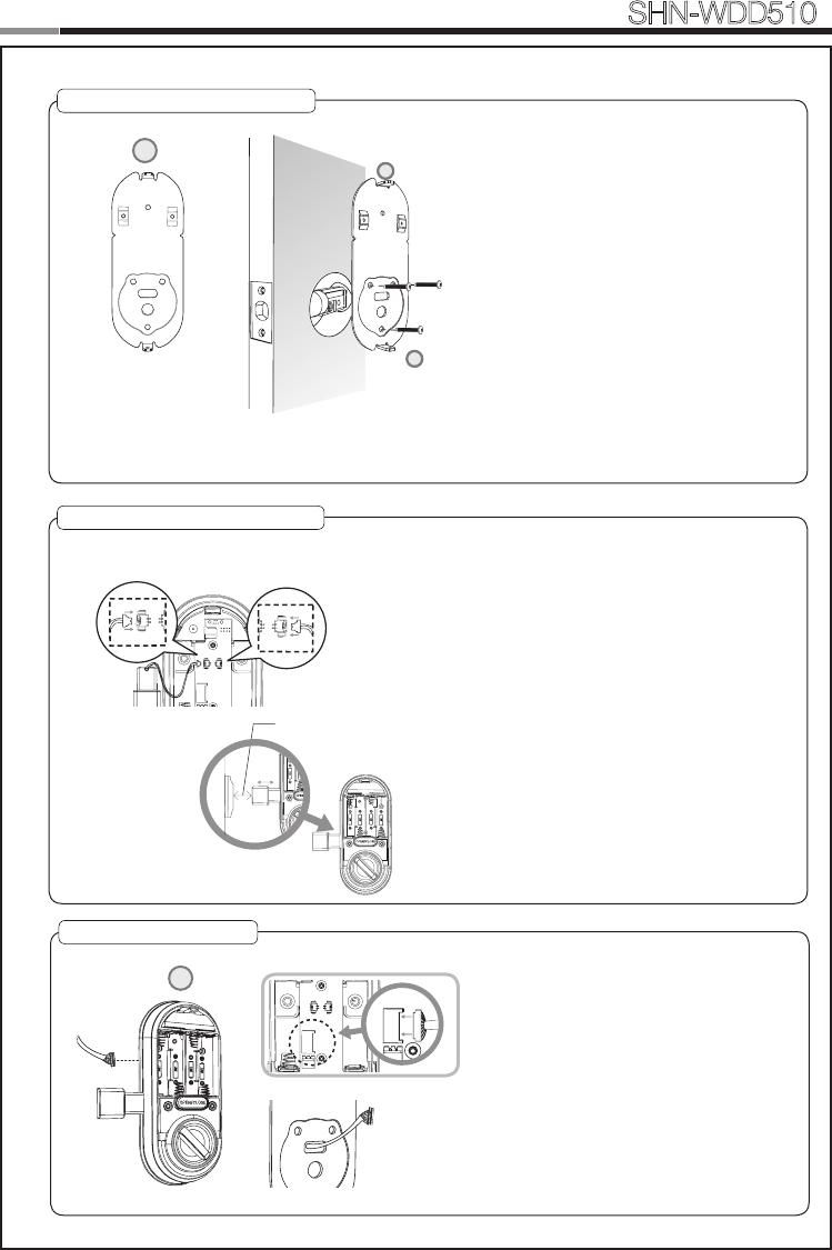
4. Installing the Magnetic Sensor
Install the door side magnetic sensor.
It should be installed in right way of the door.
CAUTION: The gap of the magnet sensors
between the door side and the door-frame should
be within 3/4”(20mm). If the gap is to wide, pull out
the door side magnetic sensor to adjust the gap
enough to detect.
5. Connecting the cable
B
REG SET
3. Installing the Mounting Plate
1. Detach the Interior Mounting Plate from
the interior unit.
2. Fasten the interior mounting plate with
three TH+M5x40 (G2) 90% of the way.
3. Align the Exterior Unit with the Interior
Mounting Plate and then tighten the
screws.
4. Cover the rubber pad on the Interior
Mounting plate.
CAUTION: Do not over-tighten, and check
the movement of dead bolt by the mechani-
cal key.
C
C
G2
3/4˝(20mm)
SET
REG
REG
Left-handedRight-handed
1. Connect the cable from the exterior unit
to the interior unit.
2. After connecting the cable, push the
cable into the hole of the door.
8
9
Smart
Door Lock SHN-WDD510
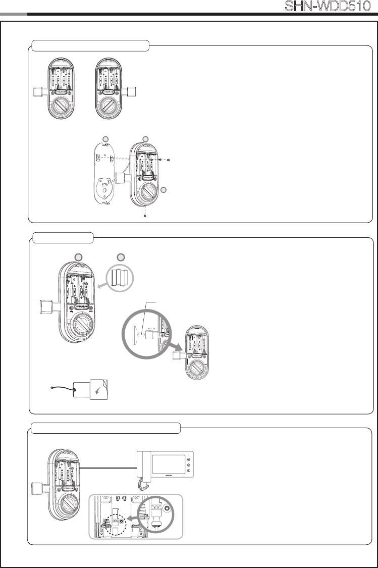
6. Fix Screw for the Interior Unit
1. Before installing the interior unit, check the
direction of the thumb turn while the dead bolt is
in the OPEN POSITION.
2. Open the battery cover.
3. Align the Interior Unit on to the Interior Mounting
Plate, and attach it with 4 screws.
CAUTION: Check the movement of the dead bolt
by the thumb turn.
7. Final Check
1. Install 4 batteries. A Melody will sound
when all 4 batteries are installed
correctly.
2. Close the door to detect the magnetic
sensor. You can hear the beep sound
when the magnetic sensor detects.
After that, press [OPEN/CLOSE]
button to check whether the dead bolt
works properly.
3. Stick the magnetic sensor with
attention on the distance.
CAUTION: The gap between the door
side and the door-frame magnetic sensors
should be close enough to be detected.
OPTION : Connection for Video Intercom
Connect the cable of video intercom to the
Interior Unit.
SHN-WDD510 receives 1 second of dry
contact signal to open the door remotely.
It is normally compatible with SHT-3006 and
other Samsung Video Intercom systems.
Dry Contact
Signal
3/4˝(20mm)
1
2
3
C
REG SET
B
G3
SETREG SETREG
Left-handed Right-handed
SETREG SETREG
B J
REG SET
SET
REG
REG
10
Smart
Door Lock SHN-WDD510
11
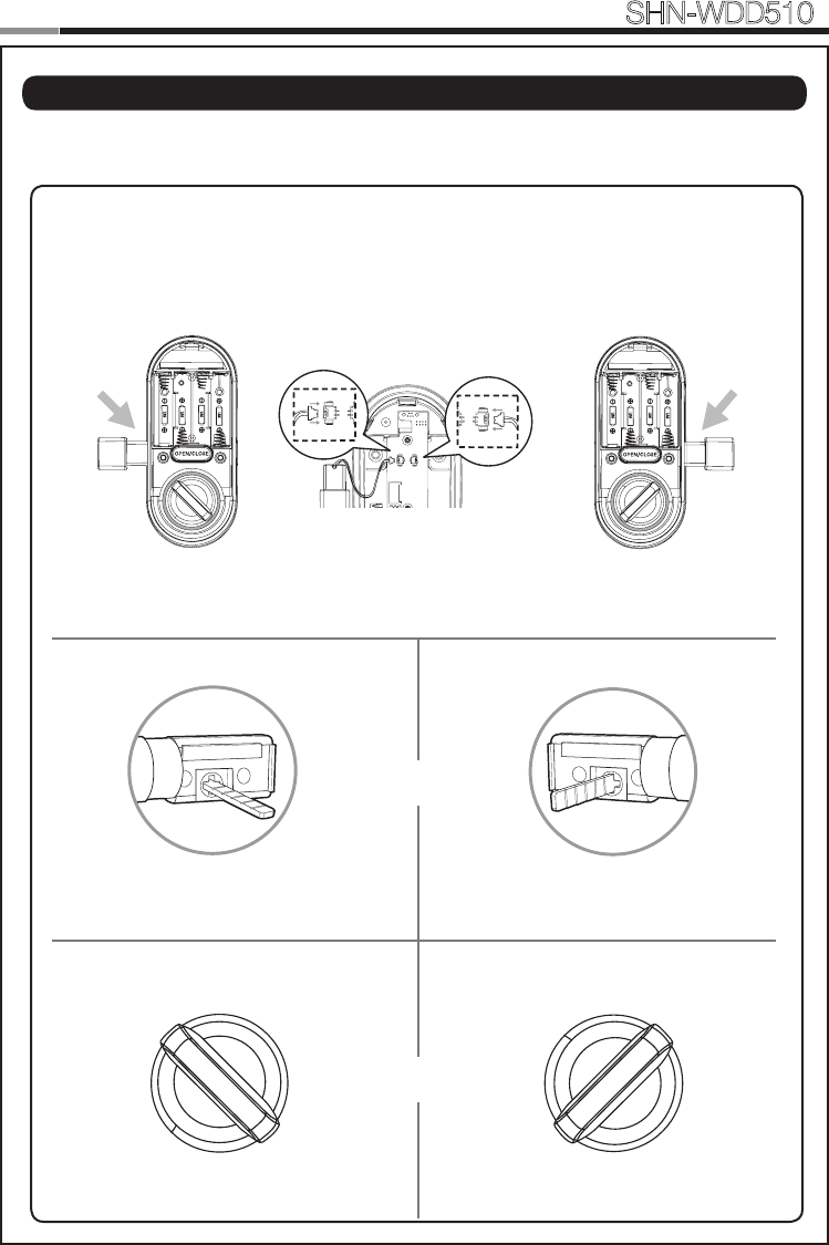
| Setting of Right-Handed / Left Handed
*All status should be checked while the dead bolt is in OPEN POSITION.
Right-handed
Left-handed
SETREG SETREG
SETREG SETREG
Tailpiece
Thumb turn
Left-handedRight-handed
10
11
Smart
Door Lock SHN-WDD510
PROGRAMMING
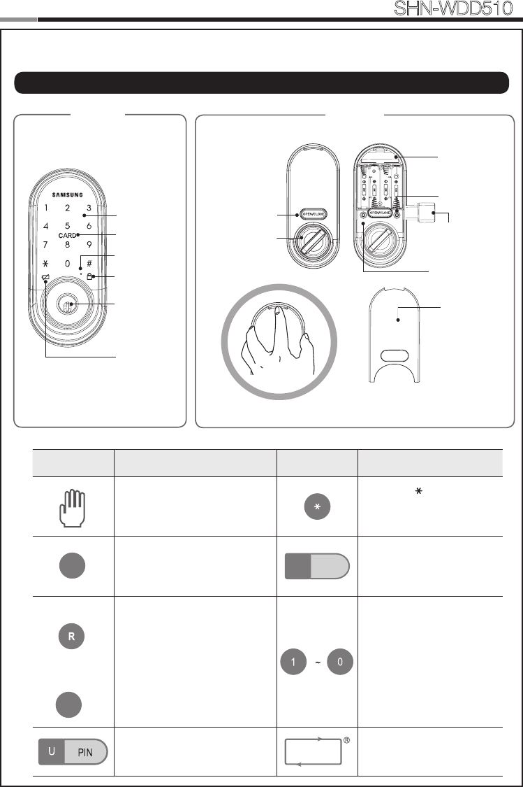
REG SET
Touchscreen
Emergency
Key Hole
Exterior Interior
Battery Cover
Open/Close Button
Thumbturn Lever
Restart Button
Card Reader
Magnetic Sensor
[REG] Button
[SET] Button
Network Module
Slot
Privacy Mode
Indicator
Low Battery
Indicator
Symbols Description Symbols Description
Touch the [Touchscreen].
Press the [ ] button. It is
used to complete number
entry.
SET: Used for setting the
Additional Functions.
Mstr PIN
Enter the Master PIN Code
(4~10 digits).
Factory Default: 1234
REG: Open the battery cover
of the Interior Unit and press
the [REG] button. It is used
to begin or exit the Program
mode.
REG3: Press the [REG] button for
3 seconds.
Press the Number buttons.
Enter the User PIN Code (4~10
digits).
Repeat the process inside
the rectangle.
| Programming Features
S
3
R
12
Smart
Door Lock SHN-WDD510
13
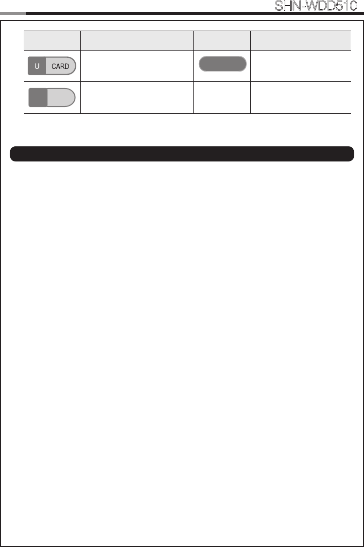
Symbols Description Symbols Description
Touch the Card reader with the
User Card.
Press the [OPEN/CLOSE]
button.
U No
Enter the User Number. Can be
set from 1 to 100.
OPEN / CLOSE
Indicator Lamp : Indicates the operational status when the Card is being read or the lock is in
operation.
Intrusion Detection Function : When the Interior Unit is forcibly detached while the door is
locked, it is detected by the magnetic sensor and an alarm is sounded. (The function is not activated
when the magnet is not used.)The Intrusion Detection function is a basic function and cannot be
enabled or disabled.
Locking Mode (Auto/Manual) : You can enable or disable the function for locking the door
automatically when it is closed. The factory default is ‘Auto mode’.
- Auto: The door is locked automatically 2 seconds after it is closed. However, it does not function if
the magnet is not used or the batteries are completely discharged.
- Manual: When the door does not lock automatically when it is closed, touch the [Touchscreen] or
the [OPEN/CLOSE] button on the Interior Unit will lock the door.
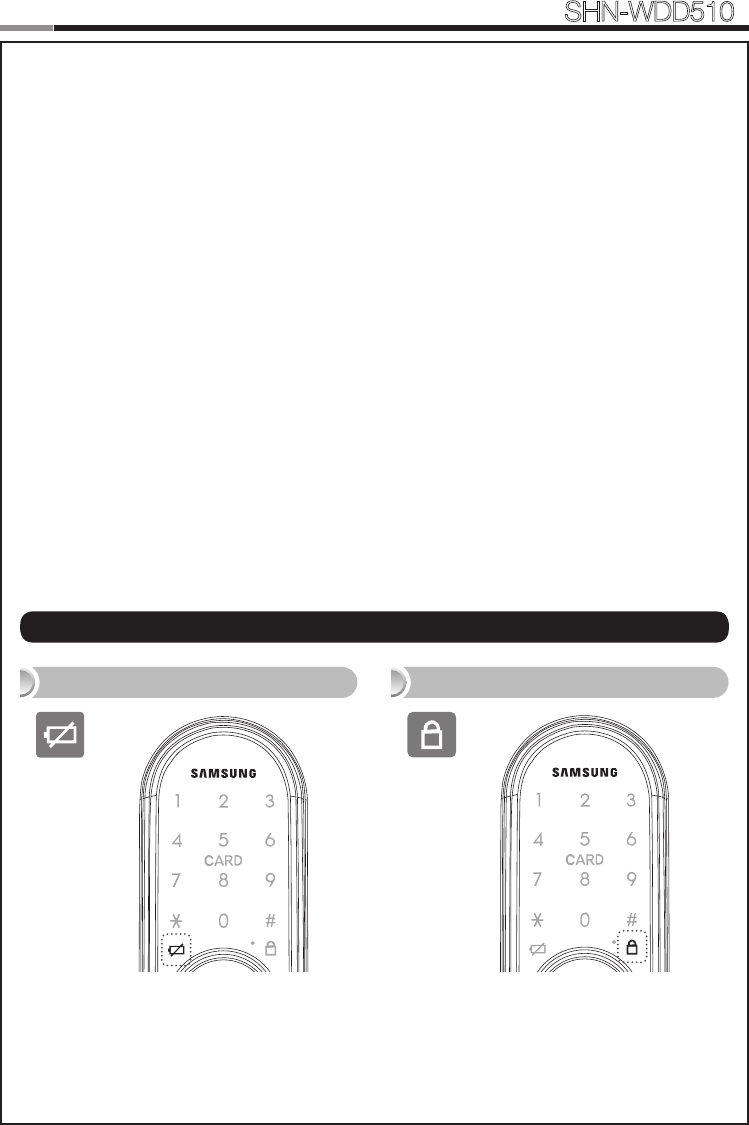
Low Voltage Indicator : Refers to the state when the operating voltage of the lock is lower than
the standard voltage, and activates the Low Voltage Alarm (“Please change the batteries”) to indi-
cate that the batteries need to be replaced. Use the Emergency Key when the batteries are com-
pletely discharged. In case of the low voltage, the low-votage LED ickers when using doorlock.
Magnetic Sensor : Detects the opening and closing of the door.
Thumbturn Lever : When the batteries are completely discharged, this device is used to me-
chanically lock or unlock the door from inside.
Master PIN Code : You can enter only one Master PIN (4-10 digits) Code. You can register the
User PIN Codes/Cards after authenticating with the Master PIN (4-10 digits) Code. You can open
the door with the Master PIN Code, and the factory default is ‘1234’.
OPEN/CLOSE Button : A one-touch button to open the locked door. (It is also used to lock the
door from inside in the Manual locking mode.)
Privacy Mode : Privacy Mode prevents the lock from being unlocked from the outside. You can
enable it by using the [OPEN/CLOSE] button. The Privacy Mode LED on, when Privacy Mode func-
tion is activated.
Random Security Function : This mode prevents the disclosure of the PIN Code by entering
the PIN Code after authenticating 2 arbitrarily selected numbers. When the buttons for 2 arbitrarily
selected numbers are illuminated, pressing the 2 illuminated buttons illuminates the whole touch-
screen. You can enable or disable the Random Security function. This function is enabled by de-
fault.
Registration Button : This button is used to change Master PIN Code/User PIN Codes/User
| Denitions
12
13
Smart
Door Lock SHN-WDD510
Status Indicators
Privacy Mode Indicator
Low Battery Indicator
Cards or the lock settings. It is found below the battery cover of the Interior Unit. The length of time
the [REG] button is pressed varies depending on the function.
Resetting : Deletes all registered information and restores the factory default. After resetting,
change the Master PIN Code for security.
Restart Button : This button resets the lock when the lock stops functioning. Registered informa-
tion is not deleted.
Set Button : Used for setting the Additional Functions. It is found below the battery cover of the
Interior Unit.
Sound Setting : The volume during the input of numbers and opening or locking of the door can
be set from Level 0 ~ Level 2. The sound is muted at Level 0 and is at maximum volume at Level 2.
The registration mode operates at Level 1 regardless of the sound setting.
User Card : You can register up to 100 User Cards including the User PIN Codes. You can open
the door with a User Card.
User Number : It is the same number as the registered user’s address and can be set from 1 to
100. The User Number should be managed with caution as it is used to register or delete User PIN
Codes/Cards.
User PIN Code : You can register up to 100 User PIN Codes (4-10 digits) including the User
Cards. You can open the door with a User PIN Code.
Network Module : After registering Network Module, Smart doorlock is able to be remotely-con-
trolled via Gateway(optional).
14
Smart
Door Lock SHN-WDD510
15
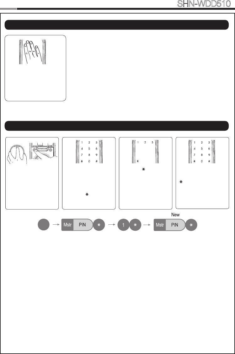
Touch the [Touchscreen].
Touch lock with back of
hand or ngers to acti-
vate.
Open the battery cover
of the Interior Unit and
press the [REG] button
briey.
When the touchscreen
is illuminated, enter the
current Master PIN Code
(default is ‘1234’) and
press the [ ] button.
Press the [ ] button after
pressing the [1] button.
Enter the new Master
PIN Code and press the
[ ] button.
Note: Master PIN Code
must be 4~10 digits.
REG SET
R
No
1~100
No
1~100
No
1~100
No
1~100
R
2
2
2
3
3
3
No
1~100
No
1~100
No
1~100
No
1~100
R
2
2
2
3
3
3
Lock Activation
Changing the Master PIN Code
14
15
Smart
Door Lock SHN-WDD510
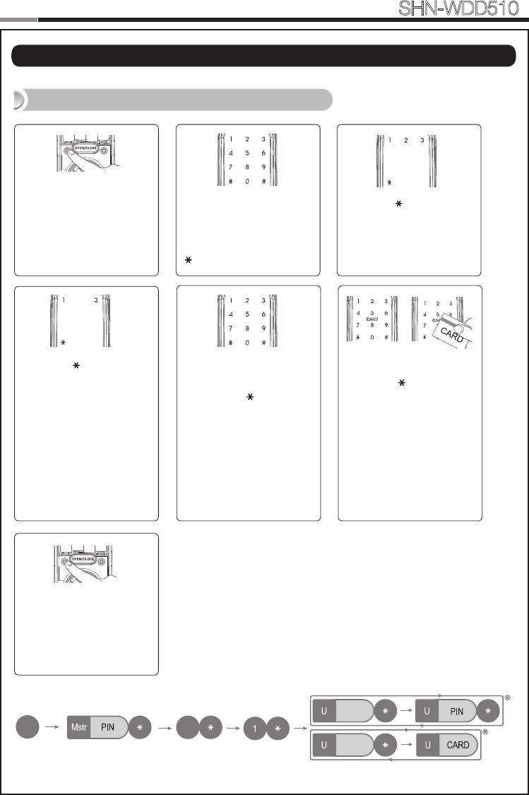
Registering a User PIN Code/ Card
Open the battery cover of
the Interior Unit and press
the [REG] button briey.
When the touchscreen is il-
luminated, enter the current
Master PIN Code (default
is ‘1234’) and press the
[ ] button.
Press the [ ] button after
pressing the [2] button.
Enter a User Number(1~ 100)
to register the User PIN Code
and press the
[ ]
button.
*Choose a User Number that
has not already been used.
**
If don’t enter a User Number
and press (0) when registering,
the User Number is sequential-
ly assigned on the emprty User
Number from 1 to 100.
Enter a new User PIN Code
and press [ ] button.
Touch the Card reader with
the Card to register.
Note: User PIN Code must
be 4~10 digits.
Enter another User Num-
ber or press the [REG] but-
ton to quit.
REG SET
REG SET
Press the [ ] button after
pressing the [1] button.
No
1~100
No
1~100
No
1~100
No
1~100
R
2
2
2
3
3
3
No
1~100
No
1~100
No
1~100
No
1~100
R
2
2
2
3
3
3
|
Managing User PIN Code/ Card
16
Smart
Door Lock SHN-WDD510
17
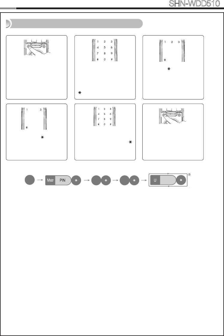
Deleting User PIN Code / User Card
Enter the User Number (1
to 100) and press the [ ]
button.
Open the battery cover of
the Interior Unit and press
the [REG] button briey.
When the touchscreen is il-
luminated, enter the current
Master PIN Code (default
is ‘1234’) and press the
[ ] button.
Press the [ ] button after
pressing the [2] button.
REG SET
Press the [ ] button
after pressing the [3] but-
ton.
No
1~100
No
1~100
No
1~100
No
1~100
R
2
2
2
3
3
3
No
1~100
No
1~100
No
1~100
No
1~100
R
2
2
2
3
3
3
No
1~100
No
1~100
No
1~100
No
1~100
R
2
2
2
3
3
3
Enter another User Num-
ber or press the [REG] but-
ton to quit.
REG SET
16
17
Smart
Door Lock SHN-WDD510
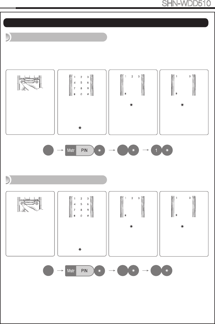
Open the battery cov-
er of the Interior Unit
and press the [REG]
button briey.
When the touchscreen
is illuminated, enter the
current Master PIN Code
(default is ‘1234’) and
press the [ ] button.
Press the [ ] button after
pressing the [3] button.
REG SET
Note: After registering Network Module, Smart doorlock is able to be remotely-
controlled via Gateway(optional).
|
Managing Network Module
Registering Network Module
Deleting Network Module
Press the [ ] button after
pressing the [1] button.
R
No
1~100
No
1~100
No
1~100
No
1~100
R
2
2
2
3
3
3
No
1~100
No
1~100
No
1~100
No
1~100
R
2
2
2
3
3
3
No
1~100
No
1~100
No
1~100
No
1~100
R
2
2
2
3
3
3
Open the battery cov-
er of the Interior Unit
and press the [REG]
button briey.
When the touchscreen
is illuminated, enter the
current Master PIN Code
(default is ‘1234’) and
press the [ ] button.
Press the [ ] button after
pressing the [3] button.
REG SET
Press the [ ] button after
pressing the [3] button.
R
No
1~100
No
1~100
No
1~100
No
1~100
R
2
2
2
3
3
3
No
1~100
No
1~100
No
1~100
No
1~100
R
2
2
2
3
3
3
No
1~100
No
1~100
No
1~100
No
1~100
R
2
2
2
3
3
3
18
Smart
Door Lock SHN-WDD510
19
Touch the Card reader
with an Access Card
|
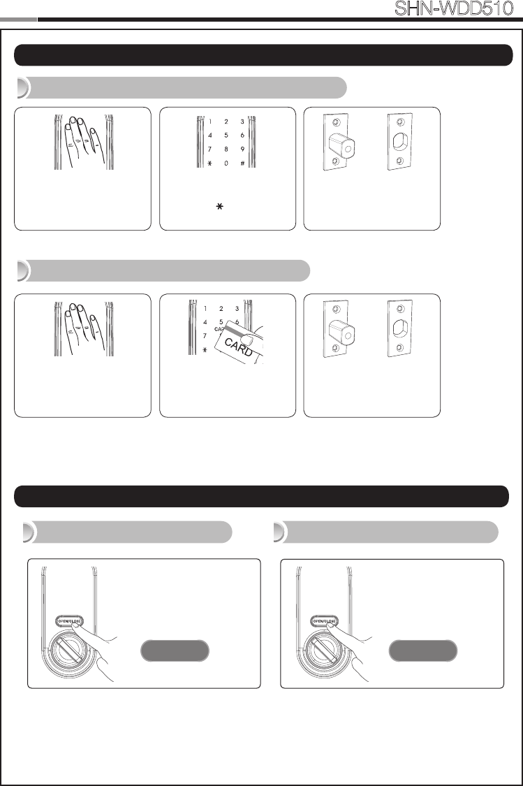
Basic Lock Operation Overview
Opening the Door with a PIN Code
Opening the Door with a Card
Enter the PIN Code and
press the [ ] button.
Press the [OPEN/
CLOSE] button for 3
seconds while the door
is locked.
Press the [OPEN/
CLOSE] button or turn
the Thumbturn lever.
Activating Privacy Mode Deactivating Privacy Mode
| Privacy Mode Functions
OPEN / CLOSEOPEN / CLOSE
3
Touch the [Touchscreen].
→
The door opens within one
second.
Touch the [Touchscreen].
→
The door opens within one
second.
18
19
Smart
Door Lock SHN-WDD510
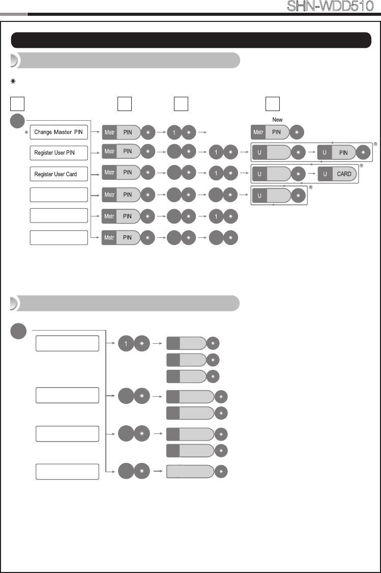
| Programming Through Menu Mode Using Master Code
Note: Maximum number of user registration is 100. (User PIN Codes, User Cards, Key Fobs)
Program Operation in Master Mode
32 4
: Master Program Mode Only
Delete User PIN / Card
No
1~100
No
1~100
No
1~100
Registering Network Module
Deleting Network Module
R
2
2
2 3
3
33
1
Silent
1
Low ※ Default
※ Default
※ Default
2
High
3
Auto lock
1
Manual lock
3
Enable
1
Disable
3
Volume Setting
Locking Mode
Random Security Mode
Local Time Setting
S
2
3
4YYMMDDHHMM
Addtional Function Mode
20
Smart
Door Lock SHN-WDD510
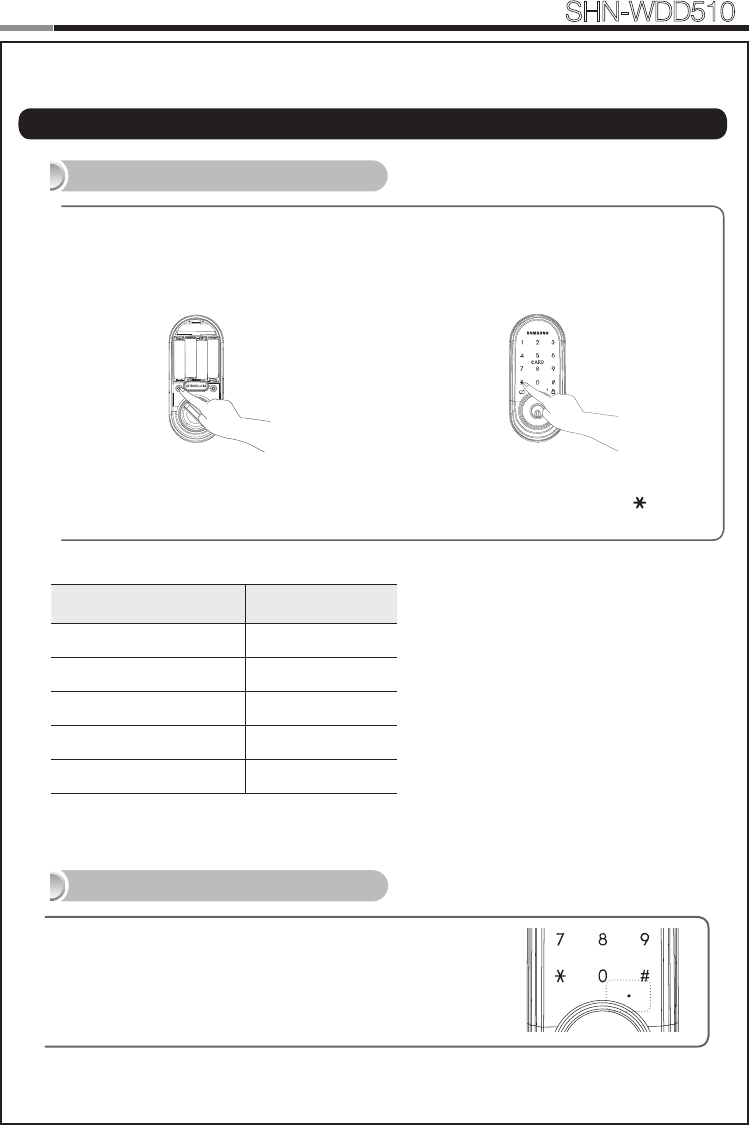
| Miscellaneous Information
Reset to Factory Default
Restart Function
20
Note: Restarting does not delete registered information.
If there is no response after touching the [Touchscreen],
use a pin to press the [Restart] button on the left of the
external power contact of the Exterior Unit.
REG SET
Press the [REG] button for 3 seconds. Enter the current Master PIN Code
or “4560852580” and press the [ ] button.
Resetting the lock will delete all registered information.
Note: All registered Master and user data will be deleted, and the lock will be reset
to default settings.
Function Factory Default
Master PIN Code 1234
Volume Low
User PIN Code/Card None
Locking Mode Auto
Random Security Disabled
MISCELLANEOUS
20
Smart
Door Lock SHN-WDD510
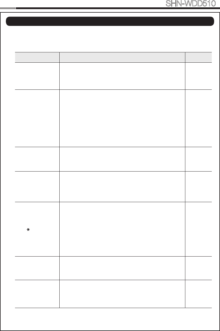
When the lock doesn’t function correctly, please check the items below.
If you can’t resolve the problem, please contact the nearest service center.
Problem Resolution Reference
There is no power.
● Check if the batteries are inserted in the correct polarity.
● Check that the batteries have a full charge.
● Check that the Exterior Unit cable has not come loose.
-
I can’t change the
Master PIN Code.
● There was a delay while changing the PIN Code. The
touchscreen must be illuminated when changing the PIN
Code. Also, after entering the rst digit, the next digit must
be entered within 20 seconds.
● Replace the batteries if they are discharged.
● Refer to the ‘Changing the Master PIN Code’ section in
the user manual and try again. Ensure that the Master
PIN Code is 4~10 digits long.
Page 14
I can’t register the
User PIN Code.
● The User Number has already been used. Delete the de-
sired User Number and re-register.
● Ensure that the User PIN Code is 4~10 digits long.
Page 15
I can’t register the
User Card.
● The User Number has already been used. Delete the de-
sired User Number and re-register.
● Ensure that the card is touched to the card reader within
20 seconds of entering the User Number.
Page 15
I entered the PIN
Code and pressed
the [ ] button,
but the door won’t
open.
● Check that the registered PIN Code was entered cor-
rectly.
● If the touchscreen illumination turns off while entering the
PIN Code, the button input was not registered. Touch the
[Touchscreen] to illuminate the touchscreen and enter
the PIN Code again from the beginning. (The touchscreen
illumination is turned off automatically if there is no input
within 5 seconds.)
Page 18
I can’t unlock the
door with my Card.
● The Card is either unregistered or unrecognized.
● The Card must touch the Card reader correctly. Page 18
My PIN Code or
Card is authenti-
cated, but the door
won’t open.
The lock may be malfunctioning. Please contact service
center. -
| Troubleshooting
21
22
Smart
Door Lock SHN-WDD510
23
The door won’t
lock automatically
when I close it.
● Check if Auto Locking is set. When Manual Locking is set,
touching the [Touchscreen] locks the door.
● If the door doesn’t lock automatically when Auto Locking
is set, then the lock has been installed incorrectly.
● The Auto Locking function is not activated when the bat-
teries are completely discharged. Check if the batteries
are discharged.
Page 19
There is no
response when I
touch the [Touch-
screen].
● Use a pin to press the hole on the front of the Exterior
unit.
● If doing the above does nothing, contact the service
center.
Page 20
22
23
Smart
Door Lock SHN-WDD510
User No. PIN CODE/CARD User Name User No. PIN CODE/CARD User Name
| User Registration Table
24
Smart
Door Lock SHN-WDD510
25
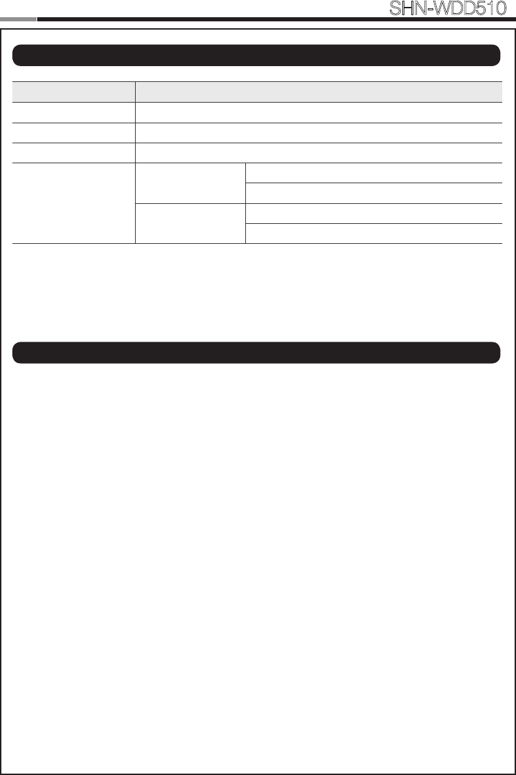
Item Specications
Voltage 4 AA Alkaline 1.5V Batteries (LR6) (6V)
Operation Method Electronic Control Method (PIN Code entry or Card reading)
Weight 1.8Kg (including both inside and Exterior Unit)
Product Dimensions
Exterior Unit 69.8 mm (W) x 159.8 mm (H) x 35.2 mm (D)
2-3/4˝ (W) x 6-9/32˝ (H) x 1-3/8˝ (D)
Interior Unit 70.4 mm (W) x 163.8 mm (H) x 39 mm (D)
2-25/32˝ (W) x 6-7/16˝ (H) x 1-17/32˝ (D)
The content of this manual is subject to change without prior notice to the user in order to enhance the
performance of the product.
| Product Specications
| FCC NOTICE
NOTE : This equipment has been tested and found to comply with the limits for a Class B digital de-
vice, pursuant to part 15 of the FCC Rules. These limits are designed to provide reasonable protection
against harmful interference in a residential installation.
This equipment generates, uses and can radiate radio frequency energy and, if not installed and used
in accordance with the instructions, may cause harmful interference to radio communications. However,
there is no guarantee that interference will not occur in a particular installation. If this equipment does
cause harmful interference to radio or television reception, which can be determined by turning the
equipment off and on, the user is encouraged to try to correct the interference by one or more of the
following measures:
- Reorient or relocate the receiving antenna.
- Increase the separation between the equipment and receiver.
- Connect the equipment into an outlet on a circuit different from that to which the receiver is con-
nected.
- Consult the dealer or an experienced radio/TV technician for help.
CAUTION :
- Changes or modications not expressly approved by the manufacturer responsible for compliance
could void the user’s authority to operate the equipment.
- This equipment complies with the FCC RF radiation exposure limits set forth for an uncontrolled
environment.
This equipment should be installed and operated with a minimum distance of 20cm between the
radiator and any part of your body.
24
25
Smart
Door Lock SHN-WDD510
LIMITED PRODUCT WARRANTY
Installation of the product is considered acceptance of warranty conditions
SAMSUNG SDS CO., LTD (SAMSUNG SDS) warrants its products to be free from manufactur-
ing defects in materials and workmanship for 12 months from the date of purchase. SAMSUNG
SDS will, within said period, at its option, repair or replace any product failing to operate correctly
without charge to the original purchaser or user.
This warranty shall not apply to any equipment, or any part thereof, which has been repaired by
others, improperly installed, improperly used, abused, altered, damaged, subjected to acts of
God, or on which any serial numbers have been altered, defaced or removed. SAMSUNG SDS
does not warrant the performance or sale conditions of the seller/installer.
There are no warranties, express or implied, which extend beyond the description on the face
hereof. There is no express or implied warranty of merchantability of a warranty of tness for a
particular purpose. Additionally, this warranty is in lieu of all other obligations or liabilities on the
part of SAMSUNG SDS.
Any action for breach of warranty, including but not limited to any implied warranty of merchant-
ability, must be brought within the six months following the end of the warranty period. In no case
shall SAMSUNG SDS be liable to anyone for any consequential or incidental damages for breach
or this or any other warranty, express or implied, even if the loss or damage is caused by the
seller’s own negligence or fault.
SAMSUNG SDS shall have no obligation under this warranty, or otherwise, if the product has
been repaired by others, improperly installed, improperly used, abused, altered, damaged, sub-
jected to accident, nuisance, ood, re or acts of God, or on which any serial numbers have been
altered, defaced or removed. SAMSUNG SDS and its distributor will not be responsible for any
dismantling, reassembly or reinstallation charges. This warranty contains the entire warranty. It is
the sole warranty and any prior agreements or representations, whether oral or written, are either
merged herein or are expressly cancelled. SAMSUNG SDS neither assumes, nor authorizes
any other person purporting to act on its behalf to modify, to change, or to assume for it, any
other warranty or liability concerning its products. In no event shall SAMSUNG SDS be liable for
an amount in excess of SAMSUNG SDS’s original selling price of the product, for any loss or
damage, whether direct, indirect, incidental, consequential, or otherwise arising out of any failure
of the product. Seller’s warranty, as hereinabove set forth, shall not be enlarged, diminished or
affected by and no obligation or liability shall arise or grow out of Seller’s rendering of technical
advice or service in connection with Buyer’s order of the goods furnished hereunder.
SAMSUNG SDS recommends that the entire system be completely tested weekly.
Warning: Despite frequent testing, and due to, but not limited to, any or all of the following;
criminal tampering, electrical or communications disruption, it is possible for the system to fail
to perform as expected. SAMSUNG SDS does not represent that the product/system may not
be compromised or circumvented; or that the product or system will prevent any personal injury
or property loss by burglary, robbery, re or otherwise; nor that the product or system will in all
cases provide adequate warning or protection. A properly installed and maintained alarm may
only reduce risk of burglary, robbery, re or otherwise but it is not insurance or a guarantee that
these events will not occur.
26
Smart
Door Lock SHN-WDD510
27
Consequently, seller shall have no liability for any personal injury, property damage, or other loss
based on a claim the product failed to give warning.
Therefore, the installer should in turn advise the consumer to take any and all precautions for his
or her safety including, but not limited to, eeing the premises and calling police or re depart-
ment, in order to mitigate the possibilities of harm and/or damage. SAMSUNG SDS is not an
insurer of either the property or safety of the user’s family or employees, and limits its liability for
any loss or damage including incidental or consequential damages to SAMSUNG SDS’s original
selling price of the product regardless of the cause of such loss or damage.
Some states do not allow limitations on how long an implied warranty lasts or do not allow the
exclusion or limitation of incidental or consequential damages, or differentiate in their treatment
of limitations of liability for ordinary or gross negligence, so the above limitations or exclusions
may not apply to you. This Warranty gives you specic legal rights and you may also have other
rights which vary from state to state.
In case of the product defect, contact our authorized Customer Service Center. In order to exer-
cise the warranty, you must contact our authorized Customer Service Center and obtain a proper
RMA # - the product must be returned to our authorized Customer Service Center at user’s ship-
ping expense and the replacement product will be shipped back at our expense.
For product service, the product in all cases must be accompanied by below warranty form. Cus-
tomer must ask the reseller or installer to ll out the warranty form indicated below, otherwise the
product warranty may be considered void.
Visit our website at www.sds.samsung.com and go to Support menu to nd the contact informa-
tion of our worldwide distributors.
Date of Purchase or Installation : (MM/DD/YY)
Name, telephone and full address of purchaser :
Stamp or Signature of authorized reseller / installer Product Code and Serial Number :
26 27
Smart
Door Lock SHN-WDD510
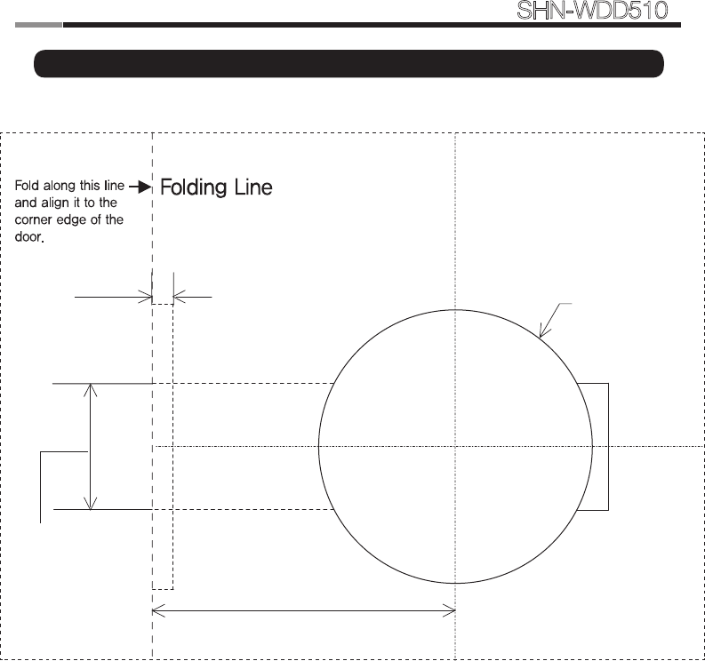
| Drilling Template Sheet : 2-3/8″(60mm) Backset
5/32" Deep
Bore 1"DIA.
Latch Hole.
2-3/8
"
Ø2-1/8
"

28
Smart
Door Lock SHN-WDD510
29
28 29
Smart
Door Lock SHN-WDD510
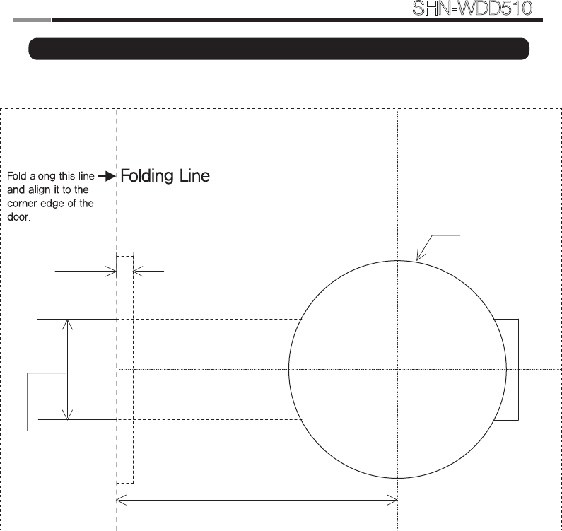
| Drilling Template Sheet : 2-3/4″(70mm) Backset
2-3/4"
Ø2-1/8"
5/32" Deep
Bore 1"DIA.
Latch Hole.

30
Smart
Door Lock SHN-WDD510
31
30 31
Smart
Door Lock SHN-WDD510
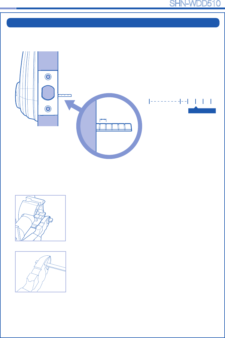
| Tailpiece Setting
• Tailpiece drawing
1. Press the V-cut line with pincers to make
more cut line.
2. Hold the the end of the tailpiece with pincers.
3. Bend it up and down until it is separated.
How to cut
cutting point
1. Check the thickness of your door.
2. According to your door thickness, cut the
tailpiece.
Note: Cut the tailpiece 5mm longer than the
door thickness.
Thickness of the door
5mm

SAMSUNG SDS
SAMSUNG SDS Co.,Ltd., reserves the right to change availability of any item in this catalog, its design,
construction, and/or its materials.
Copyright © 2014, SAMSUNG SDS Co.,Ltd. All right reserved.
Reproduction in whole or in part without the express written permission of SAMSUNG SDS is
prohibited.
GC68-02099A ED:02
Product information and customer service contact
Smart
Door Lock SHN-WDD510