Samsung SDS SHS-3320 Low Power Communication Device Transmitter User Manual manual
Samsung SDS Co., Ltd. Low Power Communication Device Transmitter manual
UserManual.wiki
>
Samsung SDS
>
SHS 3320 User Manual
manual
Navigation menu
Upload a User Manual
Namespaces
Wiki Guide
HTML
PDF
Info
Views
User Manual
Discussion / Help
Navigation
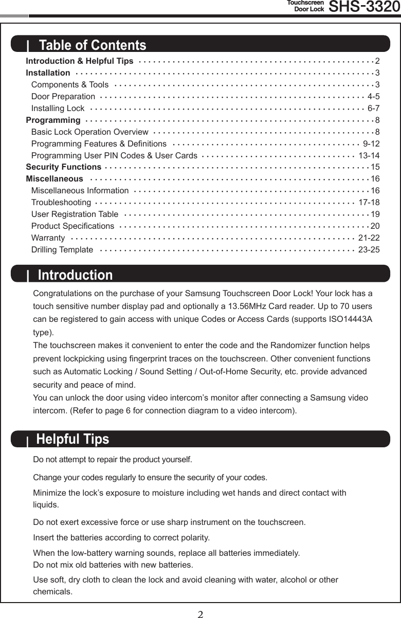
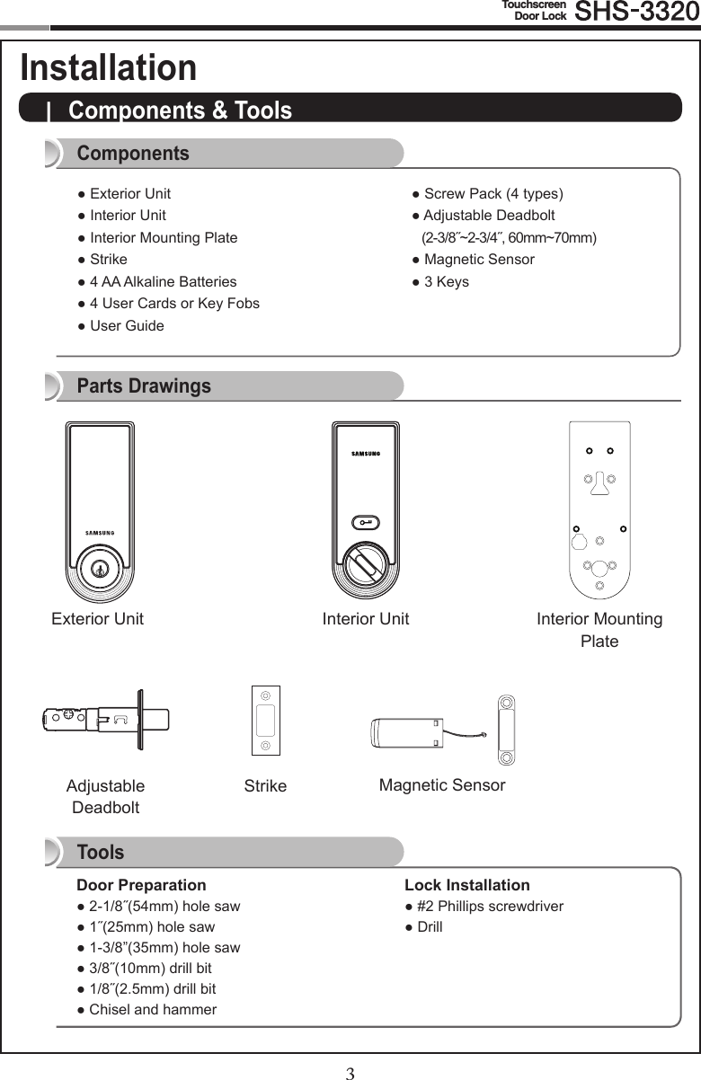
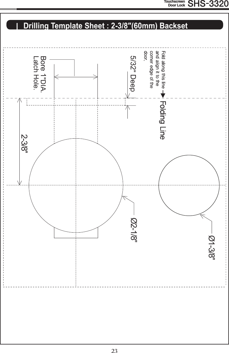
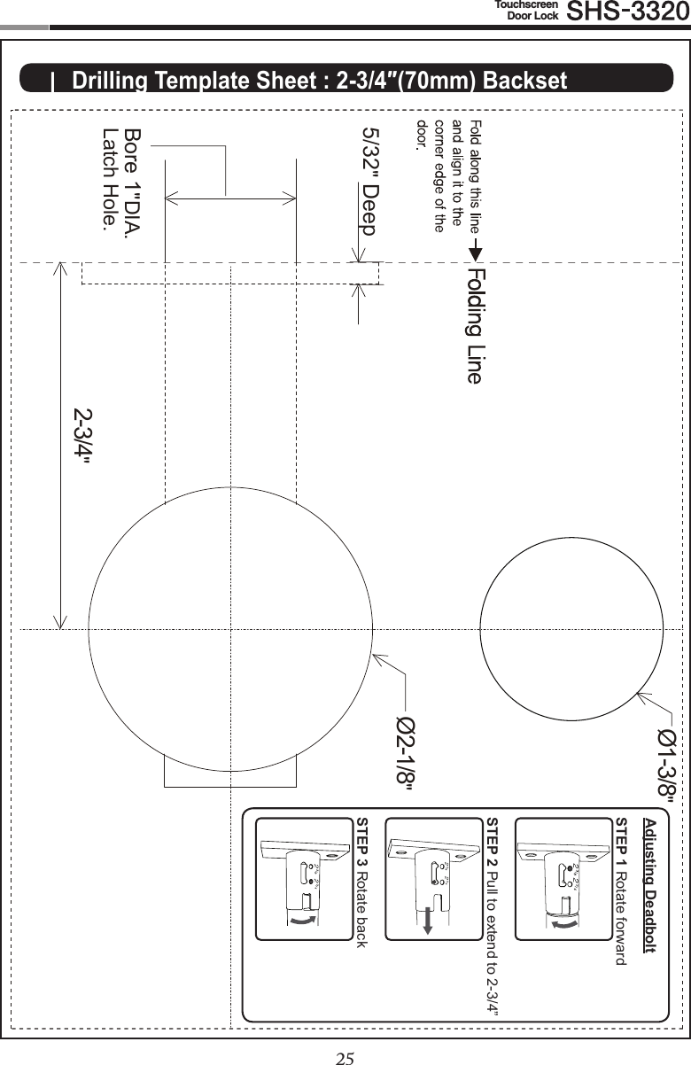
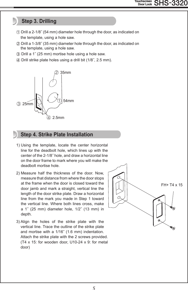
![4TouchscreenDoor Lock5| Door PreparationStep 1. Check the Door Status1) Thislocksupportsdoorthicknessof1-7/32˝to1-9/16˝(31to40mm).2) Using the provided lock template, ensure that there are no obstructions that would prevent installing the lock properly. 3) Take note of which orientation the deadbolt will need to be installed, left hand or right hand.Check the location and direction of the deadbolt, attach the drilling template (page 23) on the side of the door, and mark on it with a pen.① Align the horizontal line across the door.② Align the vertical line over the door.③ Mark the centers of the holes with the drilling template.④ Mark the centerline of the deadbolt by aligning it with the vertical line.Right-handed DoorWhen viewed from the Out-side, the hinge is on the right. Please, be aware of that there has be more than 50mm gap between the door frame and the external power contact to place the 9V battery for temporary access.Left-handed DoorWhen viewed from the Outside, the hinge is on the left.Step 2. Mark on the DoorRight-handed SettingConnect the magnetic sensor to ‘Right Trigger’.Left-handed SettingConnect the magnetic sensor to ‘Left Trigger’.The hand type is not set by default and it is set to the direction where the magnetic is detected.In order to change the hand type when it is already set, change the connection of the magnetic sensor.And press the [OPEN/CLOSE] button while the magnet is detected.Note: Please, cut the tail of the rubber pad to the direction where magnetic sensor is placed.Right TriggerLeft Trigger](https://usermanual.wiki/Samsung-SDS/SHS-3320/User-Guide-1561847-Page-4.png)
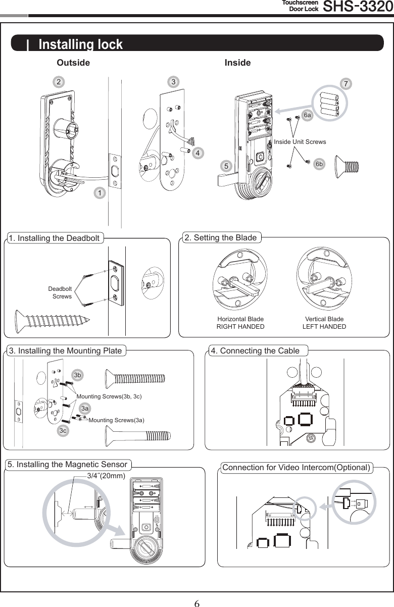
![67TouchscreenDoor Lock1. Installing the Deadbolt1) Insert the deadbolt from the side of the door.2) Fix the deadbolt using two FH+T4 x 25 screws. (T4x25/T4x15: for wooden door, U10-24x9: for steel door)2. Setting the Blade(Ensure the Exterior Unit is aligned with the center hole of the deadbolt.)While the deadbolt is in the open position, insert the blade of the exterior unit.In the case of right-handed door, insert the blade horizontally. In the case of left-handed door, insert the blade vertically.3. Installing the Mounting Plate1) Detach the Interior Mounting Plate from the Interior Unit. 2) First, install the two OH+M4 x 22 screws (3a) 90% of the way.3) Next, fasten the Interior Mounting Plate with two FH+M5 x 20 screws (3b).4) Align the Exterior Unit with the Interior Mounting Plate and then fasten the Interior Mounting Plate using two FH+M5 x 20 screws (3c).5) Tighten all screws on the Interior Mounting Plate 100%.4. Connecting the Cable5. Installing the Magnetic Sensor (page 4)CAUTION: As the magnet fastened to the door-frame may not be detected if the gap between the magnets is too large, use the neck of the magnetic sensor to install the sensorwithin3/4″(20mm)ofthemagnet.If the magnet is not detected, automatic lock does not work.6. Fix screws for the Interior Unit.1) Align the Interior Unit on to the Interior Mounting Plate, and check that the Thumbturn lever operates correctly. (Ensure cables are arranged neatly to prevent them from getting entangled or being compressed.)CAUTION : Align the Interior Unit while the Thumbturn Lever is open position. [Right-handed] [Left-handed]2) Open the battery cover of the Interior Unit. (There are the screw grooves at the upper left and right corners.)3) Using two FH+M4 x 8 screws, fasten the upper portion of the Interior Unit (6a).4) Using two FH+M4 x 8 screws, fasten the lower portion of the Interior Unit (6b).7. Install 4 Alkaline batteries.A melody will sound when all 4 batteries are installed correctly.CAUTION: Press the [OPEN/CLOSE] button to check whether the dead bolt works properly.Connect the cable of video intercom to the Interior Unit.SHS-3320 is compatible with SHT-3006 and other Samsung video intercom sys-tems.ProceduresConnection for Video Intercom(Optional)](https://usermanual.wiki/Samsung-SDS/SHS-3320/User-Guide-1561847-Page-7.png)
![8TouchscreenDoor Lock9Enter the PIN Code and pressthe [ ] button.Successful: Ding dong Failed: Ding dong ding dong The touchscreen will illu-minate. (If the Random Se-curity function is enabled, press the 2 illuminated numbers.)The door opens within one second.Touch the [Touchscreen]. Enter the PIN Code and press the [ ] button.Successful: Ding dong dang dong Failed: Ding dong ding dong| Basic Lock Operation Overview →Opening the Door with a PIN CodeTouch the Card reader with an Access Card.Successful: Ding dong dang dong Failed: Ding dong ding dongTouch the [Touch-screen]. The door opens within one second.Opening the Door with a Card→Opening the Door in Double Authentication Mode The door opens within one second.Touch the Cardreader with anAccess Card.Successful: Ding dong dang dong Failed: Ding dong ding dongTouch the [Touch-screen]. The touchscreen will illuminate. (If the Random Security function is enabled, press the 2 illuminated numbers.)→Programming](https://usermanual.wiki/Samsung-SDS/SHS-3320/User-Guide-1561847-Page-8.png)
![TouchscreenEmergency CylinderOutside InsideRegistration ButtonBattery CoverOpen/Close ButtonThumbturn LeverExternal Power ContactRestart ButtonCard ReaderMagnetic Sensor89TouchscreenDoor Lock| Programming FeaturesSymbols Description Symbols DescriptionTouch the [Touchscreen]. Press the [ ] button. It is used to complete number entry.5Press the [Registration] button. It is used to change the PIN Code or set other functions.R: Press the [Registration] buttonbriey(~1second)R5: Press the [Registration] button for 5 secondsR10: Press the [Registration ] button for 10 seconds Enter the Master PIN Code (4~12 digits). Factory Default: 1234Press the Number buttons.105](https://usermanual.wiki/Samsung-SDS/SHS-3320/User-Guide-1561847-Page-9.png)
![10TouchscreenDoor Lock11Symbols Description Symbols DescriptionEnter the User PIN Code (4~12 digits).Repeat the process inside the rectangle.Touch the Card reader with the User Card.Press the [OPEN/CLOSE] button.Enter the User/Management Number. Can be set from 1 to 70.Sound Icon Display.Sound IndicatorsSound DescriptionFur EliseTiritiritiririririLow voltage warning soundaccompanied with [OPEN/CLOSE]buttonashingred.Ding Button input soundDing dong ding dong Error soundDing dong dang Success soundDing dong Input standby soundToot~ toot~ (10 seconds) Malfunction prevention warningTi~ ti~ ti~ ti~ (5 minutes) Intrusion Detection/Out-of-home Security warningToo~~t, too~~t Double locking sound](https://usermanual.wiki/Samsung-SDS/SHS-3320/User-Guide-1561847-Page-10.png)
![1011TouchscreenDoor LockDouble Authentication Mode : This mode requires both User Card and PIN Code to open the door, ensuring more security. However, Master PIN Code can open the door regardless of mode. To enable this mode, more than 1 User Card and PIN Code must be registered. This mode is disabled by default.Double-locking : Double-locking prevents the lock from being unlocked from the outside. You can enable it by using the [OPEN/CLOSE] button.Emergency Power Contact : Continuing to use the lock without replacing batteries when required will lead to the batteries discharging and cause the lock to malfunction. You can open the door by touching the external power contacts on the Exterior Unit with a 9V battery and then touching with the Card or entering the PIN Code.Indicator Lamp : Indicates the operational status when the Card is being read or the lock is in operation.Intrusion Detection Function : When the Interior Unit is forcibly detached while the door is locked, it is detected by the magnetic sensor and an alarm is sounded. (The function is not activated when the magnet is not used.)The Intrusion Detection function is a basic function and cannot be enabled or disabled.Locking Mode (Auto/Manual) : You can enable or disable the function for locking the door automatically when it is closed. The factory default is ‘Auto mode’. - Auto: The door is locked automatically 2 seconds after it is closed. However, it does not function if the magnet is not used or the batteries are completely discharged. - Manual: When the door does not lock automatically when it is closed, touch the [Touchscreen] or the [OPEN/CLOSE] button on the Interior Unit will lock the door. Low Voltage Indicator : Refers to the state when the operating voltage of the lock is lower thanthestandardvoltage,andactivatestheLowVoltageAlarm(“FurElise”)toindicatethatthebatteries need to be replaced. Use the Emergency Power when the batteries are completely discharged.Magnetic Sensor : Detects the opening and closing of the door.Malfunction Prevention Function (Mischief Prevention Function) : When more than 5 failed authentication attempts with unregistered PIN Codes/Cards occur, a warning sounds for 10 seconds, and the lock stops operating for 3 minutes. While lock operation is stopped, a ‘beep’ is sounded every 10 seconds and the lock is activated again automatically after 3 minutes. The Malfunction Prevention function is a basic function and cannot be enabled or disabled.Thumbturn Lever : When the batteries are completely discharged, this device is used to me-chanically lock or unlock the door from inside.Master PIN Code : You can enter only one Master PIN (4-12 digits) Code. You can register the User PIN Codes/Cards after authenticating with the Master PIN (4-12 digits) Code. You can open the door with the Master PIN Code, and the factory default is ‘1234’.OPEN/CLOSE Button : A one-touch button to open the locked door. (It is also used to lock the door from inside in the Manual locking mode.)Out-of-Home Security Function : This function prevents intrusions from outside when no one is home. Pressing the [OPEN/CLOSE] button while the Out-of-Home function is enabled sounds an alarm. You can enable this function by touch of a certain button.| Denitions](https://usermanual.wiki/Samsung-SDS/SHS-3320/User-Guide-1561847-Page-11.png)
![12TouchscreenDoor Lock13Random Security Function : This mode prevents the disclosure of the PIN Code by enter-ing the PIN Code after authenticating 2 arbitrarily selected numbers. When the buttons for 2 arbitrarily selected numbers are illuminated, pressing the 2 illuminated buttons illuminates the whole touchscreen. You can enable or disable the Random Security function. This function is enabled by default.Registration Button : This button is used to change Master PIN Code/User PIN Codes/User Cards or the lock settings. It is found below the battery cover of the Interior Unit. The length of time the [Registration] button is pressed varies depending on the function. Resetting : Deletes all registered information and restores the factory default. After resetting, change the Master PIN Code for security.Restart Button : This button resets the lock when the lock stops functioning. Registered infor-mation is not deleted.Sound Setting : The volume during the input of numbers and opening or locking of the door can be set from Level 0 ~ Level 3. The sound is muted at Level 0 and is at maximum volume at Level 3. The registration mode operates at Level 2 regardless of the sound setting.User Card : You can register up to 70 User Cards including the User PIN Codes. You can open the door with a User Card.User/Management Number : It is the same number as the registered user’s address and can be set from 1 to 70. The User Number should be managed with caution as it is used to register or delete User PIN Codes/Cards.User PIN Code : You can register up to 70 User PIN Codes (4-12 digits) including the User Cards. You can open the door with a User PIN Code.Function Factory DefaultMaster PIN Code 1234Volume Level 2User PIN Code/Card NoneLocking Mode AutoOut-of-home Security Function DisabledDouble-locking DisabledRandom Security EnabledDouble Authentication Mode DisabledSettings Master UserOpening the Door Setting Up the Sound Changing Master PIN Code Registering User PIN Code/Card Deletion of User PIN Code/Card Setting the Locking Mode Setting Out-of-home Security Setting Double-locking Setting Random Security Factory Reset Setting the Volume Setting the Double Authenti-cation Mode Scope of Master, User Settings Factory Default](https://usermanual.wiki/Samsung-SDS/SHS-3320/User-Guide-1561847-Page-12.png)
![1213TouchscreenDoor Lock| Programming User PIN Codes & User CardsNote: Pressing the [Registration] button is only available while the door is open. (Deadbolt must be unlocked.) Maximum number of user registration is 70.(UserPINCodes,UserCards,KeyFobs)Open the battery cover of the Interior Unit and press the [Registration]buttonbriey. Ding dongWhen the touchscreen is illuminat-ed, enter the current Master PIN Code (default is ‘1234’) and press the [ ] button.Successful: Ding dongFailed: Ding dong ding dongChanging the Master PIN CodeOpen the bat-tery cover of the Interior Unit and press the [Reg-istration] button briey. Ding dongWhen the touch-screen is illumi-nated, enter the current Master PIN Code (default is ‘1234’) and press the [ ] button.Successful: Ding dongFailed: Ding dong ding dongEnter a User Number (1~70) to register the User PIN Code and press the [ ] button.*Choose a User Number that has not already been used.Successful: Ding dongFailed: Ding dong ding dongEnter another User Number or press the [Registration] button to quit. Enter a new User PIN Code and press [ ] button.Successful: Ding dong dangFailed: Ding dong ding dongNote: User PIN Code must be 4~12 digits.Registering a User PIN CodeEnter the new Master PIN Code and press the [ ] button.Successful: Ding dong dangFailed: Ding dong ding dongNote: Master PIN Code must be 4~12 digits.](https://usermanual.wiki/Samsung-SDS/SHS-3320/User-Guide-1561847-Page-13.png)
![14TouchscreenDoor Lock15 Open the battery cover of the Interior Unit and press the [Registra-tion]buttonbriey. Ding dong Enter a User Number (1~70) to register the User Card code and press the [ ] button.* Choose a User Number that has not already been used.Successful: Ding dongFailed: Ding dong ding dongRegistering a User CardDeleting User PIN Code / User CardWhen the touchscreen is il-luminated, enter the current Master PIN Code (default is ‘1234’) and press the [ ] button.Successful: Ding dongFailed: Ding dong ding dongTouch the Card reader with the Card to regis-ter. Ding dong dangEnter another User Number or press the [Registration] button to quit.Open the battery cover of the Interior Unit and press and hold the [Registra-tion] button for 5 seconds.Dingdong→DingdingEnter the Master PIN Code and press the [ ] button.Successful: Ding dong Failed: Ding dong ding dongEnter the User Number (1 to 70) of the User PIN Code or Card to be deleted and press the [ ] button.Successful: Ding dong dangFailed: Ding dong ding dong](https://usermanual.wiki/Samsung-SDS/SHS-3320/User-Guide-1561847-Page-14.png)
![Press the [OPEN/CLOSE] button for 5 seconds while the door is locked.Press the [OPEN/CLOSE] button or turn the Thumbturn lever.1415TouchscreenDoor Lock When the door is closed [ ] of the touchscreen will light up.Setting the Out-of-Home Security FunctionPress the [ ] button within 3 seconds. Ding dong dangAdditional FunctionsSetting Double Locking Releasing Double Locking Mute0Sound 11Sound 22Sound 33Ding dong ding dongAuto/Manual locking 5Enable Double Authentication Mode4Disable Double Authentication Mode6Enable Random Security79Ding dong dang| Security Functions](https://usermanual.wiki/Samsung-SDS/SHS-3320/User-Guide-1561847-Page-15.png)
![16TouchscreenDoor Lock| Miscellaneous InformationReset to Factory DefaultResetting the lock will delete all registered information.Note: After Reset, let the sensor detect the magnet to set the hand type again. All registered Master and user data will be deleted, and the lock will be reset to default settings.(Refer to the Program section on Page 12 for default values.)Press the [Registration] button for 10 sec-onds.Successful: Ding dong →Dingding→DingdingEnter the current Master PIN Code, and press the [ ] button.Successful: Ding dong dangFailed: Ding dong ding dong Restart FunctionContinuing to use the lock without replacing the batteries when required will lead to lock malfunction. Touching a 9V DC battery to the external power contacts on the under-side of the Exterior Unit will allow for temporary access (continue touching the battery to the contacts until the lock is open).9V Battery Emergency Power16Note: Restarting does not delete registered information.If there is no response after touching the [Touchscreen], use a pin to press the [Restart] button on the left of the external power contact of the Exterior Unit. Note: Please, be aware of that there has be more than 50mm gap between the door frame and the external power contact to place the 9V battery for temporary access.Miscellaneous](https://usermanual.wiki/Samsung-SDS/SHS-3320/User-Guide-1561847-Page-16.png)
![16TouchscreenDoor LockWhen the lock doesn’t function correctly, please check the items below.If you can’t resolve the problem, please contact the nearest service center.Problem Resolution ReferenceThere is no power.●Checkifthebatteriesareinsertedinthecorrectpolarity.●Checkthatthebatterieshaveafullcharge.●CheckthattheExteriorUnitcablehasnotcomeloose.-I can’t change the Master PIN Code. ●There was a delay while changing the PIN Code. Thetouchscreen must be illuminated when changing the PIN Code.Also,afterenteringtherstdigit,thenextdigitmustbe entered within 10 seconds. ●Replacethebatteriesiftheyaredischarged.●Refertothe ‘Changing the MasterPINCode’section inthe user manual and try again. Ensure that the Master PIN Code is 4~12 digits long. Page 13I can’t register the User PIN Code.●TheUserNumberhasalreadybeenused.Deletethede-sired User Number and re-register.●EnsurethattheUserPINCodeis4~12digitslong.Page 13I can’t register the User Card.●TheUserNumberhasalreadybeenused.Deletethede-sired User Number and re-register.●Ensurethatthecardistouchedtothecardreaderwithin10 seconds of entering the User Number.Page 14I entered the PIN Code and pressed the [ ] button, but the door won’t open. ●Check that the registered PIN Code was entered cor-rectly. ●IfthetouchscreenilluminationturnsoffwhileenteringthePIN Code, the button input was not registered. Touch the [Touchscreen] to illuminate the touchscreen and enter the PIN Code again from the beginning. (The touchscreen illumination is turned off automatically if there is no input within 5 seconds.)Page 13 I can’t unlock the door with my Card. ●TheCardiseitherunregisteredorunrecognized.●TheCardmusttouchtheCardreadercorrectly. Page 14I can’t unlock the door with my PIN Code or Card. Check if the Double-locking function has been enabled. When this function is enabled, the lock will not open with a PIN Code or Card.Touch the [Touchscreen] when the Double-locking function is enabled causes the lock to emit a ‘Too~~t, too~~t’ sound.Page 15| Troubleshooting17](https://usermanual.wiki/Samsung-SDS/SHS-3320/User-Guide-1561847-Page-17.png)
![18TouchscreenDoor Lock19My PIN Code or Card is authenti-cated, but the door won’t open. The lock may be malfunctioning. Please contact service center. -The door won’t lock automatically when I close it.●CheckifAutoLockingisset.WhenManualLockingisset,touching the [Touchscreen] locks the door. ●Ifthedoordoesn’tlockautomaticallywhenAutoLockingis set, then the lock has been installed incorrectly. ●TheAutoLockingfunctionisnotactivatedwhenthebat-teries are completely discharged. Check if the batteries are discharged.Page 15I hear the “Too~~t, too~~t”warningsound when I touch the [Touch-screen].When the Double-Locking function is enabled, touching the [Touchscreen] issues this warning sound. Check if Double-locking is enabled, disable the function and try again.Page 15The lock issues a different melody (Fur Elise) when I activate it.The sound indicates that it is time to replace the batteries. Replace with new batteries within a week. Page 10There is no response when I touch the [Touch-screen].●Use a pin to press the hole on the right of the externalpower contact of the Exterior Unit.●Ifdoingtheabovedoesnothing,contacttheservicecen-ter.Page 16](https://usermanual.wiki/Samsung-SDS/SHS-3320/User-Guide-1561847-Page-18.png)