Samsung SDS SHS-3320 Low Power Communication Device Transmitter User Manual manual
Samsung SDS Co., Ltd. Low Power Communication Device Transmitter manual
manual
Please review all included documentation and use the product as intended. Safety precautions must be
followed to avoid personal injury or property damage.
Samsung Touchscreen Door Lock
SHS-3320
User Guide

2
Touchscreen
Door Lock
3
Introduction & Helpful Tips •••••••••••••••••••••••••••••••••••••••••••••••••2
Installation ••••••••••••••••••••••••••••••••••••••••••••••••••••••••••••••3
Components & Tools ••••••••••••••••••••••••••••••••••••••••••••••••••••••3
Door Preparation ••••••••••••••••••••••••••••••••••••••••••••••••••••••• 4-5
Installing Lock ••••••••••••••••••••••••••••••••••••••••••••••••••••••••• 6-7
Programming ••••••••••••••••••••••••••••••••••••••••••••••••••••••••••••8
Basic Lock Operation Overview ••••••••••••••••••••••••••••••••••••••••••••••8
ProgrammingFeatures&Denitions ••••••••••••••••••••••••••••••••••••••• 9-12
Programming User PIN Codes & User Cards •••••••••••••••••••••••••••••••• 13-14
Security Functions •••••••••••••••••••••••••••••••••••••••••••••••••••••••15
Miscellaneous ••••••••••••••••••••••••••••••••••••••••••••••••••••••••••16
Miscellaneous Information •••••••••••••••••••••••••••••••••••••••••••••••••16
Troubleshooting •••••••••••••••••••••••••••••••••••••••••••••••••••••• 17-18
User Registration Table •••••••••••••••••••••••••••••••••••••••••••••••••••19
ProductSpecications ••••••••••••••••••••••••••••••••••••••••••••••••••••20
Warranty ••••••••••••••••••••••••••••••••••••••••••••••••••••••••••• 21-22
Drilling Template ••••••••••••••••••••••••••••••••••••••••••••••••••••• 23-25
| Table of Contents
Congratulations on the purchase of your Samsung Touchscreen Door Lock! Your lock has a
touch sensitive number display pad and optionally a 13.56MHz Card reader. Up to 70 users
can be registered to gain access with unique Codes or Access Cards (supports ISO14443A
type).
The touchscreen makes it convenient to enter the code and the Randomizer function helps
preventlockpickingusingngerprinttracesonthetouchscreen.Otherconvenientfunctions
such as Automatic Locking / Sound Setting / Out-of-Home Security, etc. provide advanced
security and peace of mind.
You can unlock the door using video intercom’s monitor after connecting a Samsung video
intercom. (Refer to page 6 for connection diagram to a video intercom).
| Helpful Tips
| Introduction
Do not attempt to repair the product yourself.
Change your codes regularly to ensure the security of your codes.
Minimize the lock’s exposure to moisture including wet hands and direct contact with
liquids.
Do not exert excessive force or use sharp instrument on the touchscreen.
Insert the batteries according to correct polarity.
When the low-battery warning sounds, replace all batteries immediately.
Do not mix old batteries with new batteries.
Use soft, dry cloth to clean the lock and avoid cleaning with water, alcohol or other
chemicals.
Components & Tools
2
3
Touchscreen
Door Lock
| Components & Tools
Door Preparation
●2-1/8˝(54mm)holesaw
●1˝(25mm)holesaw
●1-3/8”(35mm)holesaw
●3/8˝(10mm)drillbit
●1/8˝(2.5mm)drillbit
●Chiselandhammer
Lock Installation
●#2Phillipsscrewdriver
●Drill
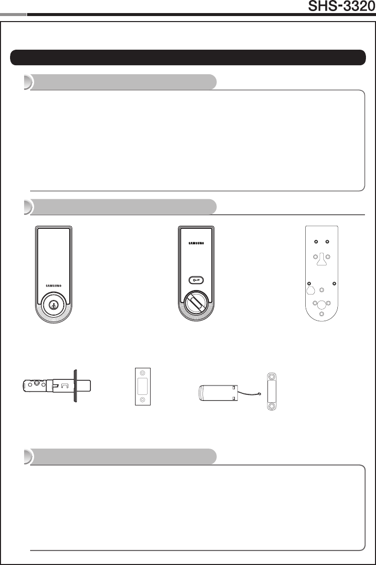
Components
Parts Drawings
Tools
Adjustable
Deadbolt
Interior Unit
Exterior Unit Interior Mounting
Plate
Strike Magnetic Sensor
●ExteriorUnit
●InteriorUnit
●InteriorMountingPlate
●Strike
●4AAAlkalineBatteries
●4UserCardsorKeyFobs
●UserGuide
●ScrewPack(4types)
●AdjustableDeadbolt
(2-3/8˝~2-3/4˝, 60mm~70mm)
●MagneticSensor
●3Keys
Components & Tools
Installation
4
Touchscreen
Door Lock
5
| Door Preparation
Step 1. Check the Door Status
1) Thislocksupportsdoorthicknessof1-7/32˝to1-9/16˝(31to40mm).
2) Using the provided lock template, ensure that there are no obstructions that would prevent
installing the lock properly.
3) Take note of which orientation the deadbolt will need to be installed, left hand or right
hand.
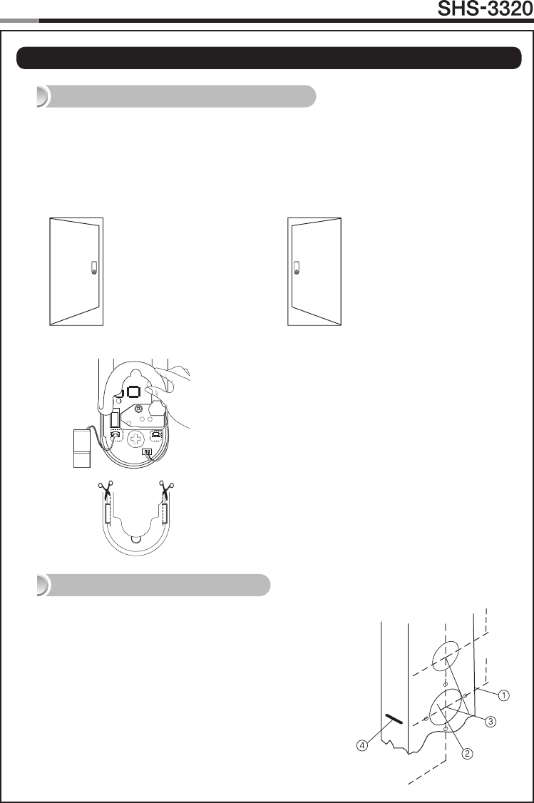
Check the location and direction of the deadbolt, attach
the drilling template (page 23) on the side of the door, and
mark on it with a pen.
① Align the horizontal line across the door.
② Align the vertical line over the door.
③ Mark the centers of the holes with the drilling template.
④ Mark the centerline of the deadbolt by aligning it with the
vertical line.
Right-handed Door
When viewed from the Out-
side, the hinge is on the right.
Please, be aware of that there
has be more than 50mm gap
between the door frame and
the external power contact to
place the 9V battery for
temporary access.
Left-handed Door
When viewed from the Outside,
the hinge is on the left.
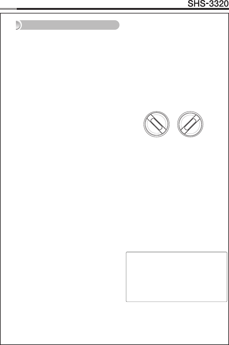
Step 2. Mark on the Door
Right-handed Setting
Connect the magnetic sensor to ‘Right Trigger’.
Left-handed Setting
Connect the magnetic sensor to ‘Left Trigger’.
The hand type is not set by default and it is set to the
direction where the magnetic is detected.
In order to change the hand type when it is already set,
change the connection of the magnetic sensor.
And press the [OPEN/CLOSE] button while the magnet
is detected.
Note: Please, cut the tail of the rubber pad to the
direction where magnetic sensor is placed.
Right Trigger
Left Trigger
4
5
Touchscreen
Door Lock
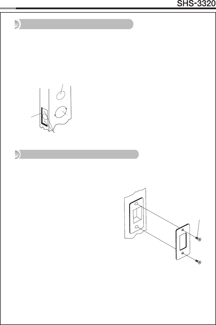
Step 3. Drilling
① Drilla2-1/8˝(54mm)diameterholethroughthedoor,asindicatedon
the template, using a hole saw.
② Drilla1-3/8˝(35mm)diameterholethroughthedoor,asindicatedon
the template, using a hole saw.
③Drilla1˝(25mm)mortiseholeusingaholesaw.
④ Drill strike plate holes using a drill bit (1/8˝,2.5mm).
1) Using the template, locate the center horizontal
line for the deadbolt hole, which lines up with the
centerofthe2-1/8˝hole,anddrawahorizontalline
on the door frame to mark where you will make the
deadbolt mortise hole.
2) Measure half the thickness of the door. Now,
measure that distance from where the door stops
at the frame when the door is closed toward the
door jamb and mark a straight, vertical line the
length of the door strike plate. Draw a horizontal
line from the mark you made in Step 1 toward
the vertical line. Where both lines cross, make
a 1˝ (25 mm) diameter hole, 1/2˝ (13 mm) in
depth.
3) Align the holes of the strike plate with the
vertical line. Trace the outline of the strike plate
andmortisewith a 1/16˝ (1.6mm)indentation.
Attach the strike plate with the 2 screws provided.
(T4 x 15: for wooden door, U10-24 x 9: for metal
door)
Step 4. Strike Plate Installation
① 54mm
② 35mm
③ 25mm
④ 2.5mm
FH+ T4 x 15
6
Touchscreen
Door Lock
7
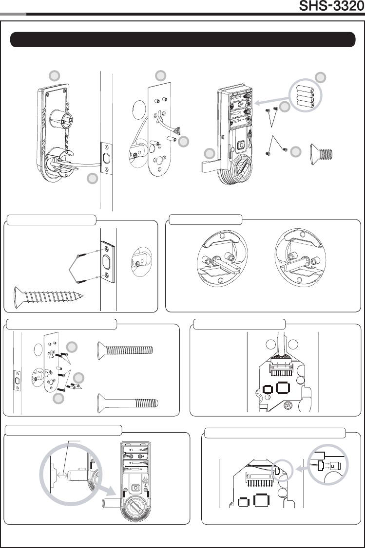
| Installing lock
Outside Inside
Deadbolt
Screws
Horizontal Blade
RIGHTHANDED
Vertical Blade
LEFT HANDED
3/4˝(20mm)
1. Installing the Deadbolt 2. Setting the Blade
3. Installing the Mounting Plate 4. Connecting the Cable
5. Installing the Magnetic Sensor Connection for Video Intercom(Optional)
Inside Unit Screws
3
2
1
7
6a
6b
5
4
3b
3a
3c
Mounting Screws(3b, 3c)
Mounting Screws(3a)
6
7
Touchscreen
Door Lock
1. Installing the Deadbolt
1) Insert the deadbolt from the side of the
door.
2) Fix the deadbolt using two FH+T4 x 25
screws. (T4x25/T4x15: for wooden door,
U10-24x9: for steel door)
2. Setting the Blade
(Ensure the Exterior Unit is aligned with the
center hole of the deadbolt.)
While the deadbolt is in the open position,
insert the blade of the exterior unit.
In the case of right-handed door, insert
the blade horizontally. In the case of left-
handed door, insert the blade vertically.
3. Installing the Mounting Plate
1) Detach the Interior Mounting Plate from
the Interior Unit.
2) First, install the two OH+M4 x 22 screws
(3a) 90% of the way.
3) Next, fasten the Interior Mounting Plate
with two FH+M5 x 20 screws (3b).
4) Align the Exterior Unit with the Interior
Mounting Plate and then fasten the
Interior Mounting Plate using
two FH+M5 x 20 screws (3c).
5) Tighten all screws on the Interior
Mounting Plate 100%.
4. Connecting the Cable
5. Installing the Magnetic Sensor
(page 4)
CAUTION: As the magnet fastened to the
door-frame may not be detected if the gap
between the magnets is too large, use the
neck of the magnetic sensor to install the
sensorwithin3/4″(20mm)ofthemagnet.
If the magnet is not detected, automatic
lock does not work.
6. Fix screws for the Interior Unit.
1) Align the Interior Unit on to the Interior
Mounting Plate, and check that the
Thumbturn lever operates correctly.
(Ensure cables are arranged neatly to
prevent them from getting entangled or
being compressed.)
CAUTION : Align the Interior Unit while
the Thumbturn Lever is open position.
[Right-handed] [Left-handed]
2) Open the battery cover of the Interior
Unit. (There are the screw grooves at the
upper left and right corners.)
3) Using two FH+M4 x 8 screws, fasten the
upper portion of the Interior Unit (6a).
4) Using two FH+M4 x 8 screws, fasten the
lower portion of the Interior Unit (6b).
7. Install 4 Alkaline batteries.
A melody will sound when all 4 batteries are
installed correctly.
CAUTION: Press the [OPEN/CLOSE]
button to check whether the dead bolt
works properly.
Connect the cable of video intercom
to the Interior Unit.
SHS-3320 is compatible with SHT-3006
and other Samsung video intercom sys-
tems.
Procedures
Connection for Video Intercom(Optional)
8
Touchscreen
Door Lock
9
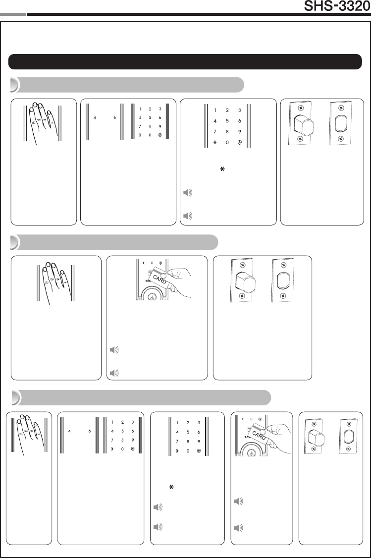
Enter the PIN
Code and press
the [ ] button.
Successful:
Ding dong
Failed:
Ding dong ding
dong
The touchscreen will illu-
minate. (If the Random Se-
curity function is enabled,
press the 2 illuminated
numbers.)
The door opens within
one second.
Touch the
[Touchscreen].
Enter the PIN Code and
press the [ ] button.
Successful:
Ding dong dang dong
Failed:
Ding dong ding dong
|
Basic Lock Operation Overview
→
Opening the Door with a PIN Code
Touch the Card reader with
an Access Card.
Successful:
Ding dong dang dong
Failed:
Ding dong ding dong
Touch the [Touch-
screen].
The door opens within one
second.
Opening the Door with a Card
→
Opening the Door in Double Authentication Mode
The door opens
within one
second.
Touch the Card
reader with an
Access Card.
Successful:
Ding dong
dang dong
Failed:
Ding dong
ding dong
Touch the
[Touch-
screen].
The touchscreen will
illuminate.
(If the Random Security
function is enabled,
press the 2 illuminated
numbers.)
→
Programming
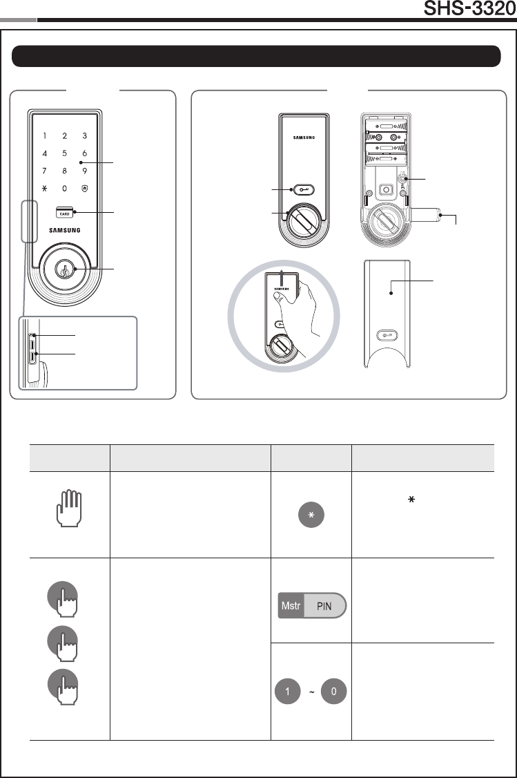
Touchscreen
Emergency
Cylinder
Outside Inside
Registration Button
Battery Cover
Open/Close Button
Thumbturn Lever
External Power
Contact
Restart Button
Card Reader
Magnetic Sensor
8
9
Touchscreen
Door Lock
| Programming Features
Symbols Description Symbols Description
Touch the [Touchscreen].
Press the [ ] button. It is
used to complete number
entry.
5
Press the [Registration]
button. It is used to change
the PIN Code or set other
functions.
R: Press the [Registration]
buttonbriey(~1second)
R5: Press the [Registration]
button for 5 seconds
R10: Press the [Registration ]
button for 10 seconds
Enter the Master PIN Code
(4~12 digits). Factory
Default: 1234
Press the Number buttons.
10
5
10
Touchscreen
Door Lock
11
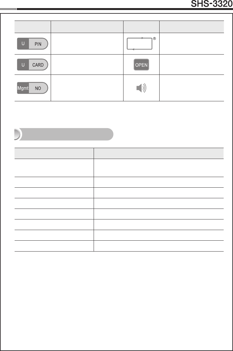
Symbols Description Symbols Description
Enter the User PIN Code (4~12
digits).
Repeat the process inside
the rectangle.
Touch the Card reader with the
User Card.
Press the [OPEN/CLOSE]
button.
Enter the User/Management
Number. Can be set from 1
to 70.
Sound Icon Display.
Sound Indicators
Sound Description
Fur Elise
Tiritiritiriririri
Low voltage warning sound
accompanied with [OPEN/CLOSE]buttonashingred.
Ding Button input sound
Ding dong ding dong Error sound
Ding dong dang Success sound
Ding dong Input standby sound
Toot~ toot~ (10 seconds) Malfunction prevention warning
Ti~ ti~ ti~ ti~ (5 minutes) Intrusion Detection/Out-of-home Security warning
Too~~t, too~~t Double locking sound

10
11
Touchscreen
Door Lock
Double Authentication Mode : This mode requires both User Card and PIN Code to open
the door, ensuring more security. However, Master PIN Code can open the door regardless of
mode. To enable this mode, more than 1 User Card and PIN Code must be registered. This mode
is disabled by default.
Double-locking : Double-locking prevents the lock from being unlocked from the outside. You
can enable it by using the [OPEN/CLOSE] button.
Emergency Power Contact : Continuing to use the lock without replacing batteries when
required will lead to the batteries discharging and cause the lock to malfunction. You can open
the door by touching the external power contacts on the Exterior Unit with a 9V battery and then
touching with the Card or entering the PIN Code.
Indicator Lamp : Indicates the operational status when the Card is being read or the lock is
in operation.
Intrusion Detection Function : When the Interior Unit is forcibly detached while the door
is locked, it is detected by the magnetic sensor and an alarm is sounded. (The function is not
activated when the magnet is not used.)The Intrusion Detection function is a basic function and
cannot be enabled or disabled.
Locking Mode (Auto/Manual) : You can enable or disable the function for locking the door
automatically when it is closed. The factory default is ‘Auto mode’.
- Auto: The door is locked automatically 2 seconds after it is closed. However, it does not function
if the magnet is not used or the batteries are completely discharged.
- Manual: When the door does not lock automatically when it is closed, touch the [Touchscreen]
or the [OPEN/CLOSE] button on the Interior Unit will lock the door.
Low Voltage Indicator : Refers to the state when the operating voltage of the lock is lower
thanthestandardvoltage,andactivatestheLowVoltageAlarm(“FurElise”)toindicatethatthe
batteries need to be replaced. Use the Emergency Power when the batteries are completely
discharged.
Magnetic Sensor : Detects the opening and closing of the door.
Malfunction Prevention Function (Mischief Prevention Function) : When more than
5 failed authentication attempts with unregistered PIN Codes/Cards occur, a warning sounds for
10 seconds, and the lock stops operating for 3 minutes. While lock operation is stopped, a ‘beep’
is sounded every 10 seconds and the lock is activated again automatically after 3 minutes. The
Malfunction Prevention function is a basic function and cannot be enabled or disabled.
Thumbturn Lever : When the batteries are completely discharged, this device is used to me-
chanically lock or unlock the door from inside.
Master PIN Code : You can enter only one Master PIN (4-12 digits) Code. You can register the
User PIN Codes/Cards after authenticating with the Master PIN (4-12 digits) Code. You can open
the door with the Master PIN Code, and the factory default is ‘1234’.
OPEN/CLOSE Button : A one-touch button to open the locked door. (It is also used to lock the
door from inside in the Manual locking mode.)
Out-of-Home Security Function : This function prevents intrusions from outside when no
one is home. Pressing the [OPEN/CLOSE] button while the Out-of-Home function is enabled
sounds an alarm. You can enable this function by touch of a certain button.
| Denitions
12
Touchscreen
Door Lock
13
Random Security Function : This mode prevents the disclosure of the PIN Code by enter-
ing the PIN Code after authenticating 2 arbitrarily selected numbers. When the buttons for 2
arbitrarily selected numbers are illuminated, pressing the 2 illuminated buttons illuminates the
whole touchscreen. You can enable or disable the Random Security function. This function is
enabled by default.
Registration Button : This button is used to change Master PIN Code/User PIN Codes/User
Cards or the lock settings. It is found below the battery cover of the Interior Unit. The length of
time the [Registration] button is pressed varies depending on the function.
Resetting : Deletes all registered information and restores the factory default. After resetting,
change the Master PIN Code for security.
Restart Button : This button resets the lock when the lock stops functioning. Registered infor-
mation is not deleted.
Sound Setting : The volume during the input of numbers and opening or locking of the door
can be set from Level 0 ~ Level 3. The sound is muted at Level 0 and is at maximum volume at
Level 3. The registration mode operates at Level 2 regardless of the sound setting.
User Card : You can register up to 70 User Cards including the User PIN Codes. You can open
the door with a User Card.
User/Management Number : It is the same number as the registered user’s address and can
be set from 1 to 70. The User Number should be managed with caution as it is used to register
or delete User PIN Codes/Cards.
User PIN Code : You can register up to 70 User PIN Codes (4-12 digits) including the User
Cards. You can open the door with a User PIN Code.
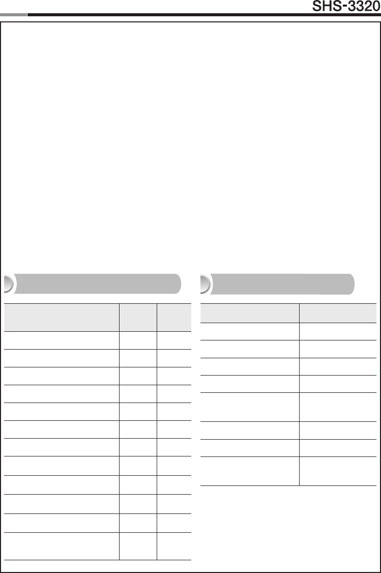
Function Factory Default
Master PIN Code 1234
Volume Level 2
User PIN Code/Card None
Locking Mode Auto
Out-of-home Security
Function Disabled
Double-locking Disabled
Random Security Enabled
Double Authentication
Mode Disabled
Settings Master User
Opening the Door
Setting Up the Sound
Changing Master PIN Code
Registering User PIN Code/Card
Deletion of User PIN Code/Card
Setting the Locking Mode
Setting Out-of-home Security
Setting Double-locking
Setting Random Security
Factory Reset
Setting the Volume
Setting the Double Authenti-
cation Mode
Scope of Master, User Settings Factory Default
12
13
Touchscreen
Door Lock
| Programming User PIN Codes & User Cards
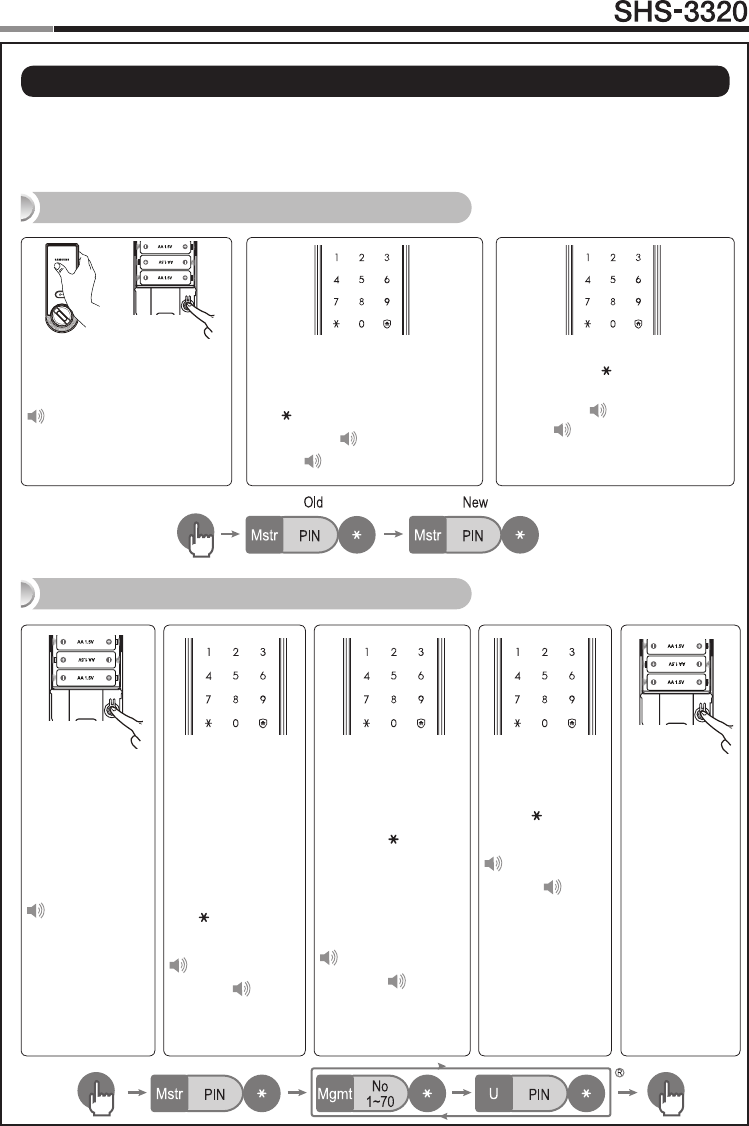
Note: Pressing the [Registration] button is only available while the door is open.
(Deadbolt must be unlocked.) Maximum number of user registration is 70.
(UserPINCodes,UserCards,KeyFobs)
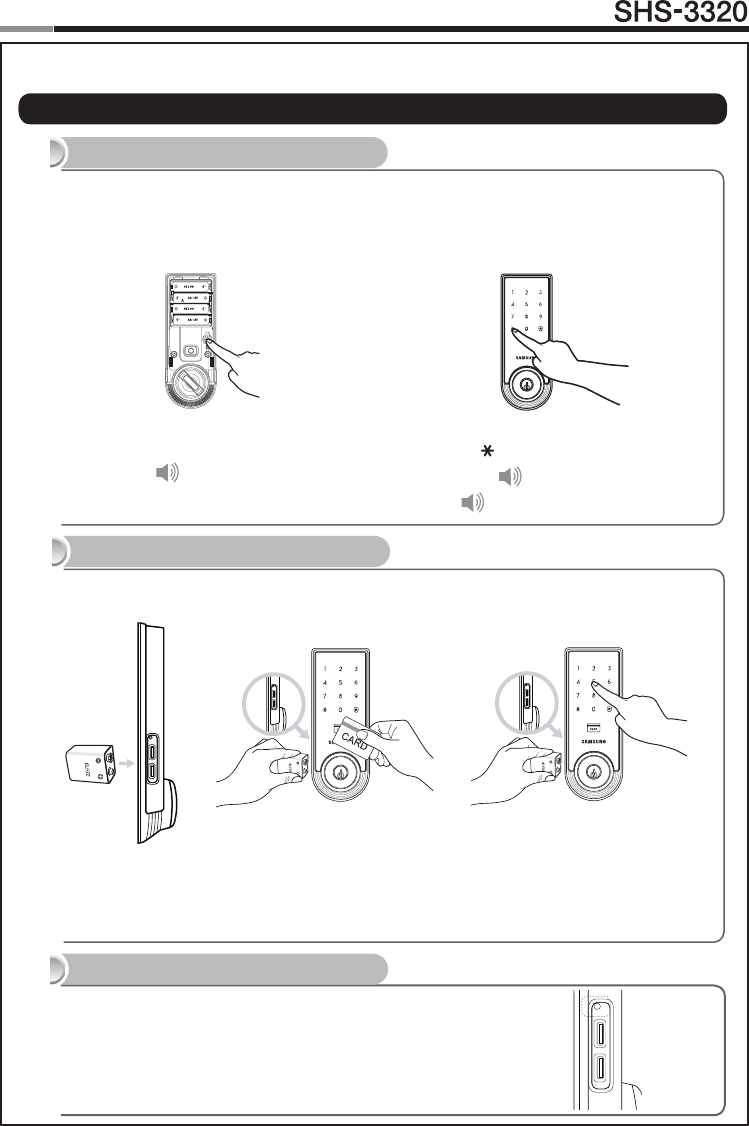
Open the battery cover of the
Interior Unit and press the
[Registration]buttonbriey.
Ding dong
When the touchscreen is illuminat-
ed, enter the current Master PIN
Code (default is ‘1234’) and press
the [ ] button.
Successful: Ding dong
Failed: Ding dong ding dong
Changing the Master PIN Code
Open the bat-
tery cover of the
Interior Unit and
press the [Reg-
istration] button
briey.
Ding dong
When the touch-
screen is illumi-
nated, enter the
current Master PIN
Code (default is
‘1234’) and press
the [ ] button.
Successful:
Ding dong
Failed: Ding
dong ding dong
Enter a User Number
(1~70) to register the
User PIN Code and
press the [ ] button.
*Choose a User
Number that has not
already been used.
Successful:
Ding dong
Failed: Ding
dong ding dong
Enter another
User Number
or press the
[Registration]
button to quit.
Enter a new User
PIN Code and
press [ ] button.
Successful:
Ding dong dang
Failed: Ding
dong ding dong
Note: User PIN
Code must be
4~12 digits.
Registering a User PIN Code
Enter the new Master PIN Code
and press the [ ] button.
Successful: Ding dong dang
Failed: Ding dong ding dong
Note: Master PIN Code must be
4~12 digits.
14
Touchscreen
Door Lock
15
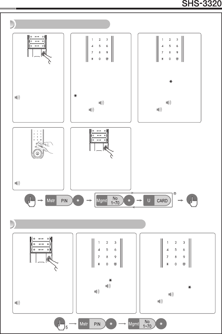
Open the battery cover
of the Interior Unit and
press the [Registra-
tion]buttonbriey.
Ding dong
Enter a User Number (1~70)
to register the User Card code
and press the [ ] button.
* Choose a User Number that
has not already been used.
Successful: Ding dong
Failed: Ding dong ding
dong
Registering a User Card
Deleting User PIN Code / User Card
When the touchscreen is il-
luminated, enter the current
Master PIN Code (default
is ‘1234’) and press the
[ ] button.
Successful: Ding dong
Failed: Ding dong ding
dong
Touch the Card reader
with the Card to regis-
ter.
Ding dong dang
Enter another User Number
or press the [Registration]
button to quit.
Open the battery cover of
the Interior Unit and press
and hold the [Registra-
tion] button for 5 seconds.
Dingdong→Dingding
Enter the Master PIN Code
and press the [ ] button.
Successful: Ding dong
Failed: Ding dong ding
dong
Enter the User Number (1 to 70) of
the User PIN Code or Card to be
deleted and press the [ ] button.
Successful: Ding dong dang
Failed: Ding dong ding dong
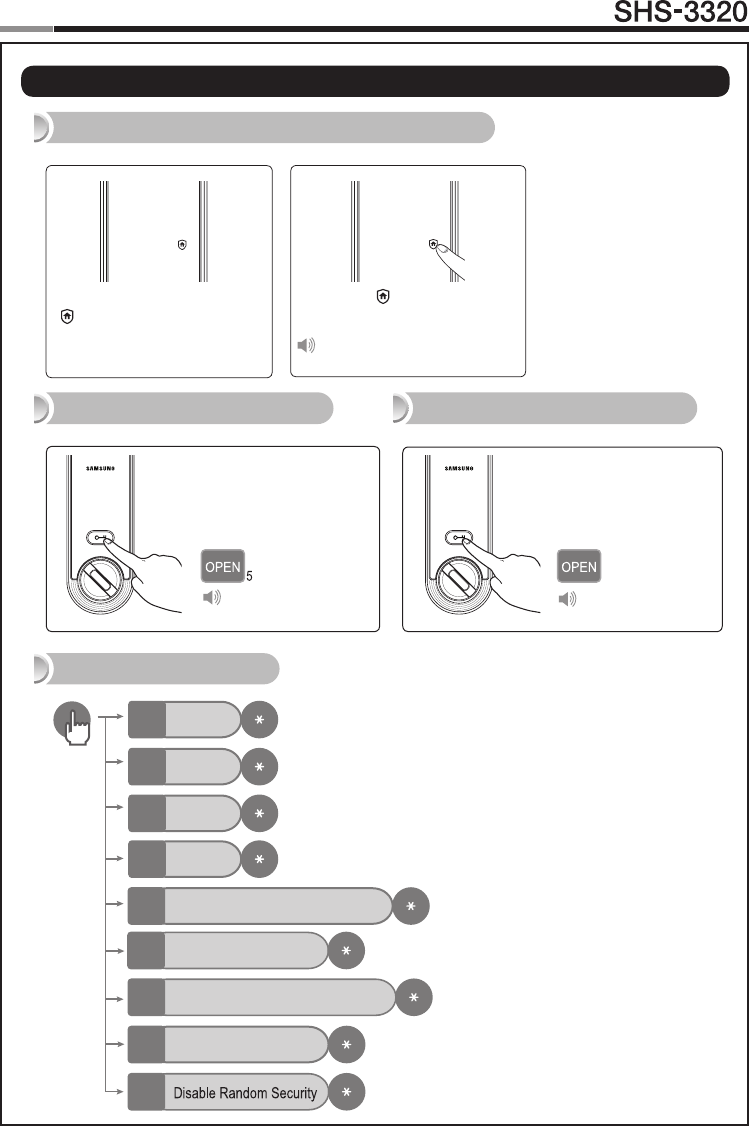
Press the [OPEN/
CLOSE] button for 5
seconds while the door
is locked.
Press the [OPEN/
CLOSE] button or turn
the Thumbturn lever.
14
15
Touchscreen
Door Lock
When the door is closed
[ ] of the touchscreen will
light up.
Setting the Out-of-Home Security Function
Press the [ ] button within
3 seconds.
Ding dong dang
Additional Functions
Setting Double Locking Releasing Double Locking
Mute
0
Sound 1
1
Sound 2
2
Sound 3
3
Ding dong ding dong
Auto/Manual locking
5
Enable Double Authentication Mode
4
Disable Double Authentication Mode
6
Enable Random Security
7
9
Ding dong dang
| Security Functions
16
Touchscreen
Door Lock
| Miscellaneous Information
Reset to Factory Default
Resetting the lock will delete all registered information.
Note: After Reset, let the sensor detect the magnet to set the hand type again.
All registered Master and user data will be deleted, and the lock will be reset to default
settings.(Refer to the Program section on Page 12 for default values.)
Press the [Registration] button for 10 sec-
onds.
Successful: Ding dong →Dingding
→Dingding
Enter the current Master PIN Code, and
press the [ ] button.
Successful: Ding dong dang
Failed: Ding dong ding dong
Restart Function
Continuing to use the lock without replacing the batteries when required will lead to lock
malfunction. Touching a 9V DC battery to the external power contacts on the under-side of the
Exterior Unit will allow for temporary access (continue touching the battery to the contacts until
the lock is open).
9V Battery Emergency Power
16
Note: Restarting does not delete registered information.
If there is no response after touching the [Touchscreen],
use a pin to press the [Restart] button on the left of the
external power contact of the Exterior Unit.
Note: Please, be aware of that there has be more than 50mm gap between the door frame
and the external power contact to place the 9V battery for temporary access.
Miscellaneous
16
Touchscreen
Door Lock
When the lock doesn’t function correctly, please check the items below.
If you can’t resolve the problem, please contact the nearest service center.
Problem Resolution Reference
There is no power.
●Checkifthebatteriesareinsertedinthecorrectpolarity.
●Checkthatthebatterieshaveafullcharge.
●CheckthattheExteriorUnitcablehasnotcomeloose.
-
I can’t change the
Master PIN Code.
●There was a delay while changing the PIN Code. The
touchscreen must be illuminated when changing the PIN
Code.Also,afterenteringtherstdigit,thenextdigitmust
be entered within 10 seconds.
●Replacethebatteriesiftheyaredischarged.
●Refertothe ‘Changing the MasterPINCode’section in
the user manual and try again. Ensure that the Master
PIN Code is 4~12 digits long.
Page 13
I can’t register the
User PIN Code.
●TheUserNumberhasalreadybeenused.Deletethede-
sired User Number and re-register.
●EnsurethattheUserPINCodeis4~12digitslong.
Page 13
I can’t register the
User Card.
●TheUserNumberhasalreadybeenused.Deletethede-
sired User Number and re-register.
●Ensurethatthecardistouchedtothecardreaderwithin
10 seconds of entering the User Number.
Page 14
I entered the PIN
Code and pressed
the [ ] button,
but the door won’t
open.
●Check that the registered PIN Code was entered cor-
rectly.
●Ifthetouchscreenilluminationturnsoffwhileenteringthe
PIN Code, the button input was not registered. Touch the
[Touchscreen] to illuminate the touchscreen and enter
the PIN Code again from the beginning. (The touchscreen
illumination is turned off automatically if there is no input
within 5 seconds.)
Page 13
I can’t unlock the
door with my Card.
●TheCardiseitherunregisteredorunrecognized.
●TheCardmusttouchtheCardreadercorrectly. Page 14
I can’t unlock the
door with my PIN
Code or Card.
Check if the Double-locking function has been enabled.
When this function is enabled, the lock will not open with
a PIN Code or Card.Touch the [Touchscreen] when the
Double-locking function is enabled causes the lock to emit a
‘Too~~t, too~~t’ sound.
Page 15
| Troubleshooting
17
18
Touchscreen
Door Lock
19
My PIN Code or
Card is authenti-
cated, but the door
won’t open.
The lock may be malfunctioning. Please contact service
center. -
The door won’t
lock automatically
when I close it.
●CheckifAutoLockingisset.WhenManualLockingisset,
touching the [Touchscreen] locks the door.
●Ifthedoordoesn’tlockautomaticallywhenAutoLocking
is set, then the lock has been installed incorrectly.
●TheAutoLockingfunctionisnotactivatedwhenthebat-
teries are completely discharged. Check if the batteries
are discharged.
Page 15
I hear the “Too~~t,
too~~t”warning
sound when I
touch the [Touch-
screen].
When the Double-Locking function is enabled, touching the
[Touchscreen] issues this warning sound. Check if Double-
locking is enabled, disable the function and try again.
Page 15
The lock issues a
different melody
(Fur Elise) when I
activate it.
The sound indicates that it is time to replace the batteries.
Replace with new batteries within a week. Page 10
There is no
response when I
touch the [Touch-
screen].
●Use a pin to press the hole on the right of the external
power contact of the Exterior Unit.
●Ifdoingtheabovedoesnothing,contacttheservicecen-
ter.
Page 16
18
19
Touchscreen
Door Lock
Management No. PIN CODE/CARD User Name Management No. PIN CODE/CARD User Name
| User Registration Table
20
Touchscreen
Door Lock
21
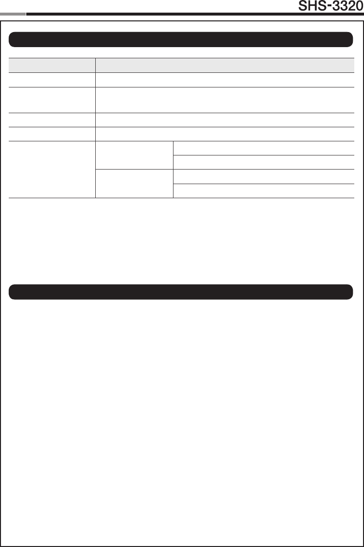
Item Specications
Voltage 4 AA Alkaline 1.5V Batteries (LR6) (6V)
Emergency Power
Source 9V Battery (6LF22) (not included)
Operation Method Electronic Control Method (PIN Code entry or Card reading)
Weight 1.8Kg(includingbothinsideandExteriorUnit)
Product Dimensions
Exterior Unit 68.0 mm (W) x 180.0 mm (H) x 29.5 mm (D)
2.67 inch (W) x 7.08 inch (H) x 1.16 inch (D)
Interior Unit 68.0 mm (W) x 180.0 mm (H) x 36.1 mm (D)
2.67 inch (W) x 7.08 inch (H) x 1.42 inch (D)
The content of this manual is subject to change without prior notice to the user in order to enhance the
performance of the product.
| Product Specications
| FCC NOTICE
NOTE : This equipment has been tested and found to comply with the limits for a Class B digital de-
vice, pursuant to part 15 of the FCC Rules. These limits are designed to provide reasonable protection
against harmful interference in a residential installation.
This equipment generates, uses and can radiate radio frequency energy and, if not installed and used
in accordance with the instructions, may cause harmful interference to radio communications. However,
there is no guarantee that interference will not occur in a particular installation. If this equipment does
cause harmful interference to radio or television reception, which can be determined by turning the
equipment off and on, the user is encouraged to try to correct the interference by one or more of the
following measures:
- Reorient or relocate the receiving antenna.
- Increase the separation between the equipment and receiver.
- Connect the equipment into an outlet on a circuit different from that to which the receiver is con-
nected.
- Consult the dealer or an experienced radio/TV technician for help.
CAUTION : Changes or modications notexpresslyapprovedbythemanufacturer responsible for
compliance could void the user’s authority to operate the equipment.

20
21
Touchscreen
Door Lock
LIMITED PRODUCT WARRANTY
Installation of the product is considered acceptance of warranty conditions
SEOUL COMMTECH CO., LTD (SEOUL COMMTECH) warrants its products to be free from
manufacturing defects in materials and workmanship for 12 months from the date of purchase.
SEOUL COMMTECH will, within said period, at its option, repair or replace any product failing to
operate correctly without charge to the original purchaser or user.
This warranty shall not apply to any equipment, or any part thereof, which has been repaired
by others, improperly installed, improperly used, abused, altered, damaged, subjected to acts
ofGod,oronwhichanyserialnumbershavebeenaltered,defacedorremoved.SEOULCOM-
MTECH does not warrant the performance or sale conditions of the seller/installer.
There are no warranties, express or implied, which extend beyond the description on the face
hereof.Thereisnoexpressorimpliedwarrantyofmerchantabilityofawarrantyoftnessfora
particular purpose. Additionally, this warranty is in lieu of all other obligations or liabilities on the
part of SEOUL COMMTECH.
Any action for breach of warranty, including but not limited to any implied warranty of merchant-
ability, must be brought within the six months following the end of the warranty period. In no case
shall SEOUL COMMTECH be liable to anyone for any consequential or incidental damages for
breach or this or any other warranty, express or implied, even if the loss or damage is caused by
the seller’s own negligence or fault.
SEOUL COMMTECH shall have no obligation under this warranty, or otherwise, if the product
has been repaired by others, improperly installed, improperly used, abused, altered, damaged,
subjectedtoaccident,nuisance,ood,reoractsofGod,oronwhichanyserialnumbershave
been altered, defaced or removed. SEOUL COMMTECH and its distributor will not be respon-
sible for any dismantling, reassembly or reinstallation charges. This warranty contains the entire
warranty. It is the sole warranty and any prior agreements or representations, whether oral or
written, are either merged herein or are expressly cancelled. SEOUL COMMTECH neither as-
sumes, nor authorizes any other person purporting to act on its behalf to modify, to change, or
to assume for it, any other warranty or liability concerning its products. In no event shall SEOUL
COMMTECH be liable for an amount in excess of SEOUL COMMTECH’s original selling price
of the product, for any loss or damage, whether direct, indirect, incidental, consequential, or oth-
erwise arising out of any failure of the product. Seller’s warranty, as hereinabove set forth, shall
not be enlarged, diminished or affected by and no obligation or liability shall arise or grow out of
Seller’s rendering of technical advice or service in connection with Buyer’s order of the goods
furnished hereunder.
SEOUL COMMTECH recommends that the entire system be completely tested weekly.
Warning: Despite frequent testing, and due to, but not limited to, any or all of the following;
criminal tampering, electrical or communications disruption, it is possible for the system to fail to
perform as expected. SEOUL COMMTECH does not represent that the product/system may not
be compromised or circumvented; or that the product or system will prevent any personal injury
orpropertylossbyburglary,robbery,reorotherwise;northattheproductorsystemwillinall
cases provide adequate warning or protection. A properly installed and maintained alarm may
onlyreduceriskofburglary,robbery,reorotherwisebutitisnotinsuranceoraguaranteethat
these events will not occur.
22
Touchscreen
Door Lock
23
Consequently, seller shall have no liability for any personal injury, property damage, or other loss
based on a claim the product failed to give warning.
Therefore, the installer should in turn advise the consumer to take any and all precautions for his
orhersafetyincluding,butnotlimitedto,eeingthepremisesandcallingpoliceorredepart-
ment, in order to mitigate the possibilities of harm and/or damage. SEOUL COMMTECH is not
an insurer of either the property or safety of the user’s family or employees, and limits its liability
for any loss or damage including incidental or consequential damages to SEOUL COMMTECH’s
original selling price of the product regardless of the cause of such loss or damage.
Some states do not allow limitations on how long an implied warranty lasts or do not allow the
exclusion or limitation of incidental or consequential damages, or differentiate in their treatment
of limitations of liability for ordinary or gross negligence, so the above limitations or exclusions
maynotapplytoyou.ThisWarrantygivesyouspeciclegalrightsandyoumayalsohaveother
rights which vary from state to state.
In case of the product defect, contact our authorized Customer Service Center. In order to exer-
cise the warranty, you must contact our authorized Customer Service Center and obtain a proper
RMA#-theproductmustbereturnedtoourauthorizedCustomerServiceCenteratuser’sship-
ping expense and the replacement product will be shipped back at our expense.
For product service, the product in all cases must be accompanied by below warranty form. Cus-
tomermustasktheresellerorinstallertolloutthewarrantyformindicatedbelow,otherwisethe
product warranty may be considered void.
Visitourwebsiteatwww.scommtech.com/enandgotoSupportmenutondthecontactinforma-
tion of our worldwide distributors.
Date of Purchase or Installation : (MM/DD/YY)
Name, telephone and full address of purchaser :
Stamp or Signature of authorized reseller / installer Product Code and Serial Number :
22
23
Touchscreen
Door Lock
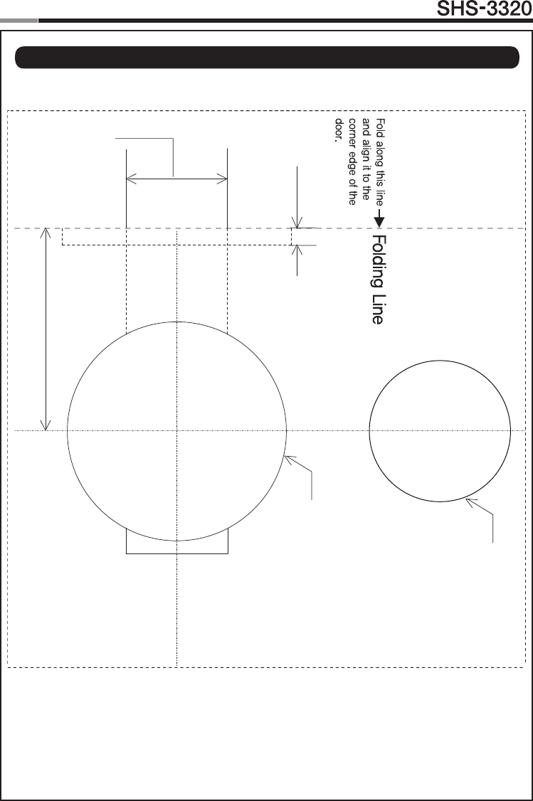
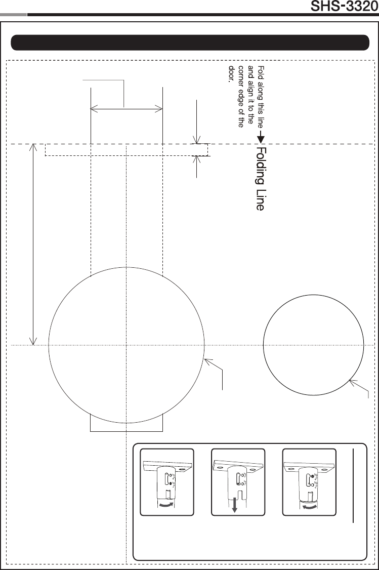
| Drilling Template Sheet : 2-3/8″(60mm) Backset
5/32" Deep
Bore 1"DIA.
Latch Hole.
2-3/8
"
Ø2-1/8
"
Ø1-3/8
"

24
Touchscreen
Door Lock
25
24
25
Touchscreen
Door Lock
| Drilling Template Sheet : 2-3/4″(70mm) Backset
2-3/4"
Ø2-1/8"
Ø1-3/8"
5/32" Deep
Bore 1"DIA.
Latch Hole.
S
TEP 1 Rotate forward
STEP 2 Pull to extend to 2-3/4”
STEP 3 Rotate back
Adjusting Deadbolt

26
Touchscreen
Door Lock
26

SEOUL COMMTECH
SEOUL COMMTECH Co.,Ltd., reserves the right to change availability of any item in this catalog, its
design, construction, and/or its materials.
Copyright © 2011, SEOUL COMMTECH Co.,Ltd. All right reserved.
Reproduction in whole or in part without the express written permission of SEOUL COMMTECH is
prohibited.
GC68-01765AED:01
Product information and customer service contact