Samsung SDS SST-US-URFR01A UHF RFID READER User Manual
Samsung SDS Co., Ltd. UHF RFID READER Users Manual
UserManual.wiki
>
Samsung SDS
>
SST US URFR01A User Manual
Users Manual
Navigation menu
Upload a User Manual
Namespaces
Wiki Guide
HTML
PDF
Info
Views
User Manual
Discussion / Help
Navigation
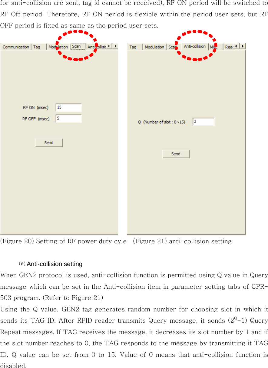
![(Figure 18) Tag type setting (Figure 19) Selection of modulation parameters ⒞ Selection of modulation parameters Modulation parameters can be set in modulation tab. (Refer to Figure 19) The modulation tab is only used when selected TAG type is GEN2. Configurable parameters of modulation are TARI, RTCal, TRCal, Reverse link encoding method, Divide ratio (DR), and pilot tone. TARI, RTCal, TRCal value is set by the micro second. Reverse link encoding method can be FM0, Miller2, Miller3, Miller8, but now the CPR-503 reader supports only Miller2 encoding. Divide ratio cab be set with 8 or 64/3. Pilot tone determines which preamble is used, short preamble or long preamble. By default, TARI is set to 12micro seconds, RTCal is set to 33mirco seconds, TRCal is set to 66micro seconds, Reverse link encoding is set to Miller 2, Divide ratio is set to 64/3 and Pilot tone is set to long preamble. [CAUTION] Except of a special case, do not change default modulation parameters. ⒟ Setting of duty cycles of RF power In order to set the duty cycles of RF power of a reader, the scan item can be used. RFID uses RF power which is turned on/off periodically. The period of ON/OFF state of RF power can be set with milli-second. However, if, in the RF ON period, a tag is already read or it is determined that no more tag can be read (As such a case, It will be possible that although query message and query-repeat message in all slots allocated](https://usermanual.wiki/Samsung-SDS/SST-US-URFR01A/User-Guide-1401051-Page-16.png)
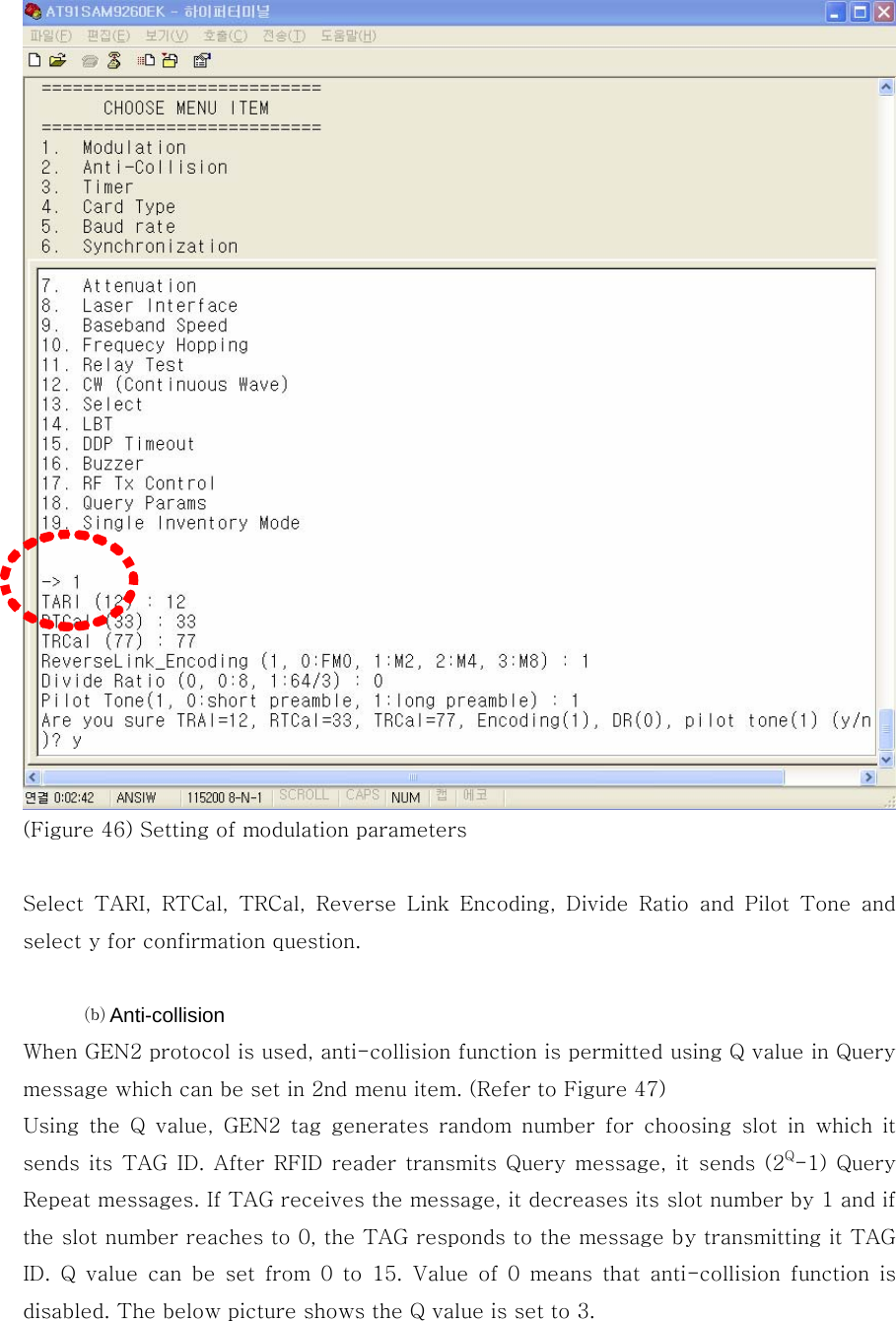
![(Figure 45) menu ⒜ Setting of modulation parameters To set modulation parameters of GEN2, press 1 and press enter key in menu. Configurable parameters of modulation are TARI, RTCal, TRCal, Reverse link encoding method, Divide ratio (DR), and pilot tone. TARI, RTCal, TRCal value is set by the micro second. Reverse link encoding method can be FM0, Miller2, Miller3, Miller8, but now the CPR-503 reader supports only Miller2 encoding. Divide ratio cab be set with 8 or 64/3. Pilot tone determines which preamble is used, short preamble or long preamble. By default, TARI is set to 12micro seconds, RTCal is set to 33mirco seconds, TRCal is set to 66micro seconds, Reverse link encoding is set to Miller 2, Divide ratio is set to 64/3 and Pilot tone is set to long preamble. The numbers in () of each item means current values. [CAUTION] Except of a special case, do not change default modulation parameters.](https://usermanual.wiki/Samsung-SDS/SST-US-URFR01A/User-Guide-1401051-Page-35.png)