Samsung SDS SST-US-URFR01A UHF RFID READER User Manual
Samsung SDS Co., Ltd. UHF RFID READER Users Manual
Users Manual
RFID Reader Manual
(SST-US-URF01A)
Index
1. Overview of UHF RFID Reader ....................................................................................... 4
2. Outer Image of Reader ....................................................................................................4
3. Outer Image of Antenna................................................................................................... 5
4. The method of power connection ................................................................................... 5
5. The method of Reader connection with Antenna............................................................6
6. Outer Interface of Reader................................................................................................7
(1) LED Indicator........................................................................................................... 7
(2) LAN..........................................................................................................................8
(3) SYNC........................................................................................................................ 8
(4) RELAY ..................................................................................................................... 9
(5) RS-422 .................................................................................................................... 9
(6) RS-485 ..................................................................................................................10
(7) RS-232 ..................................................................................................................10
(8) DEBUG...................................................................................................................11
7. The setting of serial communication mode (DIP switch setting) ...............................11
8. RFID Configuration Program .........................................................................................13
(1) Configuration of program ......................................................................................13
(2) Parameter Setting..................................................................................................14
⒜ Communication ................................................................................................ 14
⒝ Tag type setting ..............................................................................................15
⒞ Selection of modulation parameters ............................................................... 16
⒟ Setting of duty cycles of RF power ................................................................ 16
⒠ Anti-collision setting ......................................................................................17
⒡ Buzzer Setting .................................................................................................18
⒢ Reading of TAG Data ......................................................................................18
⒣ Writing TAG Data............................................................................................19
⒤ Tag Lock Setting.............................................................................................20
⒥ Reader Configuration ......................................................................................22
⒦ Synchronization Setting ..................................................................................24
⒧ Adjustment of Reader RF Output power.........................................................24
⒨ UII 쓰기 ........................................................................................................... 24
⒩ Time setting .................................................................................................... 26
⒪ Setting of TID Length .....................................................................................27
⒫ TAG Indicator..................................................................................................27
⒬ Tag Test..........................................................................................................28
(3) Displaying Tag Information...................................................................................29
(4) Program Downloading ........................................................................................... 30
(5) Reset RFID Reader ................................................................................................32
9. Test method of RFID Reader with DEBUG port ...........................................................33
(1) Communication Connection...................................................................................33
(2) Menu ...................................................................................................................... 34
⒜ Setting of modulation parameters...................................................................35
⒝ Anti-collision...................................................................................................36
⒞ Timer Setting ..................................................................................................37
⒟ Setting of TAG Type.......................................................................................38
⒠ Setting of Serial Communication Baud rate....................................................39
⒡ Synchronization ............................................................................................... 40
⒢ Adjustment of RF Power.................................................................................40
⒣ Adjustment of Laser Interface Timing............................................................41
⒤ Baseband Speed Setting..................................................................................42
⒥ Frequency Hopping Setting ............................................................................42
⒦ Relay Test .......................................................................................................44
⒧ CW (Continuous Wave) mode .........................................................................45
⒨ Select message transmission..........................................................................46
⒩ LBT setting......................................................................................................46
⒪ DDP Timeout setting....................................................................................... 47
⒫ Buzzer setting .................................................................................................47
⒬ RF Tx Control .................................................................................................48
⒭ Query Params..................................................................................................49
⒮ Single Inventory Mode ....................................................................................49
10. RFID Reader Specification........................................................................................... 50
11. RFID Antenna Specification.........................................................................................51
1. Overview of UHF RFID Reader
This product is RFID reader to transmit car information to a remote server for the
purpose of electronic toll collection system with RF technology. The reader reads car
information from TAG ID, which is embedded in TAG, and sends this information to the
remote server. This reader can be used for 4 channels if it is connected to 4 antennas
and can be used with parts of all antennas. The reader uses TCP/IP(Ethernet), RS-232
and RS-485 for transmitting TAG ID and receiving commands from and to the remote
server. Between RS-232 and RS-485, one interface is selected for being used as
communication interface and this is determined by dip switches in the MCU board. In
addition, the reader has RS-422 interface to communicate with other devices, such as
laser or camera, and has sync port to synchronize the operations of multi-readers.
Relay interface can be used to control the switch of an outer device. The debug port is
provided so that it can receive commands from user and display the status of reader.
LED interface shows the status of reader and antennas.
This product uses DC-24V.
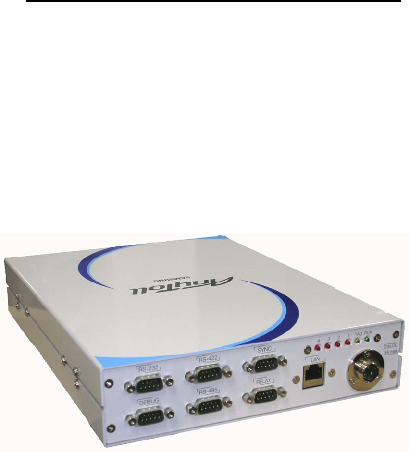
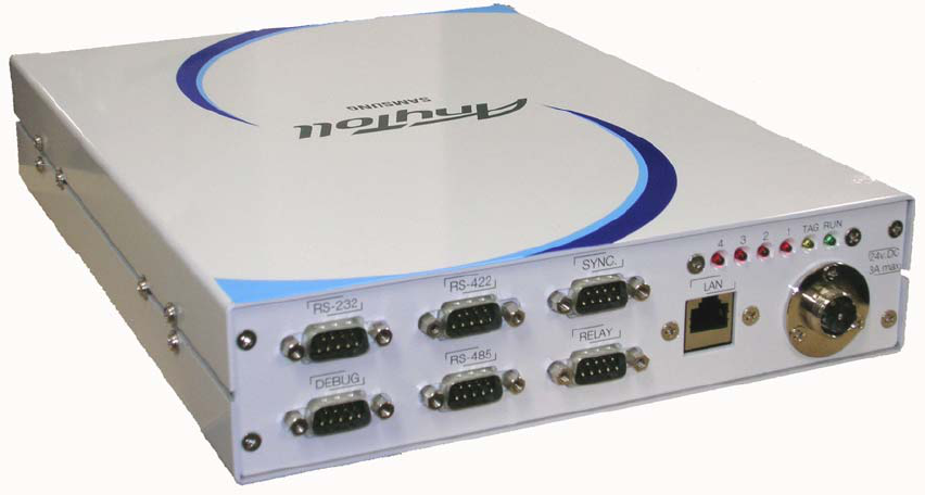
2. Outer Image of Reader
(Figure 1) RFID Reader (SST-US-URFR01A)
3. Outer Image of Antenna
(Figure 2) Antenna (SST-US-URFA01A)
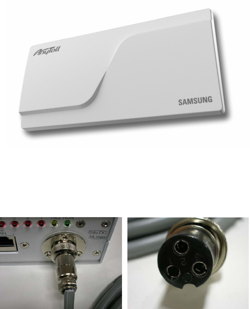
4. The method of power connection
Connect the power connector (Left of Figure3), located at the right-bottom side of a
front panel, with SMPS(DC24V) power connector (Right of Figure3).
.
(1) Connection Power connector of Reader with connector of SMPS cable
(2) Power Cable
(Figure 3) Power Connection of RFID Reader
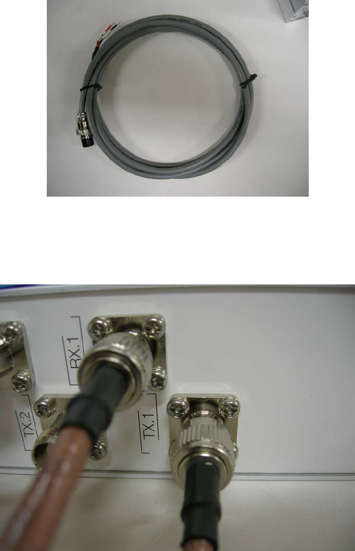
5. The method of Reader connection with Antenna
(1) Antenna connector of Reader
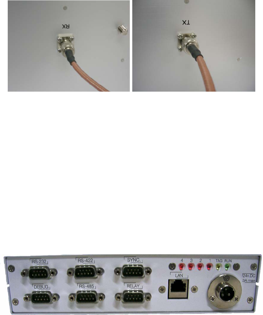
(2) Connector of Antenna
(그림4) Connection of RFID Reader with Antenna
As in Figure 4 (1), Connect Rx, Tx TNC connector with Rx, Tx connector of Antenna
with antenna cable. The reader has total 4 antenna connector ports and each port has
Rx, Tx port separately. The Figure shows the first antenna is selected. Connect Rx
connector of reader's antenna port to Rx connector in an antenna and connect Tx
connector of reader's antenna port to Tx connector in an antenna. When all antennas
are not selected, it is safe to connect dummy loads to unconnected antenna ports in a
reader (Antenna selection is made in configuration menu of CPR503 program. Refer to
Figure 29). If RF signal is output through unconnected antenna port, it would give a
damage to a power amplifier in a reader.
6. Outer Interface of Reader
(1) LED Indicator
There are 6 leds in LED indicator interface. The RUN led lights as soon as power is
inserted into reader and it blinks every 0.5 second after CPU is booted. TAG led is
toggled on receiving Tag ID. (Tag led is operated only if buzzer option is selected as
ON) The remaining 4 red-leds indicate the antenna being used. For example, if the first
red-led lights, it tells that the 1st Antenna is being used.
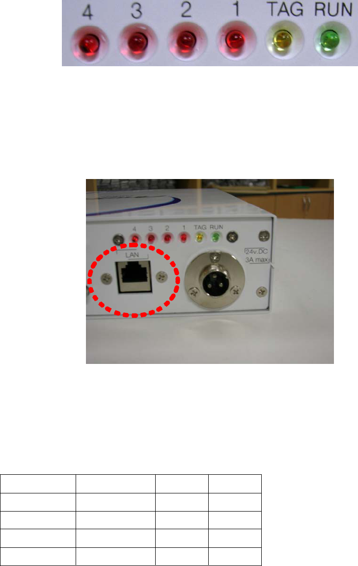
(Figure 5) LED Indicators
(2) LAN
LAN is used for communicating with a remote server. It supports up to 100Mbps. By
default, the IP address of a reader is set to 70.7.44.102.
(Figure 6) LAN Port
(3) SYNC
SYNC port is used to synchronize the readers in the case multi-readers occur the
interference to each other.
SYNC port uses the same communication method as RS-422.
2 Synchro.Z X34.3 Yellow
5 Syncro.GND X34.2 Black
3 Synchro.Y X34.1 White
6 Synchro.A X34.5 White
7 Synchro.B X34.4 Red
Table 1) DB9 pin map of SYNC port
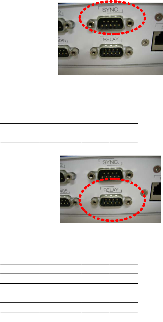
(Figure 6) SYNC port
(4) RELAY
Relay is used to control the outer device as a switch..
1 Opto.A X36.4 Yellow
2 Opto.C X36.3 White
4 Relay.1 X36.2 Red
5 Relay.2 X36.1 Black
Table 2) DB9 pin map of REALY port
(Figure 7) RELAY port
(5) RS-422
RS-422 is used to communicate with outer devices. Currently the communication speed
of RS-422 of the reader is fixed to 115200 bps.
2 RS422.Z X33.3 Yellow
5 RS422.GND X33.2 Black
3 RS422.Y X33.1 White
6 RS422.A X33.6 White
8 RS422.GND X33.5 Red
7 RS422.B X33.4 Black
Table 3) DB9 pin map of RS-422 Port
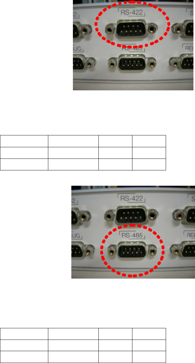
(Figure 8) RS-422 port
(6) RS-485
RS-485 is used to communicate with outer devices or a remote server. Currently the
communication speed of RS-485 of a reader is fixed to 9600bps.
7 RS485.B X32.6 Red
8 RS485.GND X32.5 Black
6 RS485.A X32.4 White
Table 4) DB9 pin map of 485 port
(Figure 9) RS-485 port
(7) RS-232
RS-232 is used to communicate with outer devices or a remote server. Currently the
communication speed of RS-232 of a reader is fixed to 9600bps
3 RS232.TX X32.8 White
2 RS232.RX X32.7 Yellow
5 GND X32.2 Black
Table 5) DB9 pin map of RS-232 port
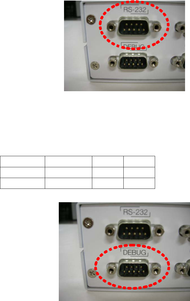
(Figure 10) RS-232 port
(8) DEBUG
DEBUG port is used when the user want to see the status of a reader or he want to
input commands to a reader. It is a console of linux device. The command input method
will be explained next chapter 9.
3 Debug.TX X31.3 White
5 Debug.GND X31.2 Black
2 Debug.RX X31.1 Yellow
Table 6) DB9 pin map of debug port
(Figure 11) DEBUG port
7. The setting of serial communication mode (DIP switch setting)
DIP switch is used to set the communication mode to RS-232 or RS-485. Only one
mode between RS-232 and RS-485 is used. If number 1, 2 switches are ON, RS-232
mode is activated and if number 3,4 switches are ON, RS-485 mode is activated.
In addition, serial communication mode is selected though CPR-503 program as the
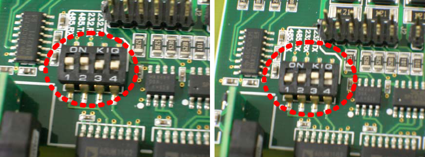
same mode as determined by DIP switches.
(1) RS-232 mode (2) RS-485 mode
(Figure 12) DIP switch setting
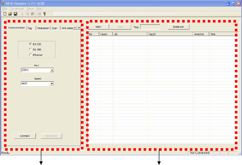
8. RFID Configuration Program
RFID Reader (CPR-503) program can be used to measure the performance of a reader
or set the configuration of a reader. It commits the functions through communication
with a reader via serial/Ethernet. As major functions, this program can set parameters
used in a reader and provide interfaces for read/write/lock functions to RFID tags.
In addition, it gives the interfaces for configuration of communication environment and
displaying the information of tags which a reader recognizes.
(1) Configuration of program
Tabs for setting parameters Window for displaying TAG information
CPR-503 program consists of 2 windows. Left windows is tabs for parameter setting,
which contains 17 items (Communication, Tag, Modulation, Scan, Anti-collision, MISC,
Read, Write, Lock, Configuration, Synchronization, Attenuation, UII write, Time, TID,
Tag indicator, Tag Test). You can select a tab using arrow button in the right corner.
Right window displays TAG information which a reader recognizes. The information
contains Serial No., the reading counter, UII, TAG ID(TID), antenna number and
reception time.
(2) Parameter Setting
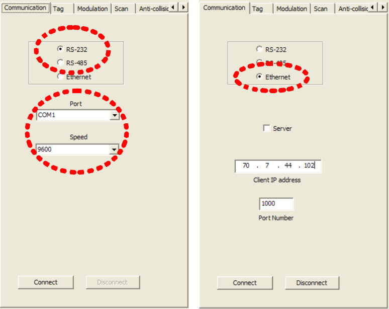
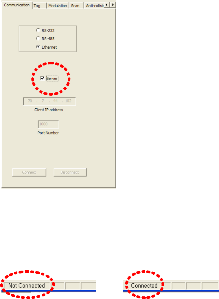
⒜ Communication
Use communication item in parameter setting tabs to configure the communication
environments. The communication method can be RS-232, RS-485 or Ethernet. The
selection is committed by pressing the radio button located in left side of each
communication method. In case of RS-232 or RS-485, the port number and baud rate
should be set, too. (Refer to Figure 14)
(Figure 14) RS-232, RS-485 Connection (Figure 15) Ethernet Connection
In Ethernet mode, the server mode or the client mode can be selected. In client mode,
IP address and port number should be set. (Refer to Figure 15) Now, the port number of
TCP is fixed to 1000. If you choose the server mode, the windows for setting IP
address and port number will be deactivated. In order to use the server mode, Server
(PC) IP address should be set in the RFID reader. (Refer to Figure 16)
(Figure 16) Ethernet (Server mode) Setting
If RS-232, RS-485 or Ethernet client mode is selected, press connect button for
communicating with a reader. In case of Ethernet server mode, it is needless to press
connect button.
When the connection is completed, the communication status indicator located in right-
bottom side of the program will display "Connected" from "Not Connected".
--Æ
(Figure 17) Communication status indicator
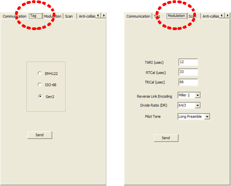
⒝ Tag type setting
RFID Reader (CPR-503) supports 3types of RFID tags. The supported types of tags are
EM-4122, ISO-6B and GEN2 among which one type should be selected using radio
button. By default, GEN2 type is selected. (Refer to Figure 18)
(Figure 18) Tag type setting (Figure 19) Selection of modulation parameters
⒞ Selection of modulation parameters
Modulation parameters can be set in modulation tab. (Refer to Figure 19) The
modulation tab is only used when selected TAG type is GEN2. Configurable parameters
of modulation are TARI, RTCal, TRCal, Reverse link encoding method, Divide ratio (DR),
and pilot tone. TARI, RTCal, TRCal value is set by the micro second. Reverse link
encoding method can be FM0, Miller2, Miller3, Miller8, but now the CPR-503 reader
supports only Miller2 encoding. Divide ratio cab be set with 8 or 64/3. Pilot tone
determines which preamble is used, short preamble or long preamble. By default, TARI
is set to 12micro seconds, RTCal is set to 33mirco seconds, TRCal is set to 66micro
seconds, Reverse link encoding is set to Miller 2, Divide ratio is set to 64/3 and Pilot
tone is set to long preamble.
[CAUTION] Except of a special case, do not change default modulation parameters.
⒟ Setting of duty cycles of RF power
In order to set the duty cycles of RF power of a reader, the scan item can be used.
RFID uses RF power which is turned on/off periodically. The period of ON/OFF state of
RF power can be set with milli-second. However, if, in the RF ON period, a tag is
already read or it is determined that no more tag can be read (As such a case, It will be
possible that although query message and query-repeat message in all slots allocated
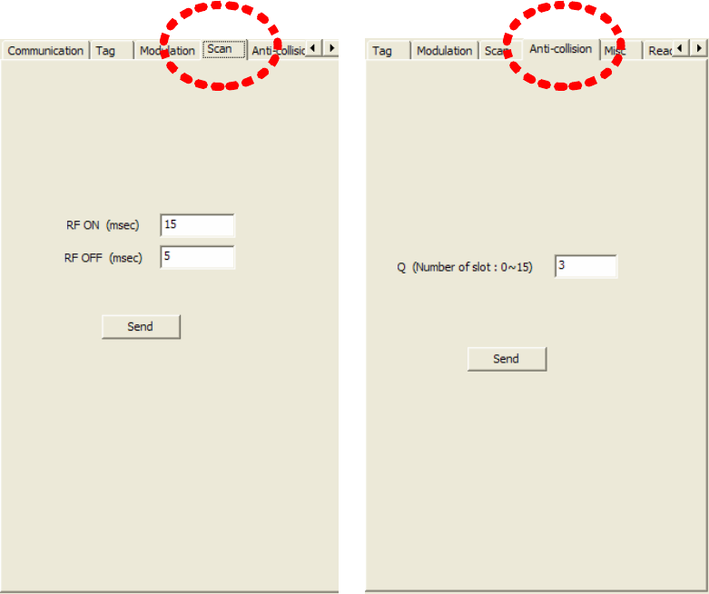
for anti-collision are sent, tag id cannot be received), RF ON period will be switched to
RF Off period. Therefore, RF ON period is flexible within the period user sets, but RF
OFF period is fixed as same as the period user sets.
(Figure 20) Setting of RF power duty cyle (Figure 21) anti-collision setting
⒠ Anti-collision setting
When GEN2 protocol is used, anti-collision function is permitted using Q value in Query
message which can be set in the Anti-collision item in parameter setting tabs of CPR-
503 program. (Refer to Figure 21)
Using the Q value, GEN2 tag generates random number for choosing slot in which it
sends its TAG ID. After RFID reader transmits Query message, it sends (2Q-1) Query
Repeat messages. If TAG receives the message, it decreases its slot number by 1 and if
the slot number reaches to 0, the TAG responds to the message by transmitting it TAG
ID. Q value can be set from 0 to 15. Value of 0 means that anti-collision function is
disabled.
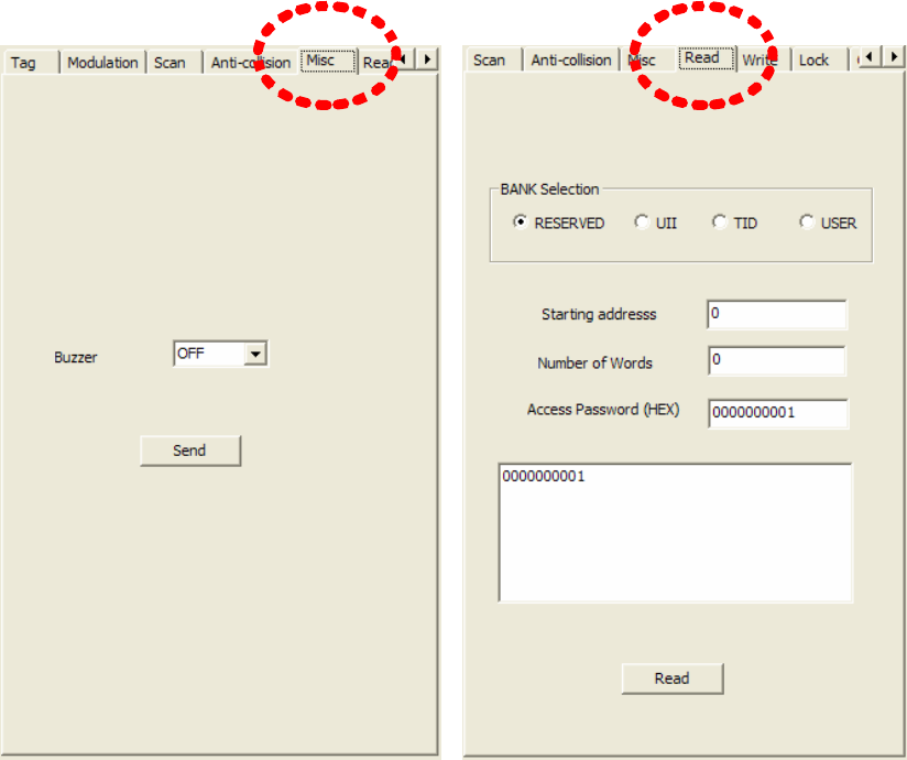
⒡ Buzzer Setting
In order to make the buzzer ring when a reader receives a TAG ID, you can set Buzzer
item in MISC tab of parameter configuration tabs. (Refer to Figure 22)
If you want to ring the buzzer on receiving the tag id, you can select ON in combo
button, and if you want the buzzer to remain silently, you can select OFF in combo
button.
(Figure 22) Buzzer Setting (Figure 23) TAG Data Reading
⒢ Reading of TAG Data
To read data in GEN2 tag, use the read item in parameter configuration tabs.
Gen2 tag has 4 memory banks. (Reserved, UII, TID and User)
To read data in each memory bank, you should choose memory bank using radio button
in bank selection and input memory start address to be read in an edit window next to
Starting address item. You should input memory size to be read by the word (2bytes)
into an edit window next to Number of Words item. If a tag uses access password,
access password should be inserted into an edit window with HEX format next to
Access Password item. If a tag don't use access password, 0 is input in that window.
If all configurable parameters for reading data in a tag are set, press Read button. When
reading is successful, the read data is displayed in the edit window between Access
password item and Read button.
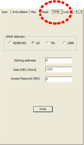
⒣ Writing TAG Data
In order to write data in GEN2 tag, use Write item in parameter configuration tabs.
(Refer to Figure 24). In case of GEN2 tag, data can be written in 4 memory banks.
To write in each 4 memory banks, choose memory bank in BANK Selection item with a
radio button and input the starting address to write in the edit window next to Starting
address item. The data to be written is inserted into edit box next to Data item. Access
password is inserted in an edit window next to Access Password item with HEX format.
If a tag don't use access password, 0 should be written in that window. If all
configurable data are input, press Write button. If the writing is successful, Write
success message will appear (Refer to Figure 25)
(Figure 24) Writing Tag Data
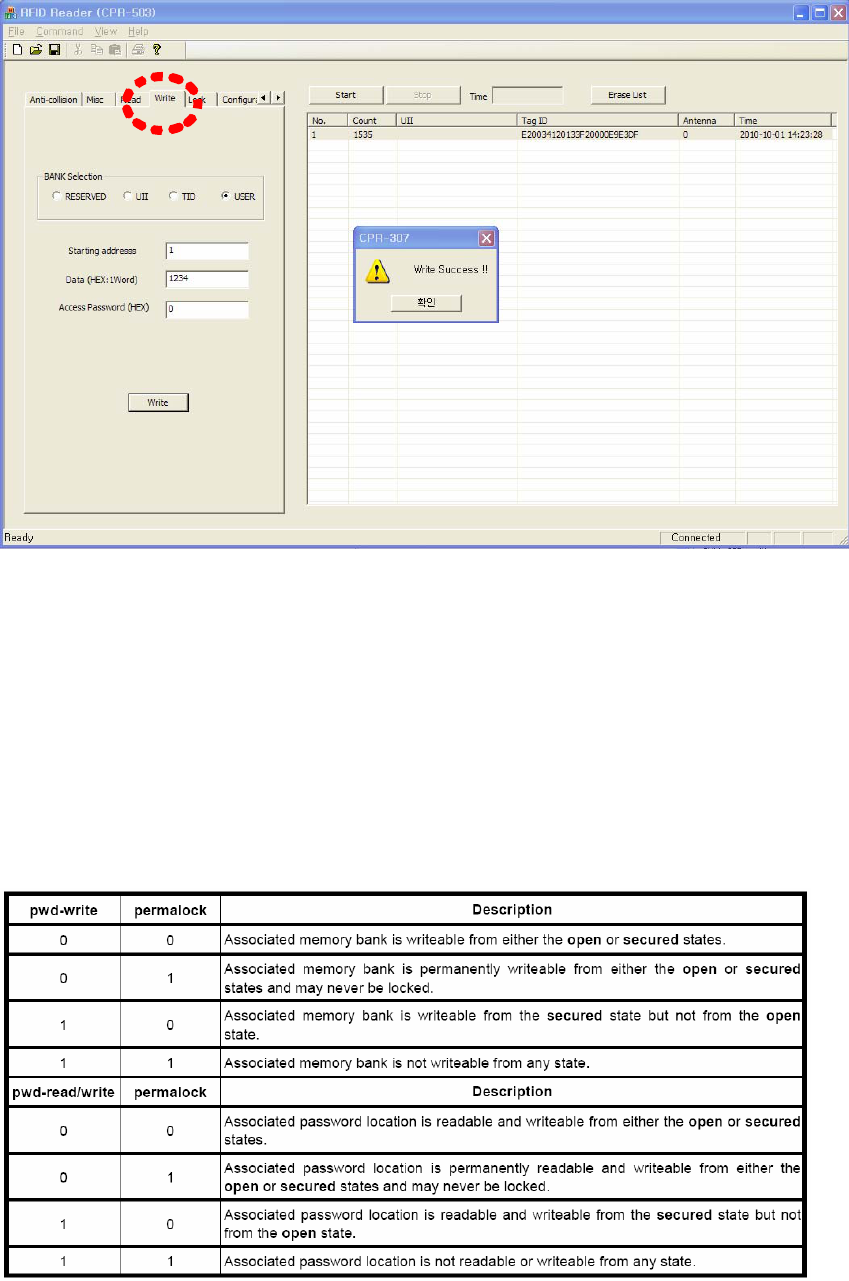
(Figure 25) Success of the writing data in a tag
⒤ Tag Lock Setting
With GEN2 tag, 4 banks can be selected for locking using Lock item in parameter
configuration tabs. (Refer to Figure 26)
Reserved memory bank can be locked in kill password memory or access password
memory. Lock status is determined with pwd-read/write item and permalock item as
follows
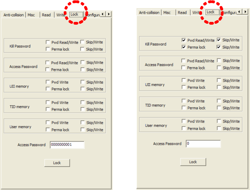
Above status is the case when Password Read/Write and Permalock is checked by
skip/write item. That is, if skip/write is checked, the lock item left to the skip/write
button is applied and if not checked, the lock status left to the skip/write item is
maintained as it was.
In case of Figure 27, it shows that Kill password is locked permanently.
(Figure 26) Locking GEN2 Tag (Figure 27) Locking Kill Password
In order to lock configuration is activated, you should press Lock button. If lock is
successful, the Lock success message window appears like Figure 28.
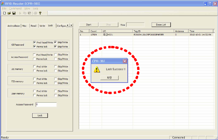
(Figure 28) Successful case of Lock
⒥ Reader Configuration
To configure the parameters of a reader, use Configuration item in parameter
configuration tabs. (Refer to Figure 29)
1) Selection of Frequency Range
To select frequency range of a reader, use a combo-box of Frequency item. The
selectable frequency ranges are KOREA, Europe and U.S. After selecting the frequency
range in combo-box, press Send button.
2) Antenna Configuration
RFID Reader (CPR-503) supports up to 4 antennas. Therefore you can choose which
antenna is used. You can select to use 4antennas, 3antennas, 2antennas or 1st antenna,
2nd antenna, 3rd antenna, 4th antenna with antenna combo box. After selecting which
antenna is used, if you press send button, the antenna configuration is completed.
3) Selecting Reader ID
After writing ID in the edit box right to the ID item, press Send button.. Up to 2 digits is
permitted as ID.
4) Configuration of serial communication
If serial communication is selected as a connection method of RFID reader with a PC, a
user can use combo-box next to the Serial Comm. item for selecting RS-232 or RS-485
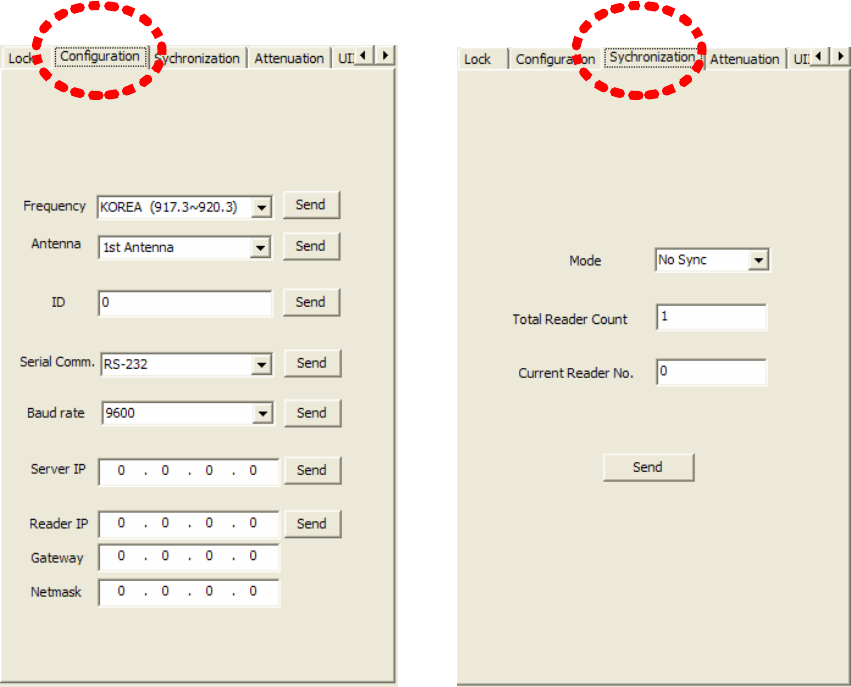
as a serial communication protocol. After setting serial communication method, if a user
presses Send button, the configuration of serial communication method between a RFID
reader and a PC is completed.
5) Baud rate setting
Combo-box next to Baud rate item is used to configure a baud rate of serial
communication. After setting a baud rate item, if a user presses Send button, the
configuration of baud rate is completed.
6) IP address setting of PC Server
When a RFID Reader (CPR-503) program is operating as a Server mode, Reader should
know of IP address of CPR-503 program. After setting IP address of server, if a user
presses Send button, the IP address setting of PC server is completed. Then, a Reader
will re-boot and try to connect to the server.
7) Changing IP address of RFID Reader
To change IP address of RFID reader, input new IP address into the Reader IP item, and
set the Gateway and Netmask. Press Send button and the IP address setting of RFID
reader will be completed.
.
(Figure 29) Setting of Reader Configuration (Figure 30) Synchronization Setting
⒦ Synchronization Setting
TBD
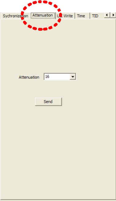
⒧ Adjustment of Reader RF Output power
To change RF power of a reader, Attenuation item in parameter configuration tabs is
used. Attenuation value is permitted from 0 to 31. The greater is the number, the less is
the RF power. That is, if attenuation value is set to 0, the RF power is maximum and if
attenuation value is set to 31, the RF power is minimum. Use combo-box next to
Attenuation item to adjust RF power and press Send button to finish the process. (Refer
to Figure 31)
(Figure 31) Adjustment of RF Power
⒨ UII 쓰기
To write data in UII memory area of GEN2 tag, UII Write item of parameter
configuration tabs can be used. (Refer to Figure 32)
The purpose is to save an information of car in UII memory for ETCS.
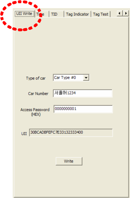
Car Type #0 ~ Car Type #9 is selected in Type of Car item to write the type of car.
That is the first byte of UII data. Input Car number in edit box of Car Number item.
Those are saved from 2nd byte of UII. If Tag is locked with an access password, input
access password into the edit box next to the Access Password item with the HEX
format or if not, input 0. UII data is made from the car type and the car number which a
user inputs.
That Hex code is displayed in UII item with text type. If input is completed, press Write
button. If a writing process is completed, the message window shows UII Write Success.
(Refer to Figure 33)
(Figure 32) Writing UII Data
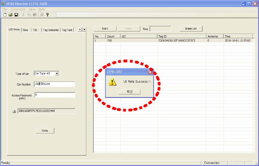
(Figure 33) The case of success in writing UII data
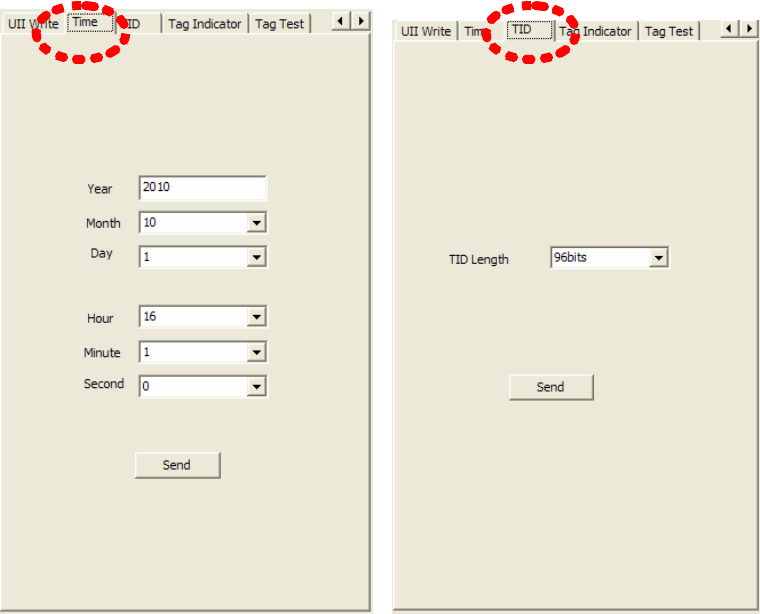
⒩ Time setting
To change the clock time of a RFID reader , use Time item of parameter configuration
tabs. Year, Month, Day, Hour, Minute and Second can be set. (Refer to Figure 34)
(Figure 34) Setting of Clock time (Figure 35) Setting of TID Length
⒪ Setting of TID Length
To determine the length of TAG ID, which is read from GEN2 tag, use the TID item of
parameter configuration tabs. The length can be 64bits or 96bits. (Refer to Figure 35)
⒫ TAG Indicator
Tag Indicator item of parameter configuration tabs shows if TAG ID is received or not.
(Refer to Figure 36)
If Show button is pressed, star(*) mark is displayed in edit box when TAG ID is
received. U indicates the CRC error when UII is received and T indicates the CRC error
when TID is received. To stop displaying indicator, press Stop button.
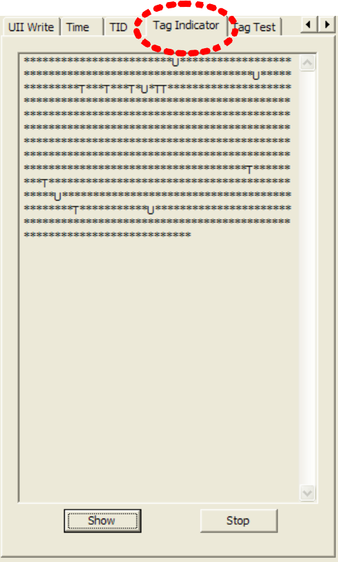
(Figure 36) Indicator of TAG ID
⒬ Tag Test
In GEN2 Tag, 2 types of IDs exist, which are UII and TID. To determine which ID is
received, use Tag Test item of parameter configuration tabs.
With Comb-box right to Mode item, Read UII, Read TID, Entrance Mode or Exit Mode
can be selected. Read UII Mode is for receiving UII only and Read TID mode is for
receiving UII and TID. Entrance Mode 와 Exit Mode is used for wring and reading User
data in User Data memory area as functions of entrance and exit of toll gate system.
Text, Location, Car Lane of User Data item contains the information of toll gate.
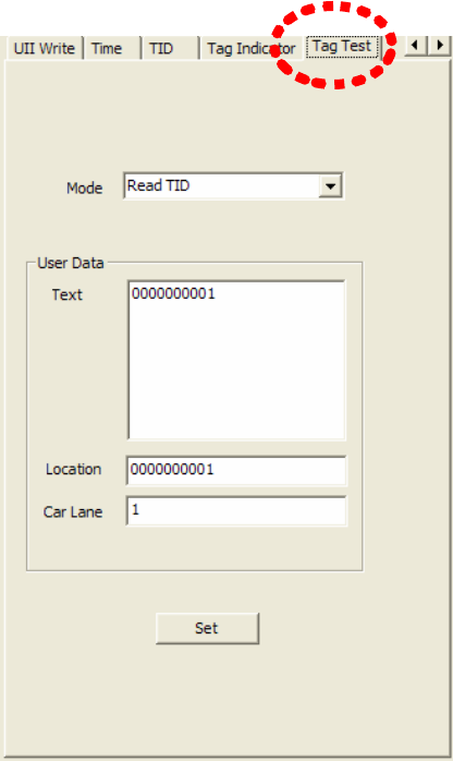
(Figure 37) Setting of Read mode of a Tag and Writing User Data
(3) Displaying Tag Information
The list item of Figure 38 indicates an information of received TAG IDs.
No. item is serial number, Count item is the number of received tags, UII item is the UII
of a tag. Tag ID indicates TID and Antenna item indicates the number of an antenna
which receives the TAG IDs. Time is the clock time when the TAG ID is received.
If Start button is pressed, the time is counted from the time when the button is pressed.
This is for the purpose of measuring how many TAG is received during the given time.
If Stop button is pressed, the reception of TAG ID is stopped.
Erase button is used for erasing the tag list.
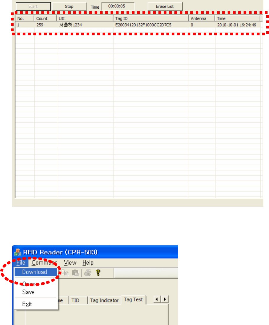
(Figure 38) Tag Information
(4) Program Downloading
(Figure 39) Window for program downloading
To download main program of RFID reader(mPROGRAM), select the Download in menu
of CPR-503 program. (Refer to Figure 39) If download button is pressed, the dialog
window for selecting file pops up. (Refer to Figure 40) If a user selects a file in this
dialog window, the file starts to be downloaded to the RFID reader and Progressive Bar
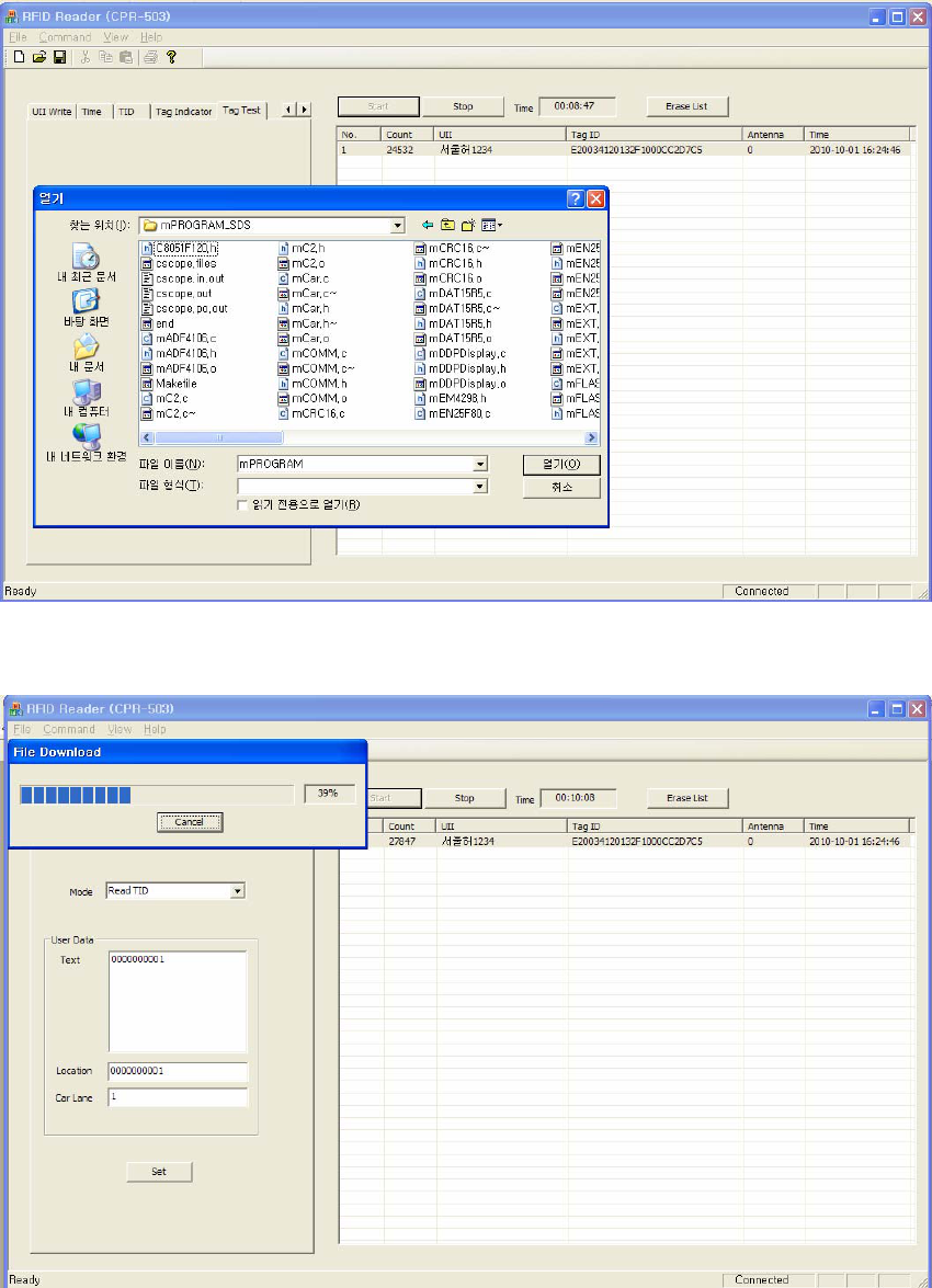
displays the percentage of process. (Refer to Figure 41) If Cancel button in Progressive
Bar is changed to OK button, it means the transmission is finished.
(Figure 40) Dialog window for selecting file
(Figure 41) Progressive Bar
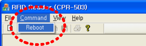
(5) Reset RFID Reader
To reset RFID reader, press Reboot button in Command item of menu. (Refer to Figure
42)
(Figure 42) Reset RFID reader
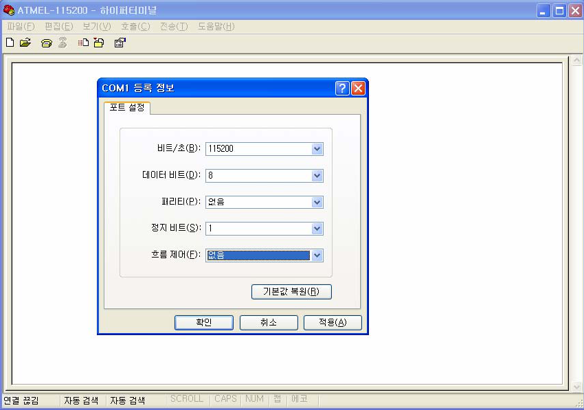
9. Test method of RFID Reader with DEBUG port
(1) Communication Connection
The procedure for parameter setting and testing for RFID reader using DEBUG port
(RS-232) is as follows.
⒜ Execute HyperTerminal and configure the communication parameters.
- baud rate : 115200bps
- Data bits : 8 bits
- Parity : None
- Stop bit : 1 bit
- Flow control : None
(Figure 43) Configuration of communication parameters
⒝ Connect RS-232 cable between PC and DEBUG port in RFID reader.
⒞ If connection is finished, press ENTER key and be sure that /home/frog# prompt
appears as below Figure 44 (When reader is booting, the booting message will appear
and it also means connection is completed)
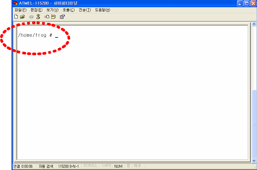
(Fiure 44) Connection of serial communication
(2) Menu
if /home/frog # prompt appears, press ./menu and press enter key. The menu like below
Figure will be displayed. (Refer to Figure 45)
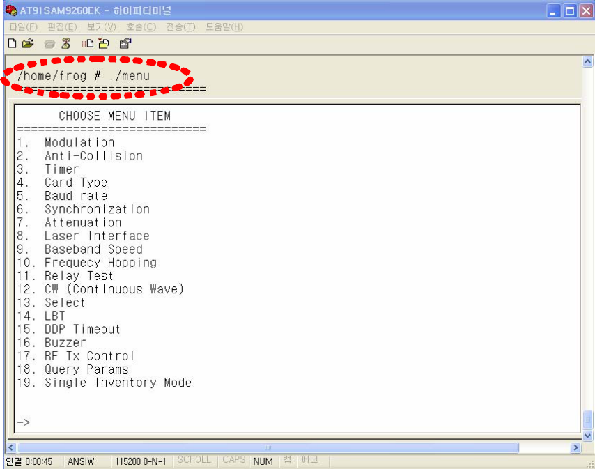
(Figure 45) menu
⒜ Setting of modulation parameters
To set modulation parameters of GEN2, press 1 and press enter key in menu.
Configurable parameters of modulation are TARI, RTCal, TRCal, Reverse link encoding
method, Divide ratio (DR), and pilot tone. TARI, RTCal, TRCal value is set by the micro
second. Reverse link encoding method can be FM0, Miller2, Miller3, Miller8, but now
the CPR-503 reader supports only Miller2 encoding. Divide ratio cab be set with 8 or
64/3. Pilot tone determines which preamble is used, short preamble or long preamble.
By default, TARI is set to 12micro seconds, RTCal is set to 33mirco seconds, TRCal is
set to 66micro seconds, Reverse link encoding is set to Miller 2, Divide ratio is set to
64/3 and Pilot tone is set to long preamble.
The numbers in () of each item means current values.
[CAUTION] Except of a special case, do not change default modulation parameters.
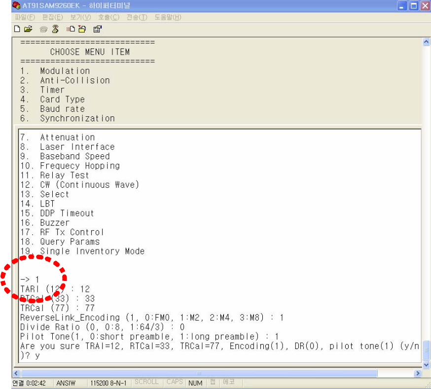
(Figure 46) Setting of modulation parameters
Select TARI, RTCal, TRCal, Reverse Link Encoding, Divide Ratio and Pilot Tone and
select y for confirmation question.
⒝ Anti-collision
When GEN2 protocol is used, anti-collision function is permitted using Q value in Query
message which can be set in 2nd menu item. (Refer to Figure 47)
Using the Q value, GEN2 tag generates random number for choosing slot in which it
sends its TAG ID. After RFID reader transmits Query message, it sends (2Q-1) Query
Repeat messages. If TAG receives the message, it decreases its slot number by 1 and if
the slot number reaches to 0, the TAG responds to the message by transmitting it TAG
ID. Q value can be set from 0 to 15. Value of 0 means that anti-collision function is
disabled. The below picture shows the Q value is set to 3.
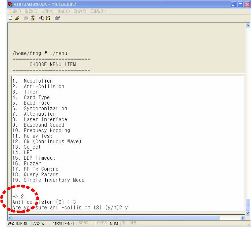
(Figure 47) Anti-collision setting
⒞ Timer Setting
In order to set the duty cycles of RF power of a reader, select 3 item in menu.
RFID uses RF power which is turned on/off periodically. The period of ON/OFF state of
RF power can be set with milli-seconds. However, if, in the RF ON period, a tag is
already read or it is determined that no more tag can be read (As such a case, It will be
possible that although query message and query-repeat message in all slots allocated
for anti-collision are sent, tag id cannot be received), RF ON period will be switched to
RF Off period. Therefore, RF ON period is flexible within the period user sets, but RF
OFF period is fixed as same as the period user sets.
Below picture shows that RF ON time was 15msec and RF Off time was 3msec and they
are changed to 20msec and 10msec respectively.
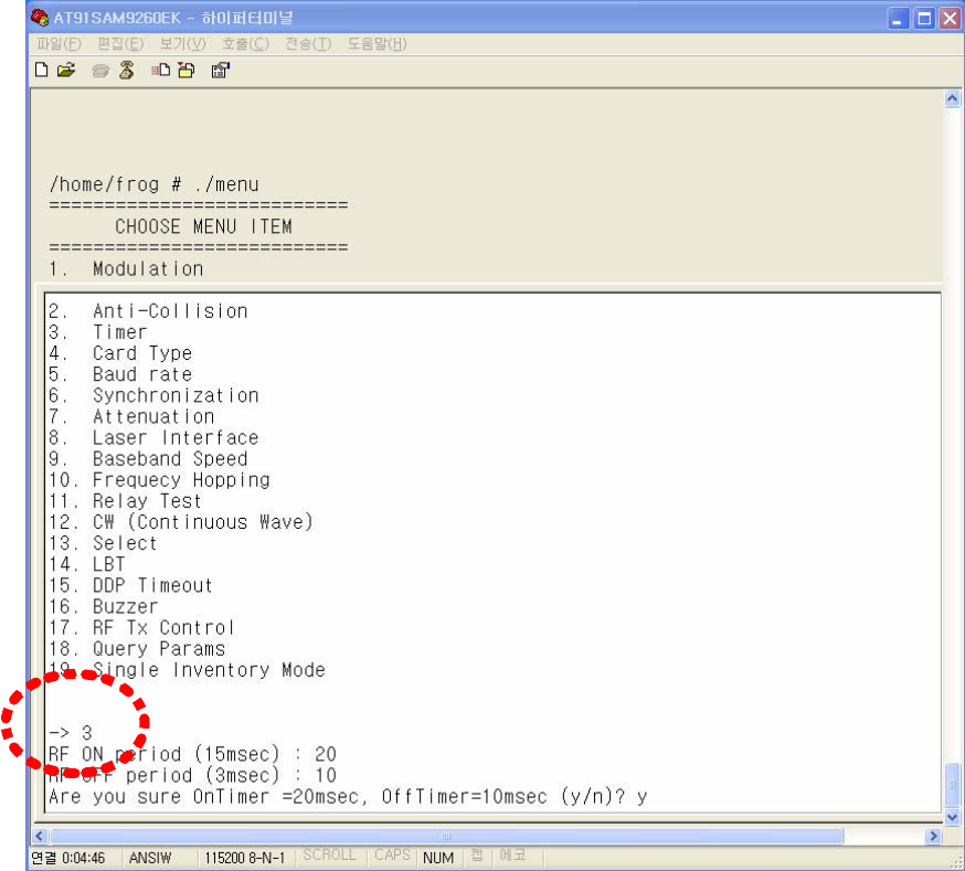
(Figure 48) Setting of Time of TAG Scan period
⒟ Setting of TAG Type
RFID Reader (CPR-503) supports 3types of RFID tags. The supported types of tags are
EM-4122, ISO-6B and GEN2, among which one type should be selected using 4th item
in menu. By default, GEN2 type is selected. Figure 49 shows that Tag type is changed
from GEN2 type to ISO-6B.
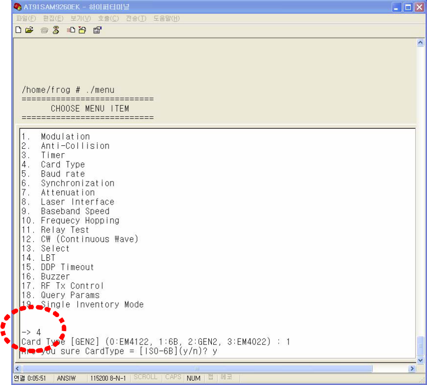
(Figure 49) Setting of Tag Type
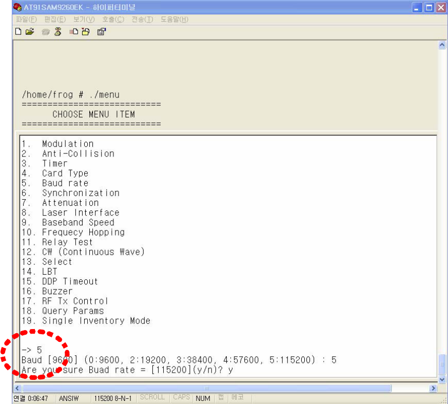
⒠ Setting of Serial Communication Baud rate
Select 5th item in menu to set baud rate for serial communication.
Supported speeds are 9600bps, 19200bps, 38400bps, 57600bps and 115200bps.
Figure 50 shows that baud rate is changed from 9600bps to 115200bps.
(Figure 50) Setting of Serial communication speed
⒡ Synchronization
TBD
⒢ Adjustment of RF Power
To change RF power of Reader, 7th item in menu is used. Attenuation value is permitted
from 0 to 31. The greater is the number, the less is the RF power. That is, if attenuation
value is set to 0, the RF power is maximum and if attenuation value is set to 31, the RF
power is minimum.
Figure 51 shows attenuation value is changed from 16 to 0.
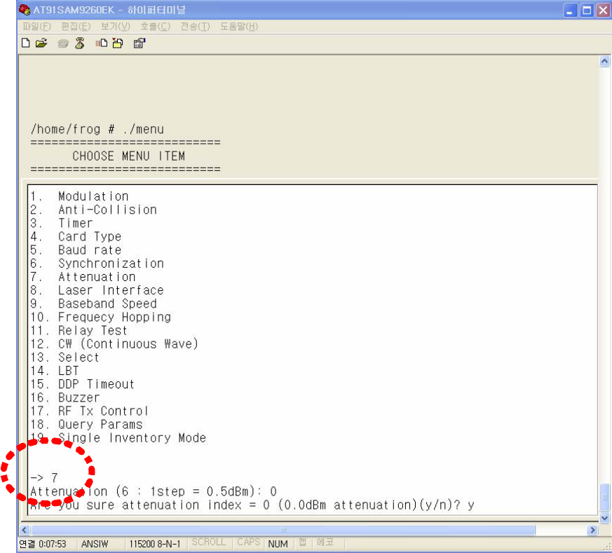
(Figure 51) Adjustment of RF Power
⒣ Adjustment of Laser Interface Timing
TBD
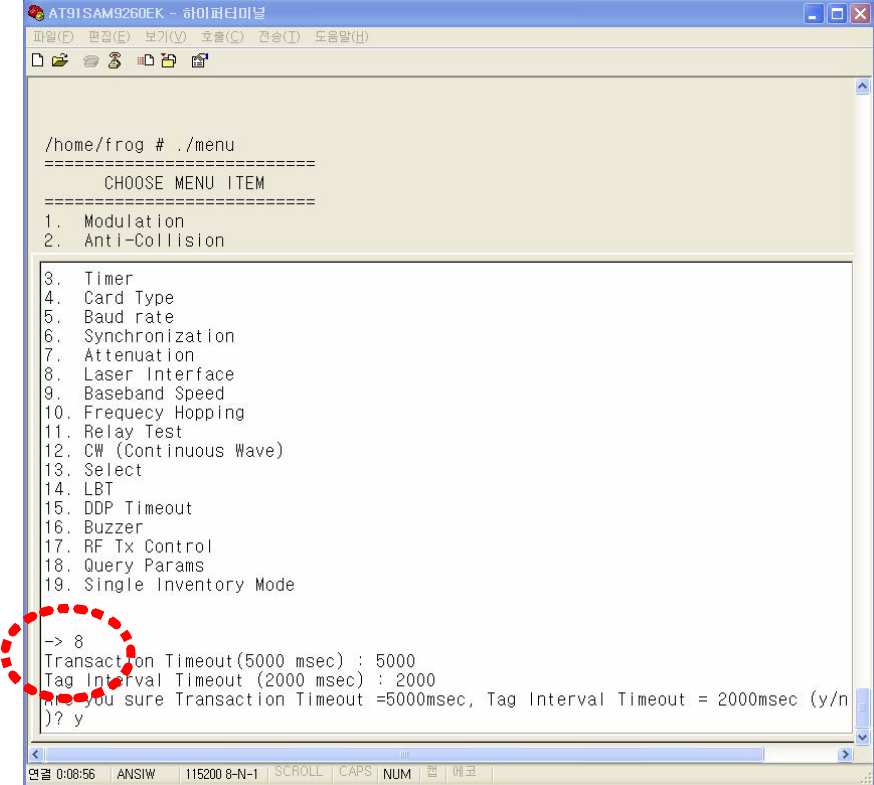
(Figure 52) Transaction Timeout and Tag Interval Timeout
⒤ Baseband Speed Setting
TBD
⒥ Frequency Hopping Setting
To set Frequency Hopping mode, select 10th item in menu. (Refer to Figure 53)
If 1 is set to Use Frequency Hopping item, a reader becomes frequency hopping mode.
To fix the frequency, Set 0 to Use Frequency Hopping item and select channel number.
Figure 54 shows that the frequency is fixed to 1st channel.

(Figure 53) Setting of frequency hopping mode
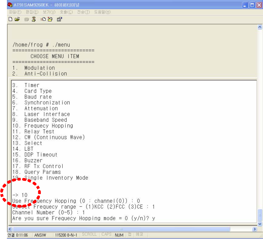
(Figure 54) Setting of fixed frequency mode
⒦ Relay Test
To make Relay ON/OFF, use 11th item in menu.
If 1 is selected in RELAY item, Relay becomes ON, and if 0 is selected, Relay becomes
OFF.
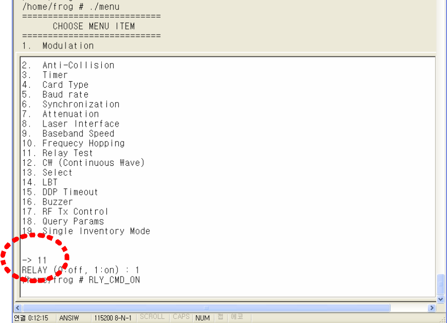
(Figure 55) Relay menu
⒧ CW (Continuous Wave) mode
To set RF Continuous Wave mode which don’t modulate RF signal, use 12th item in
menu. If 1 is selected in CW Mode item, a reader operates as Continuous Wave mode
and if 0 is selected, a reader operates in normal mode which modulates RF signals.
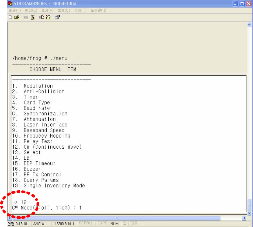
(Figure 56) CW mode setting
⒨ Select message transmission
TBD
⒩ LBT setting
To set LBT mode, use 14th item in menu.
If 1 is set in LBT mode item, LBT mode is enabled and if 0 is set, a reader operates in a
normal mode.
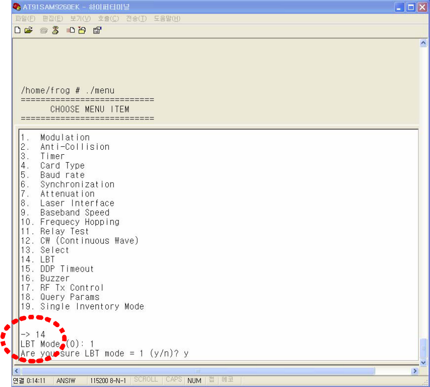
(Figure 57) LBT mode setting
⒪ DDP Timeout setting
TBD
⒫ Buzzer setting
To determine whether Buzzer rings when TAG ID is received or not, use 16th item in
menu. If 0 is set to Buzzer mode, Buzzer mode will be OFF and Buzzer will not ring
when TAG ID is received. If 1 is set to Buzzer mode, Buzzer mode will be ON and
Buzzer will ring when TAG ID is received.
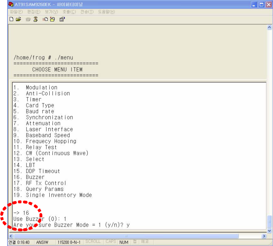
(Figure 58) Setting of Buzzer mode
⒬ RF Tx Control
To determine whether to always maintain RF power ON or always maintain RF power
OFF or set ON/OFF time period, use 17th item in menu.
If 0 is set, timing mode is enabled and a reader turns on RF power during ON time
period and turns off RF power during OFF time period. The ON/OFF timing is set in 3rd
item in menu. If 1 is set, RF power is always maintained as OFF. If 2 is set, RF power is
always maintained as ON.
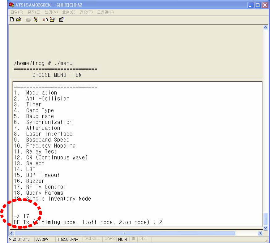
(Figure 59) Rx Tx Control mode setting
⒭ Query Params
TBD
⒮ Single Inventory Mode
TBD

10. RFID Reader Specification
Items Specification and Fucntions
Main Board
• 32bit ARM CPU
• 64M RAM
• 256M NAND Flash
Operating
Frequecy
• KCC : 917 ~ 923.5 MHz
• FCC : 902 ~ 928 MHz
• CE : 865 ~ 868 MHz
RF Output Power 27.94dBm
Channel
Bandwidth
• KCC, CE : < 200 kHZ
• FCC : < 250KHz
Frequency
Selection
• KCC, FCC: FHSS
• CE : LBT
Recognition
Distance < 10m
Indicators • LED : RUN, Tag, Ant1, Ant2, Ant3, Ant4
• Beep
Protocols • ISO 18000-6B
• ISO 18000-6C ( EPC Class1 Gen2 )
Communication
Interfaces
RS-232 or RS-485, RS-422, 100M LAN,
Synchronization Port
IO • GPIO( 1 digital input lines )
• Relay
Operating
Temperature
-30~ 70℃
Operating Humidity 0 ~ 90%
Operating Voltage 24V DC
Power
Consumption
17W
Power Adaptor 110~250VAC, 50/60Hz, 1.3A
Size 275 x 220 x 55 mm
WARNING STATEMENT
“Change or modifications not expressly approved by the party responsible for
compliance could void the user’s authority to operate the equipment.” (Part
15.21)
“NoTE: This equipment has been tested and found to comply with the limits
for a Class B digital device, purchant to Part 15 of the FCC Rules.
These limits are designed to provide reasonable protection against harmful
interference in a residential installation. This equipment generates, uses and
can radiate radio frequency energy and, if not installed and used in
accordance with the instructions, may cause harmful interference to radio
communications.
However, there is no guarantee that interference will not occur in a particular
installation.
If this equipment does cause harmful interference by one or more of the
following measures:
- Reorient or relocate the receiving antenna.
- Increase the separation between the equipment and receiver.
- Connect the equipment into an outlet on a circuit different from that to
which the receiver is connected.
- Consult the dealer or an experiencedradio/TV technician for help.”
RF Exposure (OET Bulletin 65)
To comply with FCC RF exposure requirements for mobile transmitting
devices, this transmitter should only be used or installed at locations where
there is at least 21.9Cm separation distance between the antenna and all
persons.