Sangean Electronics 024 Bluetooth Module User Manual SPEC BM160 V1 3 20022012
Sangean Electronics Inc Bluetooth Module SPEC BM160 V1 3 20022012
User Manual
Product Specification
Spec-BM160-V1.3 Page 1 of 7 www.sunitec.com.tw
®
Product Features:
• Bluetooth Spec. V2.1+EDR Compliant
• Class 2 type Output Power
• Support HSP ,HFP, A2DP and AVRCP Profiles
• Integrated Switched-Mode Regulator
• Integrated 150mA Battery Charger
• Integrated Microphone bias
• Integrated LED Driver
• High-quality audio 95dB SNR on DAC playback
• CVC Support for echo and Noise reduction
• Support for 802.11 Co-existence
• Size: 21mm x 13.5 mm x 2.35mm
• Weight: 0.8g
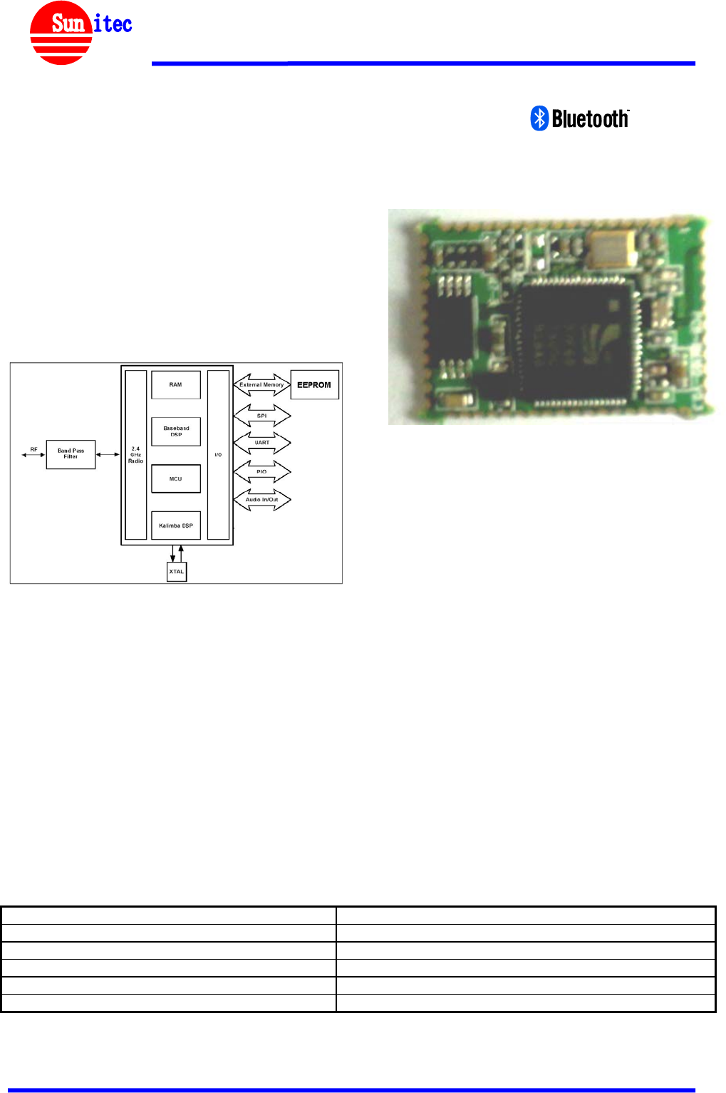
System Architecture
BM160 Class 2 Multimedia Module
CSR, BC57F687A05
Feb. 2012
Product Description:
The BM160 is base on BlueCore5-Multimedia ROM QFN chipset from
leading Bluetooth chipset supplier Cambridge Silicon Radio.
BM160 interfaces a Bluetooth radio, baseband, DSP, high-quality audio
codec, SMPS, LDOs, a battery charger and external EEPROM memory.
BlueTunes ROM QFN uses advanced DSP features for the latest stereo
enhancements and to improve audio quality; including SBC and MP3
decoder, support for FastStream(low battery codec) and 5-band EQ.
The module and device firmware is fully compliant with the Bluetooth
specification v2.1+EDR
Applications:
• Hands-free Car Kit
• Stereo Headset
• AV Headphones
• Echo Cancellation
• High Performance Mono Headsets
• Wireless Speakers
Specifications:
Operating Frequency Band 2.4GHz ~ 2.48GHz unlicensed ISM band
Bluetooth Specification V2.1+EDR
Output Power Class Class 2
Operating Voltage 1.8V or 3.3V
Audio Interface Analogue
Dimension 21mm (L) x 13.5 (W) mm x 2.35mm (H)
Specifications are subject to change without prior notice
Product Specification
Spec-BM160-V1.3 Page 2 of 7 www.sunitec.com.tw
®
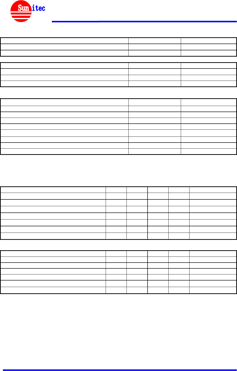
Electrical Characteristics
Absolute Maximum Rating Min Max
Storage Temperature -40°C +85°C
Supply Voltage, (V_CHG) -0.30V +6.5V
Recommended Operating Conditions Min Max
Operating Temperature Range -20°C +70°C
Supply Voltage, (V_BAT) 2.7V 4.2V
Supply Voltage, (V_CHG) 4.5V 6.0V
Power Consumption Units Average
SCO Connection HV3 (30ms interval sniff mode) mA TBD
SCO Connection HV1 mA TBD
ACL Data Transfer 115.2Kbps UART no traffic (Master) mA TBD
ACL Data Transfer 115.2Kbps UART no traffic (Slave) mA TBD
CODEC
Microphone inputs and ADC/channel mA TBD
DAC and loudspeaker driver, no signal/channel mA TBD
Digital audio processing subsystem mA TBD
VBAT = 4.2V; f = 2.441GHz; T=20°C
RF Characteristics
Receiver Units Min Typ Max Bluetooth Spec
Sensitivity at 0.1% BER dBm - -90 -86 ≤-70
Maximum Receiver Signal dBm -20 -10 - ≥ -20
C/I Co-Channel dB - 6 11 ≤11
Adjacent Channel Selectivity C/I -1MHz dB - -6 0 ≤0
2nd Adjacent Channel Selectivity C/I -2MHz dB - -38 -30 ≤-30
3rd Adjacent Channel Selectivity C/I -3MHz dB - -45 -40 ≤-40
Image Rejection C/I dB - -16 -9 ≤-9
VBAT = 4.2V; f = 2.4441GHz; T=20°C
Transmitter Units Min Typ Max Bluetooth Spec
RF Output Power dBm 0 3 - -6 to +4
RF Power Control Range dB 16 24 - > 16
RF Power Range Control Resolution dB - 0.5 - -
20dB Bandwidth for Modulated Carrier KHz - 940 1000 <1000
2nd Adjacent Channel Power (+/- 2MHz) dBm - -36 -20 ≤-20
3rd Adjacent Channel Power (+/- 3MHz) dBm - -45 -40 ≤-40
VBAT = 4.2V; f = 2.4441GHz; T=20°C
All specifications including pinouts and electrical specifications may be changed without prior notice

Product Specification
Spec-BM160-V1.3 Page 3 of 7 www.sunitec.com.tw
®
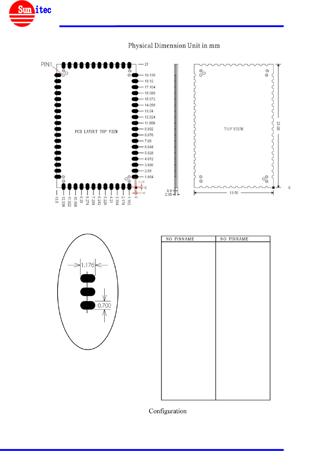
Pin Configurations
PIN NO. NAME TYPE FUNCTION RE-MARK
1 AIO1 Bi-directional Programmable input/output line
2 AIO0 Bi-directional Programmable input/output line
3 RESET CMOS input with
weak internal pull-up Reset if low. Input debounced so must be low for >5ms to
cause a reset
4 GND GND Ground
5 PIO9 Bi-directional Programmable Input/Output Line
6 N/A
7 PIO11 Bi-directional Programmable Input/Output Line
8 PIO12 Bi-directional Programmable Input/Output Line
9 PIO13 Bi-directional Programmable Input/Output Line
10 PIO14 Bi-directional Programmable Input/Output Line
11 N/A
12 GND GND Ground
13 VDD Power 3.3V Supply For 3.3V Version
VDD Power Connect to 1V8 For 1.8V Version
14 VDD_USB Power Positive Supply For UART/USB Port Connect to VDD
15 +1V8 Power +1.8V Supply
16 GND GND Ground
17 N/A
18 N/A
19 UART_RTS CMOS Output UART Request To Send (Active Low)
20 UART_CTS CMOS Input UART Clear To Send (Active Low)
21 UART_RX CMOS Input UART Data Input (Active High)
22 UART_TX CMOS Output UART Data Output (Active High)
23 N/A
24 N/A
25 TEST_EN For test purposes only, Leave unconnected
26 N/A
27 SPI_CSB CMOS Input Chip Select For Synchronous Serial Interface (Active Low)
28 SPI_MISO CMOS Output Serial Peripheral Interface Data Output
29 SPI_CLK CMOS Input Serial Peripheral Interface Data Clock
30 SPI_MOSI CMOS Output Serial Peripheral Interface Data Input
31 VRE_IN Analogue Take high to enable switch-mode regulator
32 VDD_BAT Battery terminal +ve Lithium ion/polymer battery positive terminal. Battery
charger output and input to switch-mode regulator
33 GND GND Ground
34 VDD_CHG Charger input Lithium ion/polymer battery charger input
35 LED1 Open drain output LED Driver
36 LED0 Open drain output LED Driver
37 GND GND Ground
38 SPK_L_N Analogue Speaker output negative, left
39 SPK_L_P Analogue Speaker output positive, left
40 SPK_R_N Analogue Speaker output negative, right
41 SPK_R_P Analogue Speaker output positive, right
42 GND_S Analogue GND Analogue Ground
43 MIC_BIAS Analogue Microphone bias
44 MIC_B_P Analogue Microphone input positive, right
45 MIC_B_N Analogue Microphone input negative, right
46 MIC_A_P Analogue Microphone input positive, left
47 MIC_A_N Analogue Microphone input negative, left
48 GND GND Ground
49 PIO0 Bi-directional Programmable Input/Output Line
50 PIO1 Bi-directional Programmable Input/Output Line
51 PIO2 Bi-directional Programmable Input/Output Line
52 PIO3 Bi-directional Programmable Input/Output Line
53 PIO4 Bi-directional Programmable Input/Output Line
54 PIO5 Bi-directional Programmable Input/Output Line
55 PIO6 Bi-directional Programmable Input/Output Line
56 PIO7 Bi-directional Programmable Input/Output Line
57 PIO8 Bi-directional Programmable Input/Output Line
58 GND GND Ground
59 RF-IN RF RF Interface
60 GND GND Ground
Product Specification
Spec-BM160-V1.3 Page 4 of 7 www.sunitec.com.tw
®
Recommended Layout patterns:
11 NC
6 NC
13 NC
14 NC
15 +1V8
16 GND
17 NC
18 NC
1.AIO1
2.AIO0
3.RESET
4.GND
5.PIO9
6.N/A
7.PIO11
8.PIO12
9.PIO13
10.PIO14
11.N/A
12.GND
13.VDD
14.VDD_USB
15.+1V8
16.GND
17.N/A
18.N/A
19.UART_RTS
20.UART_CTS
21.UART_RX
22.UART_TX
23.N/A
24.N/A
25.TEST_EN
26.N/A
27.SPI_CSB
28.SPI_MISO
29.SPI_CLK
30.SPI_MOSI
31.VRE_IN
32.VDD_BAT
33.GND
34.VDD_CHG
35.LED1
36.LED0
37.GND
38.SPK_L_N
39.SPK_L_P
40.SPK_R_N
41.SPK_R_P
42.GND_S
43.MIC_BIAS
44.MIC_B_P
45.MIC_B_N
46.MIC_A_P
47.MIC_A_N
48.GND
49.PIO0
50.PIO1
51.PIO2
52.PIO3
53.PIO4
54.PIO5
55.PIO6
56.PIO7
57.PIO8
58.GND
59.RF
60 GND
Product Specification
Spec-BM160-V1.3 Page 5 of 7 www.sunitec.com.tw
®
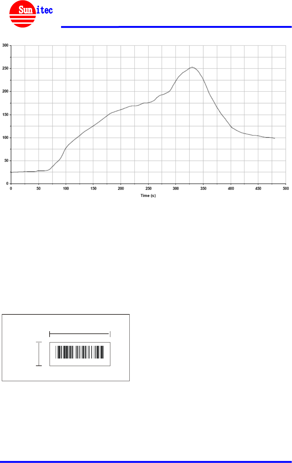
Recommended Reflow Temperature Profile:
Key features of the profile:
-Initial Ramp=1-2.5℃/sec to 175℃ equilibrium
-Equilibrium time=60 to 80 seconds
-Ramp to Maximum temperature (250℃)=3℃/sec Max
-Time above liquidus temperature(217℃): 45 - 90 seconds
-Device absolute maximum reflow temperature: 250℃
MAC Address:
Each Module has his MAC Address
001d df XXXXXX
Concerning the dimension of the tab,only printing the last six letters of the LAP on the module.
xxxxxx
5.0 mm
13.0 mm
The tab code pastes style:
Product Specification
Spec-BM160-V1.3 Page 6 of 7 www.sunitec.com.tw
®
QDL Certificate
Product Specification
Spec-BM160-V1.3 Page 7 of 7 www.sunitec.com.tw
®
Ordering Information
No Items Ordering Code (Class 2) Description
2 BlueTunes Module BM160
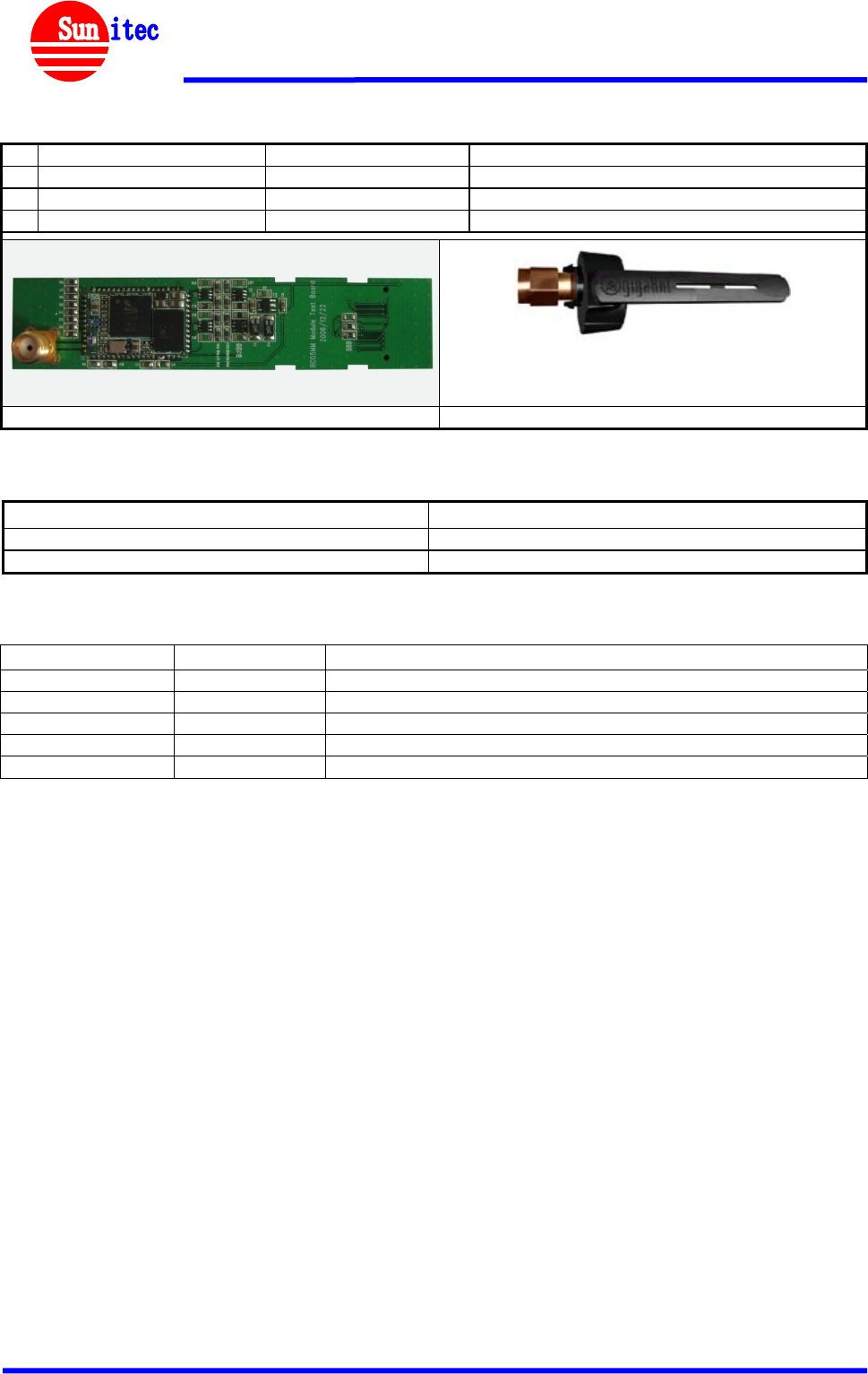
3 BlueTunes Module Test Kit BM160 TK Test kit to fit CSR Casira Kit
4 Titan is Antenna 2010B4844-01 GigaAnt 2.4GHz Swivel SMA Antenna
BM160S Test Kit Titanis Antenna
Document References
References Version
Specifications of the Bluetooth System V2.1+EDR, 26 July 2007
BlueTunes ROM QFN Data Sheet CS-122312-DSP1 23 Oct 2008
Document History
Revision Date History
Draft V0.1 2009-10-22
V1.0 2009-11-30 Official release
V1.1 2009-12-01
V1.2 2009-12-02 Swap LED0 and LED1
V1.3 2012-02-20 Add BQB Certificate
Contact Information
Sunitec Enterprise Co., Ltd.
Head Office:
3F.,No.98-1,Mincyuan Rd Sindian City, Taipei
County 231,Taiwan
Tel: 886-2-82191696
Fax: 886-2-82191676
China Factory:
No.2,Qilin Road 2,Run Tang Ind., Dan-Keng Village Fu
Ming Community, Guan-lan Town, BaoAn District,
Shenzhen GuangDong China
Tel: 86-755-29802983
Fax: 86-755-29802984
E-mail:sales@sunitec-cn.com & project@sunitec-cn.com
http://www.sunitec-cn.com

Notice: The user should not modify or change this equipment without written
approval form SANGEAN ELECTRONICS INC. Modification could void
authority to use this equipment.
Label for end product must include “Contains FCC ID: BYG024” or “A RF
transmitter inside, FCC ID: BYG024”.
FCC ID Label Graph:
FCC ID: BYG024
Model: BM160-CB1-SJ
This device complies with Part 15 of the FCC Rules. Operation is subject to the
following two conditions: (1) this device may not cause harmful interference,
and (2) this device must accept any interference received, including
interference that may cause undesired operation.
Note:
If the product is too small to make so many text labels, only need to indicate
the FCC ID number on the label, but the above text will be printed in the
manual or packaging box.
IMPORTANT NOTE: To comply with the FCC RF exposure compliance
requirements, the antenna(s) used for this transmitter must be installed to
provide a separation distance of at least 20 cm from all persons and must not
be co-located or operating in conjunction with any other antenna or transmitter.
No change to the antenna or the device is permitted. Any change to the
antenna or the device could result in the device exceeding the RF exposure
requirements and void user’s authority to operate the device.
The module has been regulatory approved for integrations which meet the
following conditions:
1. The radio integration is embedded
2. The antenna must be installed such that 20 cm is maintained between the
antenna and users
3. The ‘Type’ and ‘Gain’ of the antenna selected for the integration of the
external antenna must meet the requirements as detailed in section.
Used outside of these conditions will trigger re-approval.