Sanwa Electronic Instrument Co 90408 6CH 2.4GHz Radio Control Systems User Manual Manual Part 2
Sanwa Electronic Instrument Co Ltd 6CH 2.4GHz Radio Control Systems Manual Part 2
UserManual.wiki
>
Sanwa Electronic Instrument Co
>
90408 User Manual
>
Manual Part 2
Contents
1.
Manual Part 1
2.
Manual Part 2
Manual Part 2
Navigation menu
Upload a User Manual
Namespaces
Wiki Guide
HTML
PDF
Info
Views
User Manual
Discussion / Help
Navigation
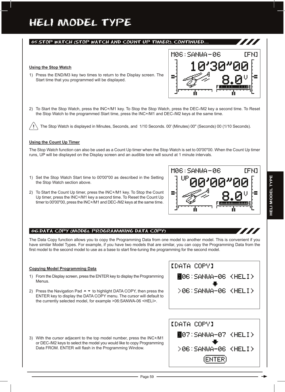
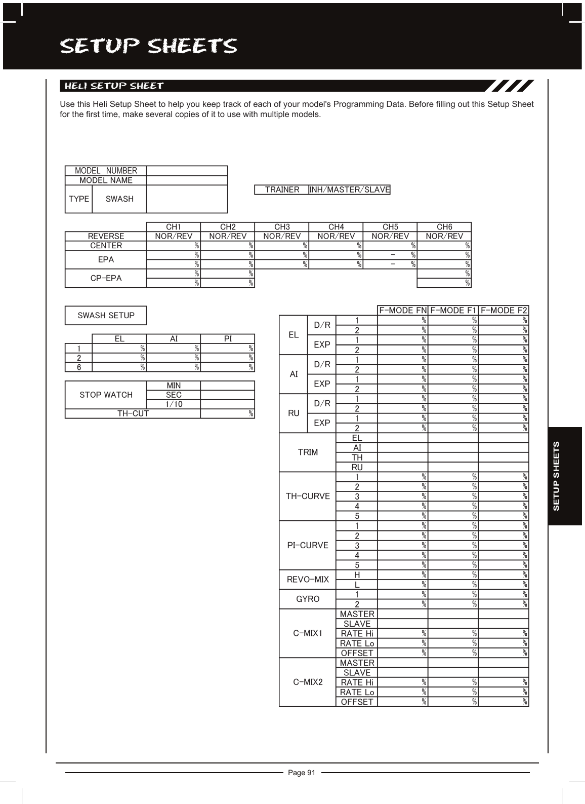
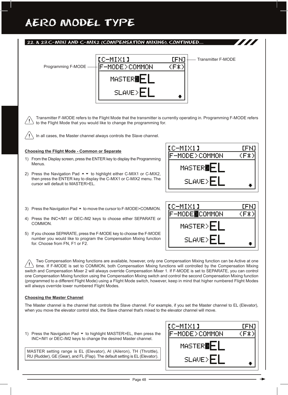
![Page 22aERO MODEL TyPEaERO MODEL TyPE PROgRaMMing MEnU FLOw chaRTUse this Flow Chart to familiarize yourself with the AERO Model Type Programming Menu structure. Descriptions regarding all AERO Model Type functions and programming are found on pages 23 through 50.04.TRAINER03.TYPE02.MODEL NAME01.MODEL SELE05.STOP WATCH06.DATA COPY07.DATA RESET08.REVERSE09.CENTER10.EPA11.TH-CUT12.D/R & EXP13.TRIM14.TH-CURVE15.AI-DIFF16.FLAPERON17.FL>EL18.DUAL EL19.AILVATOR20.V-TAIL21.DELTA22.C-MIX1666666666666666666666AERO HELI6623.C-MIX224.SX MONITOR66To access the AERO Model Type Programming Menus, turn the transmitter ON. From the Display screen, press the ENTER key to display the Programming Menus, then press the Navigation Pad 56to scroll to the desired Programming Menu. Press the ENTER key to access the desired Programming Menu.From within any Programming Menu, press the END/M3 key continuously to return to the Display screen. Unless otherwise noted, all programming changes take effect immediately.If the Display screen is not displayed when you turn the transmitter ON, continuously press the END/M3 key until the Display screen is displayed.gEnERaL inFORMaTiOnINH MASTER66SLAVE6NOR REV66MIN SEC661/106D/R [1] - D/R [2] EXP [1] - EXP [2]66COMMON SEPARATE66HOLD POINT66RATE6MASTER SLAVE66RATE HIGH / RATE LOW6OFFSET6MASTER SLAVE66RATE HIGH / RATE LOW6OFFSET6ELEVATOR (DOWN) ELEVATOR (UP)66AILERON (LEFT)6AILERON (RIGHT)6ELEVATOR (DOWN) ELEVATOR (UP)66RUDDER (LEFT)6RUDDER (RIGHT)6Some Programming Menus cannot be accessed unless certain Model Type selection options are chosen rst. For example, you cannot access the AI-DIFF menu unless you have chosen AILE>2 in the TYPE menu.TH-TRIM LOCK (F1)6](https://usermanual.wiki/Sanwa-Electronic-Instrument-Co/90408.Manual-Part-2/User-Guide-2077419-Page-21.png)


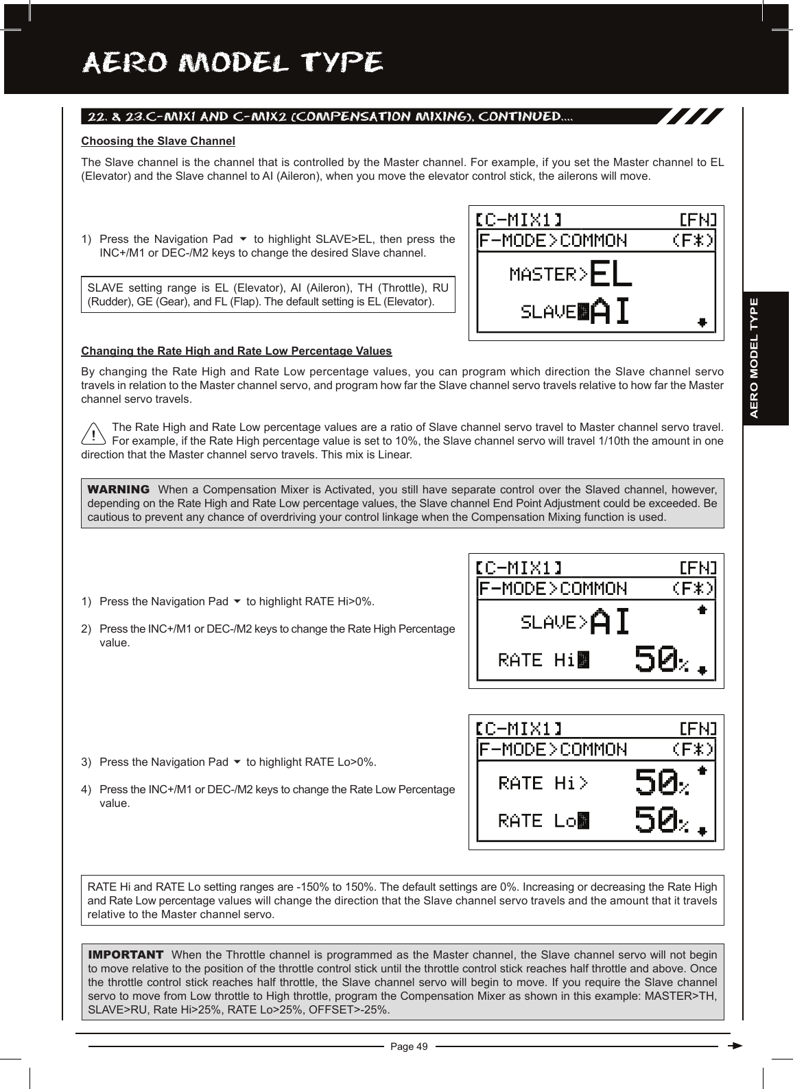
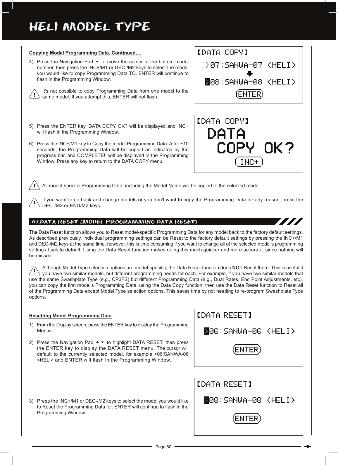
![Page 52hELi MODEL TyPEhELi MODEL TyPE PROgRaMMing MEnU FLOw chaRTUse this Flow Chart to familiarize yourself with the HELI Model Type Programming Menu structure. Descriptions regarding all HELI Model Type functions and programming are found on pages 53 through 80.04.TRAINER03.TYPE02.MODEL NAME01.MODEL SELE05.STOP WATCH06.DATA COPY07.DATA RESET08.REVERSE09.CENTER10.EPA6666666666HELI AERO66To access the HELI Model Type Programming Menus, turn the transmitter ON. A helicopter icon will be shown on the Display screen. From the Display screen, press the ENTER key to display the Programming Menus, then press the Navigation Pad 56to scroll to the desired Programming Menu. Press the ENTER key to access the desired Programming Menu.gEnERaL inFORMaTiOnFrom within any Programming Menu, press the END/M3 key continuously to return to the Display screen. If the Display screen is not displayed when you turn the transmitter ON, continuously press the END/M3 key until the Display screen is displayed.If a helicopter icon is not shown on the Display screen, use the Model Select function to select a HELI model. For more information, see page 53.INH MASTER66SLAVE6NOR REV66MIN SEC661/10611.CP-EPA12.SWASH6613.TH-CUT14.D/R & EXP15.TRIM16.TH-CURVE17.PI-CURVE18.REVO-MIX19.GYRO20.C-MIX121.C-MIX222.SX MONITOR666666666D/R [1] - D/R [2] EXP [1] - EXP [2]66COMMON SEPARATE66HOLD POINT66POINT RATE66HIGH LOW66GYRO [1] GYRO [2]66MASTER SLAVE66RATE HIGH / RATE LOW6OFFSET6MASTER SLAVE66RATE HIGH / RATE LOW6OFFSET6TH-TRIM LOCK (F1)6Unless otherwise noted, all programming changes take effect immediately.](https://usermanual.wiki/Sanwa-Electronic-Instrument-Co/90408.Manual-Part-2/User-Guide-2077419-Page-51.png)