Sanwa Electronic Instrument Co 90478 Digital High Response Telemetry System User Manual MT 4S User s Guide indd
Sanwa Electronic Instrument Co Ltd Digital High Response Telemetry System MT 4S User s Guide indd
Contents
- 1. User Manual-1
- 2. User Manual-2
User Manual-1
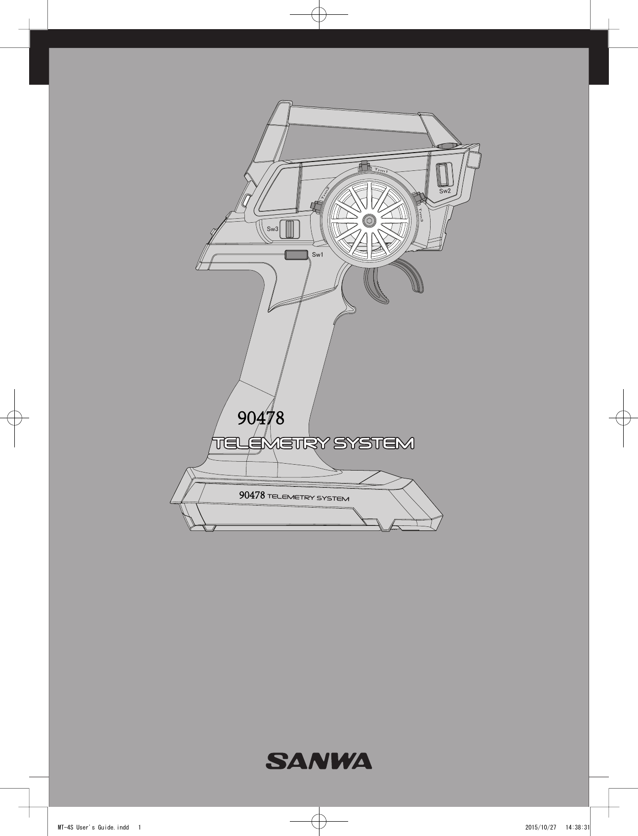
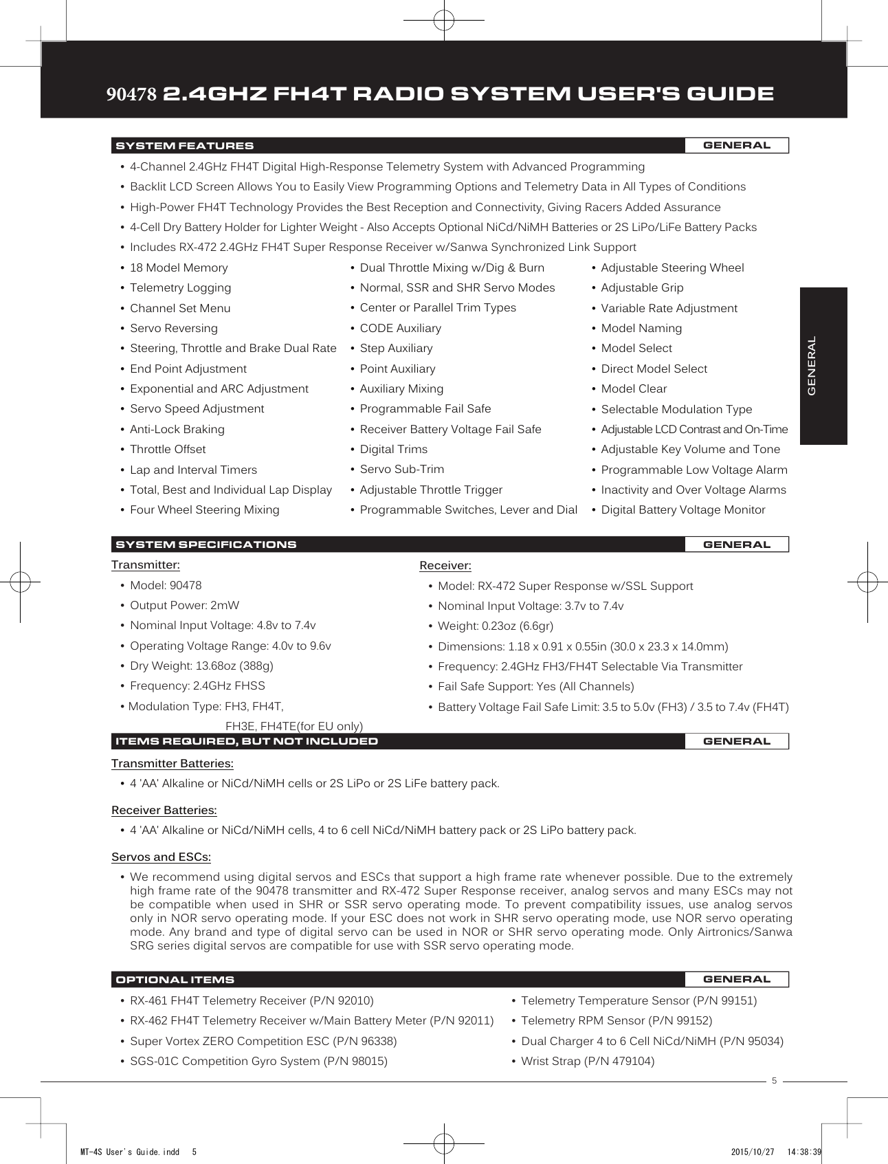
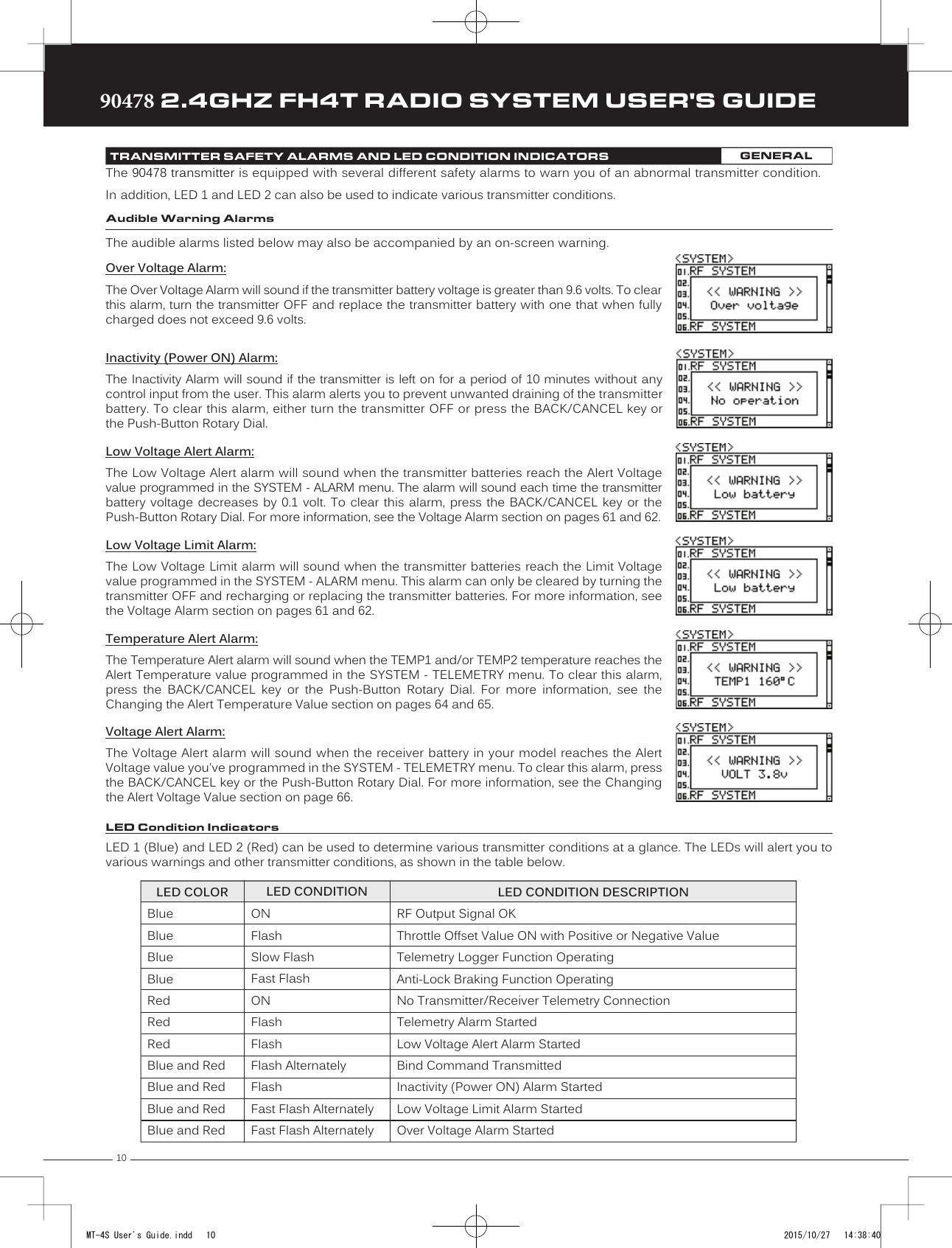
![1690478 2.4GHZ FH4T RADIO SYSTEM USER'S GUIDETRTRTRThe Binding function allows you to Bind the transmitter and receiver pair. When new, it is necessary to pair the transmitter and receiver to prevent interference from transmitters operated by other users. This operation is referred to as Binding. Once the Binding process is complete, the setting is remembered even when the transmitter and receiver are turned OFF. Therefore, this procedure usually only needs to be done once.Under some circumstances, the receiver may not operate after turning the transmitter and receiver ON. If this occurs, perform the Binding process again.Before beginning the Binding process, connect your servos and receiver battery pack to the receiver. For more information, see the Receiver Connections and Mounting section on page 8. The transmitter and the receiver should be turned OFF.4) While holding down the Bind Button on the receiver,turn the receiver ON. The Bind LED on the receiver willflash slowly. After approximately 2 seconds, release theBind Button. The Bind LED on the receiver will continue toflash slowly.Transmitter and Receiver Binding:1) Turn the transmitter ON. The Top Screen will be displayed. Press the ENTER key (Push-Button Rotary Dial) to open theProgramming Menu list, then scroll UP or DOWN to highlight the SYSTEM menu.5) Press the ENTER key. The [ENTER] command will begin to flash and the Bind LED onthe receiver will flash rapidly, then go out.6) After the Bind LED on the receiver goes out, press the ENTER key a second time. The Bind LED on the receiver will illuminatesolid blue and LED 2 on the transmitter will go out, indicating that the Binding procedure is complete and a Telemetryconnection has been made.Verify that the Modulation is set to [RF MODE]:FH4T is displayed an that the Servo Operating Mode for each channel is set to NOR. If it isn't, change the Modulation Type to FH4T. If you need to change any of these settings, see the BIND Menu section on pages 52 and 53.3) Scroll UP or DOWN to highlight the [ENTER] command. Do not press the ENTER key yet.7) Move the steering wheel and throttle trigger to verify that the servos are operating normally, then press and HOLD theBACK/CANCEL key to return to the Top Screen.When the Binding procedure is successful, the Bind LED on the receiver and LED 1 on the transmitter will illuminate solid blue. If the Bind LED on the receiver is flashing rapidly or is not illuminated at all, the transmitter and receiver are not paired. In this case, turn both the transmitter and receiver OFF, then repeat the Binding procedure again.BINDING THE TRANSMITTER AND RECEIVER GENERALIMPORTANT: This section details Binding the RX-472 4-Channel 2.4GHz FH4T Super Response receiver with the Servo Operating Mode set to Normal mode. If you are Binding an FH2 or FH3 receiver, or if you prefer to change the Servo Operating Mode, see the BIND Menu section on pages 52 and 53.2) Press the ENTER key to open the SYSTEM menu, then scroll DOWN to highlight theBIND menu. Press the ENTER key to open the BIND menu.You must complete step 5 below within 10 seconds or the Bind LED will go out, indicating the receiver has timed out. If this occurs, turn the receiver OFF, then repeat step 4.MT-4S User's Guide.indd 16 2015/10/27 14:38:50](https://usermanual.wiki/Sanwa-Electronic-Instrument-Co/90478.User-Manual-1/User-Guide-2816265-Page-15.png)
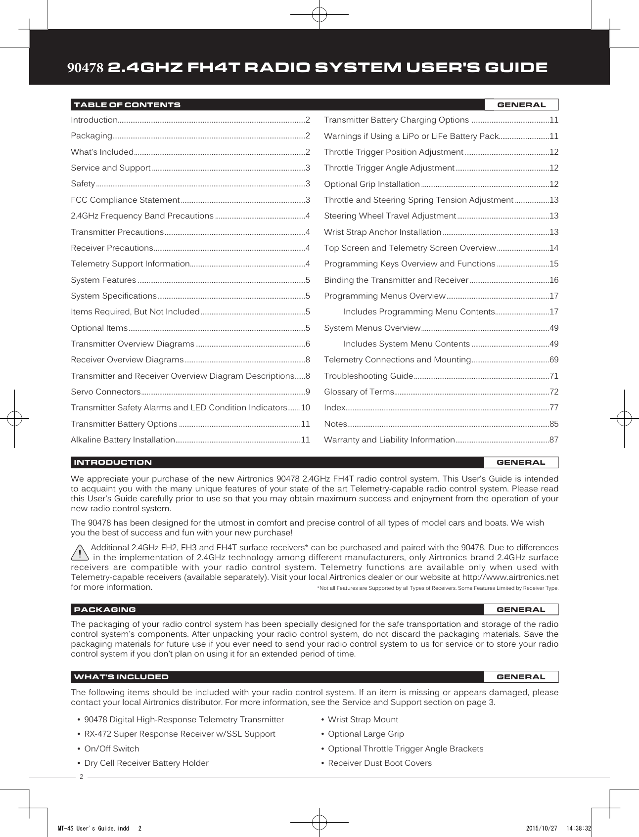
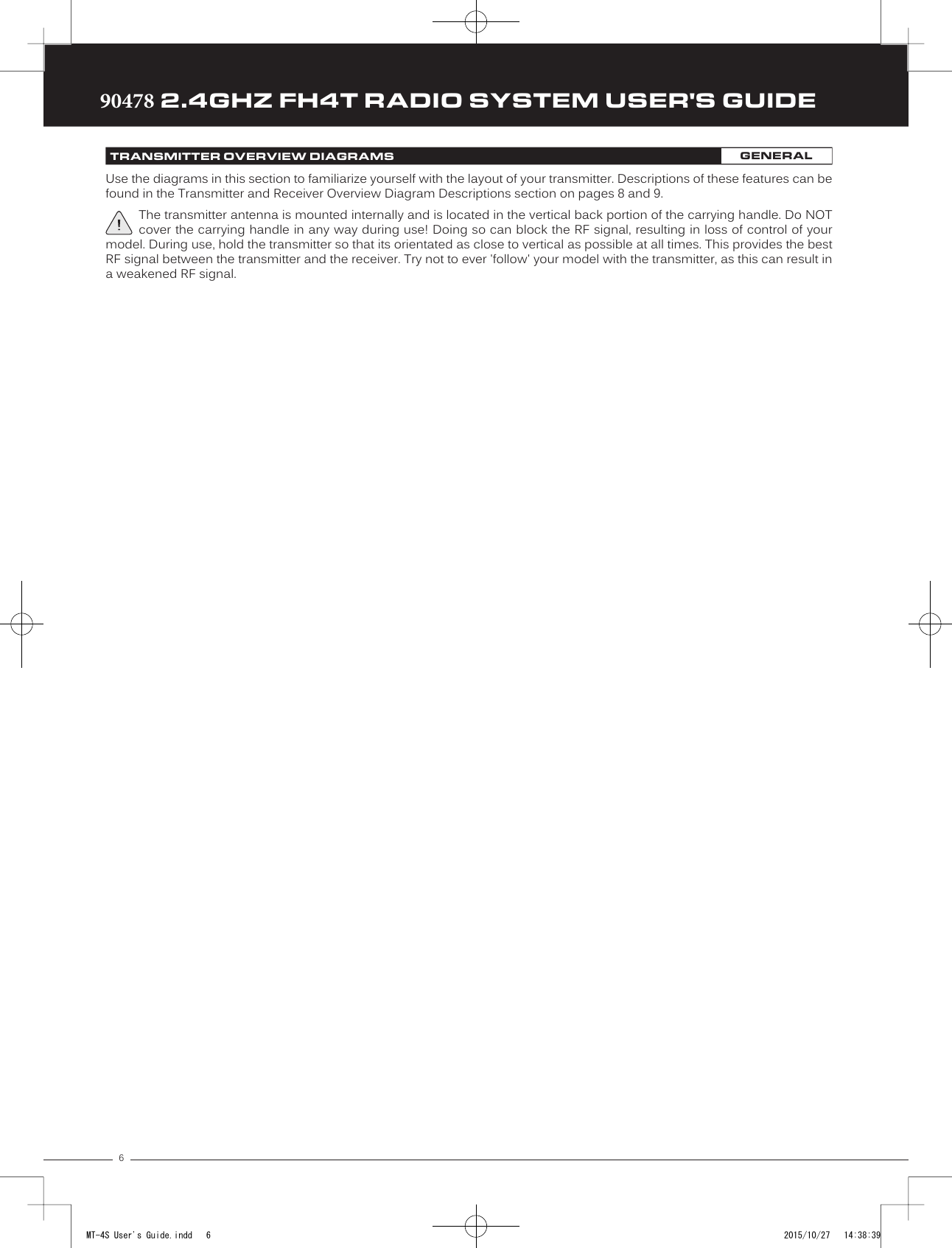
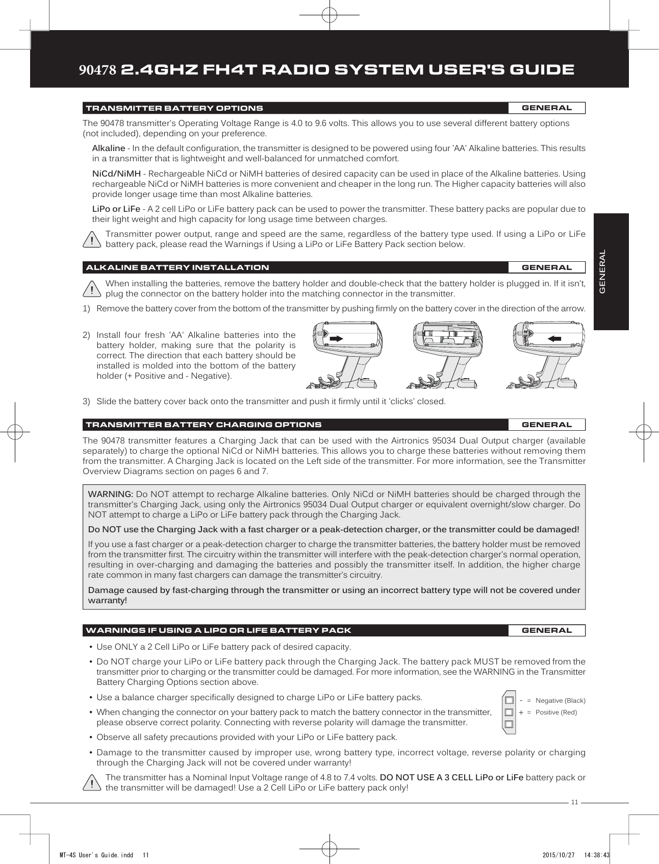
![17TRTRTR90478 2.4GHZ FH4T RADIO SYSTEM USER'S GUIDEPG. 17PG. 18PG. 19PG. 21PG. 23PG. 24PG. 26PG. 27PG. 34PG. 41PG. 42PG. 43PG. 46PG. 46PG. 47PG. 49The Channel Set function allows you to make programming changes to each of the four channels without the need to enter each Programming Menu separately. It encompasses the most common programming options in one convenient location. For example, you can make all of your desired programming changes, such as End Point Adjustment, Exponential, Servo Speed, Fail Safe settings, etc., for each channel, all from within the same menu.PROGRAMMING MENUS OVERVIEWThe Programming Menus allow you to program the various functions of the 90478 trans-mitter, in addition to being able to access the System Menu. 1) To access the various Programming Menus, turn the transmitter ON, then press theENTER key (Push-Button Rotary Dial). A list of Programming Menus will be displayedalong the right side of the screen and the last Programming Menu when the transmitterwas turned OFF will be highlighted. The currently highlighted Programming Menu willbe displayed in the background.1) From the Top Screen, press the ENTER key to open the Programming Menu list.2) Scroll UP or DOWN to highlight the CH-SET menu, then press the ENTER key. The CH-SETmenu will be displayed and the cursor will default to [ST].01.CH-SET02.D/R03.EPA04.CURVE05.SPEED06.ALB07.OFFSET08.AUX109.AUX210.TRIM11.REV12.TIMER13.LAP14.F/S15.LOGGER16.SYSTEMChannel SetDual RateEnd Point AdjustmentCurveServo SpeedAnti-Lock BrakingThrottle OffsetAuxiliary 1Auxiliary 2Servo TrimServo ReversingLap and Interval TimersLap TimesFail SafeTelemetry LoggingSystem MenuChange Common Programming Options From One LocationAdjust Channel Dual RatesAdjust Channel End PointsAdjust Channel Exponential or Adjustable Rate Control (ARC)Slow Down Servo Speed in Both DirectionsProgram the Anti-Lock Braking FunctionProgram the Throttle Offset PositionAdjust Auxiliary 1 Channel 3 Functions and ProgrammingAdjust Auxiliary 2 Channel 4 Functions and ProgrammingAdjust Servo Trim and Servo Sub-TrimChange the Direction that the Servos TravelProgram the Lap Timer and the Interval TimerDisplays Current, Past and Best Lap TimesProgram Fail Safe SettingsView Logs of Temperature, Voltage and RPM Telemetry DataAccess the System MenuMENU MENU NAME MENU DESCRIPTIONPROGRAMMING MENUSPAGE3) Scroll DOWN to move the cursor to the channel you would like to make ProgrammingValue changes to. Choose from <CH-SET> [ST] (Steering), <CH-SET> [TH] (Throttle),<CH-SET> [A1] (Auxiliary 1) or <CH-SET> [A2] (Auxiliary 2).PROGRAMPROGRAM01.CH-SET (CHANNEL SET)PROGRAM2) Use the Push-Button Rotary Dial to scroll UP or DOWN to highlight the desired Programming Menu, then press the ENTER keyto open the highlighted Programming Menu.PRO TIP: Most Programming Menus feature a Servo Monitor at the bottom of the screen that you can use to see your programming changes in virtual real time.MT-4S User's Guide.indd 17 2015/10/27 14:38:50](https://usermanual.wiki/Sanwa-Electronic-Instrument-Co/90478.User-Manual-1/User-Guide-2816265-Page-16.png)
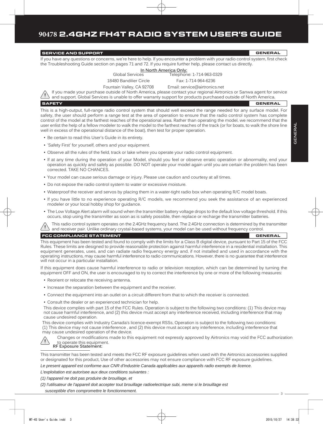
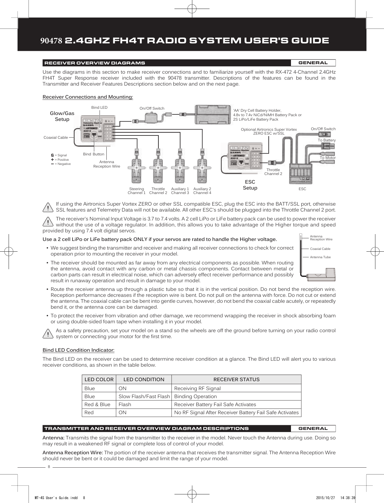
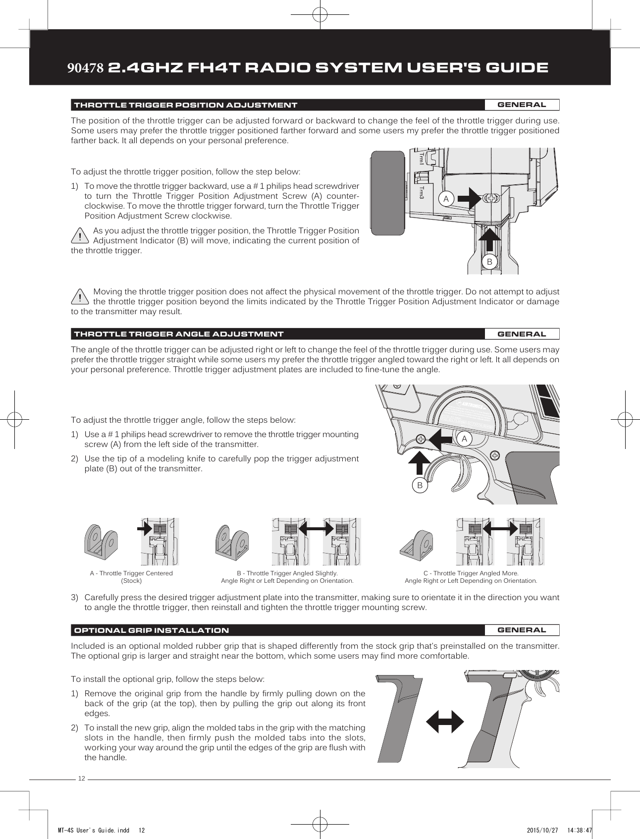
![1890478 2.4GHZ FH4T RADIO SYSTEM USER'S GUIDETRTRTR6) After changing the desired Programming Value, press the ENTER key or the BACK/CANCEL key and the highlighted optionwill stop flashing, indicating you can scroll UP or DOWN to highlight another programming option.7) To change to another channel, press the BACK/CANCEL key, then scroll UP or DOWN to select the desired channel. Repeatsteps 4 and 5 above to change the desired Programming Values for that channel.8) When complete, press and HOLD the BACK/CANCEL key to return to the Top Screen.01.D/R - RATE02.EPA - L/R03.EPA - LEFT04.EPA - RIGHT05.CURVE - RATE06.CURVE - POINT07.SPEED - FORWARD08.SPEED - RETURN09.TRIM10.SUB-T11.REV - NOR/REV12.F/S01.D/R - TH02.D/R - BR03.EPA - HIGH04.EPA - LOW05.CURVE - RATE-H06.CURVE - POINT-H07.CURVE - RATE-B08.CURVE - RATE-H09.SPEED - FORWARD10.SPEED - RETURN11.ALB - POINT12.ALB - STROKE13.ALB - LAG14.ALB - RELEASE15.ALB - HOLD16.TRIM17.SUB-T18.REV - NOR/REV19.F/S01.EPA - HIGH02.EPA - LOW03.CURVE - RATE04.CURVE - POINT05.CURVE06.CURVE07.SPEED - FORWARD08.SPEED - RETURN09.TRIM10.SUB-T11.REV - NOR/REV12.F/S01.EPA - HIGH02.EPA - LOW03.CURVE - RATE04.CURVE - POINT05.CURVE06.CURVE07.SPEED - FORWARD08.SPEED - RETURN09.TRIM10.SUB-T11.REV - NOR/REV12.F/S[ST] STEERING [TH] THROTTLE [A1] AUXILIARY 1 [A1] AUXILIARY 2The Dual Rate function allows you to change the control authority of the Steering, Throttle High Side and Throttle Brake Side by changing the amount of servo travel relative to control input. For example, by increasing the Steering Dual Rate, you can make the steering servo travel more, which might prevent your model from pushing during turns. If your model oversteers during turns, you can reduce the amount of Steering Dual Rate. Adjusting Steering Dual Rate affects both Right-hand and Left-hand steering equally, however, you are able to adjust Throttle Dual Rate on the Throttle High Side and Throttle Brake Side independently.IMPORTANT: Prior to programming the Dual Rate function, you should adjust the maximum Left and Right (or High and Low) End Points, using the End Point Adjustment function. For more information, see the End Point Adjustment section on pages 19 through 21.01.CH-SET (CHANNEL SET)PROGRAM02.D /R (DUAL RATE)PROGRAM4) Press the ENTER key to highlight the Programming Value in the upper right corner.5) Scroll UP or DOWN to highlight the Programming Value you would like to change, thenpress the ENTER key to select it. The highlighted Programming Value will flashindicating you can change the Programming Value. Scroll UP or DOWN to change theProgramming ValueThe following functions can be programmed from within the Channel Set menu:Dual Rate is a percentage of End Point Adjustment. For example, if you set the Steering Dual Rate percentage value to 100%, the Steering will travel the same amount defined by your End Point Adjustment programming. Alternately, if you set the Steering Dual Rate percentage value to 50%, the Steering will travel half the amount defined by your End Point Adjustment programming.MT-4S User's Guide.indd 18 2015/10/27 14:38:50](https://usermanual.wiki/Sanwa-Electronic-Instrument-Co/90478.User-Manual-1/User-Guide-2816265-Page-17.png)
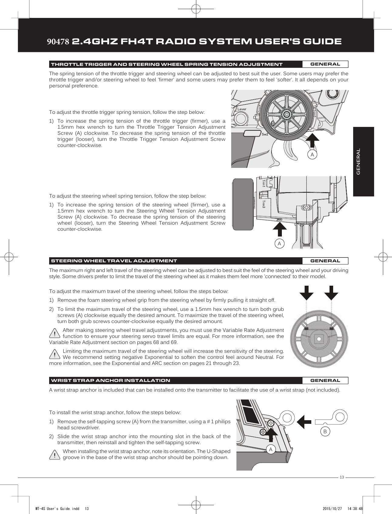
![19TRTRTR90478 2.4GHZ FH4T RADIO SYSTEM USER'S GUIDEAdjusting the Throttle Dual Rate Percentage Value:1) From within the D/R menu, scroll UP or DOWN to highlight [TH]:RATE 100%.2) Press the ENTER key, then scroll UP or DOWN to increase or decrease the ThrottleDual Rate percentage value. When the Throttle Dual Rate percentage value is decreased,Throttle High side servo travel is decreased. When the Throttle Dual Rate percentagevalue is increased, Throttle High side servo travel is increased.D/R TH RATE setting range is 0% to 100%. The default setting is 100%.Adjusting the Brake Dual Rate Percentage Value:1) From within the D/R menu, scroll UP or DOWN to highlight [BR]:RATE 100%.2) Press the ENTER key, then scroll UP or DOWN to increase or decrease the Brake DualRate percentage value. When the Brake Dual Rate percentage value is decreased, ThrottleBrake side servo travel is decreased. When the Brake Dual Rate percentage value isincreased, Throttle Brake side servo travel is increased.D/R BR RATE setting range is 0% to 100%. The default setting is 100%.Trm3 [ST]Trm4 [TH]Controlling the Dual Rate Function:1) By assigning the Steering, Throttle and Brake Dual Rate programming functions toone or more of the Trim Switches, Auxiliary Lever or Dial Knob, these functions canbe adjusted while driving without accessing the Programming Menu. In addition,these functions can be toggled OFF and ON by assigning them to one or morePush-Button Switches. For more information, see the Key Assignments section onpages 53 through 58.In the default configuration, the Steering and Throttle Dual Rate programming functions are adjusted using Trim Switch Trm3 and Trim Switch Trm4, respectively.D/R ST RATE setting range is 0% to 100%. The default setting is 100%.3) Press the ENTER key, then scroll UP or DOWN to increase or decrease the SteeringDual Rate percentage value. When the Steering Dual Rate percentage value is decreased,steering servo travel is decreased. When the Steering Dual Rate percentage value isincreased, steering servo travel is increased.02.D /R (DUAL RATE)PROGRAMAdjusting the Steering Dual Rate Percentage Value:1) From the Top Screen, press the ENTER key to open the Programming Menu list.2) Scroll UP or DOWN to highlight the D/R menu, then press the ENTER key. The D/R menuwill be displayed and [ST]:RATE 100% will be highlighted.PROGRAMThe End Point Adjustment function allows you to adjust servo travel in each direction. This makes it possible to balance servo travel in both directions and set the maximum desired amount of servo travel. For example, on a gas-powered model, if you pull the throttle trigger and the carburetor does not open completely, you can increase the Throttle High End Point Adjustment so that the carburetor opens completely. Another example is with steering. If your model turns sharper to the right than to the left, you can increase the Steering Left End Point Adjustment to balance the steering. The End Point Adjustment function can be adjusted for the Steering channel (Right and Left), the Throttle channel (Throttle High Side and Throttle Brake Side), Auxiliary 1 Channel 3 (High and Low) and Auxiliary 2 Channel 4 (High and Low). 03.EPA (END POINT ADJUSTMENT)PROGRAMMT-4S User's Guide.indd 19 2015/10/27 14:38:51](https://usermanual.wiki/Sanwa-Electronic-Instrument-Co/90478.User-Manual-1/User-Guide-2816265-Page-18.png)
![2090478 2.4GHZ FH4T RADIO SYSTEM USER'S GUIDETRTRTRIMPORTANT: Before making End Point Adjustments, the servo horn needs to be centered. Install the servo horn onto the servo, making sure it's as close to being centered as possible, then use the Servo Sub-Trim function to center the servo arm exactly. For more information, see the Adjusting the Servo Sub-Trim Values section on page 41.1) From the Top Screen, press the ENTER key to open the Programming Menu list.2) Scroll UP or DOWN to highlight the EPA menu, then press the ENTER key. The EPAmenu will be displayed and [ST]:EPA L100% will be highlighted.Adjusting the Steering End Point Adjustment Percentage Values:Your model’s turning radius can differ from left to right because of variations in linkage, suspension balance, tire diameter, or weight distribution. In such cases, Left Steering servo travel and Right Steering servo travel are adjustable using the End Point Adjustment function.EPA ST R setting range is 0% to 150%. The default setting is 100%.4) From within the EPA menu, scroll DOWN to highlight [ST]:EPA R100%. Press the ENTERkey, then scroll UP or DOWN to increase or decrease the Steering Right End PointAdjustment percentage value. Increasing the percentage value will increase steeringservo travel in that direction and decreasing the percentage value willdecrease steering servo travel in the direction.3) Press the ENTER key, then scroll UP or DOWN to increase or decrease the Steering LeftEnd Point Adjustment percentage value. Increasing the percentage value will increasesteering servo travel in that direction and decreasing the percentage value will decreasesteering servo travel in the that direction.EPA ST L setting range is 0% to 150%. The default setting is 100%.Adjusting the Throttle End Point Adjustment Percentage Values:Your model's carburetor may not open completely, or it may open too much and cause the throttle servo to bind. If you're using an Electronic Speed Control, the Electronic Speed Control may not command full power, or the brake may not engage adequately. In such cases, Throttle High servo travel and Throttle Brake servo travel are adjustable using the End Point Adjustment function.Steering EPA L/R can be adjusted from within the Channel Set menu. This option changes both Left and Right Steering End Point Adjustment percentage values equally at the same time, which is similar to adjusting Steering Dual Rate.03.EPA (END POINT ADJUSTMENT)PROGRAMEnd Point Adjustment percentage values should not be increased to the point where your linkages and servos Bind when moved all the way to the Right or Left. Binding will cause the servos to 'buzz', resulting in a quicker loss of receiver battery power and eventual damage to the servos or to your Model.1) From within the EPA menu, scroll UP or DOWN to highlight [TH]:EPA H 100%.2) Press the ENTER key, then scroll UP or DOWN to increase or decrease the Throttle HighEnd Point Adjustment percentage value. Increasing the percentage value will increaseThrottle High servo travel in that direction and decreasing the percentagevalue will decrease Throttle High servo travel in that direction.EPA TH H setting range is 0% to 150%. The default setting is 100%.MT-4S User's Guide.indd 20 2015/10/27 14:38:52](https://usermanual.wiki/Sanwa-Electronic-Instrument-Co/90478.User-Manual-1/User-Guide-2816265-Page-19.png)
![21TRTRTR90478 2.4GHZ FH4T RADIO SYSTEM USER'S GUIDEIf you're using an Electronic Speed Control, the Throttle High and the Throttle Brake End Point Adjustment percentage values are both generally set to 100%, although the Throttle High direction may need to be increased to achieve full power. In some cases the End Point Adjustments can also be set directly via the Electronic Speed Control.EPA TH B setting range is 0% to 150%. The default setting is 100%.3) From within the EPA menu, scroll DOWN to [TH]:EPA B100%. Press the ENTER key,then scroll UP or DOWN to increase or decrease the Throttle Brake End PointAdjustment percentage value. Increasing the percentage value will increase ThrottleBrake servo travel in that direction and decreasing the percentage valuewill decrease Throttle Brake servo travel in that direction.Adjusting the Auxiliary 1 Channel 3 and Auxiliary 2 Channel 4 End Point Adjustment Percentage Values:Auxiliary 1 Channel 3 and Auxiliary 2 Channel 4 can be used for a number of different uses. One of the more common uses would be for the reverse function in a glow-powered monster truck. Often, the transmission only requires a small amount of throw, but the servo binds because of too much servo travel. In such a case, Auxiliary High servo travel and Auxiliary Low servo travel are adjustable using the End Point Adjustment function.1) From within the EPA menu, scroll UP or DOWN to highlight [A1]:EPA H 100% or [A2]:EPAH 100%.2) Press the ENTER key, then scroll UP or DOWN to increase or decrease the AuxiliaryHigh End Point Adjustment percentage value. Increasing the percentage value willincrease auxiliary servo travel in that direction and decreasing the percentage valuewill decrease auxiliary servo travel in that direction.EPA A1 H and EPA A2 H setting range is 0% to 150%. The default setting is 100%.EPA A1 L and EPA A2 L setting range is 0% to 150%. The default setting is 100%.3) From within the EPA menu, scroll UP or DOWN to highlight [A1]:EPA L100% or [A2]:EPAL100%. Press the ENTER key, then scroll UP or DOWN to increase or decrease theAuxiliary Low End Point Adjustment percentage value. Increasing the percentagevalue will increase auxiliary servo travel in that direction and decreasing the percentage value will decrease auxiliary servo travel in that direction.The Exponential and Adjustable Rate Control (ARC) functions allow you to vary the amount of servo travel in relation to the movement of the steering wheel, throttle trigger and auxiliary lever near the Neutral positions to change the way those functions react to control movement.Decreasing the Exponential or Adjustable Rate Control percentage values will soften the control feel around Neutral and increasing the Exponential or Adjustable Rate Control percentage values will heighten the control feel around Neutral. Using a lower negative value allows for smoother control. Using a higher positive value may result in more 'twitchy' control response.The Exponential and Adjustable Rate Control functions can be adjusted for the Steering channel, the Throttle channel (Throttle High and Throttle Brake), Auxiliary 1 Channel 3 and Auxiliary 2 Channel 4. A graph that depicts the Exponential or Adjustable Rate Control curve is featured to help visualize the changes you make.03.EPA (END POINT ADJUSTMENT)PROGRAMPROGRAM04.CURVE (EXPONENTIAL AND ARC)PROGRAMThe Exponential and Adjustable Rate Control functions work the same, except the Exponential Rate percentage value is programmed from a fixed Neutral Point of 50% and the Adjustable Rate Control Rate percentage value is programmed from a user-adjustable Neutral Point, giving you even greater programming control.MT-4S User's Guide.indd 21 2015/10/27 14:38:53](https://usermanual.wiki/Sanwa-Electronic-Instrument-Co/90478.User-Manual-1/User-Guide-2816265-Page-20.png)
![2290478 2.4GHZ FH4T RADIO SYSTEM USER'S GUIDETRTRTRChoosing the Channel:Exponential or Adjustable Rate Control percentage values can be adjusted from Mild through Linear to Quick to allow you to set the most effective control response for your model. For example, if your model over-steers, reduce the Steering Exponential or Adjustable Rate Control percentage value, and if your model under-steers, increase the Steering Exponential or Adjustable Rate Control percentage value.As another example, reduce the Throttle Exponential or Adjustable Rate Control percentage value on a slippery track or with a model that has a higher-torque motor or engine, and increase the Throttle Exponential or Adjustable Rate Control percentage value on a high-grip track or with a model that has a lower-torque motor or engine.1) From the Top Screen, press the ENTER key to open the Programming Menu list.2) Scroll UP or DOWN to highlight the CURVE menu, then press the ENTER key. The CURVEmenu will be displayed and the cursor will default to [ST].3) Scroll DOWN to move the cursor to the channel you would like to make ProgrammingValue changes to. Choose from <CURVE> [ST] (Steering), <CURVE> [TH] (Throttle),<CURVE> [A1] (Auxiliary 1) or <CURVE> [A2] (Auxiliary 2).Choosing the Curve Type:The Exponential and Adjustable Rate Control functions work the same, except the Exponential Rate percentage value is programmed from a fixed Neutral Point of 50% and the Adjustable Rate Control Rate percentage value is programmed from a user-adjustable Neutral Point, giving you even greater programming control. For more information, see the Adjusting the Point Percentage Value section below.04.CURVE (EXPONENTIAL AND ARC)PROGRAMCURVE TYPE setting range is EXP and ARC. The default setting is EXP.1) Press the ENTER key to highlight TYPE EXP. Press the ENTER key a second time, thenscroll UP or DOWN to choose the desired Curve Type. If you are programming the Curvefunction for the Throttle channel, you have the option of adjusting the Curve Type for theThrottle High Side (TYPE-H) and the Throttle Brake Side (TYPE-B) independently.Adjusting the Rate Percentage Value:The Rate percentage value determines the desired amount and type of Exponential or Adjustable Rate Control, either Quick, Mild or Linear (see diagrams on the previous page). 1) From within the CURVE menu, scroll DOWN to highlight RATE 0%. Press the ENTER key,then scroll UP or DOWN to increase or decrease the Rate percentage value. Using anegative Rate percentage value will soften the control feel around Neutral and using apositive Rate percentage value will heighten the control feel around Neutral.CURVE RATE setting range is -100% (Mild) to 100% (Quick). The default setting is 0% (Linear).Changes to the Rate percentage value affects both the channel High side and Low side equally, except for the Throttle channel, in which the Throttle High and Throttle Brake sides can be adjusted independently.Adjusting the Point Percentage Value:The Point percentage value determines the Neutral Point where the Rate percentage value begins. For example, you may not want the Point to be centered between the High and Low End Points. You may want the Point to be offset from the center position.The Point percentage value option is available ONLY when the TYPE ARC option is selected.MT-4S User's Guide.indd 22 2015/10/27 14:38:53](https://usermanual.wiki/Sanwa-Electronic-Instrument-Co/90478.User-Manual-1/User-Guide-2816265-Page-21.png)
![23TRTRTR90478 2.4GHZ FH4T RADIO SYSTEM USER'S GUIDEThe Servo Speed function allows you to slow the transit speed of the Steering, Throttle, Auxiliary 1 and Auxiliary 2 servos. Servo transit speed can be slowed in both the Forward and the Return to Neutral directions independently. When driving your model, proper steering and throttle control are vital. For example, lowering the transit speed of the steering servo can help to limit excessive steering, which will enable you to achieve smoother cornering. In addition, lowering the throttle servo speed can help to ensure smooth throttle control.Controlling the Curve Function:1) By assigning the Steering, Throttle High and Throttle Brake Rate and Point programming functions to one or more of theTrim Switches, Auxiliary Lever or Dial Knob, these functions can be adjusted while driving without accessing the ProgrammingMenu. In addition, the Steering Curve and Throttle Curve functions can be Toggled OFF and ON by assigning them to oneor more Push-Button Switches. For more information, see the Key Assignments section on pages 53 through 58.Auxiliary 1 and Auxiliary 2 Rate and Point programming functions cannot be assigned.Neutral Right End PointLeft End Point NeutralHigh Side End PointSteering, Auxiliary 1 and Auxiliary 2 ThrottleThrottle Servo Speed affects only the Throttle High Side. The Throttle Brake Side is unaffected.PROGRAM1) From within the CURVE menu, scroll DOWN to highlight POINT 50%. Press the ENTERkey, then scroll UP or DOWN to increase or decrease the Point percentage value.Increasing the Point percentage value will shift the Neutral Point to one side of centerand decreasing the Point percentage value will shift the Neutral Point to the oppositeside of center.CURVE POINT setting range is 5% to 95%. The default setting is 50% (Centered).04.CURVE (EXPONENTIAL AND ARC)PROGRAM05.SPEED (SERVO SPEED)PROGRAM3) Scroll UP or DOWN to highlight the desired channel you would like to changethe Forward Speed value for. Choose from either [ST]:FORWARD 0 (Steering),[TH]:FORWARD 0 (Throttle), [A1]:FORWARD 0 (Auxiliary 1) or [A2]:FORWARD 0 (Auxiliary 2).Adjusting the Forward Speed Value:1) From the Top Screen, press the ENTER key to open the Programming Menu list.2) Scroll UP or DOWN to highlight the SPEED menu, then press the ENTER key. The SPEEDmenu will be displayed and [ST]:FORWARD 0 will be highlighted.4) Press the ENTER key, then scroll DOWN to decrease servo Speed in the Forwarddirection. Decreasing the Forward Speed value will cause the servo transit time to slowdown when it moves from the Neutral position to either End Point.SPEED FORWARD setting range is -100 to 0. The default setting is 0 (Normal Speed).MT-4S User's Guide.indd 23 2015/10/27 14:38:54](https://usermanual.wiki/Sanwa-Electronic-Instrument-Co/90478.User-Manual-1/User-Guide-2816265-Page-22.png)
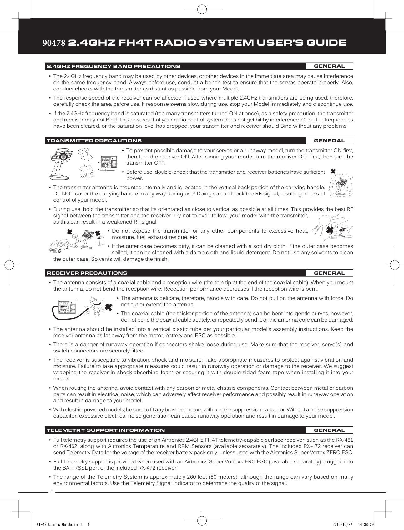
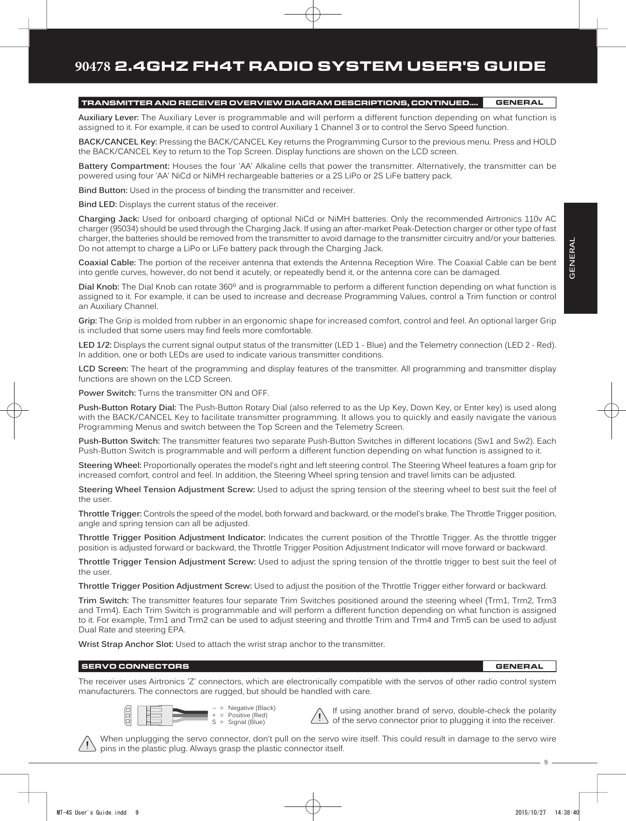
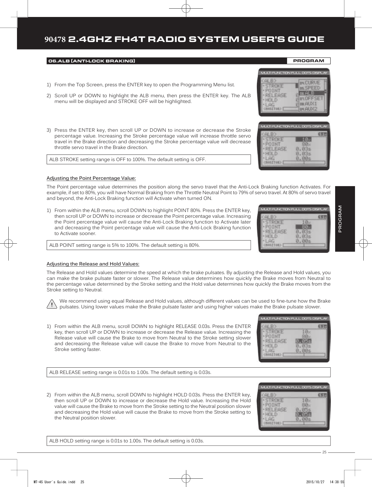
![2490478 2.4GHZ FH4T RADIO SYSTEM USER'S GUIDETRTRTRAdjusting the Return to Neutral Speed Value:1) From within the SPEED menu, scroll UP or DOWN to highlight the desired channelyou would like to change the Return to Neutral Speed value for. Choose from either[ST]:RETURN 0 (Steering), [TH]:RETURN 0 (Throttle), [A1]:RETURN 0 (Auxiliary 1) or[A2]:RETURN 0 (Auxiliary 2).2) Press the ENTER key, then scroll DOWN to decrease servo Speed in the Return toNeutral direction. Decreasing the Return to Neutral Speed value will cause the servotransit time to slow down when it moves from either End Point to the Neutral position.SPEED RETURN setting range is -100 to 0. The default setting is 0 (Normal Speed).Controlling the Servo Speed Function:1) By assigning the Steering and Throttle Forward and Return to Neutral Speed programming functions to one or more of theTrim Switches, Auxiliary Lever or Dial Knob, these functions can be adjusted while driving without accessing the Programming Menu. In addition, the Steering Speed and Throttle Speed functions can be Toggled OFF and ON by assigning them to oneor more Push-Button Switches. For more information, see the Key Assignments section on pages 53 through 58.Auxiliary 1 and Auxiliary 2 Forward and Return to Neutral Speed programming functions cannot be assigned.The Anti-Lock Braking function makes it possible to achieve stable braking even on a slippery surface. With stable braking, your model is better able to trace an exact line under braking. The Anti-Lock Braking function also enables you to set different braking characteristics depending on your particular model. Different Anti-Lock Braking function options can be custom programmed, including the how quickly the brake pulsates, the point at which the Anti-Lock Braking function starts and more.The Anti-Lock Braking function is primarily used on gasoline- or glow-powered models that feature a throttle servo. It can be used on an electric model that uses an Electronic Speed Control, however, if your Electronic Speed Control features a reverse function, the Anti-Lock Braking function will not operate properly.Adjusting the Stroke Percentage Value:The Stroke percentage value determines the amount of Brake that's applied automatically when the Anti-Lock Braking function Activates. When set to OFF, the Anti-Lock Braking function will not work. A percentage value of 1% or greater must be programmed for the Anti-Lock Braking function to operate.When the Anti-Lock Braking function is Active, LED 1 (Blue) will flash rapidly.05.SPEED (SERVO SPEED)PROGRAM06.ALB (ANTI-LOCK BRAKING)PROGRAMThe Anti-Lock Braking function operates only when the Throttle Trigger is moved from Neutral to the Brake Side. Set the hardest Braking you can obtain from your model by carefully setting the Anti-Lock Braking function right before the tires fully lock up but do not slip and lose traction. Be aware that using the Anti-Lock Braking function will never result in your model losing traction under braking. It only improves braking under less than ideal conditions.With ABS ON With ABS OFFThrottle NeutralPointLagReleaseHoldStrokeThe diagram at Right illustrates the relationship between the Point, Lag, Release, Hold and Stroke functions, all of which can be programmed separately to suit your specific car type, track conditions and Anti-Lock Braking behavior.MT-4S User's Guide.indd 24 2015/10/27 14:38:54](https://usermanual.wiki/Sanwa-Electronic-Instrument-Co/90478.User-Manual-1/User-Guide-2816265-Page-23.png)
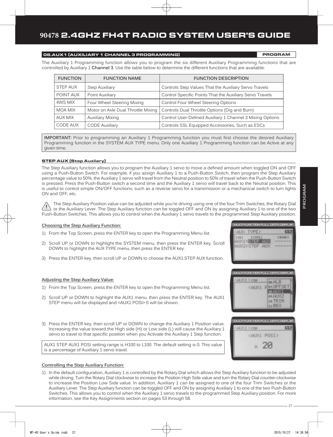
![2890478 2.4GHZ FH4T RADIO SYSTEM USER'S GUIDETRTRTRThe Point Auxiliary function allows you to program the Auxiliary 1 servo to move up to 6 different Points along its travel, then cycle through those Points using one of the Trim Switches or the Rotary Dial. For example, if your model requires a separate 3-position or more switch to operate a feature, the Point Auxiliary function can be customized to control this.Use one of the four Trim Switches or the Rotary Dial to cycle through the Point positions while you're driving. The Point Auxiliary function can be toggled OFF and ON while you're driving by assigning Auxiliary 1 to one of the two Push-Button Switches. To ensure correct operation, make sure to refer the Important notice in the Controlling the Point Auxiliary Function below.08.AUX1 (AUXILIARY 1 CHANNEL 3 PROGRAMMING)PROGRAMPOINT AUX (Point Auxliary)Choosing the Point Auxiliary Function and the Number of Points:1) From the Top Screen, press the ENTER key to open the Programming Menu list.2) Scroll UP or DOWN to highlight the SYSTEM menu, then press the ENTER key. ScrollDOWN to highlight the AUX TYPE menu, then press the ENTER key.3) Press the ENTER key, then scroll UP or DOWN to choose the AUX1:POINT AUX function.4) From within the AUX TYPE menu, scroll DOWN to highlight [MODE] 6 POINT. Press theENTER key, then scroll UP or DOWN to choose the desired number of Points you wouldlike to program.AUX TYPE POINT setting range is 2point to 6point. The default setting is 6point.Adjusting the Point Auxiliary Values:1) From the Top Screen, press the ENTER key to open the Programming Menu list.2) Scroll UP or DOWN to highlight the AUX1 menu, then press the ENTER key. The AUX1POINT menu will be displayed and the last Point selected will be highlighted.3) Scroll UP or DOWN to move the brackets to the Point you would like to change, thenpress the ENTER key to highlight that Point.4) Press the ENTER key, then scroll UP or DOWN to change the Point value. Increasing thePoint value toward the High side (H) or Low side (L) will cause the Auxiliary 1 servo totravel to that specific position when you cycle through the various Points.5) Repeat steps 3 and 4 to change the desired remaining Point values.AUX1 POINT setting range is H100 to L100. The default setting for Point 1 is L100, for Point 2 is L60, for Point 3 is L20, for Point 4 is H20, for Point 5 is H60, and for Point 6 is H100. These values are a percentage of Auxiliary 1 servo travel. Controlling the Point Auxiliary Function:1) In the default configuration, Auxiliary 1 is controlled by the Rotary Dial. Turn the Rotary Dial clockwise to cycle Forwardthrough the programmed Point Auxiliary positions and turn the Rotary Dial counter-clockwise to cycle Backward throughthe programmed Point Auxiliary positions. The Auxiliary 1 servo will move to the specified Point positions as you cyclethrough the different Points.In addition, Auxiliary 1 can be assigned to one of the four Trim Switches. The Point Auxiliary function can be toggled OFFand ON by assigning Auxiliary 1 to one of the two Push-Button Switches. For more information, see the Key Assignmentssection on pages 53 through 58.IMPORTANT: To operate correctly, the TRIM or DIAL Step value must be set to 1. If set to a value other than 1, Point positions will be skipped as you cycle through them. For more information, see the Key Assignments section on pages 53 through 58.MT-4S User's Guide.indd 28 2015/10/27 14:38:56](https://usermanual.wiki/Sanwa-Electronic-Instrument-Co/90478.User-Manual-1/User-Guide-2816265-Page-27.png)
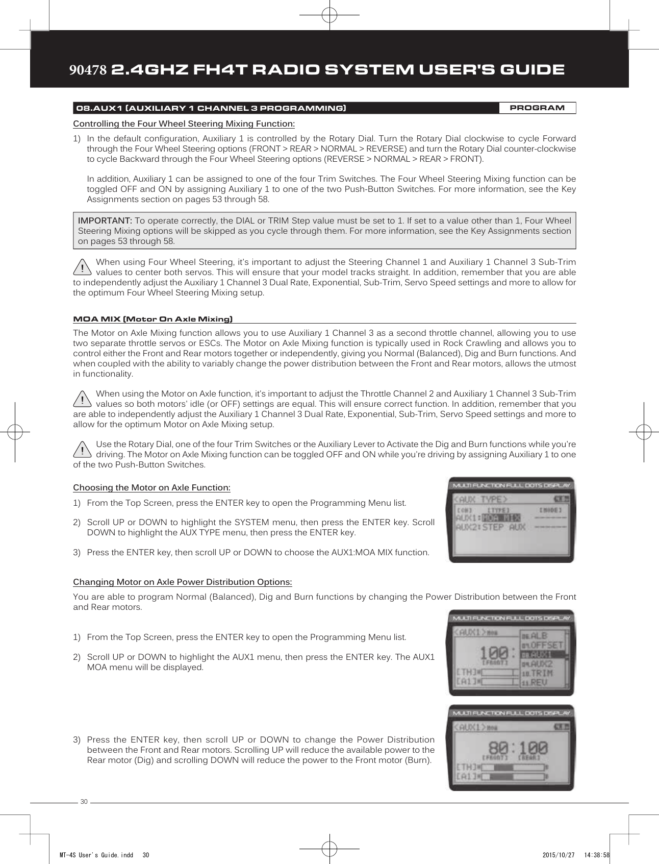
![31TRTRTR90478 2.4GHZ FH4T RADIO SYSTEM USER'S GUIDE08.AUX1 (AUXILIARY 1 CHANNEL 3 PROGRAMMING)PROGRAMPROGRAMFRONT Throttle (Burn) - When set to 0:100, power will only be distributed to the Rear motor (Burn). Power can be distributed proportionally between the Front and Rear motors from 0:100 to 99:100.REAR Throttle (Dig) - When set to 100:0, power will only be distributed to the Front motor (Dig). Power can be distributed proportionally between the Front and Rear motors from 100:0 to 100:99.OFF (Balanced) - When set to 100:100, power will be evenly distributed between the Front and Rear motors.The following Motor on Axle Mixing options can be programmed:Controlling the Motor on Axle Mixing Function:1) In the default configuration, Auxiliary 1 is controlled by the Rotary Dial. Turn the Rotary Dial clockwise to reduce the available power to the Rear motor (Dig) and turn the Rotary Dial counter-clockwise to reduce the power to the Front motor (Burn).In addition, Auxiliary 1 can be assigned to one of the four Trim Switches or to the Auxiliary Lever. The Motor on Axle Mixingfunction can be toggled OFF and ON by assigning Auxiliary 1 to one of the two Push-Button Switches. For more information,see the Key Assignments section on pages 53 through 58.IMPORTANT: In the default configuration, the Rotary Dial Step value is set to 5. This allows you to adjust the Power Distribution in 5 percent increments. If you prefer to control the Dig and Burn functions as if they were assigned to an ON/OFF switch, change the DIAL Step value to 100. Alternately, the Motor on Axle Mixing function can be controlled by the Auxiliary Lever. This allows you to quickly switch between the Dig and Burn functions and still have the ability to variably change the Power Distribution between the Front and Rear motors. To set this up, change the Auxiliary Lever Function to AUX1, then change the TWEAK (H) value to +100 and the TWEAK (L) value to -100. For more information, see the Key Assignments section on pages 53 through 58.The Auxiliary Mixing function allows you to Mix either Steering Channel 1 or Throttle Channel 2 to Auxiliary 1 Channel 3, while maintaining separate Sub-Trim, End Point Adjustments, Servo Reversing and other channel-specific settings. For example, if your monster truck features dual Front steering servos, instead of using a Y-Harness to join the two steering servos, you can use Steering Mixing to operate both steering servos together and still be able to make adjustments to each servo separately.In addition, if your model features a third-channel brake, you could use Throttle Mixing to control it along with the channel 2 brake.The Auxiliary Mixing Rate percentage value can be adjusted while you're driving using one of the four Trim Switches, the Rotary Dial or the Auxiliary Lever. The Auxiliary Mixing function can be toggled OFF and ON while you're driving by assigning Auxiliary 1 to one of the two Push-Button Switches.AUX MIX (Auxiliary Mixing)Choosing the Auxiliary Mixing Function and the Mixing Type:1) From the Top Screen, press the ENTER key to open the Programming Menu list.2) Scroll UP or DOWN to highlight the SYSTEM menu, then press the ENTER key. ScrollDOWN to highlight the AUX TYPE menu, then press the ENTER key.3) Press the ENTER key, then scroll UP or DOWN to choose the AUX1:AUX MIX function.4) From within the AUX TYPE menu, scroll DOWN to highlight [MODE] ST-mix. Press theENTER key, then scroll UP or DOWN to choose the desired Mixing type you would liketo program. Choose from either ST-mix (Steering Mixing) or TH-mix (Throttle Mixing).AUX TYPE MIX setting range is ST-mix and TH-mix. The default setting is ST-mix.MT-4S User's Guide.indd 31 2015/10/27 14:38:58](https://usermanual.wiki/Sanwa-Electronic-Instrument-Co/90478.User-Manual-1/User-Guide-2816265-Page-30.png)
![33TRTRTR90478 2.4GHZ FH4T RADIO SYSTEM USER'S GUIDEPROGRAM08.AUX1 (AUXILIARY 1 CHANNEL 3 PROGRAMMING)PROGRAMChanging CODE Auxiliary Values:1) From the Top Screen, press the ENTER key to open the Programming Menu list.2) Scroll UP or DOWN to highlight the AUX1 menu, then press the ENTER key. The AUX1CODE menu will be displayed.3) Press the ENTER key to open the AUX1 CODE menu. A1CODE1:CODE1 > 0 will behighlighted.4) Scroll UP or DOWN to highlight the desired CODE Auxiliary value you would like tochange.5) Press the ENTER key, then scroll UP or DOWN to choose the desired CODE Auxiliaryvalue.6) Press the ENTER key again, then repeat steps 3 and 4 to change any other desired CODE Auxiliary values.Refer to the Airtronics or Sanwa brand accessory's User's Guide for information about what CODE Auxiliary value (or values) control what accessory functions and what actual values to use.A1CODE1, A1CODE2, A1CODE3, A1CODE4 and A1CODE5 setting range is -100 to 100. The default setting for all CODE Auxiliary functions is 0. Changing CODE Programming Names:You are able to rename the different CODE Programming Names (CODE1, CODE2, etc) to make them easier to keep track of. The CODE Programming Name can consist of up to 5 letters, numbers, or symbols. Choose from capital letters, lower case letters, numbers, and various symbols.1) From within the AUX1 CODE menu, scroll UP or DOWN to highlight the desired CODEAuxiliary Name you want to change (CODE1, CODE2, etc.)2) Press the ENTER key. The AUX1 CODE menu will be displayed, [BACK] will be highlightedand the underscore will be flashing under the first editable character in the CODEProgramming Name.3) Scroll UP or DOWN to move the underscore to the character you would like change.4) Press the ENTER key, then scroll UP or DOWN to highlight a character in the CharacterList. Press the ENTER key a second time to select the highlighted character. Thatcharacter will be displayed and the underscore will move to the next space in the CODEProgramming Name.5) Repeat steps 3 and 4 to enter the rest of the characters. Up to five characters can be entered. Press the BACK/CANCEL keyto re-gain control of the underscore (the underscore will flash indicating you can scroll UP or DOWN to move it Forward orBackward). To select lower case letters, numbers or symbols, continue to scroll UP or DOWN through the various CharacterLists. To add a space in your Model Name, use the icon. The icon can also be used to delete characters.If you can't move the underscore, press the BACK/CANCEL key to re-gain control of the underscore (the underscore will flash indicating you can scroll UP or DOWN to move it Forward or Back).Controlling the CODE Auxiliary Function:1) In the default configuration, Auxiliary 1 is controlled by the Rotary Dial. To adjust the CODE Auxiliary function while driving youmust assign the desired CODE Auxiliary value (A1CODE1, A1 CODE2, etc) to either the Rotary Dial or one of the Trim Switches.In addition, the CODE Auxiliary function can be toggled OFF and ON by assigning Auxiliary 1 or the desired CODE Auxiliaryvalue (A1CODE1, A1 CODE2, etc) to one of the two Push-Button Switches. For more information, see the Key Assignmentssection on pages 53 through 58.MT-4S User's Guide.indd 33 2015/10/27 14:38:59](https://usermanual.wiki/Sanwa-Electronic-Instrument-Co/90478.User-Manual-1/User-Guide-2816265-Page-32.png)
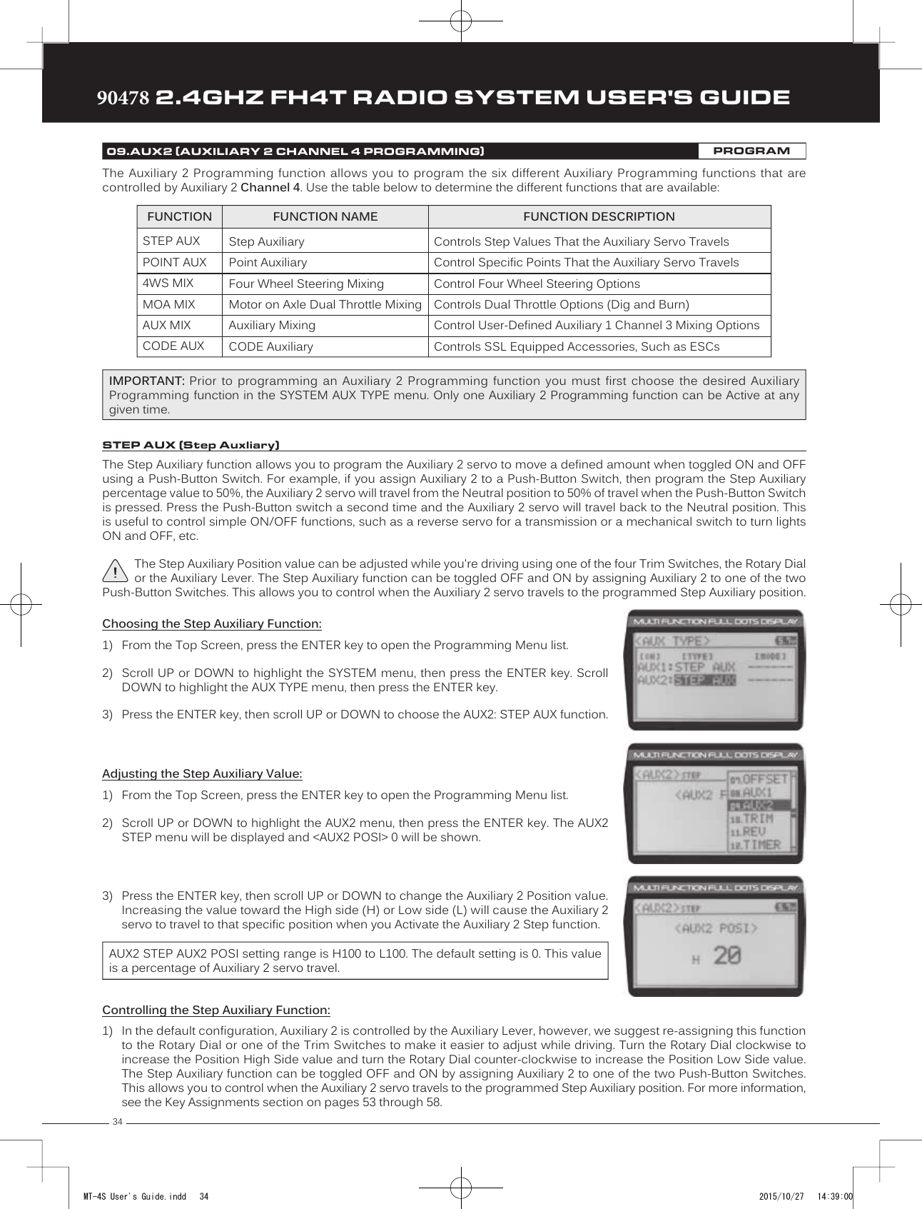
![35TRTRTR90478 2.4GHZ FH4T RADIO SYSTEM USER'S GUIDEThe Point Auxiliary function allows you to program the Auxiliary 2 servo to move up to 6 different Points along its travel, then cycle through those Points using one of the Trim Switches or the Rotary Dial. For example, if your model requires a separate 3-position or more switch to operate a feature, the Point Auxiliary function can be customized to control this.Use one of the four Trim Switches or the Rotary Dial to cycle through the Point positions while you're driving. The Point Auxiliary function can be toggled OFF and ON while you're driving by assigning Auxiliary 2 to one of the two Push-Button Switches. To ensure correct operation, make sure to refer the Important notice in the Controlling the Point Auxiliary Function below.09.AUX2 (AUXILIARY 2 CHANNEL 4 PROGRAMMING)PROGRAMPOINT AUX (Point Auxliary)Choosing the Point Auxiliary Function and the Number of Points:1) From the Top Screen, press the ENTER key to open the Programming Menu list.2) Scroll UP or DOWN to highlight the SYSTEM menu, then press the ENTER key. ScrollDOWN to highlight the AUX TYPE menu, then press the ENTER key.3) Press the ENTER key, then scroll UP or DOWN to choose the AUX2: POINT AUX function.4) From within the AUX TYPE menu, scroll DOWN to highlight [MODE] 6 POINT. Press theENTER key, then scroll UP or DOWN to choose the desired number of Points you wouldlike to program.AUX TYPE POINT setting range is 2point to 6point. The default setting is 6point.Adjusting the Point Auxiliary Values:1) From the Top Screen, press the ENTER key to open the Programming Menu list.2) Scroll UP or DOWN to highlight the AUX2 menu, then press the ENTER key. The AUX2POINT menu will be displayed and the last Point selected will be highlighted.3) Scroll UP or DOWN to move the brackets to the Point you would like to change, thenpress the ENTER key to highlight that Point.4) Press the ENTER key, then scroll UP or DOWN to change the Point value. Increasing thePoint value toward the High side (H) or Low side (L) will cause the Auxiliary 2 servo totravel to that specific position when you cycle through the various Points.5) Repeat steps 3 and 4 to change the desired remaining Point values.AUX2 POINT setting range is H100 to L100. The default setting for Point 1 is L100, for Point 2 is L60, for Point 3 is L20, for Point 4 is H20, for Point 5 is H60, and for Point 6 is H100. These values are a percentage of Auxiliary 2 servo travel. Controlling the Point Auxiliary Function:1) In the default configuration, Auxiliary 2 is controlled by the Auxiliary Lever, however, we suggest re-assigning this function to the Rotary Dial or one of the Trim Switches to make it easier to adjust while driving. Turn the Rotary Dial clockwise to cycle Forward through the programmed Point Auxiliary positions and turn the Rotary Dial counter-clockwise to cycle Backwardthrough the programmed Point Auxiliary positions. The Auxiliary 2 servo will move to the specified Point positions asyou cycle through the different Points.In addition, the Point Auxiliary function can be toggled OFF and ON by assigning Auxiliary 2 to one of the two Push-ButtonSwitches. For more information, see the Key Assignments section on pages 53 through 58.IMPORTANT: To operate correctly, the TRIM or DIAL Step value must be set to 1. If set to a value other than 1, Point positions will be skipped as you cycle through them. For more information, see the Key Assignments section on pages 53 through 58.PROGRAMMT-4S User's Guide.indd 35 2015/10/27 14:39:00](https://usermanual.wiki/Sanwa-Electronic-Instrument-Co/90478.User-Manual-1/User-Guide-2816265-Page-34.png)
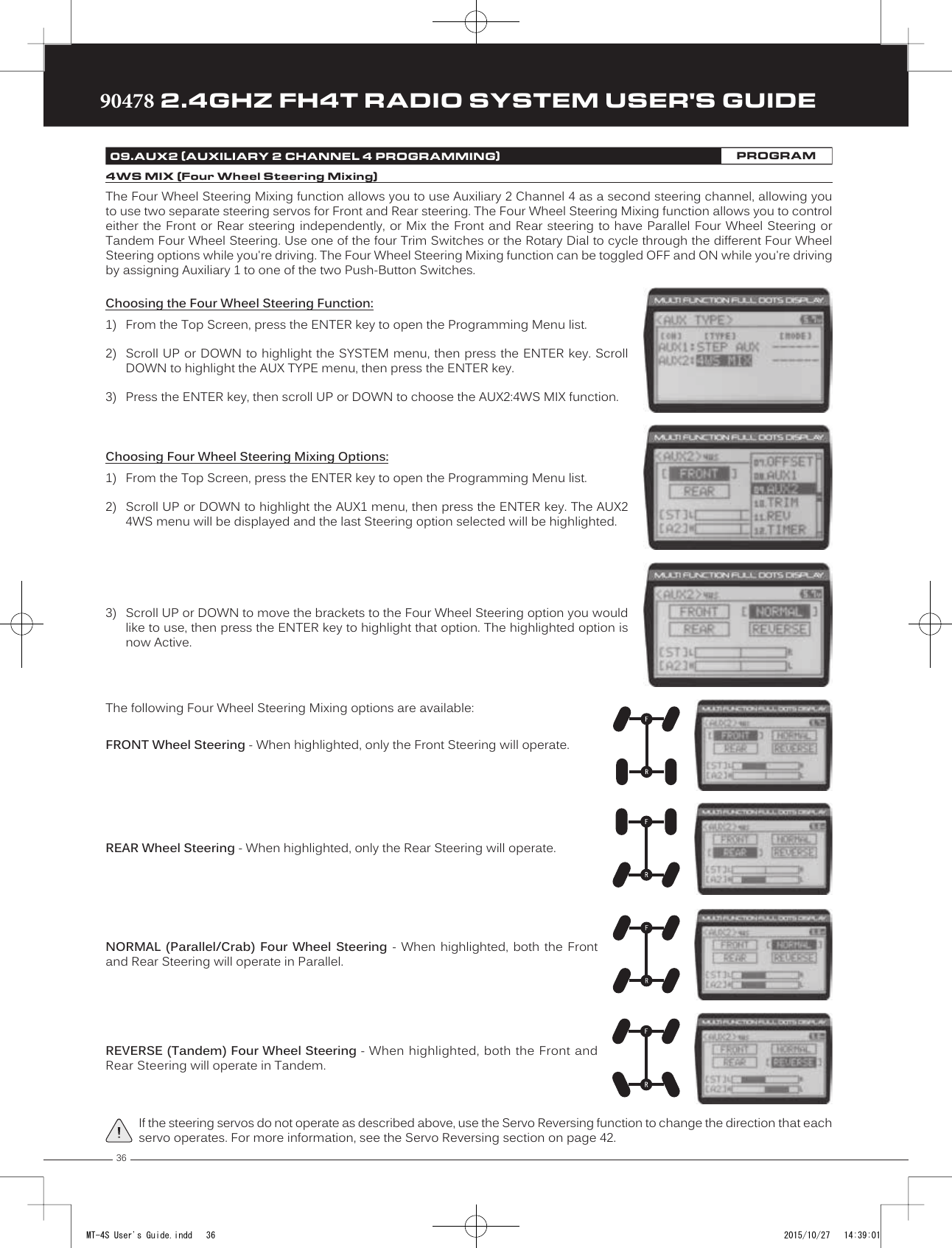
![3890478 2.4GHZ FH4T RADIO SYSTEM USER'S GUIDETRTRTR09.AUX2 (AUXILIARY 2 CHANNEL 4 PROGRAMMING)PROGRAMFRONT Throttle (Burn) - When set to 0:100, power will only be distributed to the Rear motor (Burn). Power can be distributed proportionally between the Front and Rear motors from 0:100 to 99:100.REAR Throttle (Dig) - When set to 100:0, power will only be distributed to the Front motor (Dig). Power can be distributed proportionally between the Front and Rear motors from 100:0 to 100:99.OFF (Balanced) - When set to 100:100, power will be evenly distributed between the Front and Rear motors.The following Motor on Axle Mixing options can be programmed:Controlling the Motor on Axle Mixing Function:1) In the default configuration, Auxiliary 2 is controlled by the Auxiliary Lever. This allows you to quickly switch between the Dig and Burn functions and still have the ability to variably change the Power Distribution between the Front and Rear motors. To set thisup, change the Auxiliary Lever Function to AUX2, then change the TWEAK (H) value to +100 and the TWEAK (L) value to -100. Formore information, see the Key Assignments section on pages 53 through 58. In addition, Auxiliary 2 can be assigned to theRotary Dial or one of the four Trim Switches. The Motor on Axle Mixing function can be toggled OFF and ON by assigningAuxiliary 2 to one of the two Push-Button Switches. For more information, see the Key Assignments section on pages 53through 58.IMPORTANT: In the default configuration, the Rotary Dial Step value is set to 5. This allows you to adjust the Power Distribution in 5 percent increments. If you prefer to control the Dig and Burn functions as if they were assigned to an ON/OFF switch, change the DIAL Step value to 100. For more information, see the Key Assignments section on pages 53 through 58.The Auxiliary Mixing function allows you to Mix either Steering Channel 1 or Throttle Channel 2 to Auxiliary 2 Channel 4, while maintaining separate Sub-Trim, End Point Adjustments, Servo Reversing and other channel-specific settings. For example, if your monster truck features dual Front steering servos, instead of using a Y-Harness to join the two steering servos, you can use Steering Mixing to operate both steering servos together and still be able to make adjustments to each servo separately.In addition, if your model features a third-channel brake, you could use Throttle Mixing to control it along with the channel 2 brake.The Auxiliary Mixing Rate percentage value can be adjusted while you're driving using one of the four Trim Switches, the Rotary Dial or the Auxiliary Lever. The Auxiliary Mixing function can be toggled OFF and ON while you're driving by assigning Auxiliary 2 to one of the two Push-Button Switches.AUX MIX (Auxiliary Mixing)Choosing the Auxiliary Mixing Function and the Mixing Type:1) From the Top Screen, press the ENTER key to open the Programming Menu list.2) Scroll UP or DOWN to highlight the SYSTEM menu, then press the ENTER key. ScrollDOWN to highlight the AUX TYPE menu, then press the ENTER key.3) Press the ENTER key, then scroll UP or DOWN to choose the AUX2:AUX MIX function.4) From within the AUX TYPE menu, scroll DOWN to highlight [MODE] ST-mix. Press theENTER key, then scroll UP or DOWN to choose the desired Mixing type you would liketo program. Choose from either ST-mix (Steering Mixing) or TH-mix (Throttle Mixing).AUX TYPE MIX setting range is ST-mix and TH-mix. The default setting is ST-mix.MT-4S User's Guide.indd 38 2015/10/27 14:39:02](https://usermanual.wiki/Sanwa-Electronic-Instrument-Co/90478.User-Manual-1/User-Guide-2816265-Page-37.png)
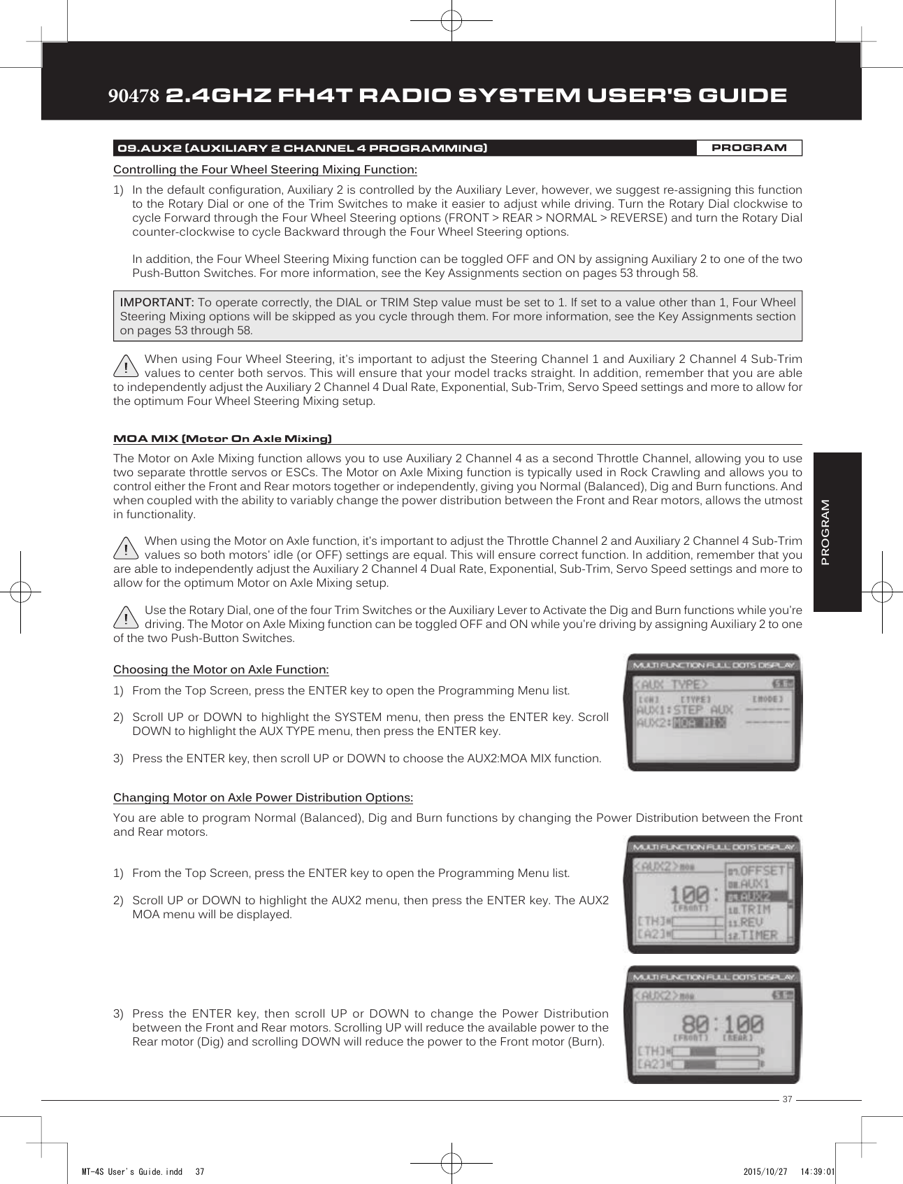
![4090478 2.4GHZ FH4T RADIO SYSTEM USER'S GUIDETRTRTR09.AUX2 (AUXILIARY 2 CHANNEL 4 PROGRAMMING)PROGRAMChanging CODE Auxiliary Values:1) From the Top Screen, press the ENTER key to open the Programming Menu list.2) Scroll UP or DOWN to highlight the AUX2 menu, then press the ENTER key. The AUX2CODE menu will be displayed.3) Press the ENTER key to open the AUX2 CODE menu. A2CODE1:CODE1 > 0 will behighlighted.4) Scroll UP or DOWN to highlight the desired CODE Auxiliary value you would like tochange.5) Press the ENTER key, then scroll UP or DOWN to choose the desired CODE Auxiliaryvalue.6) Press the ENTER key again, then repeat steps 3 and 4 to change any other desired CODE Auxiliary values.Refer to the Airtronics or Sanwa brand accessory's User's Guide for information about what CODE Auxiliary value (or values) control what accessory functions and what actual values to use.A2CODE1, A2CODE2, A2CODE3, A2CODE4 and A2CODE5 setting range is -100 to 100. The default setting for all CODE Auxiliary functions is 0. Changing CODE Programming Names:You are able to rename the different CODE Programming Names (CODE1, CODE2, etc) to make them easier to keep track of. The CODE Programming Name can consist of up to 5 letters, numbers, or symbols. Choose from capital letters, lower case letters, numbers, and various symbols.1) From within the AUX2 CODE menu, scroll UP or DOWN to highlight the desired CODEAuxiliary Name you want to change (CODE1, CODE2, etc.)2) Press the ENTER key. The AUX2 CODE menu will be displayed, [BACK] will be highlightedand the underscore will be flashing under the first editable character in the CODEProgramming Name.3) Scroll UP or DOWN to move the underscore to the character you would like change.4) Press the ENTER key, then scroll UP or DOWN to highlight a character in the CharacterList. Press the ENTER key a second time to select the highlighted character. Thatcharacter will be displayed and the underscore will move to the next space in the CODEProgramming Name.5) Repeat steps 3 and 4 to enter the rest of the characters. Up to five characters can be entered. Press the BACK/CANCEL keyto re-gain control of the underscore (the underscore will flash indicating you can scroll UP or DOWN to move it Forward orBackward). To select lower case letters, numbers or symbols, continue to scroll UP or DOWN through the various CharacterLists. To add a space in your Model Name, use the icon. The icon can also be used to delete characters.If you can't move the underscore, press the BACK/CANCEL key to re-gain control of the underscore (the underscore will flash indicating you can scroll UP or DOWN to move it Forward or Back).Controlling the CODE Auxiliary Function:1) In the default configuration, Auxiliary 2 is controlled by the Auxiliary Lever. To adjust the CODE Auxiliary function while driving youmust assign the desired CODE Auxiliary value (A2CODE1, A2 CODE2, etc) to either the Rotary Dial or one of the Trim Switches.In addition, the CODE Auxiliary function can be toggled OFF and ON by assigning Auxiliary 2 or the desired CODE Auxiliaryvalue (A2CODE1, A2 CODE2, etc) to one of the two Push-Button Switches. For more information, see the Key Assignmentssection on pages 53 through 58.MT-4S User's Guide.indd 40 2015/10/27 14:39:03](https://usermanual.wiki/Sanwa-Electronic-Instrument-Co/90478.User-Manual-1/User-Guide-2816265-Page-39.png)
![41TRTRTR90478 2.4GHZ FH4T RADIO SYSTEM USER'S GUIDEThe Trim function allows you to view the currently programmed Trim value of each of the four channels and, if desired, allows you to change the Trim values using the Push-Button Rotary Dial from within the Trim menu. In addition to the Trim function, the Servo Sub-Trim function allows you to fine-tune the Neutral position of each servo. Adjusting the Servo Sub-Trim Values:It's not unusual that when you center a servo and install the servo horn, the servo horn is not exactly centered. The Sub-Trim function allows you to center the servo horn exactly, without altering the servo End Point travel. This is especially useful when using a Mix, such as Four Wheel Steering Mixing. For example, you can use the Sub-Trim function to adjust the Neutral Trim setting of your Front and Rear Steering servos independently to ensure your Model tracks straight.1) Install the servo horn (or servo saver for the Steering servo) onto your servo, making sure that the servo horn (or servo saver) is as close to being centered as possible. In some cases, you can get the servo horn closer to being centered by rotating the servo horn 180º and reinstalling it.2) From the Top Screen, press the ENTER key to open the Programming Menu list.3) Scroll UP or DOWN to highlight the TRIM menu, then press the ENTER key. The TRIMmenu will be displayed and [ST]:TRIM 0 will be highlighted.4) Scroll UP or DOWN to highlight the desired channel you would like to changethe Sub-Trim value for. Choose from either [ST]:[SUB-T] 0 (Steering), [TH]:[SUB-T] 0(Throttle), [A1]:[SUB-T] 0 (Auxiliary 1) or [A2]:[SUB-T] 0 (Auxiliary 2).PROGRAM10.TRIM (TRIM AND SERVO SUB-TRIM)PROGRAMBefore changing the Sub-Trim values you should set the Steering and Throttle Trim to 0 using the Trm1 and Trm2 Trim Switches.Trm1 [ST]Trm2 [TH]5) Press the ENTER key, then scroll UP or DOWN to increase or decrease the Sub-Trimvalue to center the servo horn.TRIM SUB-T setting range for the Steering channel is R150 to L150, for the Throttle channel is H150 to B150 and for Auxiliary 1 Channel 3 and Auxiliary 2 Channel 4 is H150 to L150. The default setting for all channels is 0.After adjusting the Sub-Trim value, use the End Point Adjustment function to set the desired amount of maximum servo travel in both directions. For more information, see the End Point Adjustment section on pages 19 through 21.Adjusting the Trim Values:The 90478 transmitter features Digital Trim Memory. Any amount of Trim that you set using the Trim Switches is automatically stored in memory for that specific channel and for that specific model. The Trim values for each model will automatically be loaded when the transmitter is turned ON.Before adjusting the Trim values, you should first adjust the servo Sub-Trim values to center the servo horns. For more information, see the Adjusting the Servo Sub-Trim Values section above.MT-4S User's Guide.indd 41 2015/10/27 14:39:04](https://usermanual.wiki/Sanwa-Electronic-Instrument-Co/90478.User-Manual-1/User-Guide-2816265-Page-40.png)
![4290478 2.4GHZ FH4T RADIO SYSTEM USER'S GUIDETRTRTR2) Press the ENTER key, then scroll UP or DOWN to increase or decrease the Trim value inthe desired direction.TRIM TRIM setting range for the Steering channel is R100 to L100, for the Throttle channel is H100 to B100 and for Auxiliary 1 Channel 3 and Auxiliary 2 Channel 4 is H100 to L100. The default setting for all channels is 0.1) From within the TRIM menu, scroll UP or DOWN to highlight the desired channel youwould like to change the Trim value for. Choose from either [ST]:[TRIM] 0 (Steering),[TH]:[TRIM] 0 (Throttle), [A1]:[TRIM] 0 (Auxiliary 1) or [A2]:[TRIM] 0 (Auxiliary 2).Controlling the Trim Function:1) In the default configuration, Trim Switch Trm1 controls the Steering Right and Left Trim and Trim Switch Trm2 controls theThrottle High and Brake Trim. When you move the Trim Switches, the Trim percentage value changes in 5% increments.When you use the Trim function to change the Trim value, the Trim value changes in 1% increments.Auxiliary 1 Trim and Auxiliary 2 Trim can be assigned to the remaining two Trim Switches, the Rotary Dial or the AuxiliaryLever. For more information, see the Key Assignments section on pages 53 through 58.Each time you move a Trim Switch a single audible tone is heard. When the Trim value reaches 0 (Centered), an audible double-tone sounds. This indicates to you that the Trim is centered without the need to look down at the Trim Indicator on the Top Screen while you're driving.PRO TIP: The Trim function features two different Trim Type options that you can choose from. Choose from either Center Trim or Parallel Trim. For more information, see the Trim Type section on page 59.10.TRIM (TRIM AND SERVO SUB-TRIM)PROGRAM11.REV (SERVO REVERSING)PROGRAMThe Servo Reversing function allows you to electronically switch the direction of servo travel. For example, if you rotate the steering wheel to the right, and the steering servo moves to the left, you can use the Servo Reversing function to make the steering servo move to the left. The Servo Reversing function is available for all four channels.Changing the Servo Reversing Values:1) From the Top Screen, press the ENTER key to open the Programming Menu list.2) Scroll UP or DOWN to highlight the REV menu, then press the ENTER key. The REVmenu will be displayed and [ST]:NOR will be highlighted.3) Scroll UP or DOWN to highlight the desired channel you would like to change the ServoReversing value for. Choose from either [ST]:NOR (Steering), [TH]:NOR (Throttle),[A1]:NOR (Auxiliary 1) or [A2]:NOR (Auxiliary 2).4) Press the ENTER key, then scroll UP or DOWN to change the direction of servo travel.REV setting range is NOR and REV. The default setting for all channels is NOR.When you change the direction of servo travel, the servo horn may no longer be centered. If this occurs, use the Servo Sub-Trim function to center the servo horn. For more information, see the Adjusting the Servo Sub-Trim Values section on page 41.MT-4S User's Guide.indd 42 2015/10/27 14:39:04](https://usermanual.wiki/Sanwa-Electronic-Instrument-Co/90478.User-Manual-1/User-Guide-2816265-Page-41.png)
![43TRTRTR90478 2.4GHZ FH4T RADIO SYSTEM USER'S GUIDEThe Track Timers function features three different Timers. Timers are provided for measuring Lap Times, Interval Times, and Countdown Times. Timers are displayed in the following format: 00:00.00 (Minutes:Seconds.1/100th of a Second). In the default configuration, Push-Button Switch Sw2 controls the selected timer. The selected timer is also displayed on the Top Screen in the following format: 00:00 (Minutes:Seconds).Choosing the Timer Type:1) From the Top Screen, press the ENTER key to open the Programming Menu list.2) Scroll UP or DOWN to highlight the TIMER menu, then press the ENTER key. The TIMERmenu will be displayed and [TYPE] LAP will be highlighted.3) Press the ENTER key, then scroll UP and DOWN to select the desired Timer Type.Choose from LAP, INT (Interval) and DOWN (Countdown).To program the Lap Timer function, see the Lap Timer section below. To program the Interval Timer function, see the Interval Timer section on pages 44 and 45. To program the Countdown Timer function, see the Countdown Timer section on page 45.PROGRAM12.TIMER (TRACK TIMERS)PROGRAMThe Lap Timer function allows you to measure and record times for up to 99 laps. The number of laps completed is displayed in the Timer menu, and when a lap is completed, the lap time is displayed momentarily on the Top Screen. An Alarm (Goal Time) is featured that will sound when you reach your Goal Time and, if desired, the Interval Timer (Target Time) can be programmed within the Lap Timer to alert you of your Target Time separately from your Goal Time.Setting the Interval Timer (Target Time):1) From within the TIMER menu, scroll DOWN to highlight [INT]:--.2) Press the ENTER key, then scroll UP or DOWN to set the desired Interval Timer Minutesvalue.TIMER INT setting range is --:-- . -- to 99:59:99. The default setting is --:-- . -- (OFF). When the Lap Timer is counting up, an audible double-tone will sound each time the Lap Timer reaches the Interval Timer value. For example, if you set the Interval Timer for 30 Seconds, an audible double-tone will sound every 30 seconds.3) To set the Interval Timer Seconds value, press the ENTER key, then scroll DOWN tohighlight --. Press the ENTER key a second time, then scroll UP and DOWN to set thedesired Interval Timer Seconds value.4) To set the Interval Timer 1/100th Seconds value, press the ENTER key, then scroll DOWNto highlight --. Press the ENTER key a second time, then scroll UP and DOWN to set thedesired Interval Timer 1/100th Seconds value.LAP (Lap Timer)Setting the Alarm (Goal Time):1) From within the TIMER menu, scroll DOWN to highlight [ALRM] 05.2) Press the ENTER key, then scroll UP or DOWN to set the desired Alarm Minutes value.3) To set the Alarm Seconds value, press the ENTER key, then scroll DOWN to highlight 00.Press the ENTER key a second time, then scroll UP and DOWN to set the desired AlarmSeconds value.TIMER ALRM setting range is 00:00 to 99:59. The default setting is 5:00 minutes. An audible tone will sound in 1 second intervals 5 seconds before reaching the Goal Time. When the Goal Time is reached, a long audible tone will sound.MT-4S User's Guide.indd 43 2015/10/27 14:39:05](https://usermanual.wiki/Sanwa-Electronic-Instrument-Co/90478.User-Manual-1/User-Guide-2816265-Page-42.png)
![4490478 2.4GHZ FH4T RADIO SYSTEM USER'S GUIDETRTRTRStarting the Lap Timer:1) In the default configuration, Push-Button Switch Sw2 controls the Lap Timer. Press and HOLD the Push-Button Switch for 3seconds. An audible double-tone will sound and LAP will flash on the Top Screen indicating the Lap Timer is in Stand-by.To start the Lap Timer, press the Push- Button Switch a second time or pull the Throttle Trigger. An audible double-tone willsound and the Lap Timer will start counting up.Pressing the Push-Button Switch a second time will store the first Lap Time, then begin counting a second Lap Time. Eachtime you press the Push-Button Switch, an audible tone sounds, the previous Lap Time is stored, a new Lap Time beginsand the current Lap Time is displayed momentarily on the Top Screen.If desired, the Timer Function can be assigned to Push-Button Switch Sw1. For more information, see the Key Assignments section on pages 53 through 58.Stopping the Lap Timer:1) To stop the Lap Timer, press and HOLD Push-Button Switch Sw2 for 3 seconds. An audible double-tone will sound indicatingthe Lap Timer is stopped and the Cumulative Time will be displayed on the Top Screen and in the TIMER menu.The Cumulative Time cannot be manually cleared. It will be automatically cleared when the Lap Timer is put in Stand-by again.The Interval Timer (Target Time) function notifies you when a set interval elapses while you are driving, giving you an idea of how close you are to your Target Time. An Alarm (Goal Time) is featured that will sound when you reach your Goal Time. When the Interval Time is reached, an audible Double-Tone will sound, then the Interval Timer will Reset and begin counting Up again from zero.Setting the Interval Timer (Target Time):1) From within the TIMER menu, scroll DOWN to highlight [INT]:--.2) Press the ENTER key, then scroll UP or DOWN to set the desired Interval Timer Minutesvalue.TIMER INT setting range is --:-- . -- to 99:59:99. The default setting is --:-- . -- (OFF). When the Interval Timer is started, an au-dible double-tone will sound each time the Interval Timer reaches the Interval Timer value. For example, if you set the Interval Timer for 1 Minute, an audible double-tone will sound every Minute.3) To set the Interval Timer Seconds value, press the ENTER key, then scroll DOWN tohighlight --. Press the ENTER key a second time, then scroll UP and DOWN to set thedesired Interval Timer Seconds value.4) To set the Interval Timer 1/100th Seconds value, press the ENTER key, then scroll DOWNto highlight --. Press the ENTER key a second time, then scroll UP and DOWN to set thedesired Interval Timer 1/100th Seconds value.Setting the Alarm (Goal Time):1) From within the TIMER menu, scroll DOWN to highlight [ALRM] 05.2) Press the ENTER key, then scroll UP or DOWN to set the desired Alarm Minutes value.TIMER ALRM setting range is 00:00 to 99:59. The default setting is 5:00 minutes. An audible tone will sound in 1 second intervals 5 seconds before reaching the Goal Time. When the Goal Time is reached, a long audible tone will sound.12.TIMER (TRACK TIMERS)PROGRAMINT (Interval Timer)3) To set the Alarm Seconds value, press the ENTER key, then scroll DOWN to highlight 00. Press the ENTER key a secondtime, then scroll UP and DOWN to set the desired Alarm Seconds value.MT-4S User's Guide.indd 44 2015/10/27 14:39:05](https://usermanual.wiki/Sanwa-Electronic-Instrument-Co/90478.User-Manual-1/User-Guide-2816265-Page-43.png)