Sanwa Electronic Instrument Co 90478 Digital High Response Telemetry System User Manual MT 4S User s Guide indd
Sanwa Electronic Instrument Co Ltd Digital High Response Telemetry System MT 4S User s Guide indd
Contents
- 1. User Manual-1
- 2. User Manual-2
User Manual-2
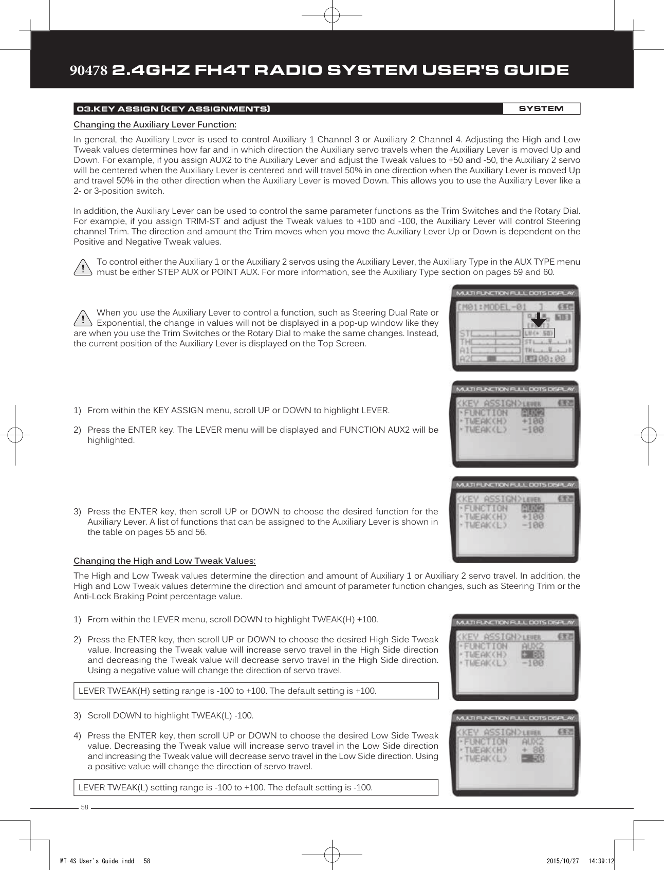
![45TRTRTR90478 2.4GHZ FH4T RADIO SYSTEM USER'S GUIDEStarting the Interval Timer:1) In the default configuration, Push-Button Switch Sw2 controls the Interval Timer. Press and HOLD the Push-Button Switchfor 3 seconds. An audible double-tone will sound and INT will flash on the Top Screen indicating the Interval Timer is inStand-by.To start the Interval Timer, press the Push-Button Switch a second time or pull the Throttle Trigger. An audible double-tone willsound and the Interval Timer will start counting up. Each time the programmed Interval Time elapses, an audible double-tone will sound and the Interval Timer will restart from zero and the Cumulative Time will be displayed on the Top Screen.You can manually restart the Interval Timer from zero by pressing the Push-Button Switch while the Interval Timer is running.If desired, the Timer Function can be assigned to Push-Button Switch Sw1. For more information, see the Key Assignments section on pages 53 through 58.Stopping the Interval Timer:1) To stop the Interval Timer, press and HOLD Push-Button Switch Sw2 for 3 seconds. An audible double-tone will soundindicating the Interval Timer is stopped and the Cumulative Time will be displayed on the Top Screen and in the TIMER menu.The Cumulative Time cannot be manually cleared. It will be automatically cleared when the Interval Timer is put in Stand-by again.12.TIMER (TRACK TIMERS)PROGRAMPROGRAMThe Countdown Timer function can be used to notify you of your model’s running time. For example, you can set the Countdown Timer to alert you when it's time to refuel. When the Countdown Timer expires, a long audible tone will sound and the Count Up Timer function begins automatically. This allows you to check the time elapsed since the Countdown Timer ran out.Setting the Alarm:1) From within the TIMER menu, scroll DOWN to highlight [ALRM] 05.2) Press the ENTER key, then scroll UP or DOWN to set the desired Alarm Minutes value.3) To set the Alarm Seconds value, press the ENTER key, then scroll DOWN to highlight 00.Press the ENTER key a second time, then scroll UP and DOWN to set the desired AlarmSeconds value.TIMER ALRM setting range is 00:00 to 99:59. The default setting is 5:00 minutes. An audible tone will sound in 1 second intervals 5 seconds before reaching the Countdown Alarm Time. When the Countdown Alarm Time is reached, a long audible tone will sound.Starting the Countdown Timer:1) In the default configuration, Push-Button Switch Sw2 controls the Countdown Timer. Press and HOLD the Push-ButtonSwitch for 3 seconds. An audible double-tone will sound and DWN will flash on the Top Screen indicating the CountdownTimer is in Stand-by.To start the Countdown Timer, press the Push-Button Switch a second time or pull the Throttle Trigger. An audibledouble-tone will sound and the Countdown Timer will start counting down. An audible tone will sound in 1 second intervals5 seconds before reaching zero. When zero is reached, a long audible tone will sound and the Countdown Timer will begincounting Up.You can manually stop the Countdown Timer at any time by pressing the Push-Button Switch. Press the Push-Button Switchagain will start the Countdown Timer from where it was stopped.If desired, the Timer Function can be assigned to Push-Button Switch Sw1. For more information, see the Key Assignments section on pages 53 through 58.Stopping the Countdown Timer:1) To stop the Countdown Timer, press and HOLD the Push-Button Switch for 3 seconds. An audible double-tone will soundindicating the Countdown Timer is stopped and either the remaining Countdown Time or elapsed Count Up Time will bedisplayed on the Top Screen and in the TIMER menu.The remaining Countdown Time or Count Up Time cannot be manually cleared. It will be automatically cleared when the Countdown Timer is put in Stand-by again.DOWN (Countdown Timer)MT-4S User's Guide.indd 45 2015/10/27 14:39:05](https://usermanual.wiki/Sanwa-Electronic-Instrument-Co/90478.User-Manual-2/User-Guide-2816266-Page-1.png)
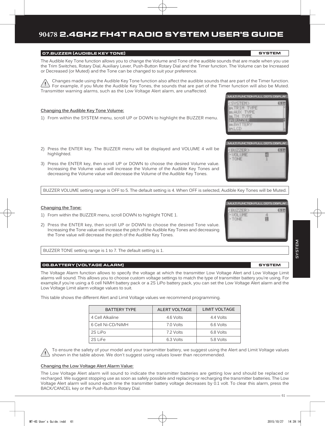
![4690478 2.4GHZ FH4T RADIO SYSTEM USER'S GUIDETRTRTRThe Lap Times menu displays a total of up to 99 laps that are recorded using the Lap Timer function. Each Lap Time is displayed along with the Best Lap Time and the Total (Cumulative) Lap Time.Viewing Lap Times:1) From the Top Screen, press the ENTER key to open the Programming Menu list.2) Scroll UP or DOWN to highlight the LAP menu, then press the ENTER key. The LAP menuwill be displayed and the last Lap selected will be highlighted.3) Scroll UP and DOWN to view the stored Lap Times. Lap Times are stored from the timeyou start the Lap Timer to the time you Stop the Lap Timer. The Total (Cumulative) LapTime and your Best Lap Time are always displayed at the top of the list.Lap Times are stored until you restart the Lap Timer function. When the Lap Timer function is restarted, old Lap Times are cleared and new Lap Times are stored.The Fail Safe function automatically moves the servos to a predetermined position in the event that the signal between the transmitter and the receiver is interrupted, whether due to signal degradation or to low transmitter battery. Several different setting options are available. The Fail Safe function can be set to Hold the servos in the last position they were in when the signal was lost, or each of the servos can be set to move to a custom position when the signal is lost. For example, the throttle servo moves to the Brake Side to engage the brakes and stop your model. If you're driving a gas- or glow-powered boat, the Fail Safe function could be set to lower the throttle to idle and turn the rudder slightly left or right so that the boat will continue in slow circles.In addition, a Receiver Battery Voltage Fail Safe function is available which allows you to set a custom voltage that the Receiver Battery Fail Safe function will Activate at. This is useful if you're using servos with a higher than normal current draw that might run out of power before the receiver does.Setting the Fail Safe:Fail Safe settings can be programmed for each of the four channels individually. In addition, Fail Safe settings are model-specific, meaning you can have different Fail Safe settings for each Model in memory. Three Fail Safe options are available for each channel as described below:FREE - Fail Safe is disabled for this channel. Servos can move freely when the signal is lost.HOLD - When Fail Safe Activates, the servo will be held in the last position it was in when the signal was lost. % (PERCENTAGE) - When Fail Safe Activates, the servo will travel to the programmed position when the signal is lost.IMPORTANT: The Fail Safe function will NOT OPERATE if the receiver loses power. It will operate only if the transmitter and receiver signal is interrupted or if the transmitter loses power.1) From the Top Screen, press the ENTER key to open the Programming Menu list.2) Scroll UP or DOWN to highlight the F/S menu, then press the ENTER key. The F/S menuwill be displayed and [ST]:FREE will be highlighted.3) Scroll UP or DOWN to highlight the desired channel you would like to change the FailSafe option for.4) Press the ENTER key, then scroll UP or DOWN to choose the desired Fail Safe option forthat channel. If you choose to program a % value, see step 5 below.F/S setting range is FREE, HOLD, or %. The default setting is FREE.13.LAP (LAP TIMES)PROGRAM14.F /S (FAIL SAFE)PROGRAMMT-4S User's Guide.indd 46 2015/10/27 14:39:06](https://usermanual.wiki/Sanwa-Electronic-Instrument-Co/90478.User-Manual-2/User-Guide-2816266-Page-2.png)
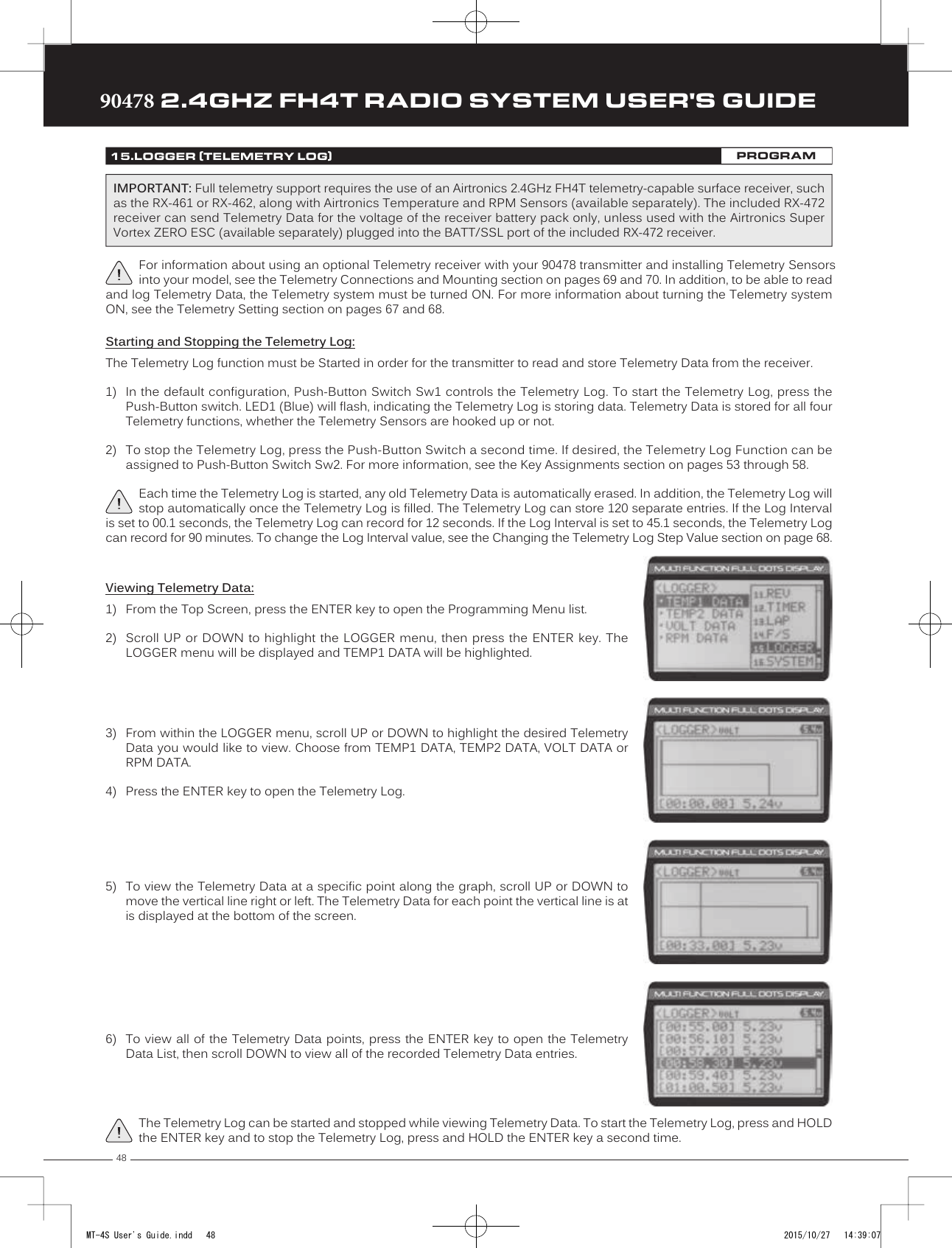
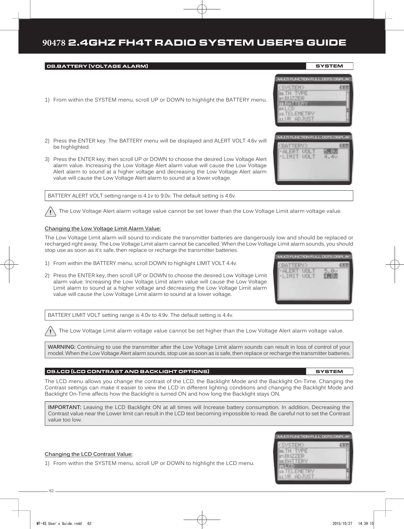
![47TRTRTR90478 2.4GHZ FH4T RADIO SYSTEM USER'S GUIDE5) To program a Fail Safe percentage value, move the control the amount you want theservo to move to when the Fail Safe function Activates and HOLD it in that position,then press and HOLD the ENTER key until an audible tone sounds. The percentage anddirection the servo will travel will be displayed. For example, to set the Throttle Brake toengage when the Fail Safe function Activates, push the throttle trigger toward the Brakeside the desired amount, HOLD the throttle trigger in that position, then press and HOLDthe ENTER key. The percentage value programmed will be indicated by two hash markson the Servo Monitor.6) Check to ensure your Fail Safe settings are working properly. Make sure that both the transmitter and receiver are turnedON, then, while someone is holding your model, turn the transmitter OFF. The servos should react correctly based on theFail Safe values chosen.The Fail Safe settings will be retained even if the transmitter loses power or if the transmitter and receiver must be paired again.When using an FH2 receiver with your transmitter, these Fail Safe features are not supported. In this case, the Fail Safe function must be programmed directly through the receiver. For more information, follow the Fail Safe Programming instructions provided with your FH2 receiver.14.F /S (FAIL SAFE)PROGRAMPROGRAMSetting the Receiver Battery Voltage Fail Safe Function:The Receiver Battery Voltage Fail Safe function is designed to alert you when your receiver battery requires recharging. This ensures that the receiver battery's voltage doesn't drop so low that your servos aren't provided adequate voltage to operate optimally. When Activated, the throttle servo will move to the predetermined position you programmed in step 5 in the Setting the Fail Safe section above. If this occurs, recharge or replace your receiver batteries.If FREE or HOLD is chosen for the Throttle channel, you cannot Activate the Receiver Battery Voltage Fail Safe function. A % value must be chosen for the Throttle channel to be able to program and use the Receiver Battery Fail Safe function.The Receiver Battery Voltage Fail Safe function works only with FH3 and FH4T receivers.1) Follow steps 1 through 5 in the Setting the Fail Safe section to program a Throttle FailSafe percentage value.2) From within the F/S menu, press the ENTER key, then scroll DOWN to highlight[B-F/S] OFF.3) Press the ENTER key, then scroll UP or DOWN to choose the desired Receiver BatteryFail Safe Voltage value. Many factors, such as the current draw of your servos and howmany servos you're using, etc., will determine the value to use. A good starting pointwould be 3.7V. If it appears your servos are slow or not producing adequate torque whatthat Voltage value is reached, Increase the Voltage value.WARNING: This function is designed for use with glow- or gas-powered Models that use a separate receiver battery pack. Do NOT use this function with an electric Model that uses the motor battery to power the servos and receiver.F/S B-F/S setting range for FH4T receivers is OFF and 3.5V to 7.4V. F/S B-F/S setting range for FH3 receivers is OFF and 3.5V to 5.0V. The default setting is OFF regardless of the Modulation Type chosen.The Telemetry Log function allows you to view a log of the Telemetry Data that is sent from the receiver to the transmitter. You are able to view Telemetry Data for both Temperature outputs, the RPM output and the receiver's Voltage. This information can be used to track specific information about your model, such as cylinder head temperature if you're running a nitro-powered model or battery temperature if you're running an electric model and much more. The interval that Telemetry Data is read and stored can be adjusted so that Telemetry Data can be stored for up to 90 minutes of use. The Telemetry Log can store 120 different data entries at intervals ranging from 00.1 seconds to 45.9 seconds. 15.LOGGER (TELEMETRY LOG)PROGRAMMT-4S User's Guide.indd 47 2015/10/27 14:39:06](https://usermanual.wiki/Sanwa-Electronic-Instrument-Co/90478.User-Manual-2/User-Guide-2816266-Page-3.png)
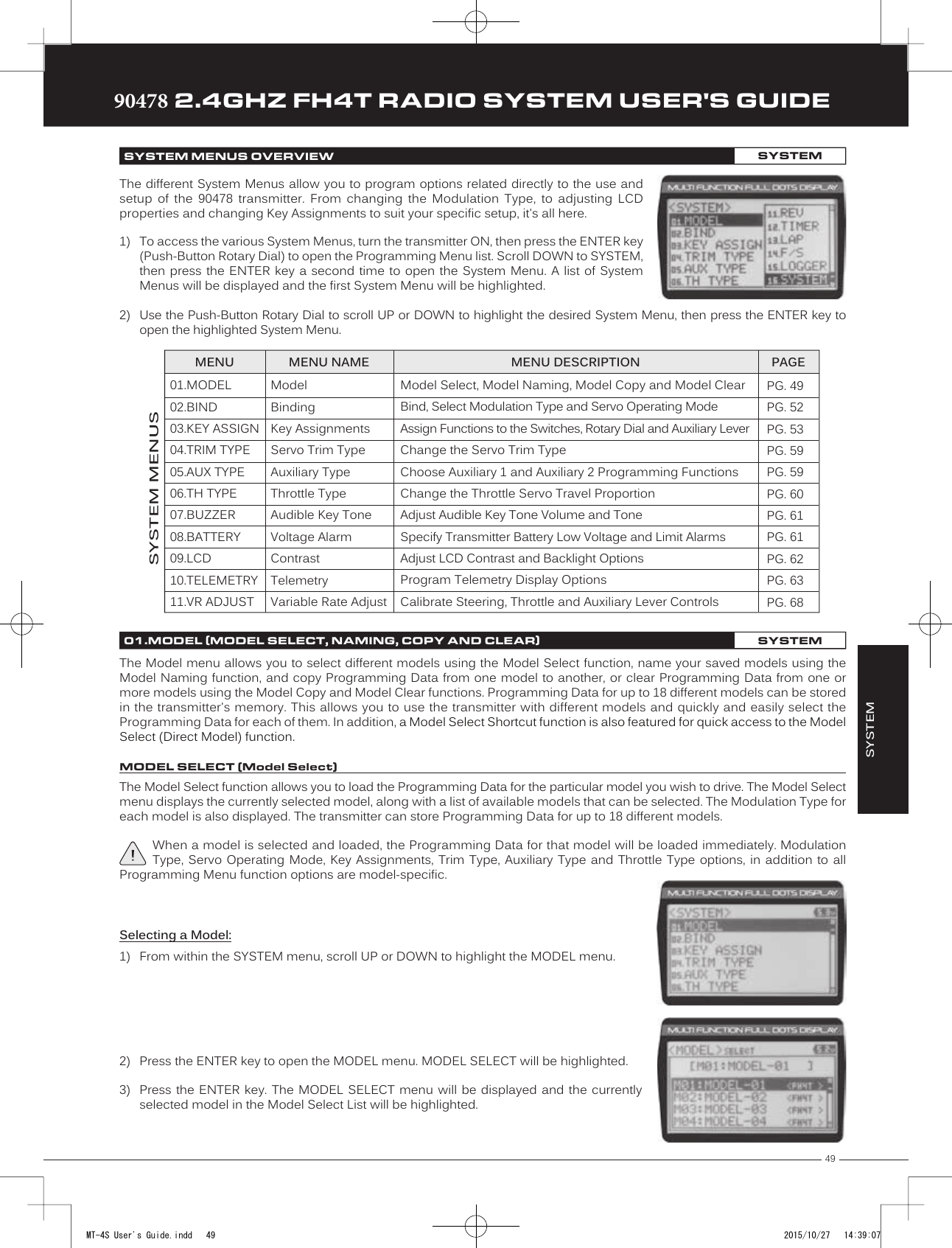
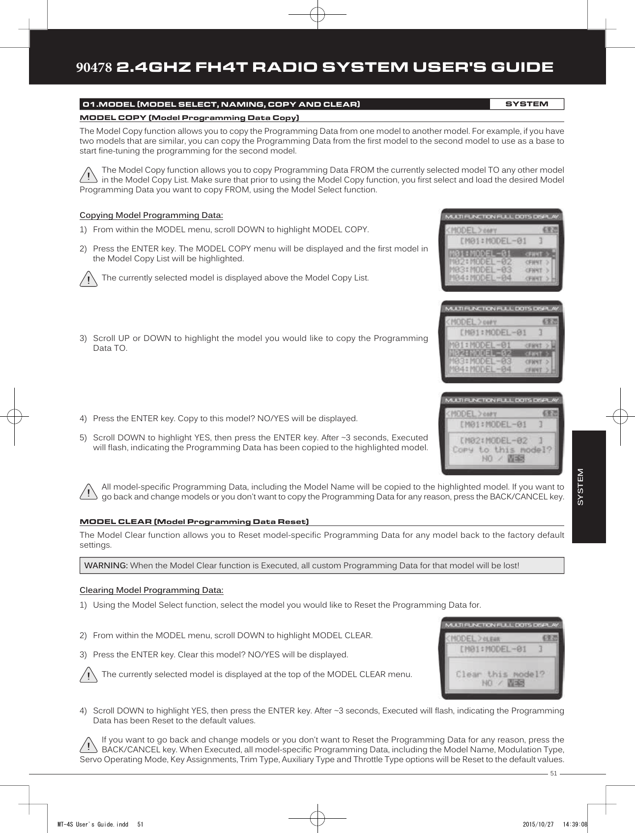
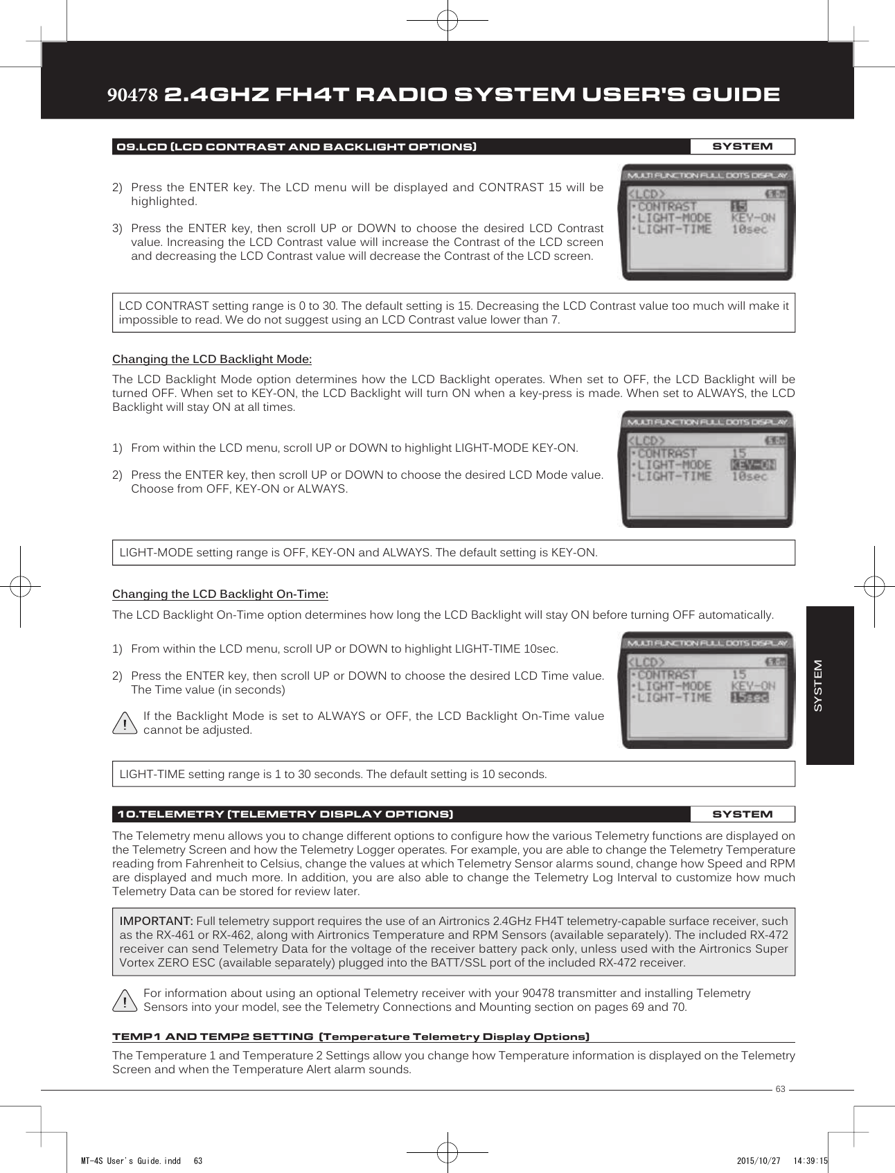
![5090478 2.4GHZ FH4T RADIO SYSTEM USER'S GUIDETRTRTR4) Scroll UP or DOWN to highlight the model you would like to select, then press the ENTERkey. Select this model? NO/YES will be displayed.5) Scroll DOWN to highlight YES, then press the ENTER key. The model that you justselected will be displayed above the Model Select List and that model's ProgrammingData will be loaded.Model Select Shortcut (Direct Model):The Model Select Shortcut function allows you to jump directly to the DIRECT MODEL menu when you turn the transmitter ON. This menu works the same as the MODEL SELECT menu and makes it much quicker select your desired model.The Model Naming function allows you to name each of the 18 individual models. This makes it easy to keep track of multiple models. The Model Name can consist of up to 10 letters, numbers, or symbols. Choose from capital letters, lower case letters, numbers, and various symbols.A model must be selected before a Model Name can be entered or modified. In the default configuration, M01:MODEL-1 is selected. To enter a Model Name for another model, that model must first be selected using the Model Select function or the Model Select Shortcut function. For more information, see the Model Select section on pages 49 and 50.Changing the Model Name:1) From within the MODEL menu, scroll DOWN to highlight MODEL NAME.2) Press the ENTER key. The MODEL NAME menu will be displayed, [BACK] will behighlighted and the underscore will be flashing under the first editable character in theModel Name.3) Scroll UP or DOWN to move the underscore to the character you would like change.4) Press the ENTER key, then scroll UP or DOWN to highlight a character in the CharacterList. Press the ENTER key a second time to select the highlighted character. Thatcharacter will be displayed and the underscore will move to the next space in the Model Name.01.MODEL (MODEL SELECT, NAMING, COPY AND CLEAR)SYSTEMMODEL NAME (Model Naming)5) Repeat steps 3 and 4 to enter the rest of the characters. Up to ten characters can be entered. Press the BACK/CANCEL keyto re-gain control of the underscore (the underscore will flash indicating you can scroll UP or DOWN to move it Forward orBackward).To select lower case letters, numbers or symbols, continue to scroll UP or DOWN through the various Character Lists. To add a space in your Model Name, use the icon.Deleting a Single Character or an Entire Model Name:1) Scroll UP or DOWN to move the underscore under the character in the Model Name you want to delete. Press the ENTERkey, then scroll UP or DOWN to highlight [BACK] or the icon in the Character List and press the ENTER key. If you want todelete the entire name, move the underscore to the last character in the name, scroll UP or DOWN to highlight [BACK] orthe icon in the Character List, then repeatedly press the ENTER key.If you can't move the underscore, press the BACK/CANCEL key to re-gain control of the underscore (the underscore will flash indicating you can scroll UP or DOWN to move it Forward or Back).1) Turn the transmitter OFF.2) Press and HOLD the BACK/CANCEL key, then turn the transmitter ON. The DIRECTMODEL menu will be displayed. To select a model, follow steps 4 and 5 in the Selectinga Model section above.MT-4S User's Guide.indd 50 2015/10/27 14:39:08](https://usermanual.wiki/Sanwa-Electronic-Instrument-Co/90478.User-Manual-2/User-Guide-2816266-Page-6.png)
![5290478 2.4GHZ FH4T RADIO SYSTEM USER'S GUIDETRTRTRThe Binding function allows you to Bind the transmitter and receiver pair. When new, it is necessary to pair the transmitter and receiver to prevent interference from transmitters operated by other users. This operation is referred to as Binding. Once the Binding process is complete, the setting is remembered even when the transmitter and receiver are turned OFF. Therefore, this procedure usually only needs to be done once. In addition, the Modulation Type and Servo Operating Mode can also be changed to suit your specific setup.Changing the Modulation Type:The Modulation Type function allows you to choose the transmitter Modulation Type. The Modulation Type can be changed to match the receiver you're using. For example, if you wish to use an Airtronics 2.4GHz FH2 receiver with your transmitter, you would need to change the Modulation Type to FH2 prior to Binding your transmitter and receiver. Modulation Type is model-specific, meaning that you can have one model use FH4T Modulation and another model use FH2 Modulation, etc.The Modulation Type must be chosen prior to Binding the transmitter and receiver. Make sure the Modulation Type you choose matches the Modulation Type of the receiver you're using.1) From within the SYSTEM menu, scroll UP or DOWN to highlight the BIND menu.The following Modulation Type options are available:FH2 - Select this Modulation Type when using an Airtronics 2.4GHz FH2 surface receiver. FH3 - Select this Modulation Type when using an Airtronics 2.4GHz FH3 receiver.FH4T - Select this Modulation Type when using an Airtronics 2.4GHz FH4T Telemetry receiver. FH3F/FH4FT - These Modulation Types are NOT used in North America. They are typically used in France.2) Press the ENTER key. The BIND menu will be displayed and [RF MODE]:FH4T will behighlighted.3) Press the ENTER key, then scroll UP or DOWN to select the desired Modulation Type,then press the ENTER key a second time. Set to (Modulation Type) NO/YES will bedisplayed.4) Scroll DOWN to highlight YES, then press the ENTER key.02.BIND (BINDING, MODULATION TYPE AND SERVO OPERATING MODE)SYSTEMChanging the Channel Mode - FH2 Modulation Type Only:When the FH2 Modulation Tyep is selected, you can choose to operate the transmitter in either 2-Channel Mode or 4-Channel Mode. This option is available ONLY when [RF MODE] FH2 is selected.1) From within the BIND menu, scroll DOWN to highlight [CH]:4ch.2) Press the ENTER key, then scroll UP or DOWN to choose the desired Channel Mode.Selecting 2CH will enable 2-channel operation (Steering and Throttle). Selecting 4CHwill enable 4-channel operation (Steering, Throttle, Auxiliary 1 and Auxiliary 2).BIND CH setting range is 2CH and 4CH. The default setting is 4CH. IMPORTANT: Not all BIND menu functions are supported by all Modulation Types. Only supported functions will be displayed once a Modulation Type is chosen. For example, the FH2 Modulation Type does not support the ability to change the Servo Operating Mode.Changing the Servo Operating Mode:The Servo Operating Mode function is used to optimize the radio control system to suit the type of servos you're using in your model. For example, using the SHR setting with Digital servos will Increase the servo's response time, even above the manufacturer's stated specification. If you're using Airtronics SRG Digital servos, you can use the SSR setting for the fastest response time. The combination of using Digital servos and using the correct Servo Operating Mode results in the ultimate feel and response, making you feel more in control of your model than ever.MT-4S User's Guide.indd 52 2015/10/27 14:39:09](https://usermanual.wiki/Sanwa-Electronic-Instrument-Co/90478.User-Manual-2/User-Guide-2816266-Page-8.png)
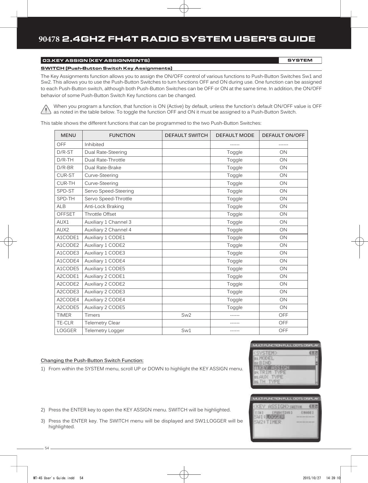
![53TRTRTR90478 2.4GHZ FH4T RADIO SYSTEM USER'S GUIDE1) From within the BIND menu, scroll UP or DOWN to highlight the desired channel youwould like to change the Servo Operating Mode for. Choose from either [ST]:NOR(Steering), [TH]:NOR (Throttle), [A1]:NOR (Auxiliary 1) or [A2]:NOR (Auxiliary 2).02.BIND (BINDING, MODULATION TYPE AND SERVO OPERATING MODE)SYSTEMIMPORTANT INFORMATION ABOUT SERVO OPERATING MODES:If you're using Analog servos in your model, DO NOT use SHR or SSR Servo Operating Mode for those channels. Use the NOR (Normal) Servo Operating Mode with Analog servos. Using SHR or SSR Servo Operating Mode with Analog servos can result in poor performance or even damage to the servos or the receiver! In some cases, the servo may not operate at all.Not all ESCs are compatible with SHR or SSR Servo Operating Modes. If your ESC does not operate correctly, change the Servo Operating Mode to NOR (Normal) for that channel (or channels).SHR and SSR Servo Operating Modes should only be used with Digital servos. While the SHR Servo Operating Mode can be used with any brand of Digital servo, the SSR Servo Operating Mode should ONLY be used with Airtronics SRG Digital servos.2) Press the ENTER key, then scroll UP or DOWN to choose the desired Servo OperatingMode option for that channel.SERVO OPERATING MODE setting range is NOR, SHR and SSR. The default setting is NOR. SSR Operating Mode is not supported when the FH3 or FH3F Modulation Type is selected. No Servo Operating Modes are supported when the FH2 Modulation Type is selected.Binding the Transmitter and Receiver:To Bind the transmitter and receiver, please see the Transmitter and Receiver Binding section on page 16. Prior to Binding the transmitter and receiver, make sure to choose the desired Modulation Type that matches the receiver you're using. Servo Operating Mode can be changed prior to Binding the transmitter and receiver, or after the Binding process.SYSTEMTrm1 - Steering TrimTrm2 - Throttle TrimTrm3 - Steering Dual RateTrm4 - Brake Dual RateSw1 - Telemetry Logger ON/OFFSw2 - Timer ON/OFFDial Knob - Auxiliary 1 Channel 3Auxiliary Lever - Auxiliary 2 Channel 4The Key Assignments function allows you to assign different functions to each of the two Push-Button Switches, the four Trim Switches, the Dial Knob and the Auxiliary Lever. In addition, the ON/OFF behavior of some Push-Button Switch functions can be changed. The Key Assignments function also allows you to change the Direction of Travel and the Trim Resolution of the four Trim Switches and the Rotary Dial. This allows you to fine-tune the movement of the servos when the Trim Switches are pressed and the Rotary Dial is turned. 03.KEY ASSIGN (KEY ASSIGNMENTS)SYSTEMTrim Switch (Trm1) Dial KnobPush-ButtonSwitch (Sw1)Trim Switch (Trm2)Trim Switch (Trm3)Trim Switch (Trm4)Auxiliary LeverPush-Button Switch (Sw2)MT-4S User's Guide.indd 53 2015/10/27 14:39:10](https://usermanual.wiki/Sanwa-Electronic-Instrument-Co/90478.User-Manual-2/User-Guide-2816266-Page-9.png)
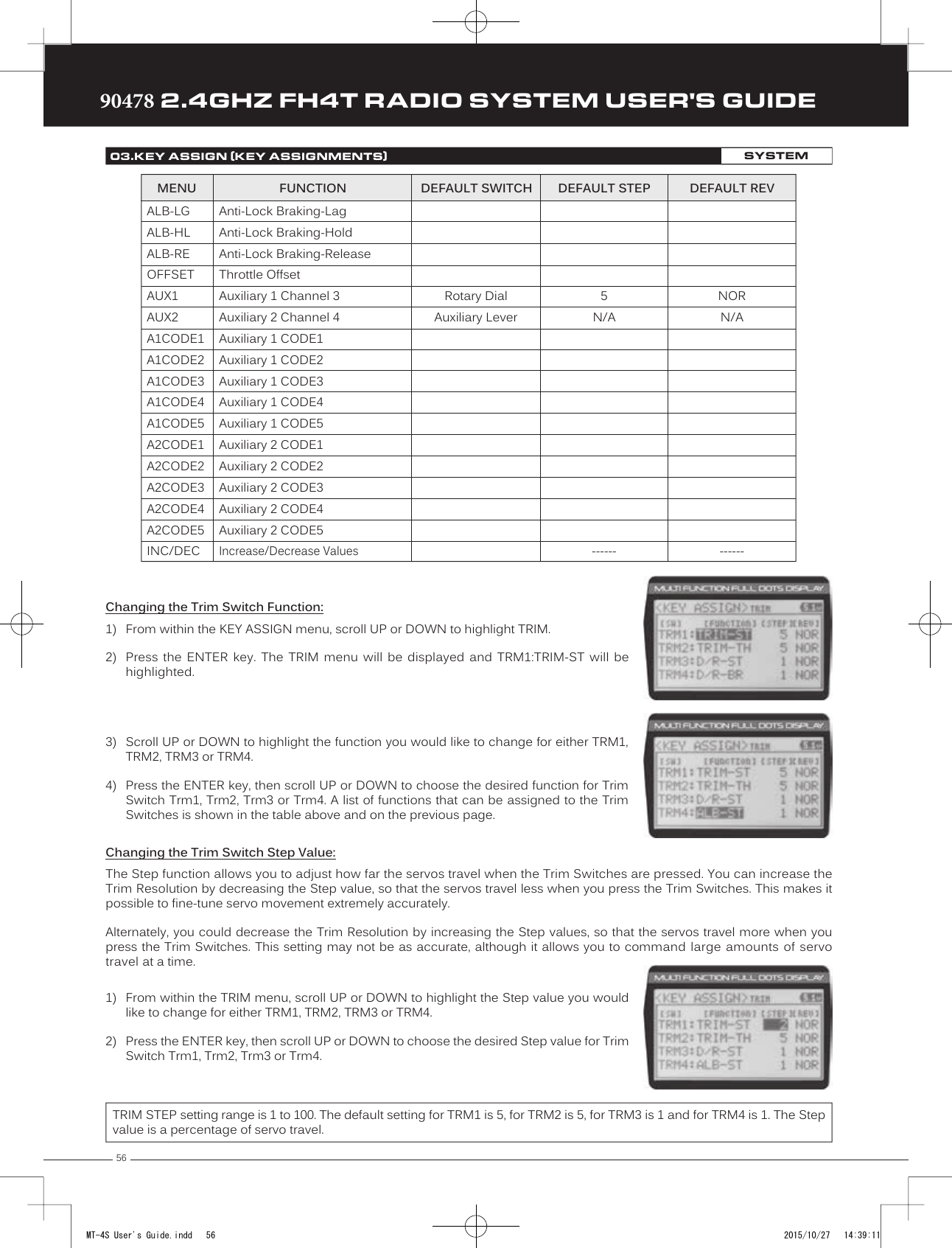
![55TRTRTR90478 2.4GHZ FH4T RADIO SYSTEM USER'S GUIDE4) Scroll UP or DOWN to highlight the function you would like to change for either SW1or SW2.5) Press the ENTER key, then scroll UP or DOWN to choose the desired function for eitherSW1 or SW2. A list of functions that can be assigned to the Push-Button Switches isshown in the table on the previous page.Changing the Switch Mode:Some functions allow you to change how the Push-Button Switch operates. The following Switch Modes are available:TOGGLE - When selected, press the Push-Button Switch to turn the function ON and press the Push-Button Switch a second time to turn the function OFF. See note on previous page. PUSH - When selected, press and HOLD the Push-Button Switch to turn the function ON. When the Push-Button Switch is released, the function will be turned OFF.1) From within the KEY ASSIGN SWITCH menu, scroll DOWN to highlight the MODE youwould like to change for either SW1 or SW2.2) Press the ENTER key, then scroll UP or DOWN to choose the desired Switch Modesetting, either TOGGLE or PUSH.The Switch Mode cannot be changed for all functions. When [MODE] ------, the Push-Button Switch will act as if it were in Toggle Mode.The Key Assignments function allows you to assign different functions to Trim Switches Trm1, Trm2, Trm3 and Trm4, the Rotary Dial and the Auxiliary Lever. This allows you to use the Trim Switches, Rotary Dial and Auxiliary Lever to control those functions while you're driving. In addition, the Direction of Travel (REV) and the Trim Resolution (Step value) of each Trim Switch and the Rotary Dial can be changed. The High and Low Travel Limits and the Direction of Travel of the Auxiliary Lever can be changed, too.This table shows the different functions that can be programmed to the Trim Switches, Rotary Dial and Auxiliary Lever. Table is continued on the next page.03.KEY ASSIGN (KEY ASSIGNMENTS)SYSTEMTRIM, DIAL AND LEVER (Trim Switch, Rotary Dial and Auxiliary Lever Key Assignments)OFFTRIM-STTRIM-THTRIM-A1TRIM-A2D/R-STD/R-THD/R-BRCU-R-STCU-P-STCU-R-THCU-P-THCU-R-BRCU-P-BRSP-ST-FSP-ST-RSP-TH-FSP-TH-RALB-POALB-STMENU FUNCTION DEFAULT SWITCH DEFAULT REVDEFAULT STEPInhibitedTrim-SteeringTrim-ThrottleTrim-Auxiliary 1Trim-Auxiliary 2Dual Rate-SteeringDual Rate-ThrottleDual Rate-BrakeCurve-Rate-SteeringCurve-Point-SteeringCurve-Rate-ThrottleCurve-Point-ThrottleCurve-Rate-BrakeCurve-Point-BrakeSpeed-Steering-ForwardSpeed-Steering-Return to NeutralSpeed-Throttle-ForwardSpeed-Throttle-Return to NeutralAnti-Lock Braking-PointAnti-Lock Braking-StrokeTrm1Trm2Trm3Trm4------5511------NORNORNORNORSYSTEMMT-4S User's Guide.indd 55 2015/10/27 14:39:10](https://usermanual.wiki/Sanwa-Electronic-Instrument-Co/90478.User-Manual-2/User-Guide-2816266-Page-11.png)
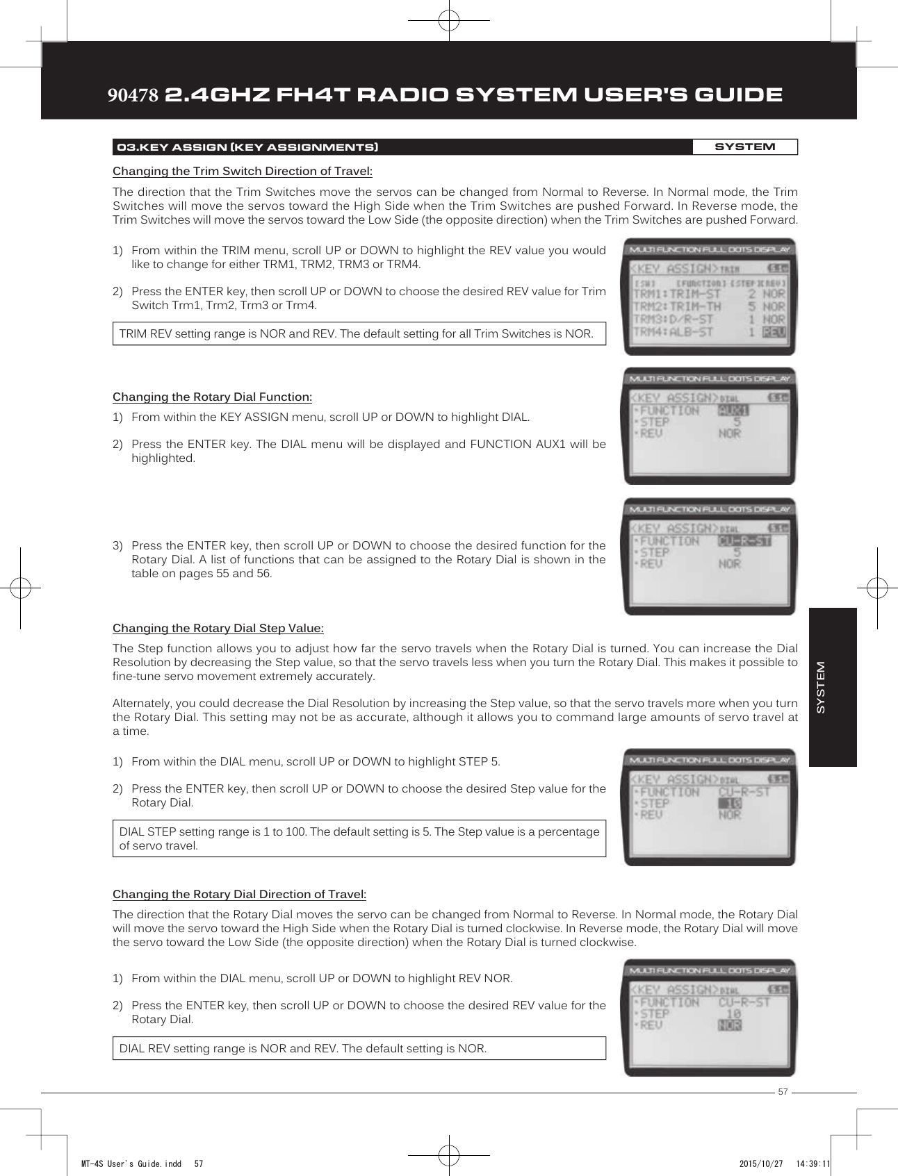
![59TRTRTR90478 2.4GHZ FH4T RADIO SYSTEM USER'S GUIDEChanging the Trim Type:1) From within the SYSTEM menu, scroll UP or DOWN to highlight the TRIM TYPE menu.SYSTEM04.TRIM TYPE (TRIM TYPE)SYSTEMThe Trim Type function allows you choose the way servo Trim and servo End Point Adjustments interact with each other. When you apply Trim to a servo, the Neutral Point of the servo shifts toward the High Side or the Low Side. When you do this, the servo travels less in one direction and more in the other direction because the servo End Points are stationary. In order to balance the servo travel, you would need to manually readjust the servo End Points. Using the Trim Type function allows you to make the servo End Points shift toward the High Side or the Low Side when you apply Trim. This maintains balanced servo travel without the need to manually readjust the servo End Points.The Trim Type function does not effect servo Sub-Trim. It only effects servo Trim that's input using the Trim Switches, Rotary Dial or Auxiliary Lever. Servo Sub-Trim, which is different, always uses Parallel Trim.Two Trim Types are available: CENTER - When Selected, servo End Points are stationary. In order to balance servo travel, you would need to manually readjust the servo End Points, if desired.PARALLEL - When Selected, servo End Points shift toward the High Side or the Low Side automatically when you apply Trim. This maintains balanced servo travel without the need to manually readjust the servo End Points. 2) Press the ENTER key. The TRIM TYPE menu will be displayed and [ST] CENT will behighlighted.3) Scroll UP or DOWN to highlight the desired channel you would like to change the TrimType option for. Choose from either [ST] CENT (Steering), [TH] CENT (Throttle), [AUX1]CENT (Auxiliary 1) or [AUX2] CENT (Auxiliary 2).4) Press the ENTER key, then scroll UP or DOWN to choose the desired Trim Type optionfor that channel.TRIM TYPE setting range is CENT and PARA. The default setting for all channels is CENT.The Auxiliary Type function allows you choose which Auxiliary function is assigned to Auxiliary 1 Channel 3 or Auxiliary 2 Channel 4. One Auxiliary function can be assigned to each Auxiliary Channel and both Auxiliary Channels can be Active and controlled at the same time using different controls. For example, you can control Auxiliary 1 Channel 3 using the Rotary Dial and Auxiliary 2 Channel 4 using the Auxiliary Lever.For details about programming and using each of the Auxiliary functions, in addition to selecting AUX Type Modes, see the Auxiliary 1 Programming section on pages 27 through 33 or the Auxiliary 2 Programming section on pages 34 through 40.05.AUX TYPE (AUXILIARY TYPE)SYSTEMChanging the Auxiliary Function:1) From within the SYSTEM menu, scroll UP or DOWN to highlight the AUX TYPE menu.MT-4S User's Guide.indd 59 2015/10/27 14:39:13](https://usermanual.wiki/Sanwa-Electronic-Instrument-Co/90478.User-Manual-2/User-Guide-2816266-Page-15.png)
![6090478 2.4GHZ FH4T RADIO SYSTEM USER'S GUIDETRTRTR2) Press the ENTER key. The AUX TYPE menu will be displayed and AUX1:STEP AUX will behighlighted.3) Scroll UP or DOWN to highlight the desired channel you would like to change theAuxiliary function for, either AUX1 [TYPE] (Auxiliary 1) or AUX 2 [TYPE] (Auxiliary 2).4) Press the ENTER key, then scroll UP or DOWN to choose the desired Auxiliary functionto be controlled by that channel.AUX TYPE setting range is STEP AUX, POINT AUX, 4WS MIX, MOA MIX and AUX MIX. The default setting for both channels is STEP AUX.The Throttle Type function allows you to change the proportion between Throttle High Side servo travel and Throttle Brake Side servo travel. In the default configuration, the Throttle Type is set to F70:B30. This Throttle Type shifts the throttle Neutral Point toward the Brake Side, resulting in more servo travel toward the High Side and less servo travel toward the Brake Side. Some users may prefer the proportion between Throttle High Side servo travel and Throttle Brake Side servo travel to be balanced (F50:B50). The F70:B30 Throttle Type is most common for general use and racing, while the F50:B50 Throttle Type is most common for Rock Crawling.Changing the Throttle Type:1) From within the SYSTEM menu, scroll UP or DOWN to highlight the TH TYPE menu.2) Press the ENTER key. The TH TYPE menu will be displayed and MODE F70:B30 will behighlighted.3) Press the ENTER key, then scroll UP or DOWN to choose the desired Throttle Typeoption.TH TYPE setting range is F70:B30 and F50:B50. The default setting is F70:B30.05.AUX TYPE (AUXILIARY TYPE)SYSTEM06.TH TYPE (THROTTLE TYPE)SYSTEMTwo Throttle Types are available: F70:B30 - When Selected, the Throttle Neutral Point is shifted toward the Brake Side which provides more High Side servo travel and less Brake Side servo travel. This is most common for general use and racing.F50:B50 - When Selected, the Throttle Neutral Point is centered, which provides the same amount of High Side and Brake Side servo travel. This is most common for Rock Crawling.4) Press the ENTER key. Either Set to F70:B30? NO/YES will be displayed or Set to F50:B50?NO/YES will be displayed.5) Scroll DOWN to highlight YES, then press the ENTER key to Activate the chosen Throttle Type.The current Throttle Type will be displayed on the Top Screen. 7:3 will be displayed to indicate the current Throttle Type is F70:B30 or 5:5 will be displayed to indicate the current Throttle Type is F50:B50.MT-4S User's Guide.indd 60 2015/10/27 14:39:14](https://usermanual.wiki/Sanwa-Electronic-Instrument-Co/90478.User-Manual-2/User-Guide-2816266-Page-16.png)
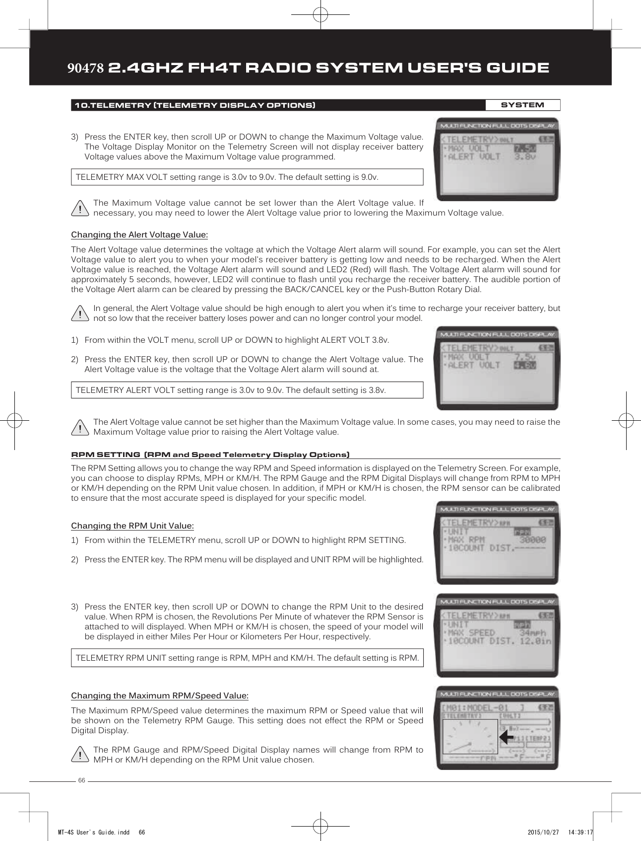
![6490478 2.4GHZ FH4T RADIO SYSTEM USER'S GUIDETRTRTR1) From within the TEMP1 or TEMP2 menu, scroll UP or DOWN to highlight MAX TEMP248ºF (or 120ºC).2) Press the ENTER key, then scroll UP or DOWN to change the Maximum Temperaturevalue. The Temperature Display Monitor on the Telemetry Screen will not displaytemperature values above the Maximum Temperature value programmed.Changing the Maximum Temperature Value:The Maximum Temperature value determines the maximum temperature shown on the [TEMP1] or [TEMP2] Telemetry Screen Temperature Display Monitors. This allows you to calibrate each Temperature Display Monitor to match what the Temperatures Sensor is attached to. This setting does not effect the TEMP1 or TEMP2 Digital Displays.TELEMETRY MAX TEMP setting range is 68ºF to 302ºF (0ºC to 150ºC). The default setting is 248ºF (120ºC).The Maximum Temperature value cannot be set lower than the Alert Temperature value or the Minimum Temperature value. In some cases, you may need to lower the Alert Temperature value prior to lowering the Maximum Temperature value.Changing the Alert Temperature Value:The Alert Temperature value determines the temperature at which the Temperature Alert alarm will sound. For example, you can set an Alert Temperature value for your Nitro engine that will alert you when your engine's cylinder head temperature is getting too hot.When the Alert Temperature value is reached, the Temperature Alert alarm will sound and LED2 (Red) will flash. The Temperature Alert alarm will sound for approximately 5 seconds, however, LED2 will continue to flash until the temperature drops below the Alert Temperature value. The audible portion of the Temperature Alert alarm can be cleared by pressing the BACK/CANCEL key or the Push-Button Rotary Dial. 3) Scroll UP or DOWN to highlight TEMP1 SETTING or TEMP2 SETTING.4) Press the ENTER key. The TEMP1 or TEMP2 menu will be displayed and TEMP UNIT ºFwill be highlighted.5) Press the ENTER key, then scroll UP or DOWN to change the Temperature Unit to thedesired value.TELEMETRY TEMP UNIT setting range is ºF and ºC. The default setting is ºF.10.TELEMETRY (TELEMETRY DISPLAY OPTIONS)SYSTEMChanging the Temperature Unit Value:If desired, the Temperature Unit value can be changed from Fahrenheit to Celsius.1) From within the SYSTEM menu, scroll UP or DOWN to highlight the TELEMETRY menu.2) Press the ENTER key. The TELEMETRY menu will be displayed and TEMP1 SETTING willbe highlighted.The tick marks in the Temperature Display Monitors indicate the current temperature relative to the programmed Maximum and Minimum Temperature values.This section covers both the TEMP1 and TEMP2 menus, since programming each of them is exactly the same. Choose either the TEMP1 or the TEMP2 menu depending on which of the two Temperature Sensor Ports you want to make changes to.MT-4S User's Guide.indd 64 2015/10/27 14:39:16](https://usermanual.wiki/Sanwa-Electronic-Instrument-Co/90478.User-Manual-2/User-Guide-2816266-Page-20.png)
![65TRTRTR90478 2.4GHZ FH4T RADIO SYSTEM USER'S GUIDE1) From within the TEMP1 or TEMP2 menu, scroll UP or DOWN to highlight ALERT TEMP212ºF (or 100ºC).2) Press the ENTER key, then scroll UP or DOWN to change the Alert Temperature value.The Alert Temperature value is the temperature that the Temperature Alert alarm willsound at.TELEMETRY ALERT TEMP setting range is 68ºF to 302ºF (0ºC to 150ºC). The default setting is 212ºF (100ºC).The Alert Temperature value cannot be set higher than the Maximum Temperature value. In addition, the Alert Temperature value cannot be set lower than the Minimum Temperature value. In some cases, you may need to lower the Minimum Temperature value prior to lowering the Alert Temperature value.Changing the Minimum Temperature Value:The Minimum Temperature value determines the Minimum temperature shown on the [TEMP1] or [TEMP2] Telemetry Screen Temperature Display Monitors. This allows you to calibrate each Temperature Display Monitor to match what the Temperatures Sensor is attached to. This does not effect the TEMP1 or TEMP2 Digital Displays.10.TELEMETRY (TELEMETRY DISPLAY OPTIONS)SYSTEM1) From within the TEMP1 or TEMP2 menu, scroll UP or DOWN to highlight MIN TEMP 68ºF(or 20ºC).2) Press the ENTER key, then scroll UP or DOWN to change the Minimum Temperaturevalue. The Temperature Display Monitor on the Telemetry Screen will not displaytemperature values below the Minimum Temperature value programmed.TELEMETRY MIN TEMP setting range is 32ºF to 302ºF (0ºC to 150ºC). The default setting is 68ºF (20ºC).The Minimum Temperature value cannot be set higher than the Alert Temperature value or the Maximum Temperature value. In some cases, you may need to increase these values prior to increasing the Minimum Temperature value.The tick marks in the Temperature Display Monitors indicate the current temperature relative to the programmed Maximum and Minimum Temperature values.The Voltage Setting allows you to change the way receiver battery Voltage information is displayed on the Telemetry Screen and when the Voltage Alert alarm sounds. For example, you can adjust the Voltage value that the receiver battery Low Voltage Alert alarm will sound at to match the type of receiver battery you're using.Changing the Maximum Voltage Value:The Maximum Voltage value determines the maximum receiver battery Voltage that will be shown on the [VOLT] Telemetry Screen Display Monitor. This allows you to calibrate the Voltage Display Monitor to match your model's receiver battery. This setting does not effect the VOLT Digital Display.VOLT SETTING (Receiver Battery Voltage Telemetry Display Options)1) From within the TELEMETRY menu, scroll UP or DOWN to highlight VOLT SETTING.2) Press the ENTER key. The VOLT menu will be displayed and MAX VOLT 9.0v will behighlighted.PRO TIP: We suggest using a value that matches as closely as possible the peaked voltage value of your receiver battery after it's pulled off your charger.SYSTEMMT-4S User's Guide.indd 65 2015/10/27 14:39:16](https://usermanual.wiki/Sanwa-Electronic-Instrument-Co/90478.User-Manual-2/User-Guide-2816266-Page-21.png)
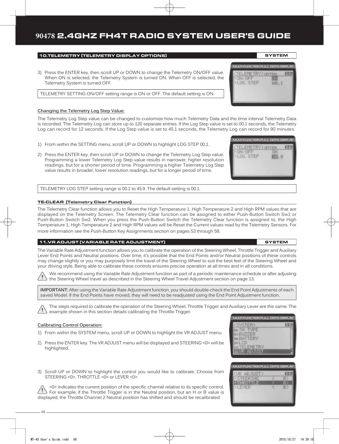
![69TRTRTR90478 2.4GHZ FH4T RADIO SYSTEM USER'S GUIDETo cancel the calibration process, scroll UP or DOWN to highlight NO, then press the ENTER key. You can then return to VR ADJUST menu by pressing the BACK/CANCEL key.8) If desired, repeat steps 3 through 7 to calibrate the remaining controls.11.VR ADJUST (VARIABLE RATE ADJUSTMENT)SYSTEM5) Press the ENTER key a second time. A menu with several position indicators will bedisplayed.6) Move the Steering Wheel, Throttle Trigger or Auxiliary Lever all the way in one direction.Allow the control to return to Neutral, then move the Steering Wheel, Throttle Trigger orAuxiliary Lever all the way in the opposite direction. A series of values and Adjust ok?NO/YES will be displayed.7) Scroll DOWN to highlight YES, then press the ENTER key. Executed will flash, indicatingthat the calibration process is complete.4) With the Steering Wheel, Throttle Trigger or Auxiliary Lever in the Neutral position, pressthe ENTER key. [NEUT] POS <-----> will be displayed.The Auxiliary Lever features a detent to indicate its Neutral position.REFERENCETELEMETRY CONNECTIONS AND MOUNTING REFERENCEOverview:The RX-461 and RX-462 receivers each feature two Temperature Sensor Inputs and one RPM Sensor Input, in addition to the Voltage Sensor built into the receiver. Temperature and RPM Sensors can be installed into your model to give you Temperature and RPM or Speed feedback in real-time displayed on the transmitter's Telemetry Screen.The range of the Telemetry System is approximately 260 feet (80 meters), although the range can vary based on many environmental factors. Use the Telemetry Signal Indicator to determine the quality of the Telemetry Signal.When used with an Airtronics 2.4GHz FH4T Telemetry-capable surface receiver, such as the RX-461 or RX-462, and up to two Temperature Sensors and an RPM Sensor (all available separately), Telemetry Data, such as RPM or Speed, Temperature, and Receiver Voltage can be viewed on the M12 transmitter's Telemetry Screen. This section details connecting the RPM and Temperature Sensors to the RX-461 and/or RX-462 receiver and how to mount those Sensors into your model. For more information about the specifics of either receiver, refer to the User's Guide included with your receiver.For more information about viewing Telemetry Data on the Telemetry Screen, see the TELEMETRY Screen section on pages 14 and 15. For more information about choosing Telemetry options, see the Telemetry Display Options section on pages 63 through 68.Plugging the Telemetry Sensors into the Receiver:1) Carefully pry up and remove the plastic cover from over the Telemetry Sensor Input Ports on the receiver.2) Plug the Telemetry Sensor(s) into their respective Input Ports in the receiver. The Temperature Sensor can be plugged intoeither the TEMP 1 or the TEMP 2 Input Port and the RPM Sensor is plugged into the RPM Input Port. The Sensor Plugs areindexed so they can be plugged in only one way.Make sure to push the Sensor Plugs firmly in place to ensure a good connection. When routing Sensor Wires inside your model, be careful that they cannot come into contact with any moving parts. The Sensor Wires should be securely mounted and protected against damage.In addition, install the dust covers included with your receiver to prevent dirt and debris from getting into any unused Input Ports.MT-4S User's Guide.indd 69 2015/10/27 14:39:18](https://usermanual.wiki/Sanwa-Electronic-Instrument-Co/90478.User-Manual-2/User-Guide-2816266-Page-25.png)