Sanwa Electronic Instrument Co 90490 2.4GHz RADIO CONTROL SYSTEM User Manual Part B
Sanwa Electronic Instrument Co Ltd 2.4GHz RADIO CONTROL SYSTEM Part B
UserManual.wiki
>
Sanwa Electronic Instrument Co
>
90490 User Manual
>
User Manual Part B
Contents
1.
User Manual Part B
2.
User Manual Part A
User Manual Part B
Navigation menu
Upload a User Manual
Namespaces
Wiki Guide
HTML
PDF
Info
Views
User Manual
Discussion / Help
Navigation
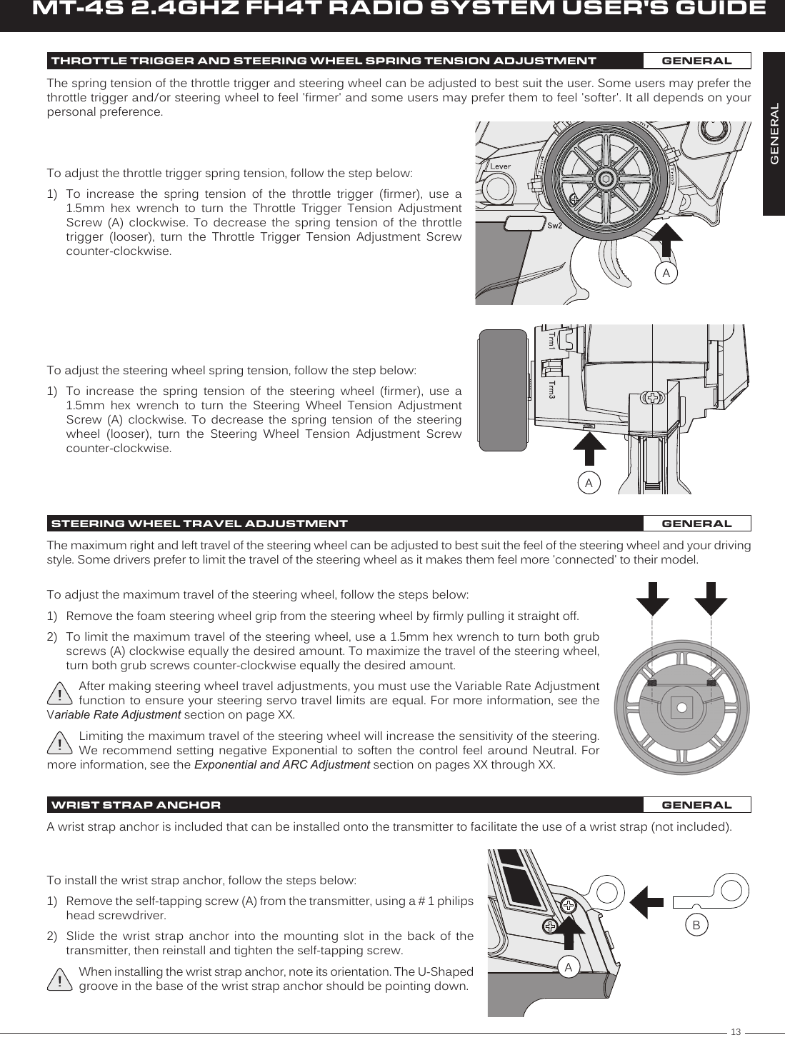
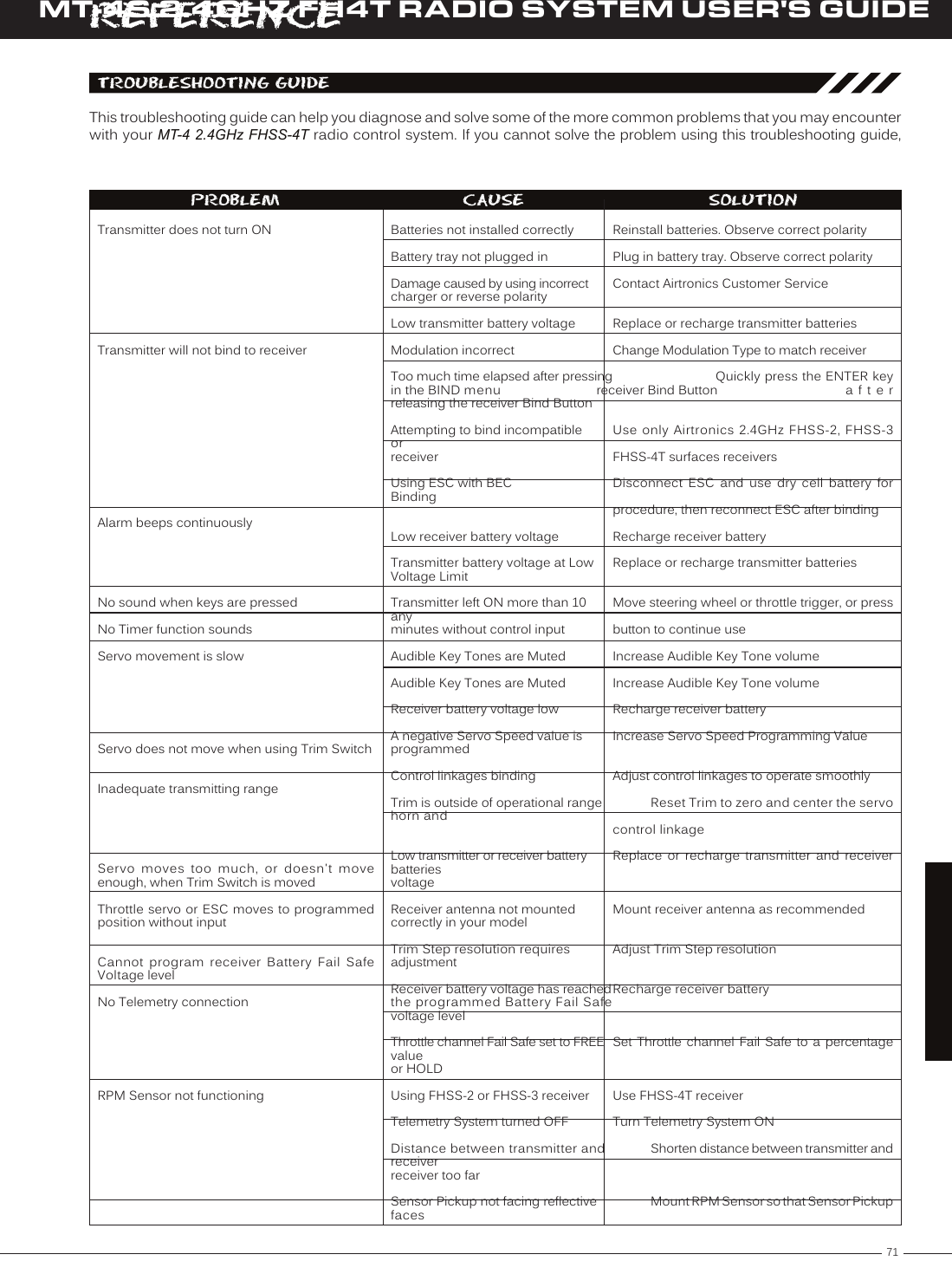
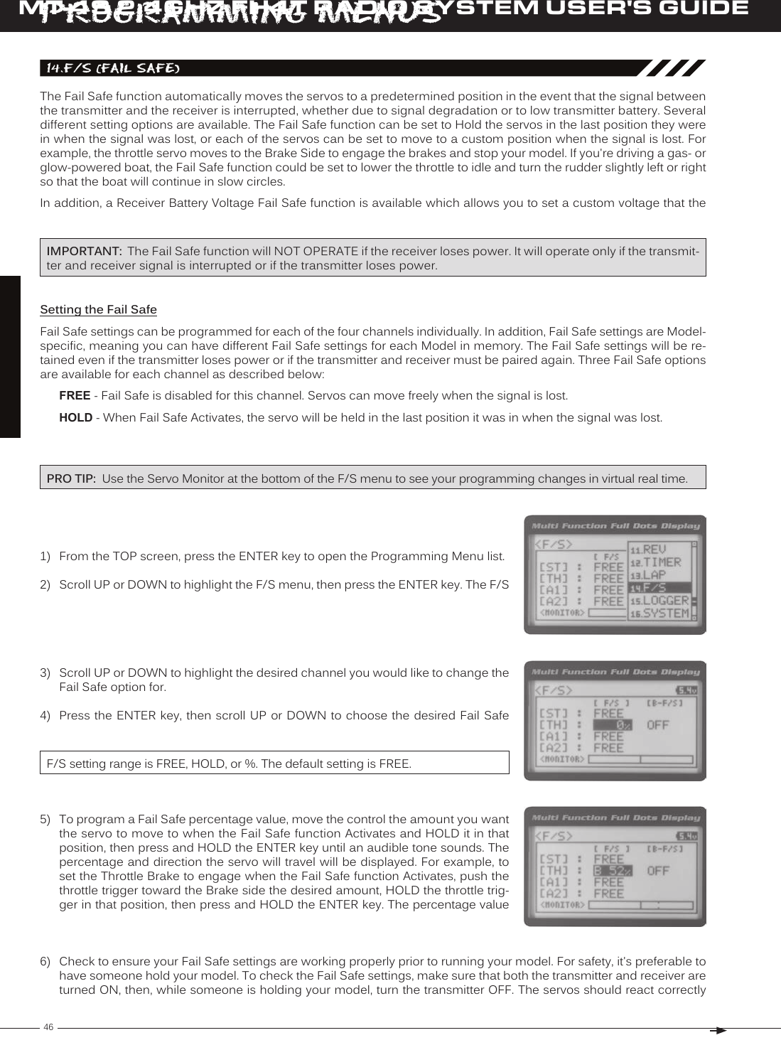
![16MT-4S 2.4GHZ FH4T RADIO SYSTEM USER'S GUIDET RThe Binding function allows you to 'Bind' the transmitter and receiver pair. When new, it is necessary to pair the transmitter and receiver to prevent interference from transmitters operated by other users. This operation is referred to as 'Binding'. Once the Binding process is complete, the setting is remembered even when the transmitter and receiver are turned OFF. Therefore, this procedure usually only needs to be done once.Under some circumstances, the receiver may not operate after turning the transmitter and receiver ON. If this occurs, perform the Binding process again.Before beginning the Binding process, connect your servos and receiver battery pack to the receiver. For more information, see the Receiver Connections and Mounting section on page XX. The transmitter and the receiver should be turned OFF.4) While holding down the Bind Button on the receiver, turn the receiver ON. The Bind LED on the receiver will flash slowly. After approximately 2 seconds, release the Bind Button. The Bind LED on the receiver will continue to flash slowly.Transmitter and Receiver Binding:1) Turn the transmitter ON. The TOP screen will be displayed. Press the ENTER key (Push-Button Rotary Dial) to open the Programming Menu list, then scroll UP or DOWN to highlight the SYSTEM menu.5) Press the ENTER key. The [ENTER] command will begin to flash and the Bind LED on the receiver will flash rapidly, then go out.6) After the Bind LED on the receiver goes out, press the ENTER key a second time. The Bind LED on the receiver will illuminate solid blue and LED 2 on the transmitter will go out, indicating that the Binding procedure is complete and a Telemetry connection has been made.Verify that the Modulation is set to [RF MODE]: FH4T is displayed an that the Servo Operating Mode for each channel is set to NOR. If it isn't, change the Modulation Type to FH4T. If you need to change any of these settings, see the BIND Menu section on pages XX through XX.3) Scroll UP or DOWN to highlight the [ENTER] command. Do not press the ENTER key yet.7) Move the steering wheel and throttle trigger to verify that the servos are operating normally, then press and HOLD the Back/Cancel key to return to the TOP screen.When the Binding procedure is successful, the Bind LED on the receiver and LED 1 on the transmitter will illuminate solid blue. If the Bind LED on the receiver is flashing rapidly or is not illuminated at all, the transmitter and receiver are not paired. In this case, turn both the transmitter and receiver OFF, then repeat the Binding procedure again.bInDInG THE TRAnSMITTER AnD REcEIvER GEnERAlIMPORTANT: This section details Binding the RX-472 4-Channel 2.4GHz FH4T Super Response receiver with the Servo Operating Mode set to Normal mode. If you are Binding an FH2 or FH3 receiver, or if you prefer to change the Servo Operating Mode, see the BIND Menu section on pages XX through XX.2) Press the ENTER key to open the SYSTEM menu, then scroll DOWN to highlight the BIND menu. Press the ENTER key to open the BIND menu.You must complete step 5 below within 10 seconds or the Bind LED will go out, indicating the receiver has timed out. If this occurs, turn the receiver OFF, then repeat step 4.](https://usermanual.wiki/Sanwa-Electronic-Instrument-Co/90490.User-Manual-Part-B/User-Guide-2232371-Page-4.png)
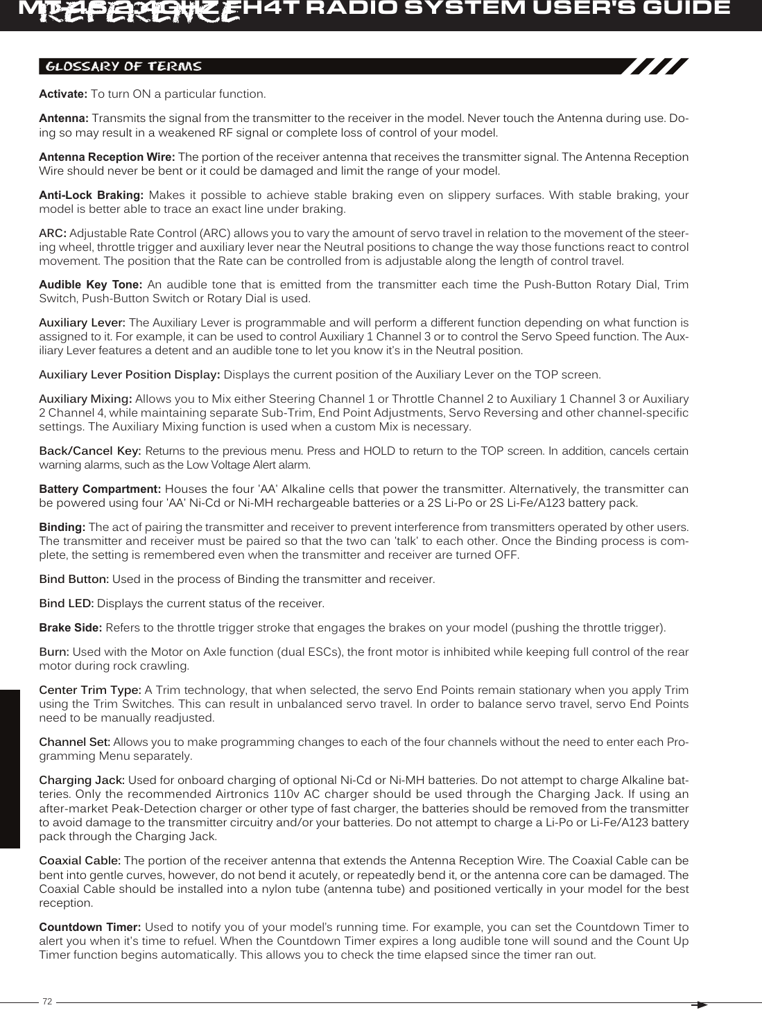
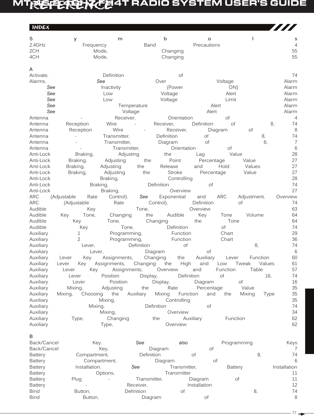
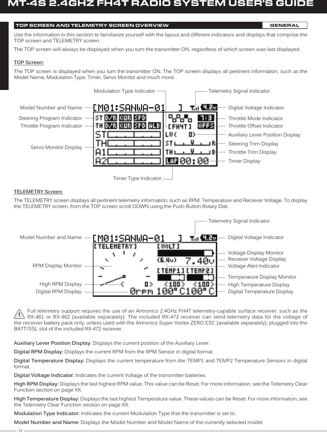
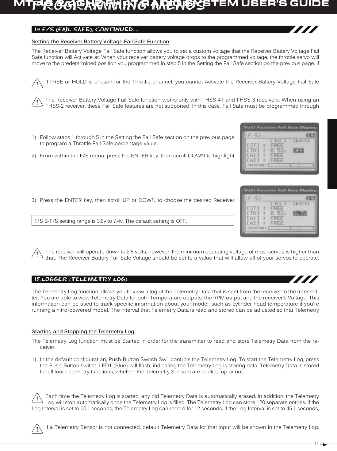
![17T RMT-4S 2.4GHZ FH4T RADIO SYSTEM USER'S GUIDE01.CH-Set (CHannel Set)The Channel Set function allows you to make programming changes to each of the four channels without the need to enter each Programming Menu separately. Essentially, the Channel Set function encompasses the most common pro-gramming options in one convenient location. For example, you can make all of your desired programming changes, such as End Point Adjustment, Exponential, Servo Speed, Fail Safe settings, etc., for each channel, all from within the same menu. To access the various Programming Menus, turn the transmitter ON, then press the ENTER key (Push-Button Rotary Dial). A list of Programming Menus will be displayed along the right side of the screen and the last Programming Menu when the transmitter was turned OFF will be highlighted. The currently highlighted Programming Menu will be displayed in the background.The following Programming Menus are available by scrolling UP or DOWN using the Push-Button Rotary Dial:overview01.CH-SET02.D/R03.EPA04.CURVE05.SPEED06.ALB07.OFFSET08.AUX109.AUX210.TRIM11.REV12.TIMER13.LAP14.F/S15.LOGGER16.SYSTEMChannel SetDual RateEnd Point AdjustmentCurveServo SpeedAnti-Lock BrakingThrottle OffsetAuxiliary 1Auxiliary 2Servo TrimServo ReversingLap and Interval TimersLap TimesFail SafeTelemetry LoggingSystem MenuChange Common Programming Options in One Convenient LocationAdjust Channel Dual RatesAdjust Channel End PointsAdjust Channel Exponential or Adjustable Rate Control (ARC)Slow Down Servo Speed in the Forward and Return to Neutral Direc-tionsProgram the Anti-Lock Braking FunctionProgram the Throttle Offset PositionChoose and Adjust Auxiliary 1 Channel 3 Functions and ProgrammingChoose and Adjust Auxiliary 2 Channel 4 Functions and ProgrammingAdjust Servo Trim and Servo Sub-TrimChange the Direction that the Servos TravelProgram the Lap Timer and the Interval TimerDisplays Current, Past and Best Lap TimesProgram Fail Safe SettingsView Logs of Temperature, Voltage and RPM Telemetry DataAccess the System MenuM E N U MENU NAME MENU DESCRIPTIONPROGRAMMING MENUS1) From the TOP screen, press the ENTER key to open the Programming Menu list.2) Scroll UP or DOWN to highlight the CH-SET menu, then press the ENTER key. The CH-SET menu will be displayed and the cursor will default to [ST].This section details how to use the Channel Set function. For information about programming each of the Program-ming Menus within the CH-SET menu, refer to the specific Programming Menu sections on the pages shown in the table above.PAGE #PG. 19PG. 20PG. 22PG. 23PG. 25PG. 27PG. 28PG. 29PG. 36PG. 42PG. 44PG. 44PG. 47PG. 48PG. 49PG. 513) Scroll DOWN to move the cursor to the channel you would like to make Program-ming Value changes to. Choose from <CH-SET> [ST] (Steering), <CH-SET> [TH] (Throttle), <CH-SET> [A1] (Auxiliary 1) or <CH-SET> [A2] (Auxiliary 2).](https://usermanual.wiki/Sanwa-Electronic-Instrument-Co/90490.User-Manual-Part-B/User-Guide-2232371-Page-5.png)
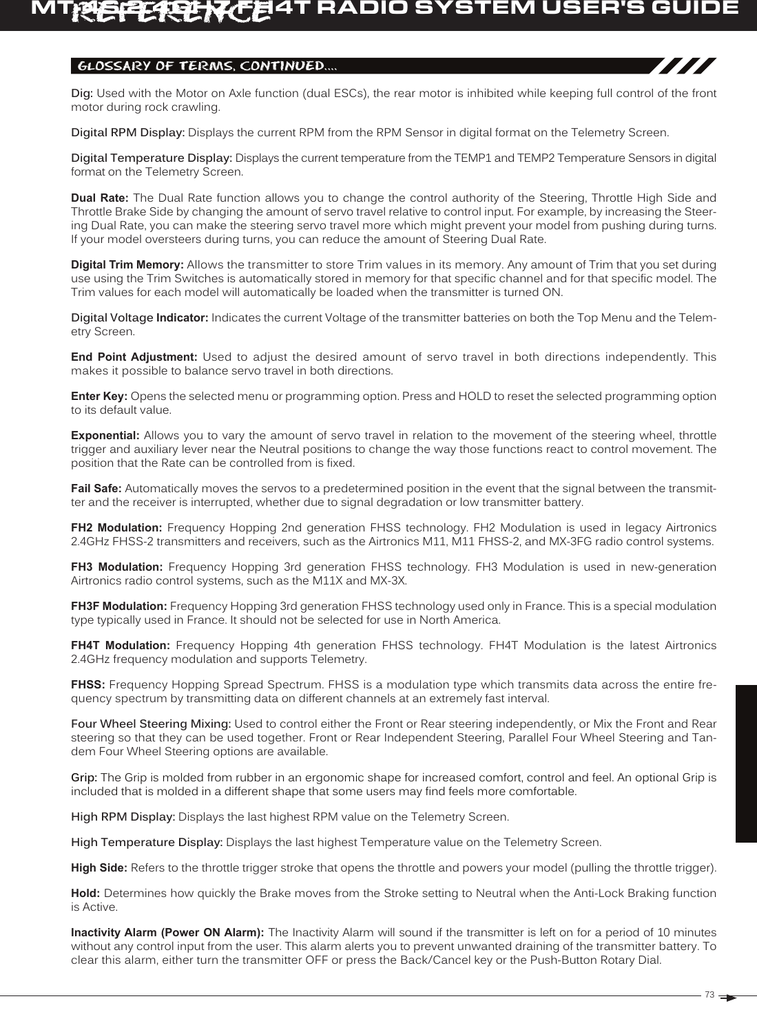
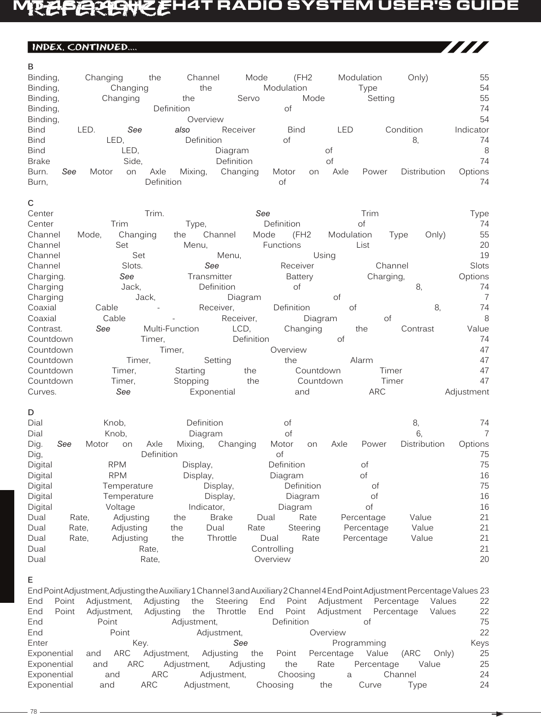
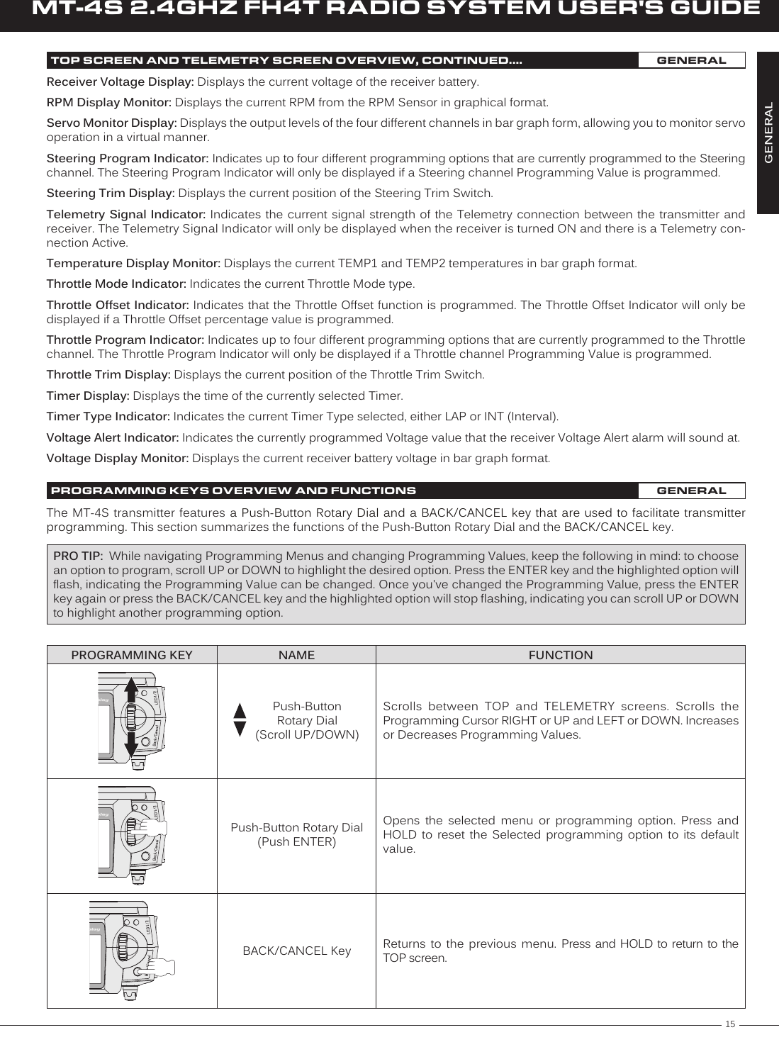
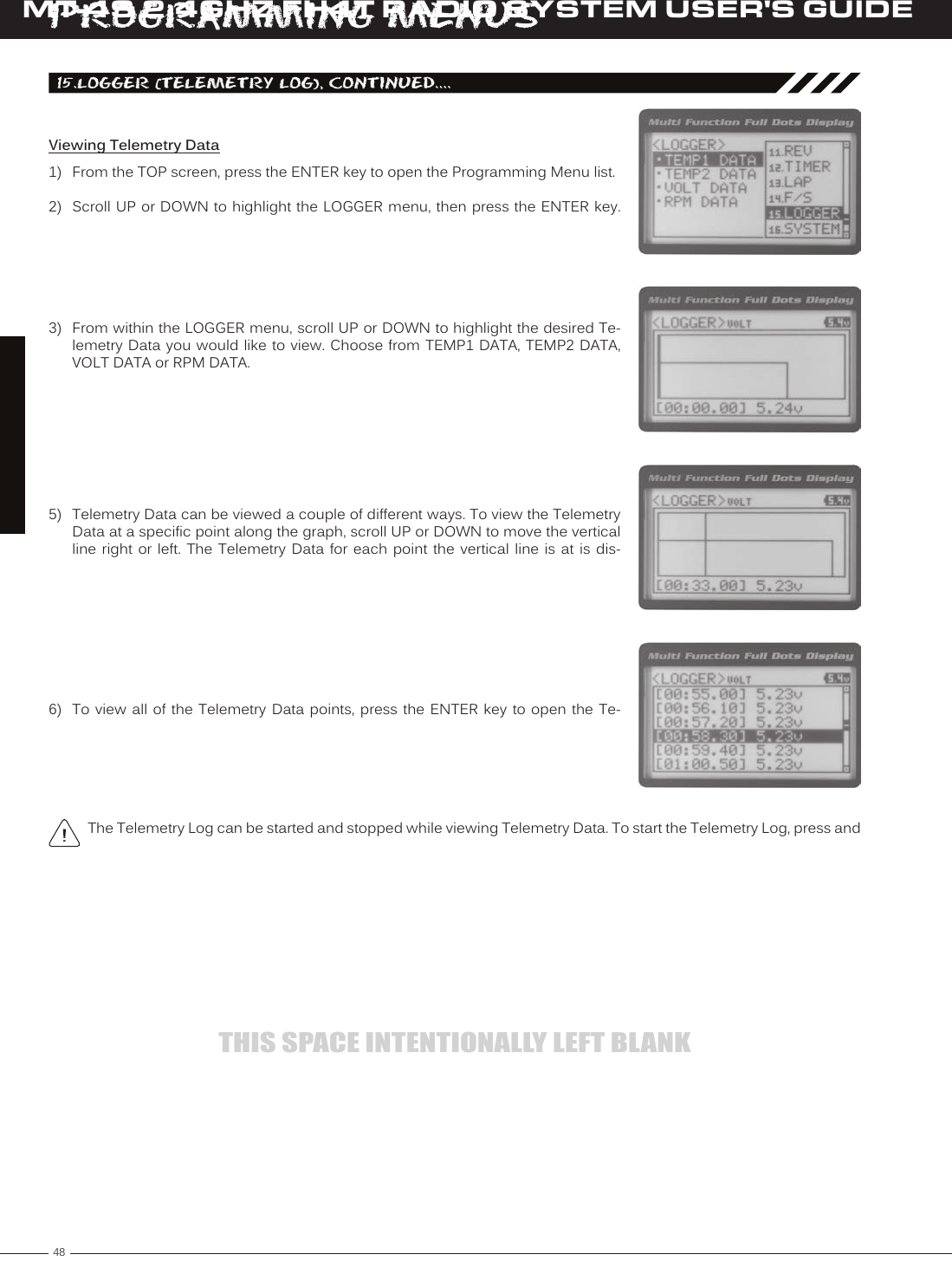
![19T RMT-4S 2.4GHZ FH4T RADIO SYSTEM USER'S GUIDED/R ST RATE setting range is 0% to 100%. The default setting is 100%.3) Press the ENTER key, then scroll UP or DOWN to increase or decrease the Steer-ing Dual Rate percentage value. When the Steering Dual Rate percentage value is decreased, steering servo travel is decreased. When the Steering Dual Rate per-02.d/r (dual rate), Continued....Adjusting the Steering Dual Rate Percentage Value1) From the TOP screen, press the ENTER key to open the Programming Menu list.2) Scroll UP or DOWN to highlight the D/R menu, then press the ENTER key. The D/R [[ProGraMMinG MenuSAdjusting the Throttle Dual Rate Percentage Value1) From within the D/R menu, scroll UP or DOWN to highlight [TH] : RATE 100%.2) Press the ENTER key, then scroll UP or DOWN to increase or decrease the Throttle Dual Rate percentage value. When the Throttle Dual Rate percentage value is de-creased, Throttle High side servo travel is decreased. When the Throttle Dual Rate D/R TH RATE setting range is 0% to 100%. The default setting is 100%.Adjusting the Brake Dual Rate Percentage Value1) From within the D/R menu, scroll UP or DOWN to highlight [BR] : RATE 100%.2) Press the ENTER key, then scroll UP or DOWN to increase or decrease the Brake Dual Rate percentage value. When the Brake Dual Rate percentage value is de-creased, Throttle Brake side servo travel is decreased. When the Brake Dual Rate D/R BR RATE setting range is 0% to 100%. The default setting is 100%.PRO TIP: Use the Servo Monitor at the bottom of the Dual Rate menu to see your programming changes in virtual real Controlling the Dual Rate Function1) By assigning the Steering, Throttle and Brake Dual Rate programming func-tions to one or more of the Trim Switches, Auxiliary Lever or Dial Knob, these functions can be adjusted while driving without accessing the Program-ming Menu. In addition, these functions can be toggled OFF and ON by assigning them to one or more Push-Button Switches. For more information, In the default configuration, the Steering and Throttle Dual Rate program-](https://usermanual.wiki/Sanwa-Electronic-Instrument-Co/90490.User-Manual-Part-B/User-Guide-2232371-Page-7.png)
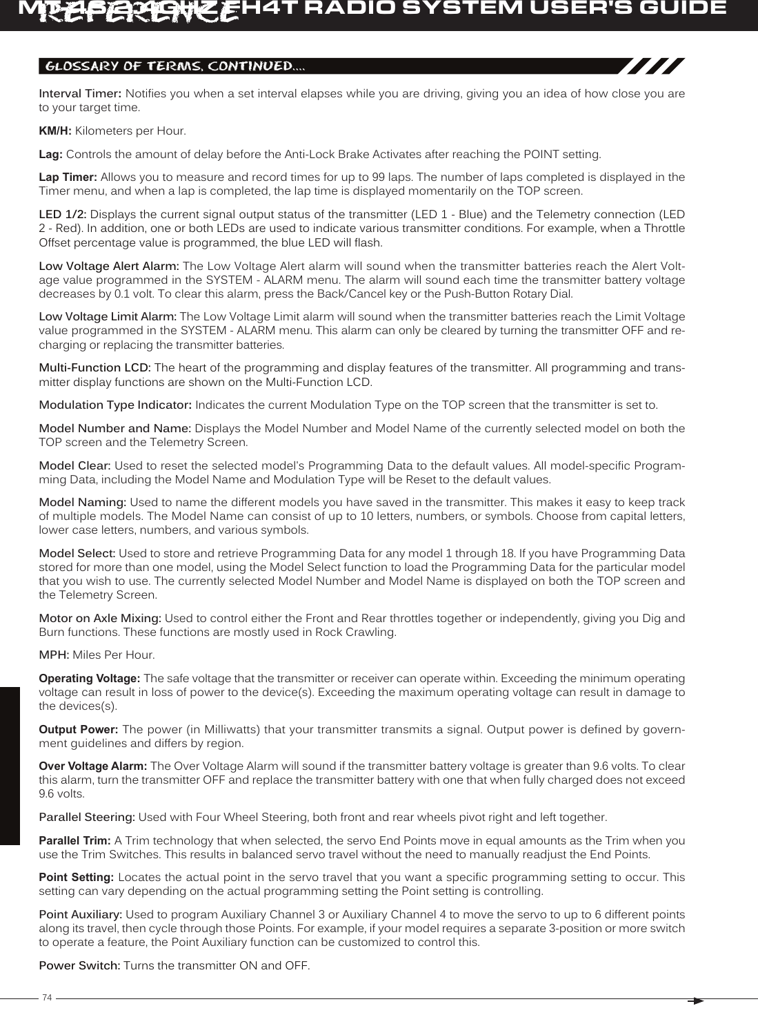
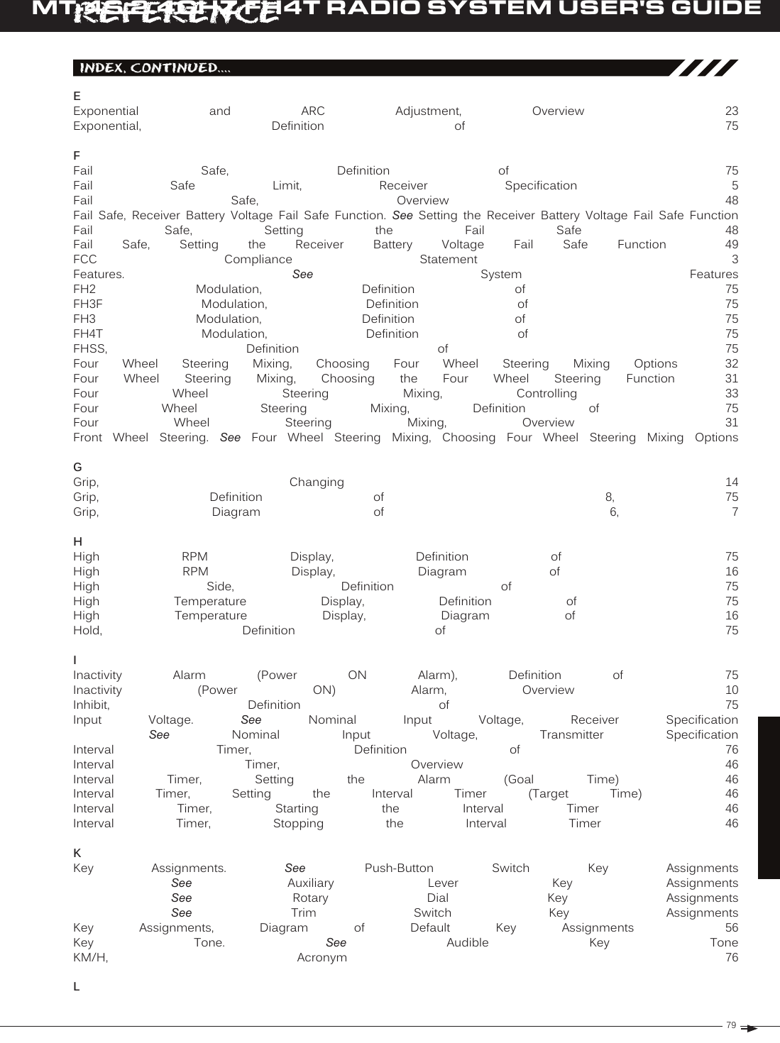
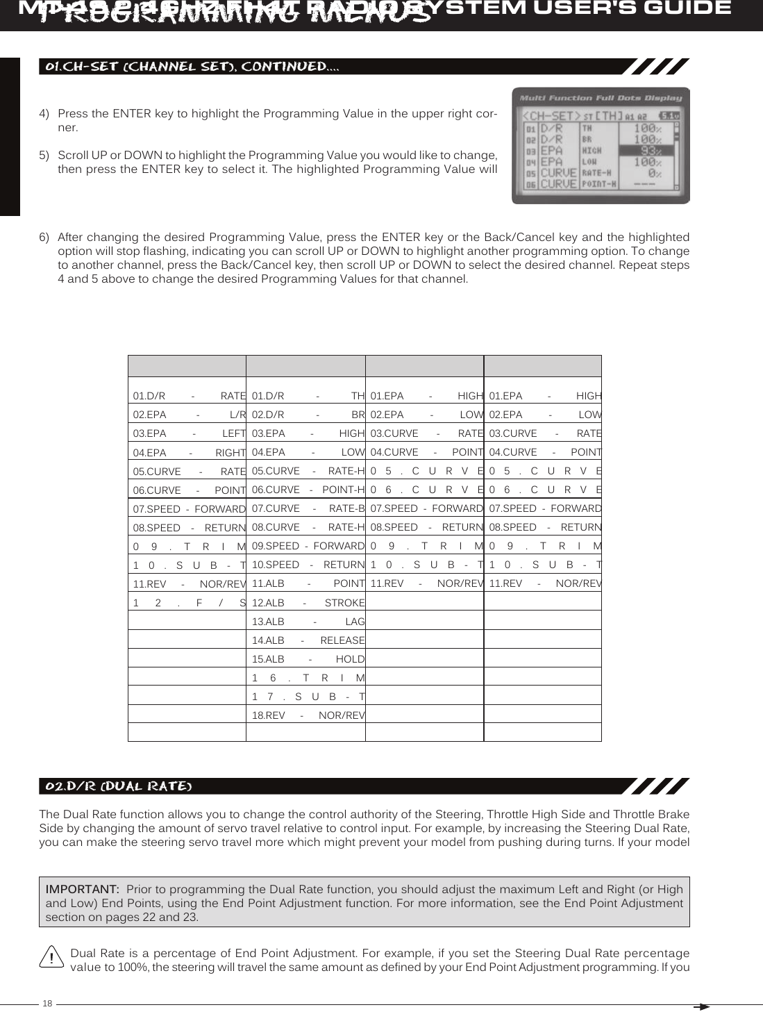
![20MT-4S 2.4GHZ FH4T RADIO SYSTEM USER'S GUIDET R[[ProGraMMinG MenuS03.ePa (end Point adjuStMent)The End Point Adjustment function allows you to adjust servo travel in each direction. This makes it possible to balance servo travel in both directions and set the maximum desired amount of servo travel. For example, on a gas-powered model, if you pull the throttle trigger and the carburetor does not open completely, you can increase the Throttle High End Point Adjustment so that the carburetor opens completely. Another example is with steering. If your model turns sharper to the right than to the left, you can increase the Steering Left End Point Adjustment to balance the steering. The End Point Adjustment function can be adjusted for the Steering channel (Right and Left), the Throttle channel (Throttle High PRO TIP: Use the Servo Monitor at the bottom of the End Point Adjustment menu to see your programming changes in virtual real time. WARNING End Point Adjustment percentage values should not be increased to the point where your linkages and servos bind when moved all the way to the right or left. Binding will cause the servos to 'buzz', resulting in a quicker loss of battery power and eventual damage to the servos.1) From the TOP screen, press the ENTER key to open the Programming Menu list.2) Scroll UP or DOWN to highlight the EPA menu, then press the ENTER key. The Before making End Point Adjustments, the servo horn needs to be centered. Install the servo horn onto the servo, making sure it's as close to being centered as possible, then use the Servo Sub-Trim function to center the servo Adjusting the Steering End Point Adjustment Percentage ValuesYour model’s turning radius can differ from left to right because of variations in linkage, suspension balance, tire diameter, or weight distribution. In such cases, Left Steering servo travel and Right Steering servo travel are adjustable using the EPA ST R setting range is 0% to 150%. The default setting is 100%.4) From within the EPA menu, scroll DOWN to highlight [ST] : EPA R100%. Press the ENTER key, then scroll UP or DOWN to increase or decrease the Steering Right End Point Adjustment percentage value. Increasing the percentage value will increase steering servo travel in that direction and decreasing 3) Press the ENTER key, then scroll UP or DOWN to increase or decrease the Steering Left End Point Adjustment percentage value. Increasing the percentage value will increase steering servo travel in that direction and decreasing the percentage value EPA ST L setting range is 0% to 150%. The default setting is 100%.Adjusting the Throttle End Point Adjustment Percentage ValuesYour model's carburetor may not open completely, or it may open too much and cause the throttle servo to bind. If you're using an Electronic Speed Control, the Electronic Speed Control may not command full power, or the brake may not Steering EPA L/R can be adjusted from within the Channel Set menu. This option changes both Left and Right](https://usermanual.wiki/Sanwa-Electronic-Instrument-Co/90490.User-Manual-Part-B/User-Guide-2232371-Page-8.png)
![21T RMT-4S 2.4GHZ FH4T RADIO SYSTEM USER'S GUIDE[[ProGraMMinG MenuSIf you're using an Electronic Speed Control, the Throttle High and the Throttle Brake End Point Adjustment per-centage values are both generally set to 100%, although the Throttle High direction may need to be increased to 1) From within the EPA menu, scroll UP or DOWN to highlight [TH] : EPA H 100%.2) Press the ENTER key, then scroll UP or DOWN to increase or decrease the Throttle High End Point Adjustment percentage value. Increasing the percentage value will increase Throttle High servo travel in that direction and decreasing EPA TH H setting range is 0% to 150%. The default setting is 100%.EPA TH B setting range is 0% to 150%. The default setting is 100%.3) From within the EPA menu, scroll DOWN to [TH] : EPA B100%. Press the EN-TER key, then scroll UP or DOWN to increase or decrease the Throttle Brake End Point Adjustment percentage value. Increasing the percentage value will in-crease Throttle Brake servo travel in that direction and decreasing Adjusting the Auxiliary 1 Channel 3 and Auxiliary 2 Channel 4 End Point Adjustment Percentage ValuesAuxiliary 1 Channel 3 and Auxiliary 2 Channel 4 can be used for a number of different uses. One of the more common uses would be for the reverse function in a glow-powered monster truck. Often, the transmission only requires a small amount of throw, but the servo binds because of too much servo travel. In such a case, Auxiliary High servo travel and 1) From within the EPA menu, scroll UP or DOWN to highlight [A1] : EPA H 100% or [A2] : EPA H 100%.2) Press the ENTER key, then scroll UP or DOWN to increase or decrease the Aux-iliary High End Point Adjustment percentage value. Increasing the percentage value will increase auxiliary servo travel in that direction and decreasing the EPA A1 H and EPA A2 H setting range is 0% to 150%. The default setting is 100%.EPA A1 L and EPA A2 L setting range is 0% to 150%. The default setting is 100%.3) From within the EPA menu, scroll UP or DOWN to highlight [A1] : EPA L100% or [A2] : EPA L100%. Press the ENTER key, then scroll UP or DOWN to increase or decrease the Auxiliary Low End Point Adjustment percentage value. Increas-ing the percentage value will increase auxiliary servo travel in that direction and 04.Curve (eXPonential and arC adjuStMent)The Exponential and Adjustable Rate Control (ARC) functions allow you to vary the amount of servo travel in relation to the movement of the steering wheel, throttle trigger and auxiliary lever near the Neutral positions to change the way those functions react to control movement. Decreasing the Exponential or Adjustable Rate Control percentage values will soften the control feel around Neutral and increasing the Exponential or Adjustable Rate Control percentage values will heighten the control feel around Neutral. Using a lower negative value allows for smoother control. Using a higher positive value may result in more 'twitchy' control response. The Exponential and Adjustable Rate Control functions can be adjusted for the Steering channel, the Throttle channel (Throttle High and Throttle Brake), Auxiliary 1 Channel 3 and](https://usermanual.wiki/Sanwa-Electronic-Instrument-Co/90490.User-Manual-Part-B/User-Guide-2232371-Page-9.png)
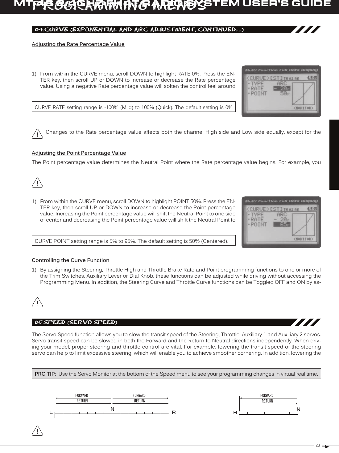
![22MT-4S 2.4GHZ FH4T RADIO SYSTEM USER'S GUIDET R[[ProGraMMinG MenuS04.Curve (eXPonential and arC adjuStMent, Continued....)Choosing the ChannelExponential or Adjustable Rate Control percentage values can be adjusted from Mild through Linear to Quick to allow you to set the most effective control response for your model. For example, if your model over-steers, reduce the Steering Exponential or Adjustable Rate Control percentage value, and if your model under-steers, increase the Steering Exponen-tial or Adjustable Rate Control percentage value. As another example, reduce the Throttle Exponential or Adjustable Rate Control percentage value on a slippery track or with a model that has a higher-torque motor or engine, and increase the The Exponential and Adjustable Rate Control functions work the same, except the Exponential Rate percentage value is programmed from a fixed Neutral Point of 50% and the Adjustable Rate Control Rate percentage value is 1) From the TOP screen, press the ENTER key to open the Programming Menu list.2) Scroll UP or DOWN to highlight the CURVE menu, then press the ENTER key. The 3) Scroll DOWN to move the cursor to the channel you would like to make Program-ming Value changes to. Choose from <CURVE> [ST] (Steering), <CURVE> [TH] Choosing the Curve Type1) Press the ENTER key to highlight TYPE EXP. Press the ENTER key a second time, then scroll UP or DOWN to choose the desired Curve Type. If you are programming the Curve function for the Throttle channel, you have the option of adjusting the CURVE TYPE setting range is EXP and ARC. The default setting is EXP.](https://usermanual.wiki/Sanwa-Electronic-Instrument-Co/90490.User-Manual-Part-B/User-Guide-2232371-Page-10.png)
![24MT-4S 2.4GHZ FH4T RADIO SYSTEM USER'S GUIDET R[[ProGraMMinG MenuS3) Scroll UP or DOWN to highlight the desired channel you would like to change the Forward Speed value for. Choose from either [ST] : FORWARD 0 (Steering), [TH] : FORWARD 0 (Throttle), [A1] : FORWARD 0 (Auxiliary 1) or [A2] : FORWARD 0 4) Press the ENTER key, then scroll DOWN to decrease servo Speed in the Forward direction. Decreasing the Forward Speed value will cause the servo transit time SPEED FORWARD setting range is -100 to 0. The default setting is 0 (Normal Adjusting the Return to Neutral Speed Value1) From within the SPEED menu, scroll UP or DOWN to highlight the desired chan-nel you would like to change the Return to Neutral Speed value for. Choose from either [ST] : RETURN 0 (Steering), [TH] : RETURN 0 (Throttle), [A1] : RETURN 0 2) Press the ENTER key, then scroll DOWN to decrease servo Speed in the Return to Neutral direction. Decreasing the Return to Neutral Speed value will cause the SPEED RETURN setting range is -100 to 0. The default setting is 0 (Normal Speed).Adjusting the Forward Speed Value1) From the TOP screen, press the ENTER key to open the Programming Menu list.2) Scroll UP or DOWN to highlight the SPEED menu, then press the ENTER key. The 05.SPeed (Servo SPeed), Continued....Controlling the Servo Speed Function1) By assigning the Steering and Throttle Forward and Return to Neutral Speed programming functions to one or more of the Trim Switches, Auxiliary Lever or Dial Knob, these functions can be adjusted while driving without accessing the Programming Menu. In addition, the Steering Speed and Throttle Speed functions can be Toggled OFF and ON by IMPORTANT: Throttle Servo Speed affects only the Throttle High Side. The Throttle Brake Side is unaffected. See Throttle diagram on previous page.](https://usermanual.wiki/Sanwa-Electronic-Instrument-Co/90490.User-Manual-Part-B/User-Guide-2232371-Page-12.png)
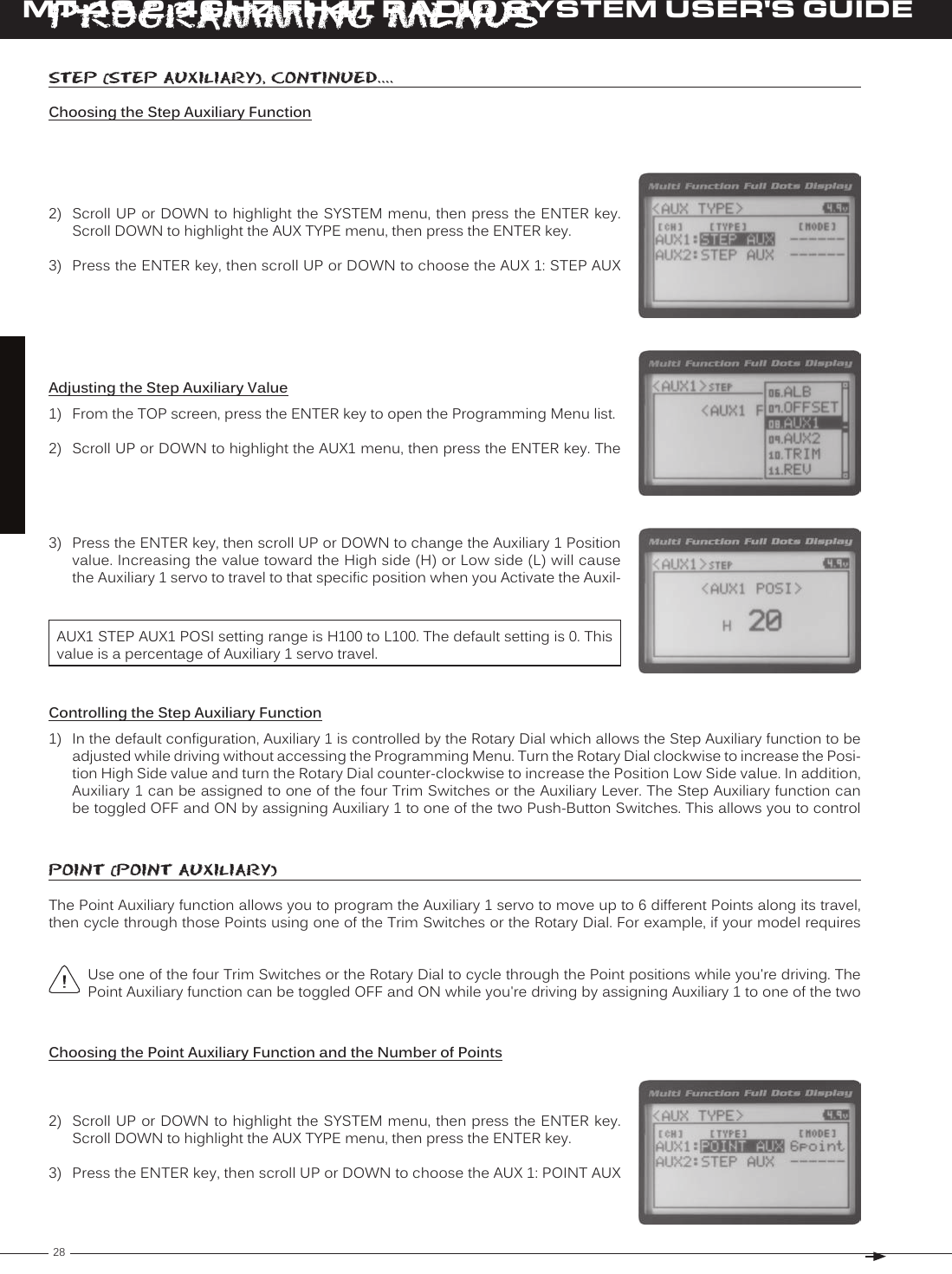
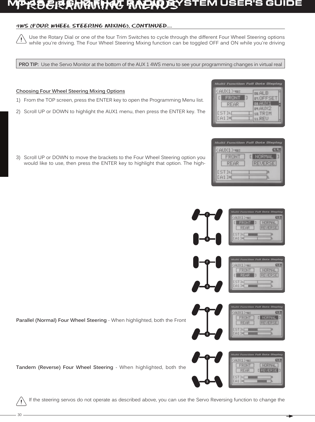
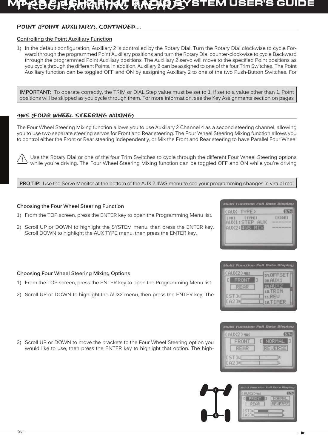
![29T RMT-4S 2.4GHZ FH4T RADIO SYSTEM USER'S GUIDE[[ProGraMMinG MenuSChoosing the Point Auxiliary Function and the Number of Points, Continued....4) From within the AUX TYPE menu, scroll DOWN to highlight [MODE] 6 POINT. Press the ENTER key, then scroll UP or DOWN to choose the desired number of AUX TYPE POINT setting range is 2point to 6point. The default setting is 6point.Adjusting the Point Auxiliary Values1) From the TOP screen, press the ENTER key to open the Programming Menu list.2) Scroll UP or DOWN to highlight the AUX1 menu, then press the ENTER key. The 3) Scroll UP or DOWN to move the brackets to the Point you would like to change, then press the ENTER key to highlight that Point.4) Press the ENTER key, then scroll UP or DOWN to change the Point value. Increas-ing the Point value toward the High side (H) or Low side (L) will cause the Auxil-iary 1 servo to travel to that specific position when you cycle through the various Points.AUX1 POINT setting range is H100 to L100. The default setting for Point 1 is L100, for Point 2 is L60, for Point 3 is L20, for Point 4 is H20, for Point 5 is H60, and for Point 6 is H100. These values are a percentage of Auxiliary 1 servo travel. Controlling the Point Auxiliary Function1) In the default configuration, Auxiliary 1 is controlled by the Rotary Dial. Turn the Rotary Dial clockwise to cycle For-ward through the programmed Point Auxiliary positions and turn the Rotary Dial counter-clockwise to cycle Backward through the programmed Point Auxiliary positions. The Auxiliary 1 servo will move to the specified Point positions as you cycle through the different Points. In addition, Auxiliary 1 can be assigned to one of the four Trim Switches. The Point Auxiliary function can be toggled OFF and ON by assigning Auxiliary 1 to one of the two Push-Button Switches. For IMPORTANT: To operate correctly, the TRIM or DIAL Step value must be set to 1. If set to a value other than 1, Point positions will be skipped as you cycle through them. For more information, see the Key Assignments section on pages 4wS (four wHeel SteerinG MiXinG)The Four Wheel Steering Mixing function allows you to use Auxiliary 1 Channel 3 as a second steering channel, allowing you to use two separate steering servos for Front and Rear steering. The Four Wheel Steering Mixing function allows you to control either the Front or Rear steering independently, or Mix the Front and Rear steering to have Parallel Four Wheel 2) Scroll UP or DOWN to highlight the SYSTEM menu, then press the ENTER key. Scroll DOWN to highlight the AUX TYPE menu, then press the ENTER key.Choosing the Four Wheel Steering Function](https://usermanual.wiki/Sanwa-Electronic-Instrument-Co/90490.User-Manual-Part-B/User-Guide-2232371-Page-17.png)
![33T RMT-4S 2.4GHZ FH4T RADIO SYSTEM USER'S GUIDE[[ProGraMMinG MenuSChoosing the Auxiliary Mixing Function and the Mixing Type1) From the TOP screen, press the ENTER key to open the Programming Menu list.2) Scroll UP or DOWN to highlight the SYSTEM menu, then press the ENTER key. Scroll DOWN to highlight the AUX TYPE menu, then press the ENTER key.4) From within the AUX TYPE menu, scroll DOWN to highlight [MODE] ST-mix. Press the ENTER key, then scroll UP or DOWN to choose the desired Mixing type you AUX TYPE MIX setting range is ST-mix and TH-mix. The default setting is ST-mix.Adjusting the Rate Percentage Value1) From the TOP screen, press the ENTER key to open the Programming Menu list.2) Scroll UP or DOWN to highlight the AUX1 menu, then press the ENTER key. The 3) Press the ENTER key, then scroll UP or DOWN to change the Rate percentage value. Decreasing the Rate percentage value will reduce the amount the Auxiliary 1 servo travels relative to the Steering servo or Throttle servo and increasing the Rate percentage value will increase the amount the Auxiliary 1 servo travels AUX1 AUX MIX RATE setting range is 100% to 0%. The default setting is 100%. This Mix is Linear. For example, if the Rate percentage value is set to 100%, the Auxiliary 1 servo will travel the same amount as the Steering servo. Additionally, if the Rate percentage value is set to 50%, the Auxiliary 1 servo will travel half the amount as the Steering servo.The Master channel (either Steering Channel 1 or Throttle Channel 2) always controls the Slave channel (Auxil-Controlling the Auxiliary Mixing Function1) In the default configuration, Auxiliary 1 is controlled by the Rotary Dial. Turn the Rotary Dial clockwise to increase the Rate percentage value and turn the Rotary Dial counter-clockwise to decrease the Rate percentage value. In addition, the Auxiliary Mixing Rate function can be assigned to one of the four Trim Switches or the Auxiliary Lever. The Auxiliary Mixing function can be toggled OFF and ON by assigning Auxiliary 1 to one of the two Push-Button Switches. For auX MiX (auXiliary MiXinG), Continued....In the default configuration, the Auxiliary 1 servo will travel in the same direction as the Steering servo or Throttle servo. To apply the Mix in the opposite direction, change the Servo Reversing value of Auxiliary 1 Channel 3. For Remember that you are able to independently adjust the Auxiliary 1 Channel 3 Dual Rate, Exponential, Sub-Trim,](https://usermanual.wiki/Sanwa-Electronic-Instrument-Co/90490.User-Manual-Part-B/User-Guide-2232371-Page-21.png)
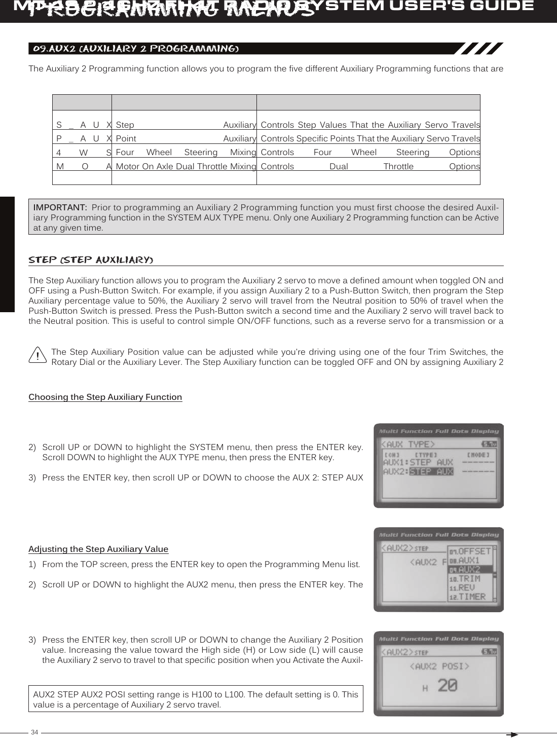
![35T RMT-4S 2.4GHZ FH4T RADIO SYSTEM USER'S GUIDE[[ProGraMMinG MenuSControlling the Step Auxiliary Function1) In the default configuration, Auxiliary 2 is controlled by the Rotary Dial which allows the Step Auxiliary function to be adjusted while driving without accessing the Programming Menu. Turn the Rotary Dial clockwise to increase the Posi-tion High Side value and turn the Rotary Dial counter-clockwise to increase the Position Low Side value. In addition, Auxiliary 2 can be assigned to one of the four Trim Switches or the Auxiliary Lever. The Step Auxiliary function can be toggled OFF and ON by assigning Auxiliary 2 to one of the two Push-Button Switches. This allows you to control SteP (SteP auXiliary), Continued....Point (Point auXiliary)The Point Auxiliary function allows you to program the Auxiliary 2 servo to move up to 6 different Points along its travel, then cycle through those Points using one of the Trim Switches or the Rotary Dial. For example, if your model requires Use one of the four Trim Switches or the Rotary Dial to cycle through the Point positions while you're driving. The Point Auxiliary function can be toggled OFF and ON while you're driving by assigning Auxiliary 2 to one of the two 2) Scroll UP or DOWN to highlight the SYSTEM menu, then press the ENTER key. Scroll DOWN to highlight the AUX TYPE menu, then press the ENTER key.3) Press the ENTER key, then scroll UP or DOWN to choose the AUX 2: POINT AUX Choosing the Point Auxiliary Function and the Number of Points4) From within the AUX TYPE menu, scroll DOWN to highlight [MODE] 6 POINT. Press the ENTER key, then scroll UP or DOWN to choose the desired number of AUX TYPE POINT setting range is 2point to 6point. The default setting is 6point.Adjusting the Point Auxiliary Values1) From the TOP screen, press the ENTER key to open the Programming Menu list.2) Scroll UP or DOWN to highlight the AUX1 menu, then press the ENTER key. The 3) Scroll UP or DOWN to move the brackets to the Point you would like to change, then press the ENTER key to highlight that Point.4) Press the ENTER key, then scroll UP or DOWN to change the Point value. Increas-ing the Point value toward the High side (H) or Low side (L) will cause the Auxil-iary 2 servo to travel to that specific position when you cycle through the various Points.AUX2 POINT setting range is H100 to L100. The default setting for Point 1 is L100, for Point 2 is L60, for Point 3 is L20, for Point 4 is H20, for Point 5 is H60, and for Point 6 is H100. These values are a percentage of Auxiliary 2 servo travel.](https://usermanual.wiki/Sanwa-Electronic-Instrument-Co/90490.User-Manual-Part-B/User-Guide-2232371-Page-23.png)
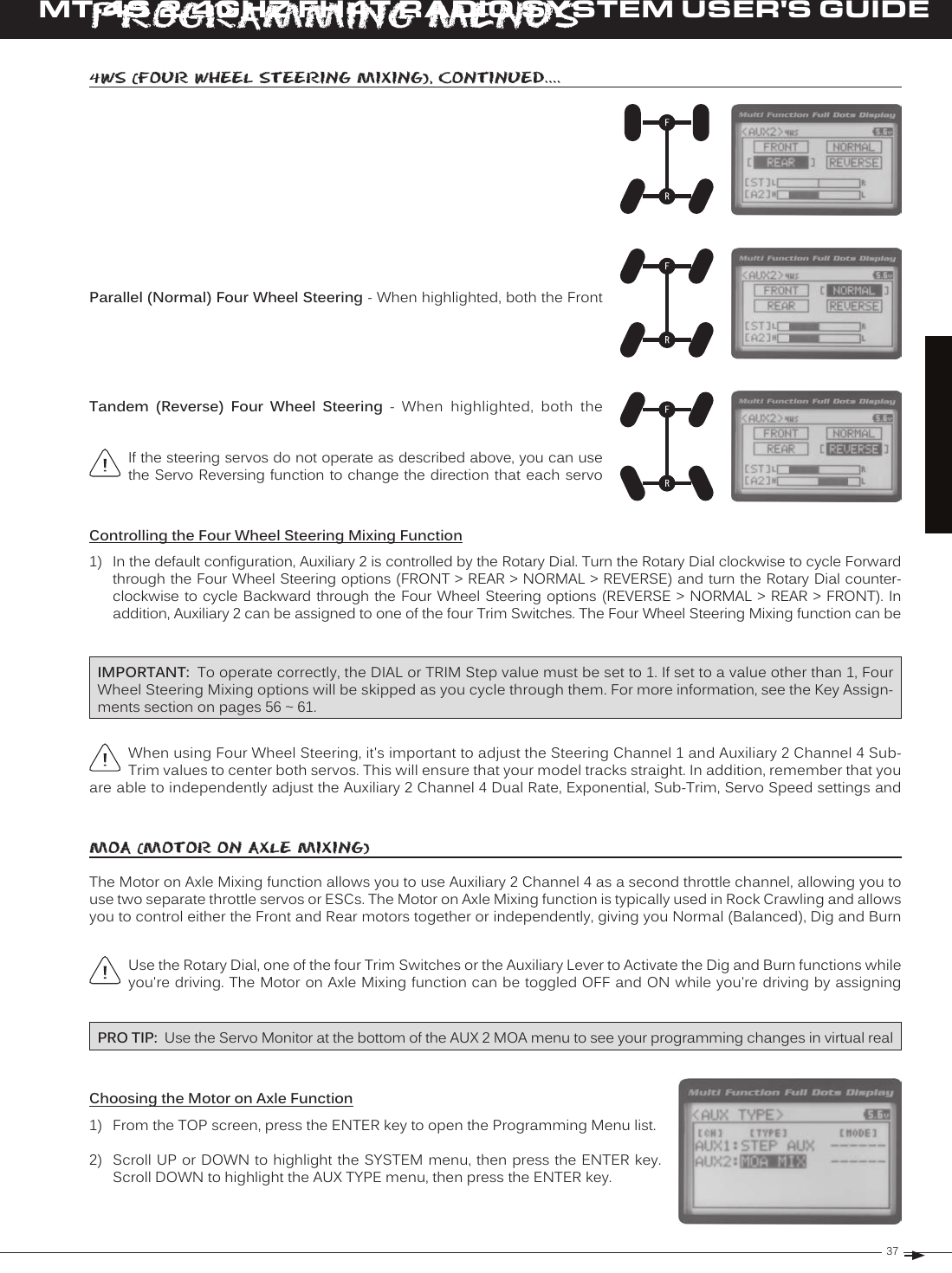
![39T RMT-4S 2.4GHZ FH4T RADIO SYSTEM USER'S GUIDEauX MiX (auXiliary MiXinG)The Auxiliary Mixing function allows you to Mix either Steering Channel 1 or Throttle Channel 2 to Auxiliary 2 Channel 4, while maintaining separate Sub-Trim, End Point Adjustments, Servo Reversing and other channel-specific settings. The Auxiliary Mixing function is used when a custom Mix is necessary. For example, if your monster truck features dual Front steering servos, instead of using a Y-Harness to join the two steering servos together, you can use Steering Mixing to operate both steering servos together and still be able to make adjustments to each servo separately. In addition, if The Auxiliary Mixing Rate percentage value can be adjusted while you're driving using one of the four Trim Switches, the Rotary Dial or the Auxiliary Lever. The Auxiliary Mixing function can be toggled OFF and ON while PRO TIP: Use the Servo Monitor at the bottom of the AUX 2 AUX MIX menu to see your programming changes in virtual real time. Choosing the Auxiliary Mixing Function and the Mixing Type1) From the TOP screen, press the ENTER key to open the Programming Menu list.2) Scroll UP or DOWN to highlight the SYSTEM menu, then press the ENTER key. Scroll DOWN to highlight the AUX TYPE menu, then press the ENTER key.4) From within the AUX TYPE menu, scroll DOWN to highlight [MODE] ST-mix. Press the ENTER key, then scroll UP or DOWN to choose the desired Mixing type you AUX TYPE MIX setting range is ST-mix and TH-mix. The default setting is ST-mix.Adjusting the Rate Percentage Value1) From the TOP screen, press the ENTER key to open the Programming Menu list.2) Scroll UP or DOWN to highlight the AUX2 menu, then press the ENTER key. The 3) Press the ENTER key, then scroll UP or DOWN to change the Rate percentage value. Decreasing the Rate percentage value will reduce the amount the Auxiliary 2 servo travels relative to the Steering servo or Throttle servo and increasing the Rate percentage value will increase the amount the Auxiliary 2 servo travels AUX2 AUX MIX RATE setting range is 100% to 0%. The default setting is 100%. This Mix is Linear. For example, if the Rate percentage value is set to 100%, the Auxiliary 2 servo will travel the same amount as the Steering servo. Additionally, if the Rate percentage value is set to 50%, the Auxiliary 2 servo will travel half the amount as the Steering servo.The Master channel (either Steering Channel 1 or Throttle Channel 2) always controls the Slave channel (Auxil-[[ProGraMMinG MenuS](https://usermanual.wiki/Sanwa-Electronic-Instrument-Co/90490.User-Manual-Part-B/User-Guide-2232371-Page-27.png)
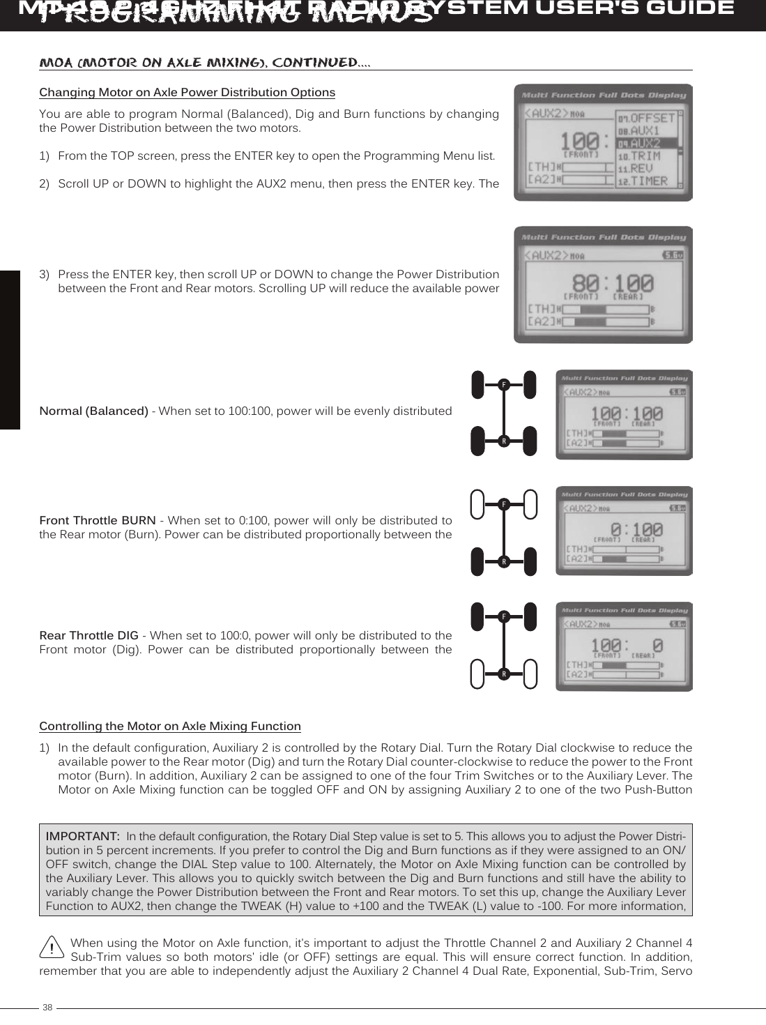
![40MT-4S 2.4GHZ FH4T RADIO SYSTEM USER'S GUIDET RauX MiX (auXiliary MiXinG), Continued....Controlling the Auxiliary Mixing Function1) In the default configuration, Auxiliary 2 is controlled by the Rotary Dial. Turn the Rotary Dial clockwise to increase the Rate percentage value and turn the Rotary Dial counter-clockwise to decrease the Rate percentage value. In addition, the Auxiliary Mixing Rate function can be assigned to one of the four Trim Switches or the Auxiliary Lever. The Auxiliary Mixing function can be toggled OFF and ON by assigning Auxiliary 1 to one of the two Push-Button Switches. For In the default configuration, the Auxiliary 2 servo will travel in the same direction as the Steering servo or Throttle servo. To apply the Mix in the opposite direction, change the Servo Reversing value of Auxiliary 2 Channel 4. For Remember that you are able to independently adjust the Auxiliary 2 Channel 4 Dual Rate, Exponential, Sub-Trim, [[ProGraMMinG MenuSThe Trim function allows you to view the currently programmed Trim value of each of the four channels and, if desired, allows you to change the Trim values using the Push-Button Rotary Dial from within the Trim menu. In addition to the 10.triM (triM and Servo Sub-triM)Adjusting the Servo Sub-Trim ValuesIt's not unusual that when you center a servo and install the servo horn, the servo horn is not perfectly centered as well. The Servo Sub-Trim function allows you to correct the Neutral Trim setting for the Steering, Throttle, Auxiliary 1 and Auxiliary 2 channels, making it possible to center the Trim Switches while ensuring the Steering, Throttle, Auxiliary 1 and IMPORTANT: Before using the Servo Sub-Trim function, you should verify that all four Trim values are set to 0 (Centered). If they are not set to 0, adjust the Trim values to 0 using the Trim function. For more information, see the Adjusting the Trim Values sections on the next page.1) Install the servo horn (or servo saver for the Steering servo) onto your servo, making sure that the servo horn (or servo saver) is as close to being centered as possible. In some cases, you 2) From the TOP screen, press the ENTER key to open the Programming Menu list.3) Scroll UP or DOWN to highlight the TRIM menu, then press the ENTER key. The 4) Scroll UP or DOWN to highlight the desired channel you would like to change the Sub-Trim value for. Choose from either [ST] : [SUB-T] 0 (Steering), [TH] : [SUB-T] 0](https://usermanual.wiki/Sanwa-Electronic-Instrument-Co/90490.User-Manual-Part-B/User-Guide-2232371-Page-28.png)
![41T RMT-4S 2.4GHZ FH4T RADIO SYSTEM USER'S GUIDE[[ProGraMMinG MenuSAdjusting the Trim ValuesThe MT-4 2.4GHz FHSS-4T transmitter features Digital Trim Memory. Any amount of Trim that you set during use using the Trim Switches is automatically stored in memory for that specific channel and for that specific model. The Trim values 2) Press the ENTER key, then scroll UP or DOWN to increase or decrease the Trim TRIM TRIM setting range for the Steering channel is R100 to L100, for the Throttle channel is H100 to B100 and for Auxiliary 1 Channel 3 and Auxiliary 2 Channel 4 is H100 to L100. The default setting for all channels is 0.Before adjusting the Trim values, you should first adjust the servo Sub-Trim values to center the servo horns. For 1) From within the TRIM menu, scroll UP or DOWN to highlight the desired channel you would like to change the Trim value for. Choose from either [ST] : [TRIM] 0 5) Press the ENTER key, then scroll UP or DOWN to increase or decrease the Sub-TRIM SUB-T setting range for the Steering channel is R150 to L150, for the Throttle channel is H150 to B150 and for Auxiliary 1 Channel 3 and Auxiliary 2 Channel 4 is H150 to L150. The default setting for all channels is 0.After adjusting the Sub-Trim value, use the End Point Adjustment function to set the desired amount of maximum Each time you move a Trim Switch a single audible tone is heard. When the Trim value reaches 0 (Centered), an audible double-tone sounds. This indicates to you that the Trim is centered without the need to look down at the Controlling the Trim Function1) In the default configuration, Trim Switch Trm1 controls the Steering Right and Left Trim and Trim Switch Trm2 controls the Throttle High and Brake Trim. When you move the Trim Switches, the Trim percentage value changes in 5% increments. When you use the Trim function to change the Trim value, the Trim value changes in 1% increments. Auxiliary 1 Trim and Auxiliary 2 Trim can be assigned to the remaining two Trim Switches, the Rotary Dial or PRO TIP: The Trim function features two different Trim Type options that you can choose from. Choose from either Center Trim or Parallel Trim. For more information, see the Trim Type section on pages 61 and 62.](https://usermanual.wiki/Sanwa-Electronic-Instrument-Co/90490.User-Manual-Part-B/User-Guide-2232371-Page-29.png)
![42MT-4S 2.4GHZ FH4T RADIO SYSTEM USER'S GUIDET R[[ProGraMMinG MenuSThe Servo Reversing function allows you to electronically switch the direction of servo travel. For example, if you rotate the steering wheel to the right, and the steering servo moves to the left, you can use the Servo Reversing function to make 11.rev (Servo reverSinG)Changing the Servo Reversing Values1) From the TOP screen, press the ENTER key to open the Programming Menu list.2) Scroll UP or DOWN to highlight the REV menu, then press the ENTER key. The 3) Scroll UP or DOWN to highlight the desired channel you would like to change the Servo Reversing value for. Choose from either [ST] : NOR (Steering), [TH] : NOR 4) Press the ENTER key, then scroll UP or DOWN to change the direction of servo REV setting range is NOR and REV. The default setting for all channels is NOR.When you change the direction of servo travel, the servo horn may no longer be centered. If this occurs, use the Servo Sub-Trim function to center the servo horn. For more information, see the Adjusting the Servo Sub-Trim Val-The Track Timers function features three different Timers. Timers are provided for measuring Lap Times, Interval Times, 12.tiMer (traCk tiMerS)Choosing the Timer Type1) From the TOP screen, press the ENTER key to open the Programming Menu list.2) Scroll UP or DOWN to highlight the TIMER menu, then press the ENTER key. The 3) Press the ENTER key, then scroll UP and DOWN to select the desired Timer Type. To program the Lap Timer function, see the Lap Timer section on the next page. To program the Interval Timer function, see the Interval Timer section on page 46. To program the Countdown Timer function, see the Countdown](https://usermanual.wiki/Sanwa-Electronic-Instrument-Co/90490.User-Manual-Part-B/User-Guide-2232371-Page-30.png)
![43T RMT-4S 2.4GHZ FH4T RADIO SYSTEM USER'S GUIDE[[ProGraMMinG MenuS[laP (laP tiMer)The Lap Timer function allows you to measure and record times for up to 99 laps. The number of laps completed is dis-played in the Timer menu, and when a lap is completed, the lap time is displayed momentarily on the TOP screen. An Alarm (Goal Time) is featured that will sound when you reach your Goal Time and, if desired, the Interval Timer (Target Setting the Interval Timer (Target Time)1) From within the TIMER menu, scroll DOWN to highlight [INT] : --.2) Press the ENTER key, then scroll UP or DOWN to set the desired Interval Timer 12.tiMer (traCk tiMerS), Continued....TIMER INT setting range is -- : -- . -- to 99 : 59 : 99. The default setting is -- : -- . -- (OFF). When the Lap Timer is counting up, an audible double-tone will sound each time the Lap Timer reaches the Interval Timer value. For example, if you set the Interval Timer for 30 Seconds, an audible double-tone will sound every 30 seconds.Setting the Alarm (Goal Time)1) From within the TIMER menu, scroll DOWN to highlight [ALRM] 05.2) Press the ENTER key, then scroll UP or DOWN to set the desired Alarm Minutes value.3) To set the Alarm Seconds value, press the ENTER key, then scroll DOWN to high-TIMER ALRM setting range is 00:00 to 99:59. The default setting is 5:00 minutes. An audible tone will sound in 1 sec-ond intervals 5 seconds before reaching the Goal Time. When the Goal Time is reached, a long audible tone will sound.3) To set the Interval Timer Seconds value, press the ENTER key, then scroll DOWN to highlight --. Press the ENTER key a second time, then scroll UP and DOWN to set the desired Interval Timer Seconds value.4) To set the Interval Timer 1/100th Seconds value, press the ENTER key, then scroll DOWN to highlight --. Press the ENTER key a second time, then scroll UP and Starting the Lap Timer1) In the default configuration, Push-Button Switch Sw2 controls the Lap Timer. Press and HOLD the Push-Button Switch for 3 seconds. An audible double-tone will sound and LAP will flash on the TOP screen indicating the Lap Timer is in Stand-by. To start the Lap Timer, press the Push-Button Switch a second time or pull the Throttle Trigger. An audible double-tone will sound and the Lap Timer will start counting up. Pressing the Push-Button Switch a second time will store the first Lap Time, then begin counting a second Lap Time. Each time you press the Push-Button Switch, an audible tone sounds, the previous Lap Time is stored, a new Lap Time begins and the current Lap Time is displayed momentarily on the TOP screen. If desired, the Timer Function can be assigned to Push-Button Switch Sw1. For more Stopping the Lap Timer1) To stop the Lap Timer, press and HOLD the Push-Button Switch for 3 seconds. An audible double-tone will sound The Cumulative Time cannot be manually cleared. It will be automatically cleared when the Lap Timer is put in](https://usermanual.wiki/Sanwa-Electronic-Instrument-Co/90490.User-Manual-Part-B/User-Guide-2232371-Page-31.png)
![44MT-4S 2.4GHZ FH4T RADIO SYSTEM USER'S GUIDET R[[ProGraMMinG MenuSint (interval tiMer)The Interval Timer (Target Time) function notifies you when a set interval elapses while you are driving, giving you an 12.tiMer (traCk tiMerS), Continued....Setting the Interval Timer (Target Time)1) From within the TIMER menu, scroll DOWN to highlight [INT] : --.2) Press the ENTER key, then scroll UP or DOWN to set the desired Interval Timer TIMER INT setting range is -- : -- . -- to 99 : 59 : 99. The default setting is -- : -- . -- (OFF). When the Interval Timer is started, an audible double-tone will sound each time the Interval Timer reaches the Interval Timer value. For example, if you set the Interval Timer for 1 Minute, an audible double-tone will sound every Minute.3) To set the Interval Timer Seconds value, press the ENTER key, then scroll DOWN to highlight --. Press the ENTER key a second time, then scroll UP and DOWN to set the desired Interval Timer Seconds value.4) To set the Interval Timer 1/100th Seconds value, press the ENTER key, then scroll DOWN to highlight --. Press the ENTER key a second time, then scroll UP and Setting the Alarm (Goal Time)1) From within the TIMER menu, scroll DOWN to highlight [ALRM] 05.2) Press the ENTER key, then scroll UP or DOWN to set the desired Alarm Minutes value.3) To set the Alarm Seconds value, press the ENTER key, then scroll DOWN to high-TIMER ALRM setting range is 00:00 to 99:59. The default setting is 5:00 minutes. An audible tone will sound in 1 sec-ond intervals 5 seconds before reaching the Goal Time. When the Goal Time is reached, a long audible tone will sound.Starting the Interval Timer1) In the default configuration, Push-Button Switch Sw2 controls the Interval Timer. Press and HOLD the Push-Button Switch for 3 seconds. An audible double-tone will sound and INT will flash on the TOP screen indicating the Interval Timer is in Stand-by. To start the Interval Timer, press the Push-Button Switch a second time or pull the Throttle Trig-ger. An audible double-tone will sound and the Interval Timer will start counting up. Each time the programmed Interval Time elapses, an audible double-tone will sound and the Interval Timer will restart from zero and the Cumulative Time will be displayed on the TOP screen. You can manually restart the Interval Timer from zero by pressing the Push-Button Switch while the Interval Timer is running. If desired, the Timer Function can be assigned to Push-Button Stopping the Interval Timer1) To stop the Interval Timer, press and HOLD the Push-Button Switch for 3 seconds. An audible double-tone will sound in-The Cumulative Time cannot be manually cleared. It will be automatically cleared when the Interval Timer is put](https://usermanual.wiki/Sanwa-Electronic-Instrument-Co/90490.User-Manual-Part-B/User-Guide-2232371-Page-32.png)
![45T RMT-4S 2.4GHZ FH4T RADIO SYSTEM USER'S GUIDE[[ProGraMMinG MenuSdown (Countdown tiMer)The Countdown Timer function can be used to notify you of your model’s running time. For example, you can set the Countdown Timer to alert you when it's time to refuel. When the Countdown Timer expires, a long audible tone will 12.tiMer (traCk tiMerS), Continued....Setting the Alarm1) From within the TIMER menu, scroll DOWN to highlight [ALRM] 05.2) Press the ENTER key, then scroll UP or DOWN to set the desired Alarm Minutes value.3) To set the Alarm Seconds value, press the ENTER key, then scroll DOWN to high-TIMER ALRM setting range is 00:00 to 99:59. The default setting is 5:00 minutes. An audible tone will sound in 1 second inter-vals 5 seconds before reaching the Countdown Alarm Time. When the Countdown Alarm Time is reached, a long audible Starting the Countdown Timer1) In the default configuration, Push-Button Switch Sw2 controls the Countdown Timer. Press and HOLD the Push-Button Switch for 3 seconds. An audible double-tone will sound and DWN will flash on the TOP screen indicating the Countdown Timer is in Stand-by. To start the Countdown Timer, press the Push-Button Switch a second time or pull the Throttle Trigger. An audible double-tone will sound and the Countdown Timer will start counting down. An audible tone will sound in 1 second intervals 5 seconds before reaching zero. When zero is reached, a long audible tone will sound and the Countdown Timer will begin counting Up. You can manually stop the Countdown Timer at any time by pressing the Push-Button Switch. Press the Push-Button Switch again will start the Countdown Timer from where it Stopping the Countdown Timer1) To stop the Countdown Timer, press and HOLD the Push-Button Switch for 3 seconds. An audible double-tone will sound indicating the Countdown Timer is stopped and either the remaining Countdown Time or elapsed Count Up The remaining Countdown Time or Count Up Time cannot be manually cleared. It will be automatically cleared The Lap Times menu displays a total of up to 99 laps that are recorded using the Lap Timer function. Each Lap Time is 13.laP (laP tiMeS)Viewing Lap Times1) From the TOP screen, press the ENTER key to open the Programming Menu list.2) Scroll UP or DOWN to highlight the LAP menu, then press the ENTER key. The LAP 3) Scroll UP and DOWN to view the stored Lap Times. Lap Times are stored from the time you start the Lap Timer to the time you Stop the Lap Timer. The Total Lap Times are stored until you restart the Lap Timer function. When the Lap](https://usermanual.wiki/Sanwa-Electronic-Instrument-Co/90490.User-Manual-Part-B/User-Guide-2232371-Page-33.png)
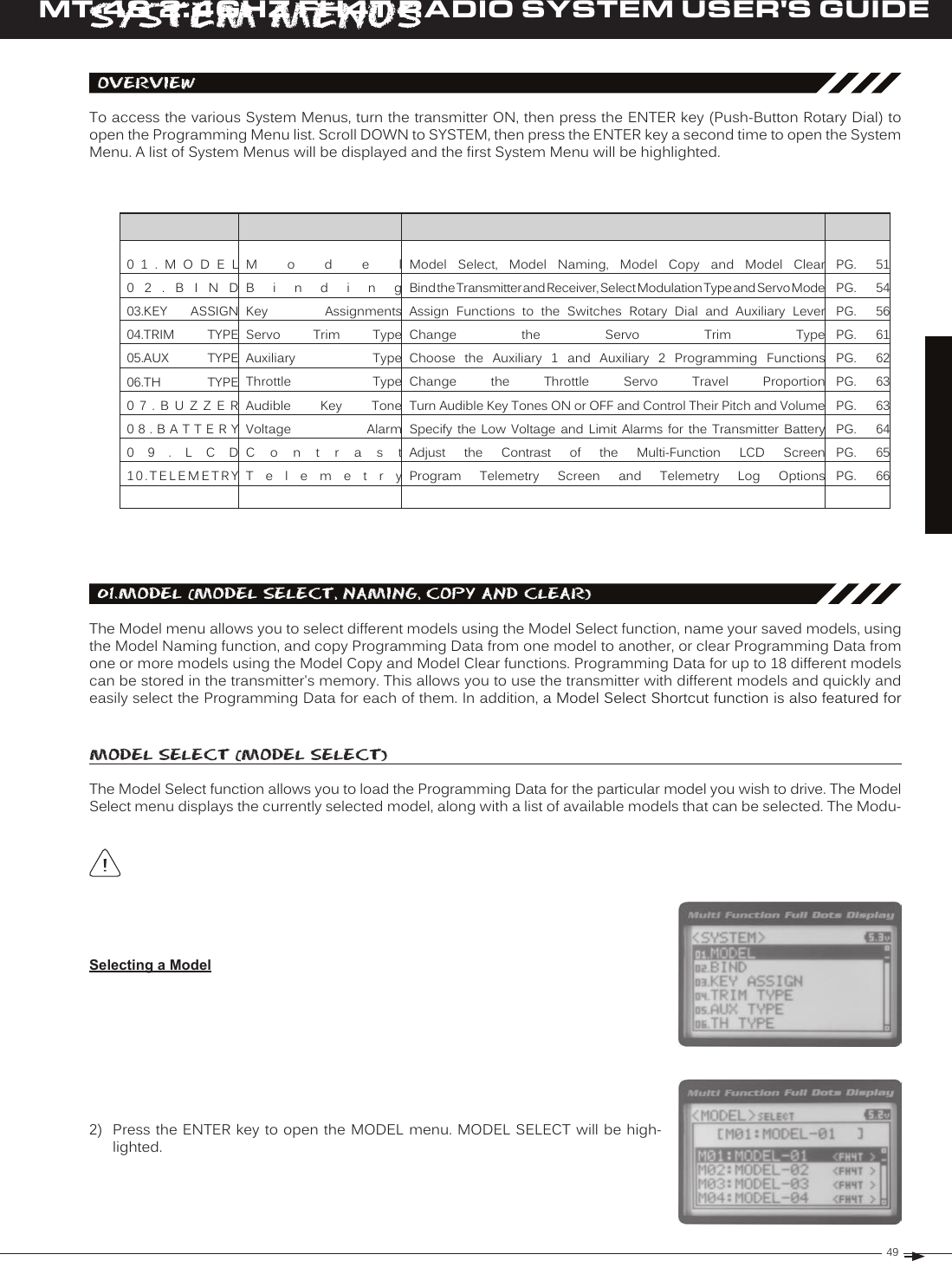
![50MT-4S 2.4GHZ FH4T RADIO SYSTEM USER'S GUIDET RWhen a model is selected, the Programming Data for that model will be load-Selecting a Model, Continued....4) Scroll UP or DOWN to highlight the model you would like to select, then press the ENTER key. Select this model? NO/YES will be displayed. Scroll DOWN to highlight YES, then press the ENTER key. The model that you just selected will be Model SeleCt (Model SeleCt), Continued....Model Select Shortcut (Direct Model)The Model Select Shortcut function allows you to jump directly to the DIRECT MODEL menu when you turn the transmit-1) Turn the transmitter OFF.2) Press and HOLD the Back/Cancel key, then turn the transmitter ON. The DIRECT MODEL menu will be displayed. To SySteM MenuSDeleting a Character1) Scroll UP or DOWN to move the underscore under the character in your Model Name you want to delete. Press the Model naMe (Model naMinG)The Model Naming function allows you to name each of the 18 individual models. This makes it easy to keep track of multiple models. The Model Name can consist of up to 10 letters, numbers, or symbols. Choose from capital letters, Entering a Model Name1) From within the MODEL menu, scroll DOWN to highlight MODEL NAME.2) Press the ENTER key. The MODEL NAME menu will be displayed, [BACK] will be highlighted and the underscore will be flashing under the first editable character A model must be selected before a Model Name can be entered or modified. In the default configuration, M01:MODEL-1 is selected. To enter a Model Name for another model, that model must first be selected using the 3) Scroll UP or DOWN to move the underscore to the character you would like change.4) Press the ENTER key, then scroll UP or DOWN to highlight a character in the Char-acter List. Press the ENTER key a second time to select the highlighted character. 5) Repeat steps 3 and 4 to enter the rest of the characters. Up to ten characters can be entered. Press the Back/Cancel To select lower case letters, numbers or symbols, continue to scroll UP or DOWN through the various Character If you can't move the underscore, press the Back/Cancel key to re-gain control of the underscore (the underscore](https://usermanual.wiki/Sanwa-Electronic-Instrument-Co/90490.User-Manual-Part-B/User-Guide-2232371-Page-38.png)
![51T RMT-4S 2.4GHZ FH4T RADIO SYSTEM USER'S GUIDESySteM MenuSDeleting a Model Name1) Scroll DOWN to move the underscore under the last character in your Model Name.2) Press the ENTER key. Scroll UP or DOWN to highlight [BACK], then continuously press the ENTER key to delete each Model naMe (Model naMinG), Continued....Model CoPy (Model ProGraMMinG data CoPy)The Model Copy function allows you to copy the Programming Data from one model to another model. For example, if you have two models that are similar, you can copy the Programming Data from the first model to the second model to 3) Scroll UP or DOWN to highlight the model you would like to copy the Program-Copying Model Programming Data1) From within the MODEL menu, scroll DOWN to highlight MODEL COPY.2) Press the ENTER key. The MODEL COPY menu will be displayed and the first The Model Copy function allows you to copy Programming Data FROM the currently selected model TO any other model in the Model Copy List. Make sure that prior to using the Model Copy function, you first select and load the 4) Press the ENTER key. Copy to this model? NO/YES will be displayed. Scroll DOWN to highlight YES, then press the ENTER key. After ~3 seconds, Executed All model-specific Programming Data, including the Model Name will be copied to the highlighted model. If you Model Clear (Model ProGraMMinG data reSet)The Model Clear function allows you to Reset model-specific Programming Data for any model back to the factory Clearing Model Programming DataWARNING: When the Model Clear function is Executed, all custom Programming Data for that model will be lost!If you can't move the underscore, press the Back/Cancel key to re-gain control of the underscore (the underscore](https://usermanual.wiki/Sanwa-Electronic-Instrument-Co/90490.User-Manual-Part-B/User-Guide-2232371-Page-39.png)
![52MT-4S 2.4GHZ FH4T RADIO SYSTEM USER'S GUIDET RSySteM MenuS4) Scroll DOWN to highlight YES, then press the ENTER key. After ~3 seconds, Executed will flash, indicating the Program-All model-specific Programming Data, including the Model Name and Modulation Type will be Reset to the default values. In addition, if you want to go back and change models or you don't want to Reset the Programming Data Model Clear (Model ProGraMMinG data reSet), Continued....2) From within the MODEL menu, scroll DOWN to highlight MODEL CLEAR.02.bindinG (bindinG, Modulation tyPe and Servo Mode)The Binding function allows you to 'Bind' the transmitter and receiver pair. When new, it is necessary to pair the transmit-ter and receiver to prevent interference from transmitters operated by other users. This operation is referred to as 'Bind-ing'. Once the Binding process is complete, the setting is remembered even when the transmitter and receiver are turned Changing the Modulation TypeThe Modulation Type function allows you to choose the transmitter Modulation Type. The Modulation Type can be changed to match the receiver you're using. For example, if you wish to use an Airtronics 2.4GHz FHSS-2 receiver with your transmitter, you would need to change the Modulation Type to FH2 prior to Binding your transmitter and receiver. The following Modulation Type options are available: FH2 - Select this Modulation Type when using Airtronics 2.4GHz FHSS-2 surface receivers. FH3 - Select this Modulation Type when using Airtronics 2.4GHz FHSS-3 receivers. FH3F - This Modulation Type is NOT used in North America. This Modulation Type is typically used in France. FH4T - Select this Modulation Type when using Airtronics 2.4GHz FHSS-4T Telemetry receivers.2) Press the ENTER key. The BIND menu will be displayed and [RF MODE] : FH4T will be highlighted. 3) Press the ENTER key, then scroll UP or DOWN to select the desired Modulation Type.The Modulation Type must be chosen prior to Binding the transmitter and receiver. Make sure the Modulation Type](https://usermanual.wiki/Sanwa-Electronic-Instrument-Co/90490.User-Manual-Part-B/User-Guide-2232371-Page-40.png)
![53T RMT-4S 2.4GHZ FH4T RADIO SYSTEM USER'S GUIDESySteM MenuS02.bindinG (bindinG, Modulation tyPe and Servo Mode), Continued....Changing the Channel Mode - FH2 Modulation Type Only1) From within the BIND menu, scroll DOWN to highlight [CH] : 4ch.2) Press the ENTER key, then scroll UP or DOWN to choose the desired Channel Mode. Selecting 2CH will enable 2-channel operation (Steering and Throttle). Se-BIND CH setting range is 2CH and 4CH. The default setting is 4CH. Changing the Servo Mode SettingThe Servo Mode setting can be changed to suit the type of servos you're using in your model. For example, using the SHR setting with Digital servos will increase the servo's response time, even above the manufacturer's stated specification. If you're using Airtronics SRG Digital servos, you can use the SSR setting for the fastest response time. The combination of using Digital servos and using the correct Servo Mode setting results in the ultimate feel and response, making you feel SHR and SSR Servo Modes should only be used with Digital servos. While the SHR Servo Mode can be used with WARNING: If you're using Analog servos in your model, DO NOT use SHR or SSR Servo Mode options for that channel. Use the NOR (Normal) Servo Mode with Analog servos. Using SHR or SSR Servo Mode options with Analog servos can result in poor performance or even damage to the servos or the receiver! In addition, not all ESCs are compatible with SHR or SSR Servo Modes. If your ESC does not operate correctly, change the Throttle Channel Servo Mode setting to 1) From within the BIND menu, scroll UP or DOWN to highlight the desired channel you would like to change the Servo Mode option for. Choose from either [ST] : 2) Press the ENTER key, then scroll UP or DOWN to choose the desired Servo SERVO MODE setting range is NOR, SHR and SSR. The default setting is NOR.Binding the Transmitter and ReceiverWe recommend that you choose your desired Servo Mode options prior to Binding the transmitter and receiver. Servo Mode option changes will not take effect immediately. If you change the Servo Mode after Binding the trans-](https://usermanual.wiki/Sanwa-Electronic-Instrument-Co/90490.User-Manual-Part-B/User-Guide-2232371-Page-41.png)
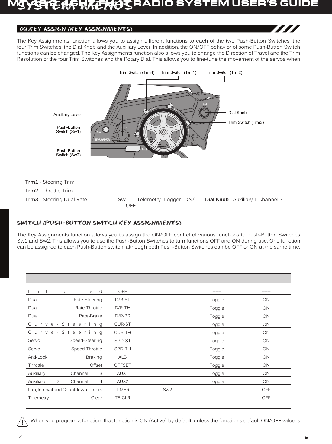
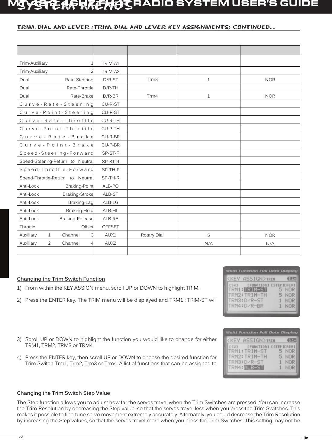
![55T RMT-4S 2.4GHZ FH4T RADIO SYSTEM USER'S GUIDESySteM MenuSChanging the Push-Button Switch Function1) From within the SYSTEM menu, scroll UP or DOWN to highlight the KEY ASSIGN 2) Press the ENTER key to open the KEY ASSIGN menu. SWITCH will be highlighted. 3) Press the ENTER key. The SWITCH menu will be displayed and SW1 : LOGGER 4) Scroll UP or DOWN to highlight the function you would like to change for either SW1 or SW2.5) Press the ENTER key, then scroll UP or DOWN to choose the desired function for either SW1 or SW2. A list of functions that can be assigned to the Push-Button SwitCH (PuSH-button SwitCH key aSSiGnMentS), Continued....Changing the Switch ModeSome functions allow you to change how the Push-Button Switch operates. The following Switch Modes are available: TOGGLE - When selected, press the Push-Button Switch to turn the function ON and press the Push-Button Switch a second time to turn the function OFF. See note at the bottom of the previous page. PUSH - When selected, press and HOLD the Push-Button Switch to turn the function ON. When the Push-Button 1) From within the KEY ASSIGN SWITCH menu, scroll DOWN to highlight the MODE you would like to change for either SW1 or SW2. 2) Press the ENTER key, then scroll UP or DOWN to choose the desired Switch The Switch Mode cannot be changed for all functions. When [MODE] ------, triM, dial and lever (triM, dial and lever key aSSiGnMentS)The Key Assignments function allows you to assign different functions to Trim Switches Trm1, Trm2, Trm3 and Trm4, the Rotary Dial and the Auxiliary Lever. This allows you to use the Trim Switches, Rotary Dial and Auxiliary Lever to control those functions while you're driving. In addition, the Direction of Travel (REV) and the Trim Resolution (Step value) of OFFTRIM-STInhibitedT r i m - S t e e r i n g Trm1------5------NOR](https://usermanual.wiki/Sanwa-Electronic-Instrument-Co/90490.User-Manual-Part-B/User-Guide-2232371-Page-43.png)
![60MT-4S 2.4GHZ FH4T RADIO SYSTEM USER'S GUIDET R05.auX tyPe (auXiliary tyPe)The Auxiliary Type function allows you choose which Auxiliary function is assigned to Auxiliary 1 Channel 3 or Auxiliary 2 Channel 4. One Auxiliary function can be assigned to each Auxiliary Channel and both Auxiliary Channels can be Active and controlled at the same time using different controls. For example, you can control Auxiliary 1 Channel 3 using the This section details how to assign the different Auxiliary functions to the Auxiliary Channels. For details about pro-gramming and using each of the Auxiliary functions, see the Auxiliary 1 Programming section on pages 29 ~ 35 or Changing the Auxiliary Function2) Press the ENTER key. The AUX TYPE menu will be displayed and AUX1 : STEP AUX will be highlighted.3) Scroll UP or DOWN to highlight the desired channel you would like to change 4) Press the ENTER key, then scroll UP or DOWN to choose the desired Auxiliary AUX TYPE setting range is STEP AUX, POINT AUX, 4WS MIX, MOA MIX and AUX MIX. The default setting for both channels is STEP AUX.Some Auxiliary functions allow you to change the Mode. Details of the various Mode options and how to change them from within the Auxiliary Type function menu can be found in the specific Auxiliary function pro-SySteM MenuSChanging the Trim Type, Continued....2) Press the ENTER key. The TRIM TYPE menu will be displayed and [ST] CENT will be highlighted.3) Scroll UP or DOWN to highlight the desired channel you would like to change the Trim Type option for. Choose from either [ST] CENT (Steering), [TH] CENT 4) Press the ENTER key, then scroll UP or DOWN to choose the desired Trim Type TRIM TYPE setting range is CENT and PARA. The default setting for all channels is](https://usermanual.wiki/Sanwa-Electronic-Instrument-Co/90490.User-Manual-Part-B/User-Guide-2232371-Page-48.png)
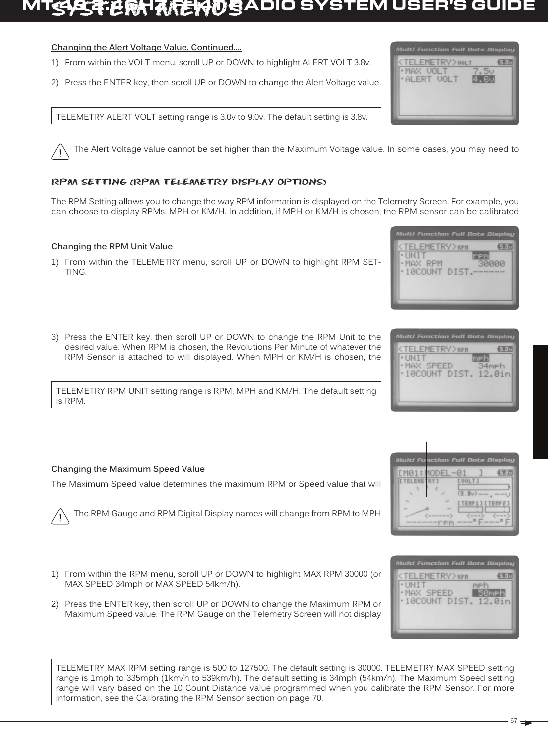
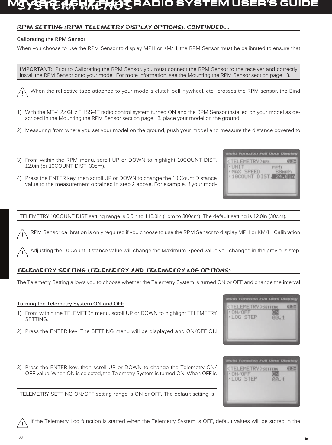
![65T RMT-4S 2.4GHZ FH4T RADIO SYSTEM USER'S GUIDESySteM MenuS1) From within the TEMP1 or TEMP2 menu, scroll UP or DOWN to highlight MAX TEMP 248ºF (or 120ºC).2) Press the ENTER key, then scroll UP or DOWN to change the Maximum Tem-perature value. The Temperature Display Monitor on the Telemetry Screen will Changing the Maximum Temperature ValueThe Maximum Temperature value determines the maximum temperature shown on the [TEMP1] or [TEMP2] Telemetry Screen Temperature Display Monitors. This allows you to calibrate each Temperature Display Monitor to match what the Tempera-TELEMETRY MAX TEMP setting range is 68ºF to 302ºF (0ºC to 150ºC). The default setting is 248ºF (120ºC).The Maximum Temperature value cannot be set lower than the Alert Temperature value or the Minimum Tempera-1) From within the TEMP1 or TEMP2 menu, scroll UP or DOWN to highlight ALERT TEMP 212ºF (or 100ºC).2) Press the ENTER key, then scroll UP or DOWN to change the Alert Temperature value. The Alert Temperature value is the temperature that the Temperature Changing the Alert Temperature ValueThe Alert Temperature value determines the temperature at which the Temperature Alert alarm will sound. For example, you can set an Alert Temperature value for your Nitro engine that will alert you when your engine's cylinder head tem-perature is getting too hot. When the Alert Temperature value is reached, the Temperature Alert alarm will sound and LED2 (Red) will flash. The Temperature Alert alarm will sound for approximately 5 seconds, however, LED2 will con-tinue to flash until the temperature drops below the Alert Temperature value. The audible portion of the Temperature TELEMETRY ALERT TEMP setting range is 68ºF to 302ºF (0ºC to 150ºC). The default setting is 212ºF (100ºC).The Alert Temperature value cannot be set higher than the Maximum Temperature value. In addition, the Alert Temperature value cannot be set lower than the Minimum Temperature value. In some cases, you may need to Changing the Minimum Temperature ValueThe Minimum Temperature value determines the Minimum temperature shown on the [TEMP1] or [TEMP2] Telemetry Screen Temperature Display Monitors. This al-lows you to calibrate each Temperature Display Monitor to match what the Tem-teMP1 and teMP2 SettinG (teMPerature teleMetry diSPlay oPtionS), Continued....](https://usermanual.wiki/Sanwa-Electronic-Instrument-Co/90490.User-Manual-Part-B/User-Guide-2232371-Page-53.png)
![66MT-4S 2.4GHZ FH4T RADIO SYSTEM USER'S GUIDET RSySteM MenuSChanging the Minimum Temperature Value, Continued....1) From within the TEMP1 or TEMP2 menu, scroll UP or DOWN to highlight MIN TEMP 68ºF (or 20ºC).2) Press the ENTER key, then scroll UP or DOWN to change the Minimum Tem-perature value. The Temperature Display Monitor on the Telemetry screen will TELEMETRY MIN TEMP setting range is 32ºF to 302ºF (0ºC to 150ºC). The default setting is 68ºF (20ºC).The Minimum Temperature value cannot be set higher than the Alert Temperature value or the Maximum volt SettinG (reCeiver battery voltaGe teleMetry diSPlay oPtionS)The Voltage Setting you to change the way receiver battery Voltage information is displayed on the Telemetry Screen 1) From within the TELEMETRY menu, scroll UP or DOWN to highlight VOLT SET-TING.Changing the Maximum Voltage ValueThe Maximum Voltage value determines the maximum receiver battery Voltage that will be shown on the [VOLT] Telemetry Screen Display Monitor. This allows you to calibrate the Voltage Display Monitor to match your model's receiver battery. This The Maximum Voltage value cannot be set lower than the Alert Voltage value. If necessary, you may need to lower TELEMETRY MAX VOLT setting range is 3.0v to 9.0v. The default setting is 9.0v.3) Press the ENTER key, then scroll UP or DOWN to change the Maximum Voltage value. The Voltage Display Monitor on the Telemetry Screen will not display re-Changing the Alert Voltage ValueThe Alert Voltage value determines the voltage at which the Voltage Alert alarm will sound. For example, you can set the Alert Voltage value to alert you to when your model's receiver battery is getting low and needs to be recharged. When the Alert Voltage value is reached, the Voltage Alert alarm will sound and LED2 (Red) will flash. The Voltage Alert alarm will sound for approximately 5 seconds, however, LED2 will continue to flash until you recharge the receiver battery. The Refer to the manufacturer of your model's receiver battery to determine the safest Alert Voltage value to use. In general, the Alert Voltage value should be high enough to alert you when it's time to recharge your receiver battery,](https://usermanual.wiki/Sanwa-Electronic-Instrument-Co/90490.User-Manual-Part-B/User-Guide-2232371-Page-54.png)