Sanwa Electronic Instrument Co 90490 2.4GHz RADIO CONTROL SYSTEM User Manual Part B
Sanwa Electronic Instrument Co Ltd 2.4GHz RADIO CONTROL SYSTEM Part B
Contents
- 1. User Manual Part B
- 2. User Manual Part A
User Manual Part B
13
T R
MT-4S 2.4GHZ FH4T RADIO SYSTEM USER'S GUIDE
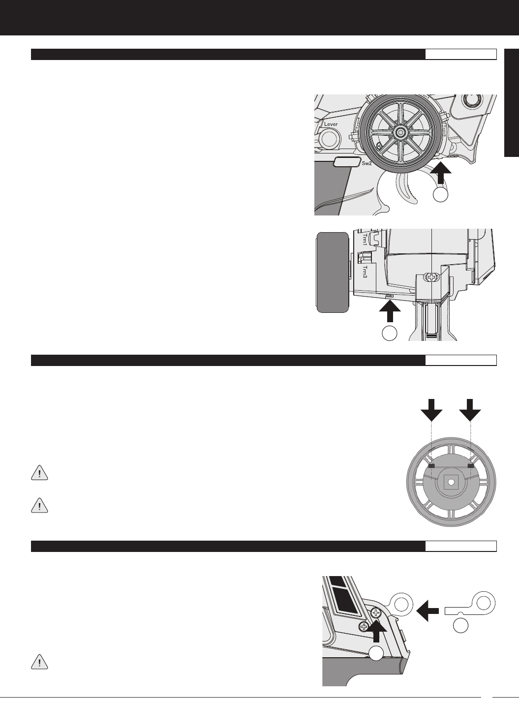
The maximum right and left travel of the steering wheel can be adjusted to best suit the feel of the steering wheel and your driving
style. Some drivers prefer to limit the travel of the steering wheel as it makes them feel more 'connected' to their model.
To adjust the maximum travel of the steering wheel, follow the steps below:
1) Remove the foam steering wheel grip from the steering wheel by firmly pulling it straight off.
2) To limit the maximum travel of the steering wheel, use a 1.5mm hex wrench to turn both grub
screws (A) clockwise equally the desired amount. To maximize the travel of the steering wheel,
turn both grub screws counter-clockwise equally the desired amount.
After making steering wheel travel adjustments, you must use the Variable Rate Adjustment
function to ensure your steering servo travel limits are equal. For more information, see the
Variable Rate Adjustment section on page XX.
Limiting the maximum travel of the steering wheel will increase the sensitivity of the steering.
We recommend setting negative Exponential to soften the control feel around Neutral. For
more information, see the Exponential and ARC Adjustment section on pages XX through XX.
To adjust the steering wheel spring tension, follow the step below:
1) To increase the spring tension of the steering wheel (firmer), use a
1.5mm hex wrench to turn the Steering Wheel Tension Adjustment
Screw (A) clockwise. To decrease the spring tension of the steering
wheel (looser), turn the Steering Wheel Tension Adjustment Screw
counter-clockwise.
A
The spring tension of the throttle trigger and steering wheel can be adjusted to best suit the user. Some users may prefer the
throttle trigger and/or steering wheel to feel 'firmer' and some users may prefer them to feel 'softer'. It all depends on your
personal preference.
A
To adjust the throttle trigger spring tension, follow the step below:
1) To increase the spring tension of the throttle trigger (firmer), use a
1.5mm hex wrench to turn the Throttle Trigger Tension Adjustment
Screw (A) clockwise. To decrease the spring tension of the throttle
trigger (looser), turn the Throttle Trigger Tension Adjustment Screw
counter-clockwise.
A wrist strap anchor is included that can be installed onto the transmitter to facilitate the use of a wrist strap (not included).
A
B
To install the wrist strap anchor, follow the steps below:
1) Remove the self-tapping screw (A) from the transmitter, using a # 1 philips
head screwdriver.
2) Slide the wrist strap anchor into the mounting slot in the back of the
transmitter, then reinstall and tighten the self-tapping screw.
When installing the wrist strap anchor, note its orientation. The U-Shaped
groove in the base of the wrist strap anchor should be pointing down.
THROTTlE TRIGGER AnD STEERInG wHEEl SpRInG TEnSIOn ADjUSTMEnT GEnERAl
STEERInG wHEEl TRAvEl ADjUSTMEnT GEnERAl
wRIST STRAp AncHOR GEnERAl
GENERAL
14
MT-4S 2.4GHZ FH4T RADIO SYSTEM USER'S GUIDE
T R
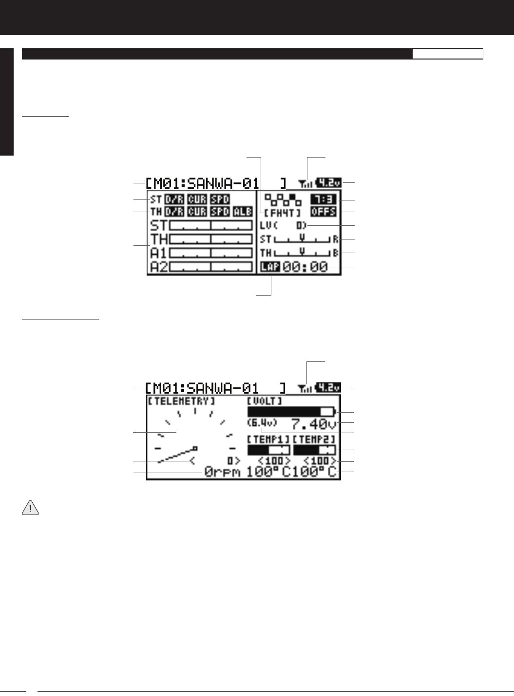
Model Number and Name
Timer Display
Digital Voltage Indicator
Steering Trim Display
Throttle Trim Display
Servo Monitor Display
Telemetry Signal Indicator
Throttle Mode Indicator
Throttle Offset Indicator
Auxiliary Lever Position Display
Timer Type Indicator
Steering Program Indicator
Throttle Program Indicator
Modulation Type Indicator
TOP Screen:
The TOP screen is displayed when you turn the transmitter ON. The TOP screen displays all pertinent information, such as the
Model Name, Modulation Type, Timer, Servo Monitor and much more.
TELEMETRY Screen:
The TELEMETRY screen displays all pertinent telemetry information, such as RPM, Temperature and Receiver Voltage. To display
the TELEMETRY screen, from the TOP screen scroll DOWN using the Push-Button Rotary Dial.
Auxiliary Lever Position Display: Displays the current position of the Auxiliary Lever.
Digital RPM Display: Displays the current RPM from the RPM Sensor in digital format.
Digital Temperature Display: Displays the current temperature from the TEMP1 and TEMP2 Temperature Sensors in digital
format.
Digital Voltage Indicator: Indicates the current Voltage of the transmitter batteries.
High RPM Display: Displays the last highest RPM value. This value can be Reset. For more information, see the Telemetry Clear
Function section on page XX.
High Temperature Display: Displays the last highest Temperature value. These values can be Reset. For more information, see
the Telemetry Clear Function section on page XX.
Modulation Type Indicator: Indicates the current Modulation Type that the transmitter is set to.
Model Number and Name: Displays the Model Number and Model Name of the currently selected model.
Model Number and Name Digital Voltage Indicator
Receiver Voltage Display
Digital Temperature Display
RPM Display Monitor
Digital RPM Display
High RPM Display
Telemetry Signal Indicator
High Temperature Display
Voltage Alert Indicator
Temperature Display Monitor
Voltage Display Monitor
TOp ScREEn AnD TElEMETRY ScREEn OvERvIEw GEnERAl
Use the information in this section to familiarize yourself with the layout and different indicators and displays that comprise the
TOP screen and TELEMETRY screen.
The TOP screen will always be displayed when you turn the transmitter ON, regardless of which screen was last displayed.
Full telemetry support requires the use of an Airtronics 2.4GHz FH4T telemetry-capable surface receiver, such as the
RX-461 or RX-462 (available separately). The included RX-472 receiver can send telemetry data for the voltage of
the receiver battery pack only, unless used with the Airtronics Super Vortex ZERO ESC (available separately), plugged into the
BATT/SSL slot of the included RX-472 receiver.
15
T R
MT-4S 2.4GHZ FH4T RADIO SYSTEM USER'S GUIDE
The MT-4S transmitter features a Push-Button Rotary Dial and a BACK/CANCEL key that are used to facilitate transmitter
programming. This section summarizes the functions of the Push-Button Rotary Dial and the BACK/CANCEL key.
Receiver Voltage Display: Displays the current voltage of the receiver battery.
RPM Display Monitor: Displays the current RPM from the RPM Sensor in graphical format.
Servo Monitor Display: Displays the output levels of the four different channels in bar graph form, allowing you to monitor servo
operation in a virtual manner.
Steering Program Indicator: Indicates up to four different programming options that are currently programmed to the Steering
channel. The Steering Program Indicator will only be displayed if a Steering channel Programming Value is programmed.
Steering Trim Display: Displays the current position of the Steering Trim Switch.
Telemetry Signal Indicator: Indicates the current signal strength of the Telemetry connection between the transmitter and
receiver. The Telemetry Signal Indicator will only be displayed when the receiver is turned ON and there is a Telemetry con-
nection Active.
Temperature Display Monitor: Displays the current TEMP1 and TEMP2 temperatures in bar graph format.
Throttle Mode Indicator: Indicates the current Throttle Mode type.
Throttle Offset Indicator: Indicates that the Throttle Offset function is programmed. The Throttle Offset Indicator will only be
displayed if a Throttle Offset percentage value is programmed.
Throttle Program Indicator: Indicates up to four different programming options that are currently programmed to the Throttle
channel. The Throttle Program Indicator will only be displayed if a Throttle channel Programming Value is programmed.
Throttle Trim Display: Displays the current position of the Throttle Trim Switch.
Timer Display: Displays the time of the currently selected Timer.
Timer Type Indicator: Indicates the current Timer Type selected, either LAP or INT (Interval).
Voltage Alert Indicator: Indicates the currently programmed Voltage value that the receiver Voltage Alert alarm will sound at.
Voltage Display Monitor: Displays the current receiver battery voltage in bar graph format.
PRO TIP: While navigating Programming Menus and changing Programming Values, keep the following in mind: to choose
an option to program, scroll UP or DOWN to highlight the desired option. Press the ENTER key and the highlighted option will
flash, indicating the Programming Value can be changed. Once you've changed the Programming Value, press the ENTER
key again or press the BACK/CANCEL key and the highlighted option will stop flashing, indicating you can scroll UP or DOWN
to highlight another programming option.
Scrolls between TOP and TELEMETRY screens. Scrolls the
Programming Cursor RIGHT or UP and LEFT or DOWN. Increases
or Decreases Programming Values.
PROGRAMMING KEY NAME FUNCTION
Push-Button Rotary Dial
(Push ENTER)
Opens the selected menu or programming option. Press and
HOLD to reset the Selected programming option to its default
value.
BACK/CANCEL Key Returns to the previous menu. Press and HOLD to return to the
TOP screen.
Push-Button
Rotary Dial
(Scroll UP/DOWN)
pROGRAMMInG kEYS OvERvIEw AnD FUncTIOnS GEnERAl
GENERAL
TOp ScREEn AnD TElEMETRY ScREEn OvERvIEw, cOnTInUED.... GEnERAl
16
MT-4S 2.4GHZ FH4T RADIO SYSTEM USER'S GUIDE
T R
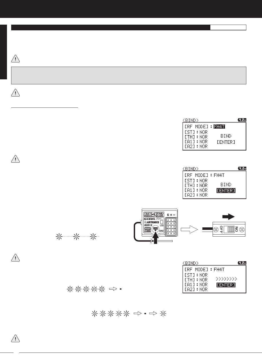
The Binding function allows you to 'Bind' the transmitter and receiver pair. When new, it is necessary to pair the transmitter and
receiver to prevent interference from transmitters operated by other users. This operation is referred to as 'Binding'. Once the
Binding process is complete, the setting is remembered even when the transmitter and receiver are turned OFF. Therefore, this
procedure usually only needs to be done once.
Under some circumstances, the receiver may not operate after turning the transmitter and receiver ON. If this occurs,
perform the Binding process again.
Before beginning the Binding process, connect your servos and receiver battery pack to the receiver. For more information,
see the
Receiver Connections and Mounting
section on page XX. The transmitter and the receiver should be turned OFF.
4) While holding down the Bind Button on the receiver,
turn the receiver ON. The Bind LED on the receiver will
flash slowly. After approximately 2 seconds, release the
Bind Button. The Bind LED on the receiver will continue to
flash slowly.
Transmitter and Receiver Binding:
1) Turn the transmitter ON. The TOP screen will be displayed. Press the ENTER key (Push-Button Rotary Dial) to open the
Programming Menu list, then scroll UP or DOWN to highlight the SYSTEM menu.
5) Press the ENTER key. The [ENTER] command will begin to flash and the Bind LED on
the receiver will flash rapidly, then go out.
6) After the Bind LED on the receiver goes out, press the ENTER key a second time. The Bind LED on the receiver will illuminate
solid blue and LED 2 on the transmitter will go out, indicating that the Binding procedure is complete and a Telemetry
connection has been made.
Verify that the Modulation is set to [RF MODE]: FH4T is displayed an that the Servo Operating Mode for each channel is set
to NOR. If it isn't, change the Modulation Type to FH4T. If you need to change any of these settings, see the
BIND Menu
section on pages XX through XX.
3) Scroll UP or DOWN to highlight the [ENTER] command. Do not press the ENTER key yet.
7) Move the steering wheel and throttle trigger to verify that the servos are operating normally, then press and HOLD the
Back/Cancel key to return to the TOP screen.
When the Binding procedure is successful, the Bind LED on the receiver and LED 1 on the transmitter will illuminate solid
blue. If the Bind LED on the receiver is flashing rapidly or is not illuminated at all, the transmitter and receiver are not
paired. In this case, turn both the transmitter and receiver OFF, then repeat the Binding procedure again.
bInDInG THE TRAnSMITTER AnD REcEIvER GEnERAl
IMPORTANT: This section details Binding the RX-472 4-Channel 2.4GHz FH4T Super Response receiver with the Servo
Operating Mode set to Normal mode. If you are Binding an FH2 or FH3 receiver, or if you prefer to change the Servo Operating
Mode, see the
BIND Menu
section on pages XX through XX.
2) Press the ENTER key to open the SYSTEM menu, then scroll DOWN to highlight the
BIND menu. Press the ENTER key to open the BIND menu.
You must complete step 5 below within 10 seconds or the Bind LED will go out, indicating the receiver has timed out. If
this occurs, turn the receiver OFF, then repeat step 4.
17
T R
MT-4S 2.4GHZ FH4T RADIO SYSTEM USER'S GUIDE
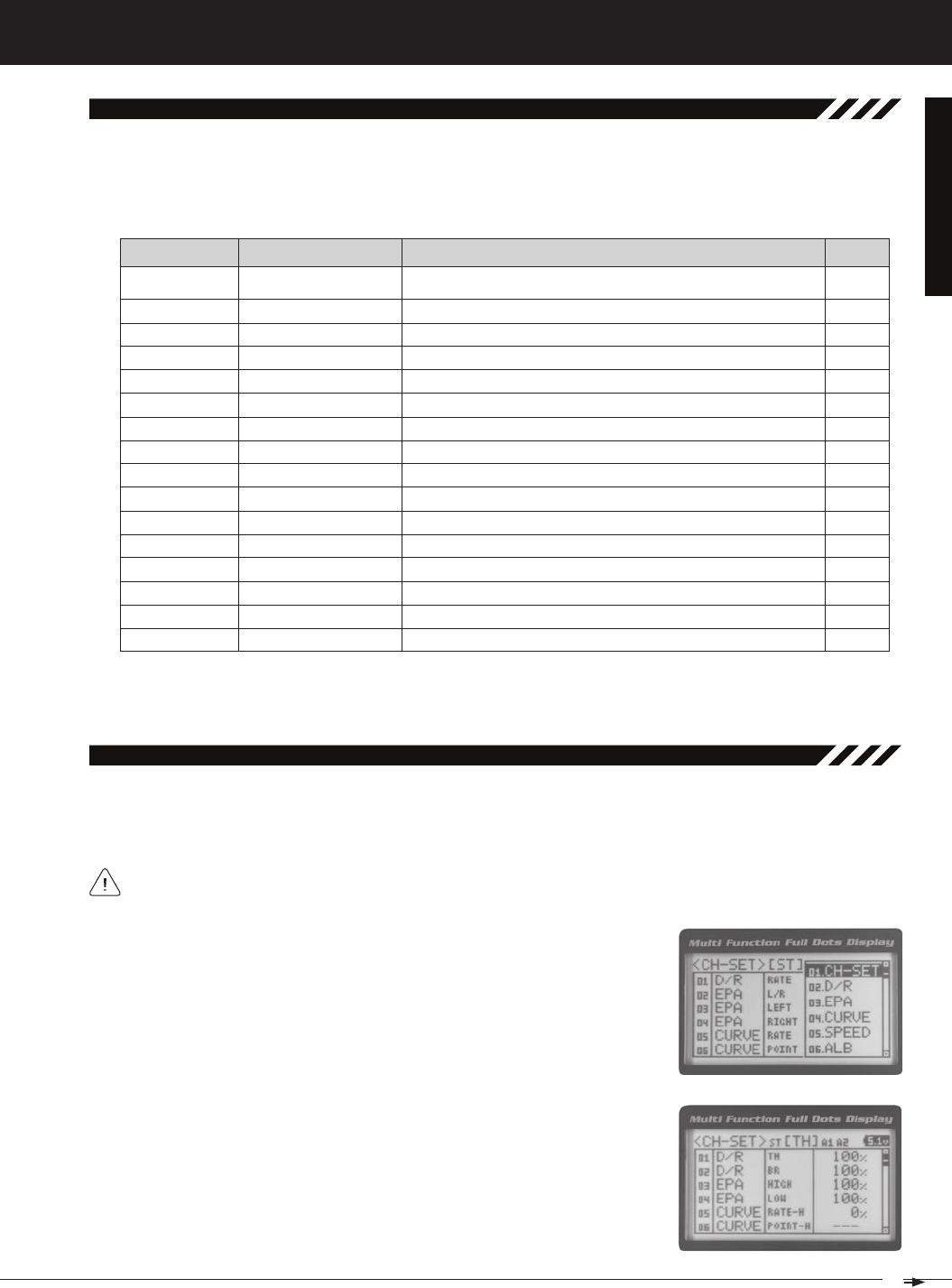
01.CH-Set (CHannel Set)
The Channel Set function allows you to make programming changes to each of the four channels without the need to
enter each Programming Menu separately. Essentially, the Channel Set function encompasses the most common pro-
gramming options in one convenient location. For example, you can make all of your desired programming changes,
such as End Point Adjustment, Exponential, Servo Speed, Fail Safe settings, etc., for each channel, all from within the
same menu.
To access the various Programming Menus, turn the transmitter ON, then press the ENTER key (Push-Button Rotary Dial).
A list of Programming Menus will be displayed along the right side of the screen and the last Programming Menu when
the transmitter was turned OFF will be highlighted. The currently highlighted Programming Menu will be displayed in the
background.
The following Programming Menus are available by scrolling UP or DOWN using the Push-Button Rotary Dial:
overview
01.CH-SET
02.D/R
03.EPA
04.CURVE
05.SPEED
06.ALB
07.OFFSET
08.AUX1
09.AUX2
10.TRIM
11.REV
12.TIMER
13.LAP
14.F/S
15.LOGGER
16.SYSTEM
Channel Set
Dual Rate
End Point Adjustment
Curve
Servo Speed
Anti-Lock Braking
Throttle Offset
Auxiliary 1
Auxiliary 2
Servo Trim
Servo Reversing
Lap and Interval Timers
Lap Times
Fail Safe
Telemetry Logging
System Menu
Change Common Programming Options in One Convenient Location
Adjust Channel Dual Rates
Adjust Channel End Points
Adjust Channel Exponential or Adjustable Rate Control (ARC)
Slow Down Servo Speed in the Forward and Return to Neutral Direc-
tions
Program the Anti-Lock Braking Function
Program the Throttle Offset Position
Choose and Adjust Auxiliary 1 Channel 3 Functions and Programming
Choose and Adjust Auxiliary 2 Channel 4 Functions and Programming
Adjust Servo Trim and Servo Sub-Trim
Change the Direction that the Servos Travel
Program the Lap Timer and the Interval Timer
Displays Current, Past and Best Lap Times
Program Fail Safe Settings
View Logs of Temperature, Voltage and RPM Telemetry Data
Access the System Menu
M E N U MENU NAME MENU DESCRIPTION
PROGRAMMING
MENUS
1) From the TOP screen, press the ENTER key to open the Programming Menu list.
2) Scroll UP or DOWN to highlight the CH-SET menu, then press the ENTER key. The
CH-SET menu will be displayed and the cursor will default to [ST].
This section details how to use the Channel Set function. For information about programming each of the Program-
ming Menus within the CH-SET menu, refer to the specific Programming Menu sections on the pages shown in
the table above.
PAGE #
PG. 19
PG. 20
PG. 22
PG. 23
PG. 25
PG. 27
PG. 28
PG. 29
PG. 36
PG. 42
PG. 44
PG. 44
PG. 47
PG. 48
PG. 49
PG. 51
3) Scroll DOWN to move the cursor to the channel you would like to make Program-
ming Value changes to. Choose from <CH-SET> [ST] (Steering), <CH-SET> [TH]
(Throttle), <CH-SET> [A1] (Auxiliary 1) or <CH-SET> [A2] (Auxiliary 2).
18
MT-4S 2.4GHZ FH4T RADIO SYSTEM USER'S GUIDE
T R
01.CH-Set (CHannel Set), Continued....
6) After changing the desired Programming Value, press the ENTER key or the Back/Cancel key and the highlighted
option will stop flashing, indicating you can scroll UP or DOWN to highlight another programming option. To change
to another channel, press the Back/Cancel key, then scroll UP or DOWN to select the desired channel. Repeat steps
4 and 5 above to change the desired Programming Values for that channel.
4) Press the ENTER key to highlight the Programming Value in the upper right cor-
ner.
5) Scroll UP or DOWN to highlight the Programming Value you would like to change,
then press the ENTER key to select it. The highlighted Programming Value will
01.D/R - RATE
02.EPA - L/R
03.EPA - LEFT
04.EPA - RIGHT
05.CURVE - RATE
06.CURVE - POINT
07.SPEED - FORWARD
08.SPEED - RETURN
09.TRIM
10.SUB-T
11.REV - NOR/REV
12.F/S
01.D/R - TH
02.D/R - BR
03.EPA - HIGH
04.EPA - LOW
05.CURVE - RATE-H
06.CURVE - POINT-H
07.CURVE - RATE-B
08.CURVE - RATE-H
09.SPEED - FORWARD
10.SPEED - RETURN
11.ALB - POINT
12.ALB - STROKE
13.ALB - LAG
14.ALB - RELEASE
15.ALB - HOLD
16.TRIM
17.SUB-T
18.REV - NOR/REV
01.EPA - HIGH
02.EPA - LOW
03.CURVE - RATE
04.CURVE - POINT
05.CURVE
06.CURVE
07.SPEED - FORWARD
08.SPEED - RETURN
09.TRIM
10.SUB-T
11.REV - NOR/REV
01.EPA - HIGH
02.EPA - LOW
03.CURVE - RATE
04.CURVE - POINT
05.CURVE
06.CURVE
07.SPEED - FORWARD
08.SPEED - RETURN
09.TRIM
10.SUB-T
11.REV - NOR/REV
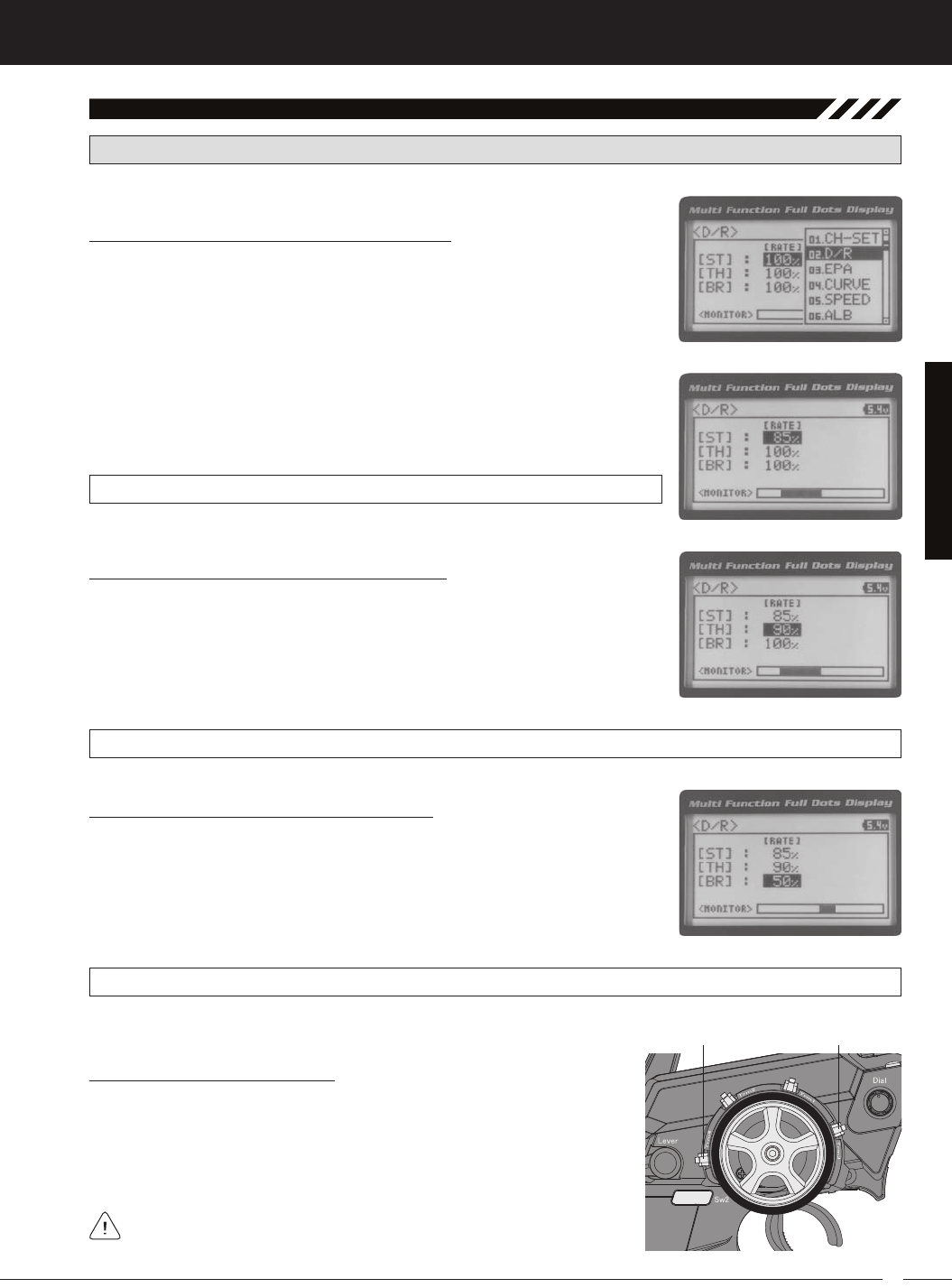
02.d/r (dual rate)
Dual Rate is a percentage of End Point Adjustment. For example, if you set the Steering Dual Rate percentage
value to 100%, the steering will travel the same amount as defined by your End Point Adjustment programming. If you
The Dual Rate function allows you to change the control authority of the Steering, Throttle High Side and Throttle Brake
Side by changing the amount of servo travel relative to control input. For example, by increasing the Steering Dual Rate,
you can make the steering servo travel more which might prevent your model from pushing during turns. If your model
[[ProGraMMinG MenuS
IMPORTANT: Prior to programming the Dual Rate function, you should adjust the maximum Left and Right (or High
and Low) End Points, using the End Point Adjustment function. For more information, see the End Point Adjustment
section on pages 22 and 23.
19
T R
MT-4S 2.4GHZ FH4T RADIO SYSTEM USER'S GUIDE
D/R ST RATE setting range is 0% to 100%. The default setting is 100%.
3) Press the ENTER key, then scroll UP or DOWN to increase or decrease the Steer-
ing Dual Rate percentage value. When the Steering Dual Rate percentage value is
decreased, steering servo travel is decreased. When the Steering Dual Rate per-
02.d/r (dual rate), Continued....
Adjusting the Steering Dual Rate Percentage Value
1) From the TOP screen, press the ENTER key to open the Programming Menu list.
2) Scroll UP or DOWN to highlight the D/R menu, then press the ENTER key. The D/R
[[ProGraMMinG MenuS
Adjusting the Throttle Dual Rate Percentage Value
1) From within the D/R menu, scroll UP or DOWN to highlight [TH] : RATE 100%.
2) Press the ENTER key, then scroll UP or DOWN to increase or decrease the Throttle
Dual Rate percentage value. When the Throttle Dual Rate percentage value is de-
creased, Throttle High side servo travel is decreased. When the Throttle Dual Rate
D/R TH RATE setting range is 0% to 100%. The default setting is 100%.
Adjusting the Brake Dual Rate Percentage Value
1) From within the D/R menu, scroll UP or DOWN to highlight [BR] : RATE 100%.
2) Press the ENTER key, then scroll UP or DOWN to increase or decrease the Brake
Dual Rate percentage value. When the Brake Dual Rate percentage value is de-
creased, Throttle Brake side servo travel is decreased. When the Brake Dual Rate
D/R BR RATE setting range is 0% to 100%. The default setting is 100%.
PRO TIP: Use the Servo Monitor at the bottom of the Dual Rate menu to see your programming changes in virtual real
Controlling the Dual Rate Function
1) By assigning the Steering, Throttle and Brake Dual Rate programming func-
tions to one or more of the Trim Switches, Auxiliary Lever or Dial Knob, these
functions can be adjusted while driving without accessing the Program-
ming Menu. In addition, these functions can be toggled OFF and ON by
assigning them to one or more Push-Button Switches. For more information,
In the default configuration, the Steering and Throttle Dual Rate program-
20
MT-4S 2.4GHZ FH4T RADIO SYSTEM USER'S GUIDE
T R
[[ProGraMMinG MenuS
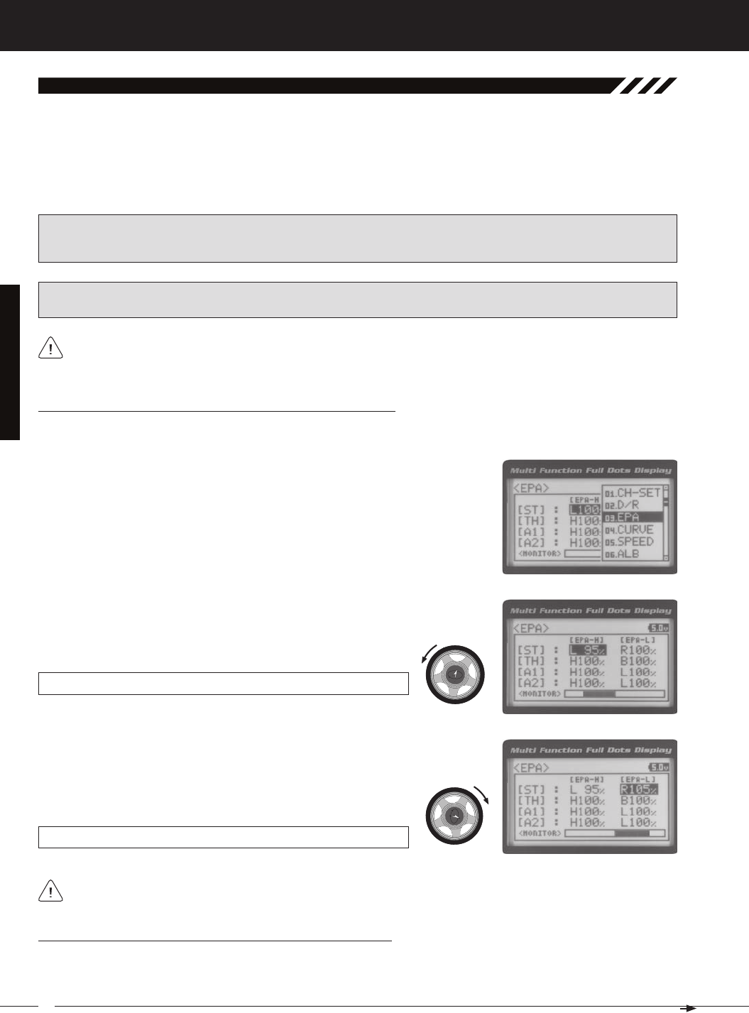
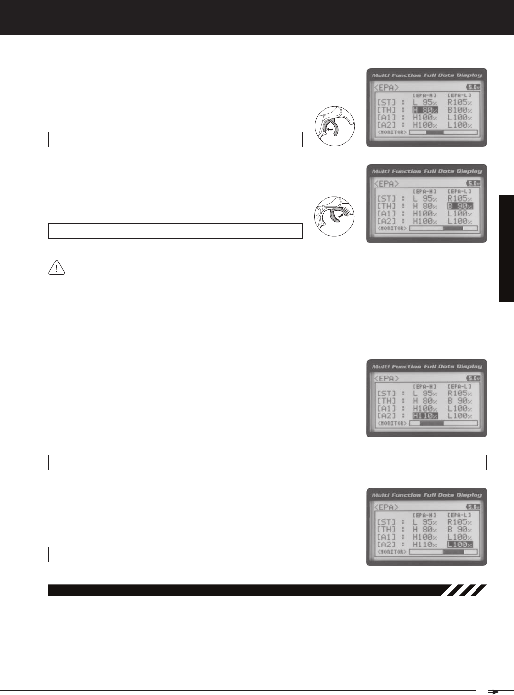
03.ePa (end Point adjuStMent)
The End Point Adjustment function allows you to adjust servo travel in each direction. This makes it possible to balance
servo travel in both directions and set the maximum desired amount of servo travel. For example, on a gas-powered
model, if you pull the throttle trigger and the carburetor does not open completely, you can increase the Throttle High End
Point Adjustment so that the carburetor opens completely. Another example is with steering. If your model turns sharper
to the right than to the left, you can increase the Steering Left End Point Adjustment to balance the steering. The End
Point Adjustment function can be adjusted for the Steering channel (Right and Left), the Throttle channel (Throttle High
PRO TIP: Use the Servo Monitor at the bottom of the End Point Adjustment menu to see your programming changes
in virtual real time.
WARNING End Point Adjustment percentage values should not be increased to the point where your linkages and
servos bind when moved all the way to the right or left. Binding will cause the servos to 'buzz', resulting in a quicker
loss of battery power and eventual damage to the servos.
1) From the TOP screen, press the ENTER key to open the Programming Menu list.
2) Scroll UP or DOWN to highlight the EPA menu, then press the ENTER key. The
Before making End Point Adjustments, the servo horn needs to be centered. Install the servo horn onto the servo,
making sure it's as close to being centered as possible, then use the Servo Sub-Trim function to center the servo
Adjusting the Steering End Point Adjustment Percentage Values
Your model’s turning radius can differ from left to right because of variations in linkage, suspension balance, tire diameter,
or weight distribution. In such cases, Left Steering servo travel and Right Steering servo travel are adjustable using the
EPA ST R setting range is 0% to 150%. The default setting is 100%.
4) From within the EPA menu, scroll DOWN to highlight [ST] : EPA R100%. Press
the ENTER key, then scroll UP or DOWN to increase or decrease the Steering
Right End Point Adjustment percentage value. Increasing the percentage value
will increase steering servo travel in that direction and decreasing
3) Press the ENTER key, then scroll UP or DOWN to increase or decrease the Steering
Left End Point Adjustment percentage value. Increasing the percentage value will
increase steering servo travel in that direction and decreasing the percentage value
EPA ST L setting range is 0% to 150%. The default setting is 100%.
Adjusting the Throttle End Point Adjustment Percentage Values
Your model's carburetor may not open completely, or it may open too much and cause the throttle servo to bind. If you're
using an Electronic Speed Control, the Electronic Speed Control may not command full power, or the brake may not
Steering EPA L/R can be adjusted from within the Channel Set menu. This option changes both Left and Right
21
T R
MT-4S 2.4GHZ FH4T RADIO SYSTEM USER'S GUIDE
[[ProGraMMinG MenuS
If you're using an Electronic Speed Control, the Throttle High and the Throttle Brake End Point Adjustment per-
centage values are both generally set to 100%, although the Throttle High direction may need to be increased to
1) From within the EPA menu, scroll UP or DOWN to highlight [TH] : EPA H 100%.
2) Press the ENTER key, then scroll UP or DOWN to increase or decrease the Throttle
High End Point Adjustment percentage value. Increasing the percentage value will
increase Throttle High servo travel in that direction and decreasing
EPA TH H setting range is 0% to 150%. The default setting is 100%.
EPA TH B setting range is 0% to 150%. The default setting is 100%.
3) From within the EPA menu, scroll DOWN to [TH] : EPA B100%. Press the EN-
TER key, then scroll UP or DOWN to increase or decrease the Throttle Brake
End Point Adjustment percentage value. Increasing the percentage value will in-
crease Throttle Brake servo travel in that direction and decreasing
Adjusting the Auxiliary 1 Channel 3 and Auxiliary 2 Channel 4 End Point Adjustment Percentage Values
Auxiliary 1 Channel 3 and Auxiliary 2 Channel 4 can be used for a number of different uses. One of the more common
uses would be for the reverse function in a glow-powered monster truck. Often, the transmission only requires a small
amount of throw, but the servo binds because of too much servo travel. In such a case, Auxiliary High servo travel and
1) From within the EPA menu, scroll UP or DOWN to highlight [A1] : EPA H 100%
or [A2] : EPA H 100%.
2) Press the ENTER key, then scroll UP or DOWN to increase or decrease the Aux-
iliary High End Point Adjustment percentage value. Increasing the percentage
value will increase auxiliary servo travel in that direction and decreasing the
EPA A1 H and EPA A2 H setting range is 0% to 150%. The default setting is 100%.
EPA A1 L and EPA A2 L setting range is 0% to 150%. The default setting is 100%.
3) From within the EPA menu, scroll UP or DOWN to highlight [A1] : EPA L100% or
[A2] : EPA L100%. Press the ENTER key, then scroll UP or DOWN to increase or
decrease the Auxiliary Low End Point Adjustment percentage value. Increas-
ing the percentage value will increase auxiliary servo travel in that direction and
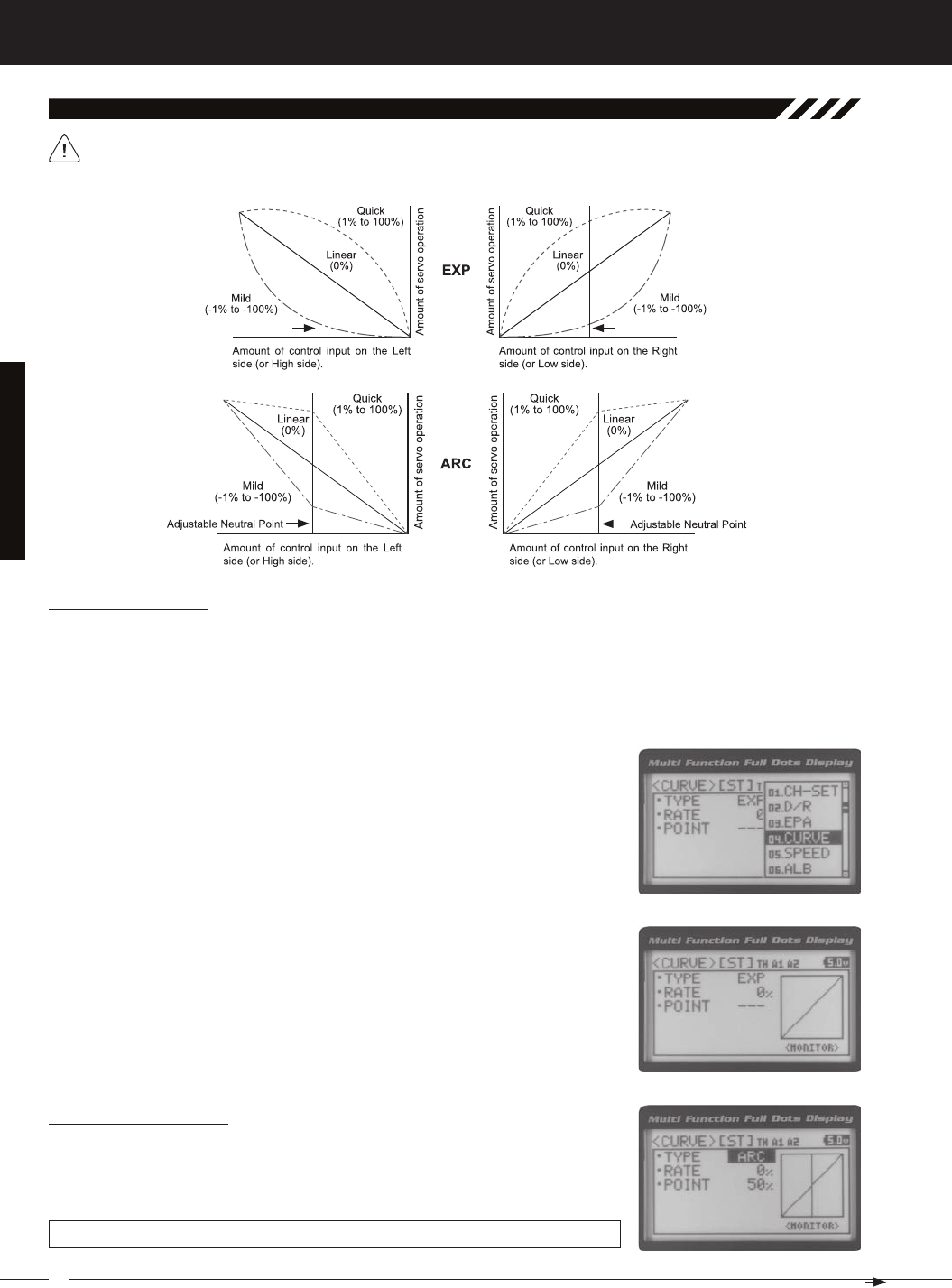
04.Curve (eXPonential and arC adjuStMent)
The Exponential and Adjustable Rate Control (ARC) functions allow you to vary the amount of servo travel in relation
to the movement of the steering wheel, throttle trigger and auxiliary lever near the Neutral positions to change the way
those functions react to control movement. Decreasing the Exponential or Adjustable Rate Control percentage values
will soften the control feel around Neutral and increasing the Exponential or Adjustable Rate Control percentage values
will heighten the control feel around Neutral. Using a lower negative value allows for smoother control. Using a higher
positive value may result in more 'twitchy' control response. The Exponential and Adjustable Rate Control functions can
be adjusted for the Steering channel, the Throttle channel (Throttle High and Throttle Brake), Auxiliary 1 Channel 3 and
22
MT-4S 2.4GHZ FH4T RADIO SYSTEM USER'S GUIDE
T R
[[ProGraMMinG MenuS
04.Curve (eXPonential and arC adjuStMent, Continued....)
Choosing the Channel
Exponential or Adjustable Rate Control percentage values can be adjusted from Mild through Linear to Quick to allow
you to set the most effective control response for your model. For example, if your model over-steers, reduce the Steering
Exponential or Adjustable Rate Control percentage value, and if your model under-steers, increase the Steering Exponen-
tial or Adjustable Rate Control percentage value. As another example, reduce the Throttle Exponential or Adjustable Rate
Control percentage value on a slippery track or with a model that has a higher-torque motor or engine, and increase the
The Exponential and Adjustable Rate Control functions work the same, except the Exponential Rate percentage
value is programmed from a fixed Neutral Point of 50% and the Adjustable Rate Control Rate percentage value is
1) From the TOP screen, press the ENTER key to open the Programming Menu list.
2) Scroll UP or DOWN to highlight the CURVE menu, then press the ENTER key. The
3) Scroll DOWN to move the cursor to the channel you would like to make Program-
ming Value changes to. Choose from <CURVE> [ST] (Steering), <CURVE> [TH]
Choosing the Curve Type
1) Press the ENTER key to highlight TYPE EXP. Press the ENTER key a second time,
then scroll UP or DOWN to choose the desired Curve Type. If you are programming
the Curve function for the Throttle channel, you have the option of adjusting the
CURVE TYPE setting range is EXP and ARC. The default setting is EXP.
23
T R
MT-4S 2.4GHZ FH4T RADIO SYSTEM USER'S GUIDE
[[ProGraMMinG MenuS
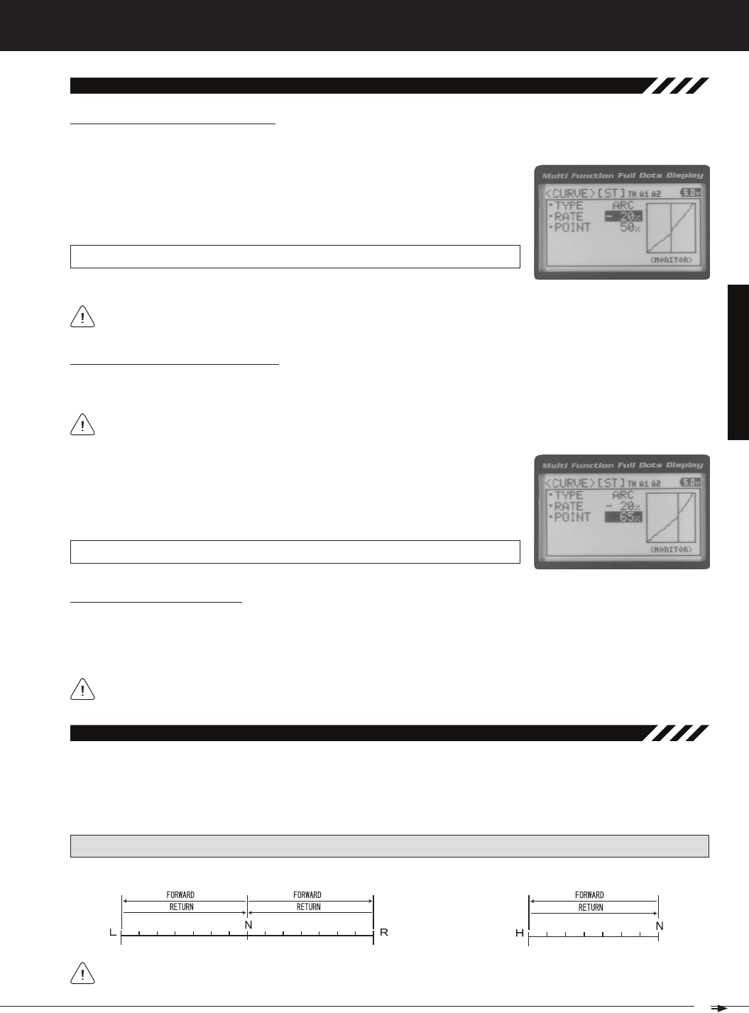
04.Curve (eXPonential and arC adjuStMent, Continued....)
Adjusting the Rate Percentage Value
1) From within the CURVE menu, scroll DOWN to highlight RATE 0%. Press the EN-
TER key, then scroll UP or DOWN to increase or decrease the Rate percentage
value. Using a negative Rate percentage value will soften the control feel around
CURVE RATE setting range is -100% (Mild) to 100% (Quick). The default setting is 0%
Changes to the Rate percentage value affects both the channel High side and Low side equally, except for the
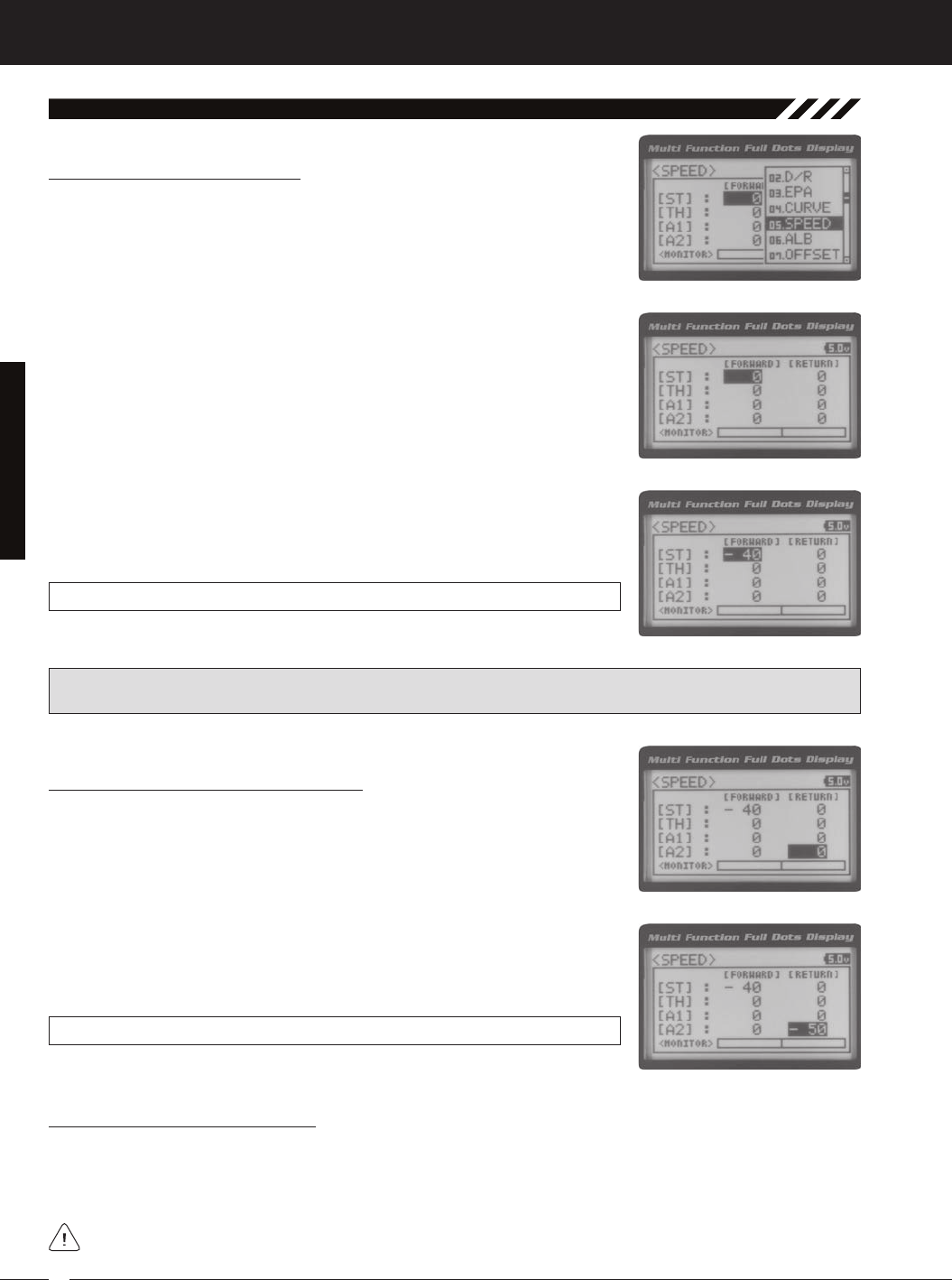
The Servo Speed function allows you to slow the transit speed of the Steering, Throttle, Auxiliary 1 and Auxiliary 2 servos.
Servo transit speed can be slowed in both the Forward and the Return to Neutral directions independently. When driv-
ing your model, proper steering and throttle control are vital. For example, lowering the transit speed of the steering
servo can help to limit excessive steering, which will enable you to achieve smoother cornering. In addition, lowering the
05.SPeed (Servo SPeed)
PRO TIP: Use the Servo Monitor at the bottom of the Speed menu to see your programming changes in virtual real time.
Adjusting the Point Percentage Value
The Point percentage value determines the Neutral Point where the Rate percentage value begins. For example, you
1) From within the CURVE menu, scroll DOWN to highlight POINT 50%. Press the EN-
TER key, then scroll UP or DOWN to increase or decrease the Point percentage
value. Increasing the Point percentage value will shift the Neutral Point to one side
of center and decreasing the Point percentage value will shift the Neutral Point to
CURVE POINT setting range is 5% to 95%. The default setting is 50% (Centered).
Controlling the Curve Function
1) By assigning the Steering, Throttle High and Throttle Brake Rate and Point programming functions to one or more of
the Trim Switches, Auxiliary Lever or Dial Knob, these functions can be adjusted while driving without accessing the
Programming Menu. In addition, the Steering Curve and Throttle Curve functions can be Toggled OFF and ON by as-
24
MT-4S 2.4GHZ FH4T RADIO SYSTEM USER'S GUIDE
T R
[[ProGraMMinG MenuS
3) Scroll UP or DOWN to highlight the desired channel you would like to change the
Forward Speed value for. Choose from either [ST] : FORWARD 0 (Steering),
[TH] : FORWARD 0 (Throttle), [A1] : FORWARD 0 (Auxiliary 1) or [A2] : FORWARD 0
4) Press the ENTER key, then scroll DOWN to decrease servo Speed in the Forward
direction. Decreasing the Forward Speed value will cause the servo transit time
SPEED FORWARD setting range is -100 to 0. The default setting is 0 (Normal
Adjusting the Return to Neutral Speed Value
1) From within the SPEED menu, scroll UP or DOWN to highlight the desired chan-
nel you would like to change the Return to Neutral Speed value for. Choose from
either [ST] : RETURN 0 (Steering), [TH] : RETURN 0 (Throttle), [A1] : RETURN 0
2) Press the ENTER key, then scroll DOWN to decrease servo Speed in the Return
to Neutral direction. Decreasing the Return to Neutral Speed value will cause the
SPEED RETURN setting range is -100 to 0. The default setting is 0 (Normal Speed).
Adjusting the Forward Speed Value
1) From the TOP screen, press the ENTER key to open the Programming Menu list.
2) Scroll UP or DOWN to highlight the SPEED menu, then press the ENTER key. The
05.SPeed (Servo SPeed), Continued....
Controlling the Servo Speed Function
1) By assigning the Steering and Throttle Forward and Return to Neutral Speed programming functions to one or more
of the Trim Switches, Auxiliary Lever or Dial Knob, these functions can be adjusted while driving without accessing the
Programming Menu. In addition, the Steering Speed and Throttle Speed functions can be Toggled OFF and ON by
IMPORTANT: Throttle Servo Speed affects only the Throttle High Side. The Throttle Brake Side is unaffected. See
Throttle diagram on previous page.
25
T R
MT-4S 2.4GHZ FH4T RADIO SYSTEM USER'S GUIDE
[[ProGraMMinG MenuS
The Anti-Lock Braking function makes it possible to achieve stable braking even on a slippery surface. With stable brak-
ing, your model is better able to trace an exact line under braking. The Anti-Lock Braking function also enables you to set
different braking characteristics depending on your particular model. Different Anti-Lock Braking function options can
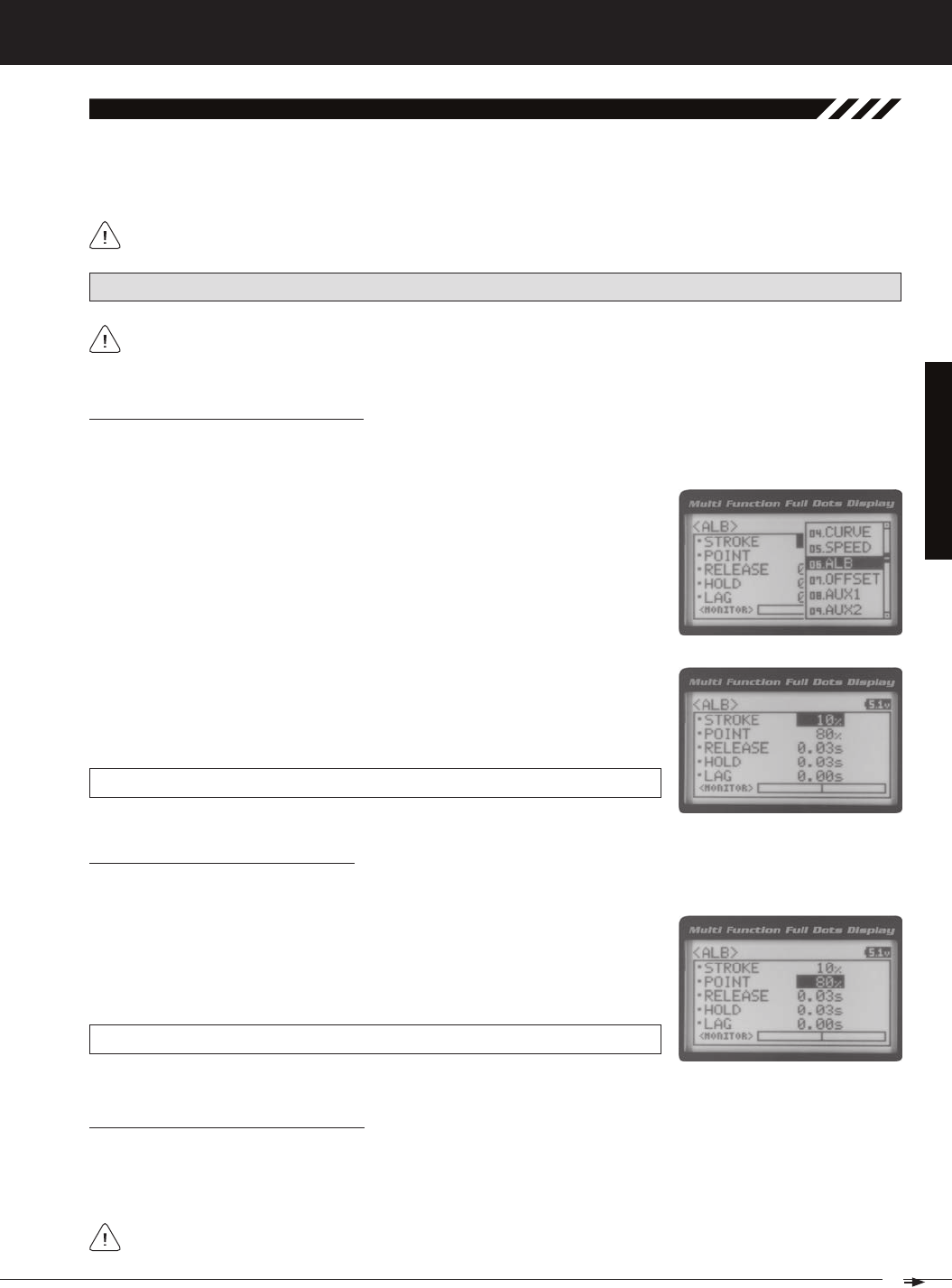
06.alb (anti-loCk brakinG)
The Anti-Lock Braking function operates only when the throttle trigger is moved from Neutral to the Brake side. Set
the hardest braking you can obtain from your model by carefully setting the Anti-Lock Braking function at the point
PRO TIP: Use the Servo Monitor at the bottom of the ALB menu to see your programming changes in virtual real time.
1) From the TOP screen, press the ENTER key to open the Programming Menu list.
2) Scroll UP or DOWN to highlight the ALB menu, then press the ENTER key. The
Adjusting the Stroke Percentage Value
The Stroke percentage value determines the amount of Brake that's applied automatically when the Anti-Lock Braking
function Activates. When set to OFF, the Anti-Lock Braking function will not work. A percentage value of 1% or greater
3) Press the ENTER key, then scroll UP or DOWN to increase or decrease the Stroke
percentage value. Increasing the Stroke percentage value will increase throttle
servo travel in the Brake direction and decreasing the Stroke percentage value
ALB STROKE setting range is OFF to 100%. The default setting is OFF.
Adjusting the Point Percentage Value
1) From within the ALB menu, scroll DOWN to highlight POINT 80%. Press the EN-
TER key, then scroll UP or DOWN to increase or decrease the Point percentage
value. Increasing the Point percentage value will cause the Anti-Lock Braking
function to Activate later and decreasing the Point percentage value will cause
ALB POINT setting range is 5% to 100%. The default setting is 80%.
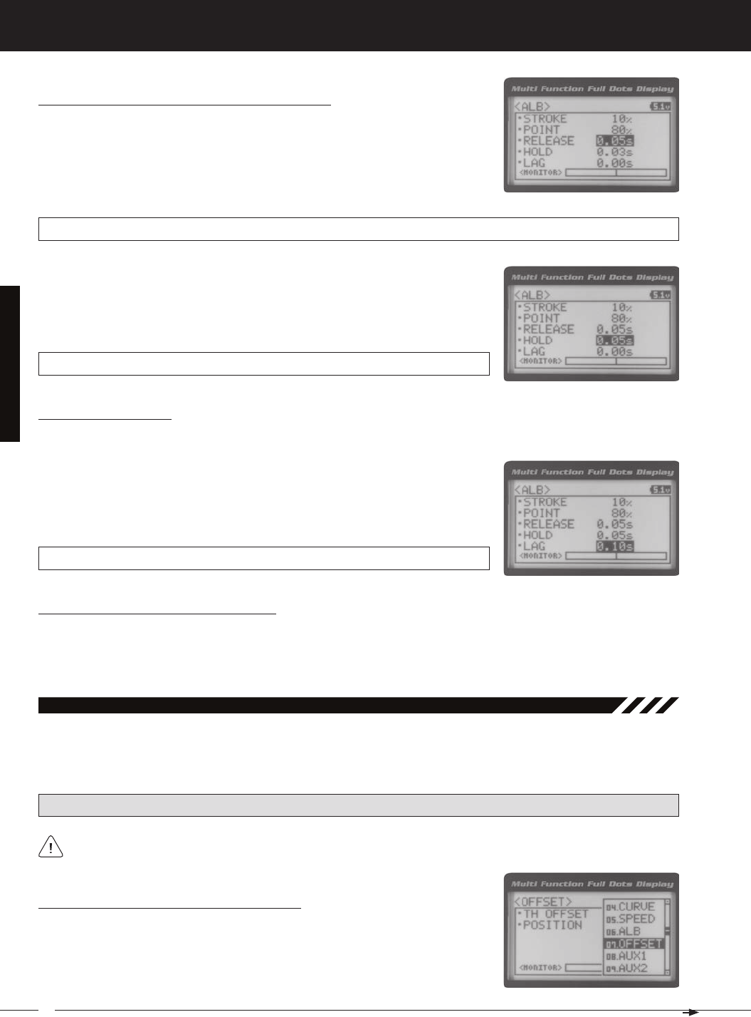
Adjusting the Release and Hold Values
The Release and Hold values determine the speed at which the brake pulsates. By adjusting the Release and Hold val-
ues, you can make the brake pulsate faster or slower. The Release value determines how quickly the Brake moves from
Neutral to the percentage value determined by the Stroke setting and the Hold value determines how quickly the Brake
We recommend using equal Release and Hold values, although different values can be used to fine-tune how
26
MT-4S 2.4GHZ FH4T RADIO SYSTEM USER'S GUIDE
T R
Adjusting the Lag Value
1) From within the ALB menu, scroll DOWN to highlight LAG 0.00s. Press the ENTER
key, then scroll UP and DOWN to increase or decrease the Lag value. Increasing
the Lag value increases the delay time to Activate the Anti-Lock Braking func-
tion after reaching the Point setting and decreasing the Lag value decreases
ALB LAG setting range is 0.00s to 1.00s. The default setting is 0.00s.
Controlling the Anti-Lock Braking Function
1) By assigning the Anti-Lock Braking Point, Stroke, Lag, Hold and Release programming functions to one or more of
the Trim Switches, Auxiliary Lever or Dial Knob, these functions can be adjusted while driving without accessing the
Programming Menu. In addition, the Anti-Lock Braking function can be Toggled OFF and ON by assigning it to one of
[[ProGraMMinG MenuS
Adjusting the Release and Hold Values, Continued....
1) From within the ALB menu, scroll DOWN to highlight RELEASE 0.03s. Press the
ENTER key, then scroll UP or DOWN to increase or decrease the Release value.
Increasing the Release value will cause the Brake to move from Neutral to the
Stroke setting slower and decreasing the Release value will cause the Brake to
ALB RELEASE setting range is 0.01s to 1.00s. The default setting is 0.03s.
2) From within the ALB menu, scroll DOWN to highlight HOLD 0.03s. Press the ENTER
key, then scroll UP or DOWN to increase or decrease the Hold value. Increasing
the Hold value will cause the Brake to move from the Stroke setting to the Neutral
position slower and decreasing the Hold value will cause the Brake to move from
ALB HOLD setting range is 0.01s to 1.00s. The default setting is 0.03s.
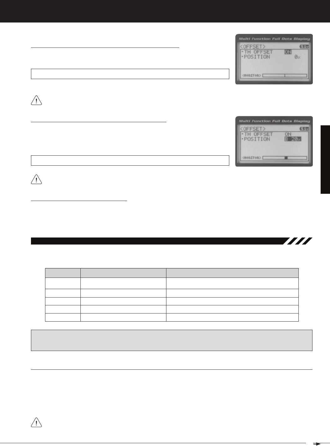
The Throttle Offset function allows you to shift the Neutral position of the throttle servo, either toward the High Side or the
Brake Side. When used in conjunction with a Push-Button Switch, this function can be used several different ways. For
example, if you're driving a glow- or gas-powered model, you can program the Throttle Offset function to shut down your
07.offSet (tHrottle offSet)
PRO TIP: Use the Servo Monitor at the bottom of the OFFSET menu to see your programming changes in virtual real
Turning the Throttle Offset Function ON or OFF
1) From the TOP screen, press the ENTER key to open the Programming Menu list.
2) Scroll UP or DOWN to highlight the OFFSET menu, then press the ENTER key. The
27
T R
MT-4S 2.4GHZ FH4T RADIO SYSTEM USER'S GUIDE
[[ProGraMMinG MenuS
Turning the Throttle Offset Function ON or OFF, Continued....
3) Press the ENTER key, then scroll UP or DOWN to change the Throttle Offset value
OFFSET TH OFFSET setting range is OFF to ON. The default setting is OFF.
Although the Throttle Offset value is set to ON, the Throttle Offset function will not operate until a Position percent-
Adjusting the Throttle Offset Position Percentage Value
1) From within the OFFSET menu, scroll DOWN to highlight POSITION 0%. Press the
ENTER key, then scroll UP to shift the throttle servo Neutral position the desired
amount toward the Throttle High Side or scroll DOWN to shift the throttle servo
OFFSET POSITION setting range is H100% to B100%. The default setting is 0%.
When a Position percentage value is programmed and the Throttle Offset function is Active, LED 1 (Blue) will flash
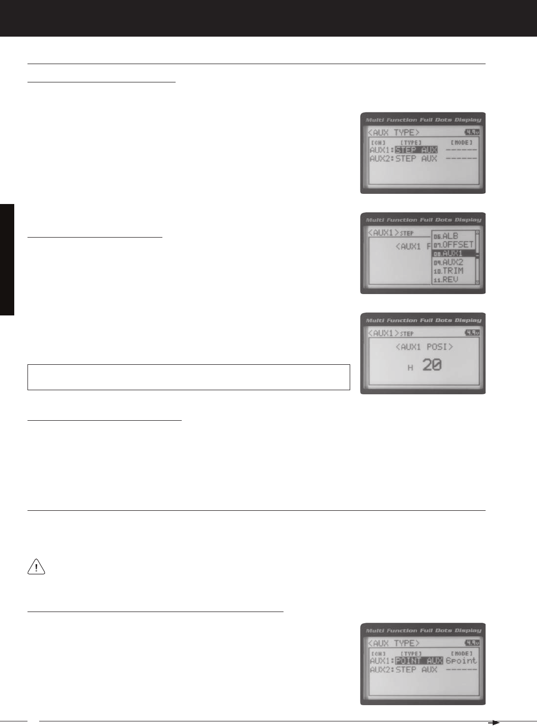
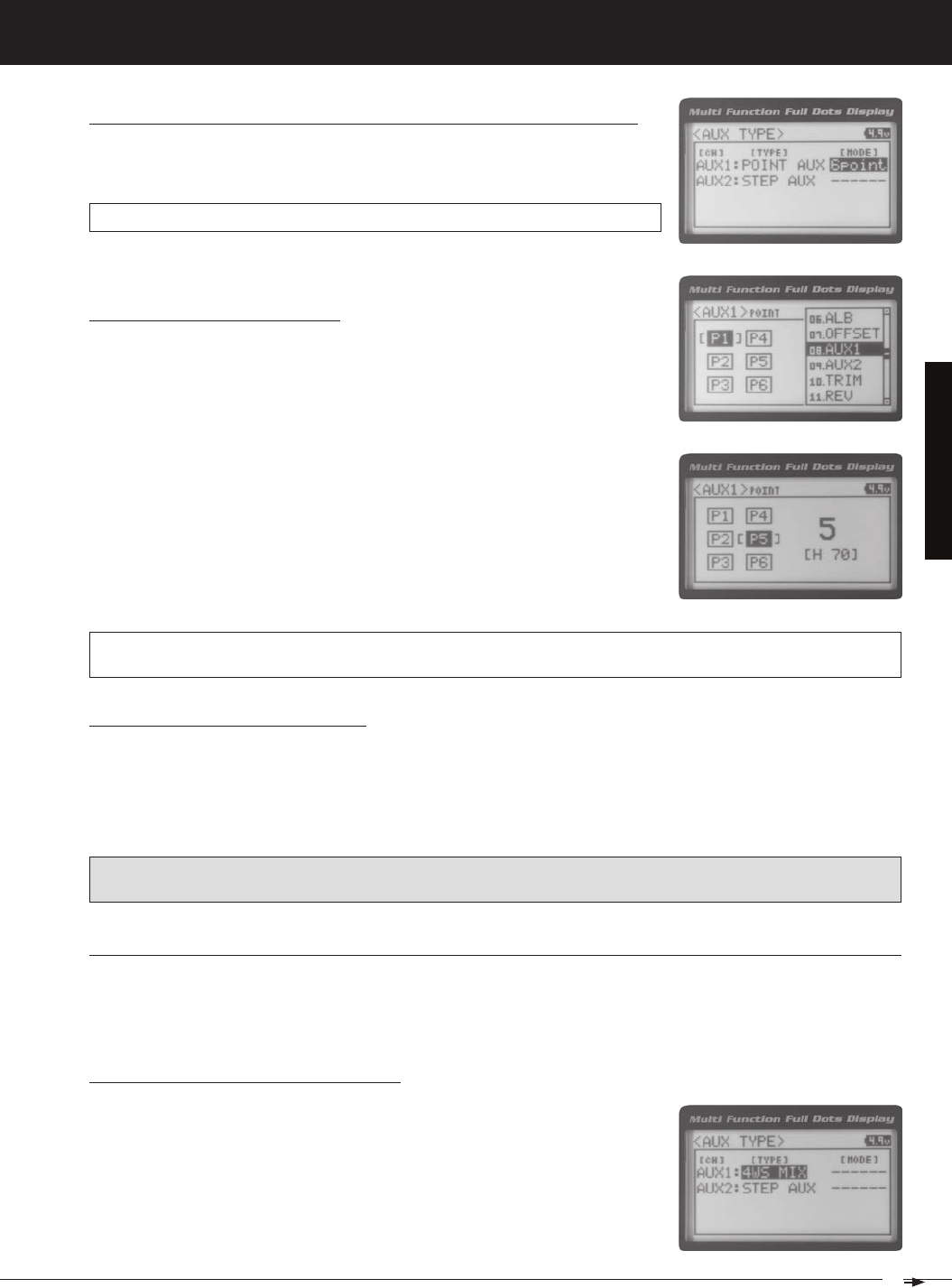
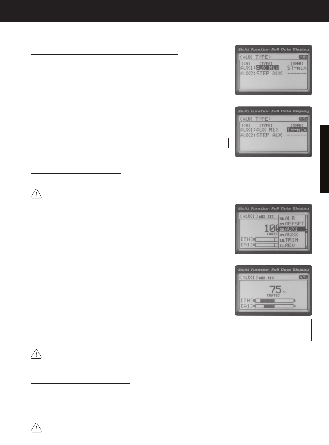
The Auxiliary 1 Programming function allows you to program the five different Auxiliary Programming functions that are
08.auX1 (auXiliary 1 ProGraMMinG)
S _ A U X
P _ A U X
4WS
MOA
Step Auxiliary
Point Auxiliary
Four Wheel Steering Mixing
Motor On Axle Dual Throttle Mixing
Controls Step Values That the Auxiliary Servo Travels
Controls Specific Points That the Auxiliary Servo Travels
Controls Four Wheel Steering Options
Controls Dual Throttle Options
IMPORTANT: Prior to programming an Auxiliary 1 Programming function you must first choose the desired Auxil-
iary Programming function in the SYSTEM AUX TYPE menu. Only one Auxiliary 1 Programming function can be Active
at any given time.
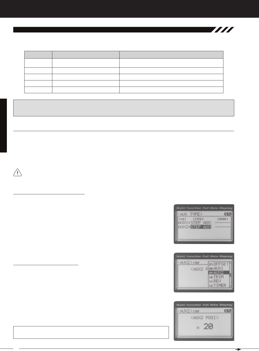
The Step Auxiliary function allows you to program the Auxiliary 1 servo to move a defined amount when toggled ON and
OFF using a Push-Button Switch. For example, if you assign Auxiliary 1 to a Push-Button Switch, then program the Step
Auxiliary percentage value to 50%, the Auxiliary 1 servo will travel from the Neutral position to 50% of travel when the
Push-Button Switch is pressed. Press the Push-Button switch a second time and the Auxiliary 1 servo will travel back to
the Neutral position. This is useful to control simple ON/OFF functions, such as a reverse servo for a transmission or a
Controlling the Throttle Offset Function
1) By assigning the Throttle Offset Position programming function to one of the Trim Switches, Auxiliary Lever or Dial
Knob, this function can be adjusted while driving without accessing the Programming Menu. In addition, the Throttle
Offset function can be Toggled OFF and ON by assigning it to one of the Push-Button Switches. For more information,
The Step Auxiliary Position value can be adjusted while you're driving using one of the four Trim Switches, the
Rotary Dial or the Auxiliary Lever. The Step Auxiliary function can be toggled OFF and ON by assigning Auxiliary 1
SteP (SteP auXiliary)
28
MT-4S 2.4GHZ FH4T RADIO SYSTEM USER'S GUIDE
T R
[[ProGraMMinG MenuS
SteP (SteP auXiliary), Continued....
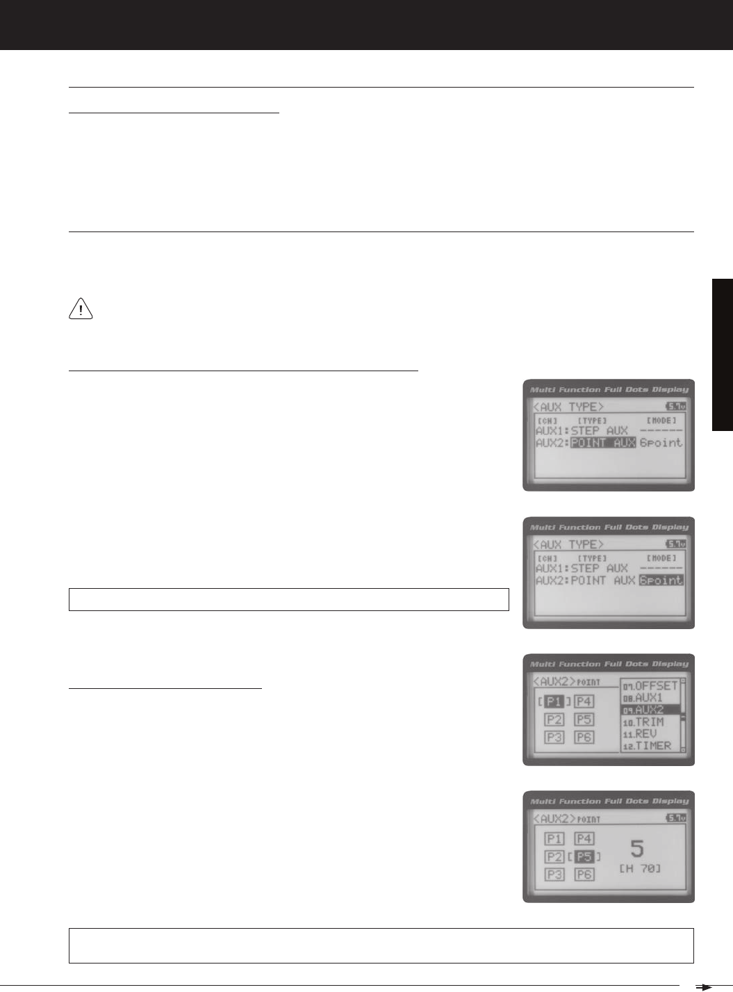
Point (Point auXiliary)
The Point Auxiliary function allows you to program the Auxiliary 1 servo to move up to 6 different Points along its travel,
then cycle through those Points using one of the Trim Switches or the Rotary Dial. For example, if your model requires
Adjusting the Step Auxiliary Value
1) From the TOP screen, press the ENTER key to open the Programming Menu list.
2) Scroll UP or DOWN to highlight the AUX1 menu, then press the ENTER key. The
3) Press the ENTER key, then scroll UP or DOWN to change the Auxiliary 1 Position
value. Increasing the value toward the High side (H) or Low side (L) will cause
the Auxiliary 1 servo to travel to that specific position when you Activate the Auxil-
AUX1 STEP AUX1 POSI setting range is H100 to L100. The default setting is 0. This
value is a percentage of Auxiliary 1 servo travel.
2) Scroll UP or DOWN to highlight the SYSTEM menu, then press the ENTER key.
Scroll DOWN to highlight the AUX TYPE menu, then press the ENTER key.
3) Press the ENTER key, then scroll UP or DOWN to choose the AUX 1: STEP AUX
Choosing the Step Auxiliary Function
Use one of the four Trim Switches or the Rotary Dial to cycle through the Point positions while you're driving. The
Point Auxiliary function can be toggled OFF and ON while you're driving by assigning Auxiliary 1 to one of the two
2) Scroll UP or DOWN to highlight the SYSTEM menu, then press the ENTER key.
Scroll DOWN to highlight the AUX TYPE menu, then press the ENTER key.
3) Press the ENTER key, then scroll UP or DOWN to choose the AUX 1: POINT AUX
Choosing the Point Auxiliary Function and the Number of Points
Controlling the Step Auxiliary Function
1) In the default configuration, Auxiliary 1 is controlled by the Rotary Dial which allows the Step Auxiliary function to be
adjusted while driving without accessing the Programming Menu. Turn the Rotary Dial clockwise to increase the Posi-
tion High Side value and turn the Rotary Dial counter-clockwise to increase the Position Low Side value. In addition,
Auxiliary 1 can be assigned to one of the four Trim Switches or the Auxiliary Lever. The Step Auxiliary function can
be toggled OFF and ON by assigning Auxiliary 1 to one of the two Push-Button Switches. This allows you to control
29
T R
MT-4S 2.4GHZ FH4T RADIO SYSTEM USER'S GUIDE
[[ProGraMMinG MenuS
Choosing the Point Auxiliary Function and the Number of Points, Continued....
4) From within the AUX TYPE menu, scroll DOWN to highlight [MODE] 6 POINT.
Press the ENTER key, then scroll UP or DOWN to choose the desired number of
AUX TYPE POINT setting range is 2point to 6point. The default setting is 6point.
Adjusting the Point Auxiliary Values
1) From the TOP screen, press the ENTER key to open the Programming Menu list.
2) Scroll UP or DOWN to highlight the AUX1 menu, then press the ENTER key. The
3) Scroll UP or DOWN to move the brackets to the Point you would like to change,
then press the ENTER key to highlight that Point.
4) Press the ENTER key, then scroll UP or DOWN to change the Point value. Increas-
ing the Point value toward the High side (H) or Low side (L) will cause the Auxil-
iary 1 servo to travel to that specific position when you cycle through the various
Points.
AUX1 POINT setting range is H100 to L100. The default setting for Point 1 is L100, for Point 2 is L60, for Point 3 is L20,
for Point 4 is H20, for Point 5 is H60, and for Point 6 is H100. These values are a percentage of Auxiliary 1 servo travel.
Controlling the Point Auxiliary Function
1) In the default configuration, Auxiliary 1 is controlled by the Rotary Dial. Turn the Rotary Dial clockwise to cycle For-
ward through the programmed Point Auxiliary positions and turn the Rotary Dial counter-clockwise to cycle Backward
through the programmed Point Auxiliary positions. The Auxiliary 1 servo will move to the specified Point positions as
you cycle through the different Points. In addition, Auxiliary 1 can be assigned to one of the four Trim Switches. The Point
Auxiliary function can be toggled OFF and ON by assigning Auxiliary 1 to one of the two Push-Button Switches. For
IMPORTANT: To operate correctly, the TRIM or DIAL Step value must be set to 1. If set to a value other than 1, Point
positions will be skipped as you cycle through them. For more information, see the Key Assignments section on pages
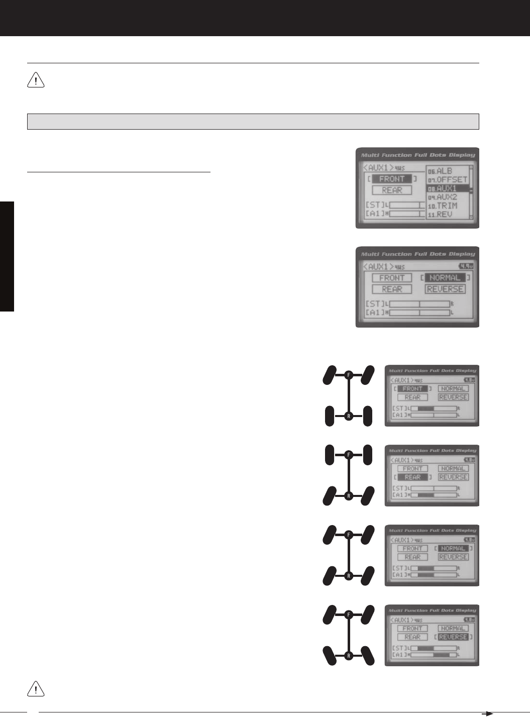
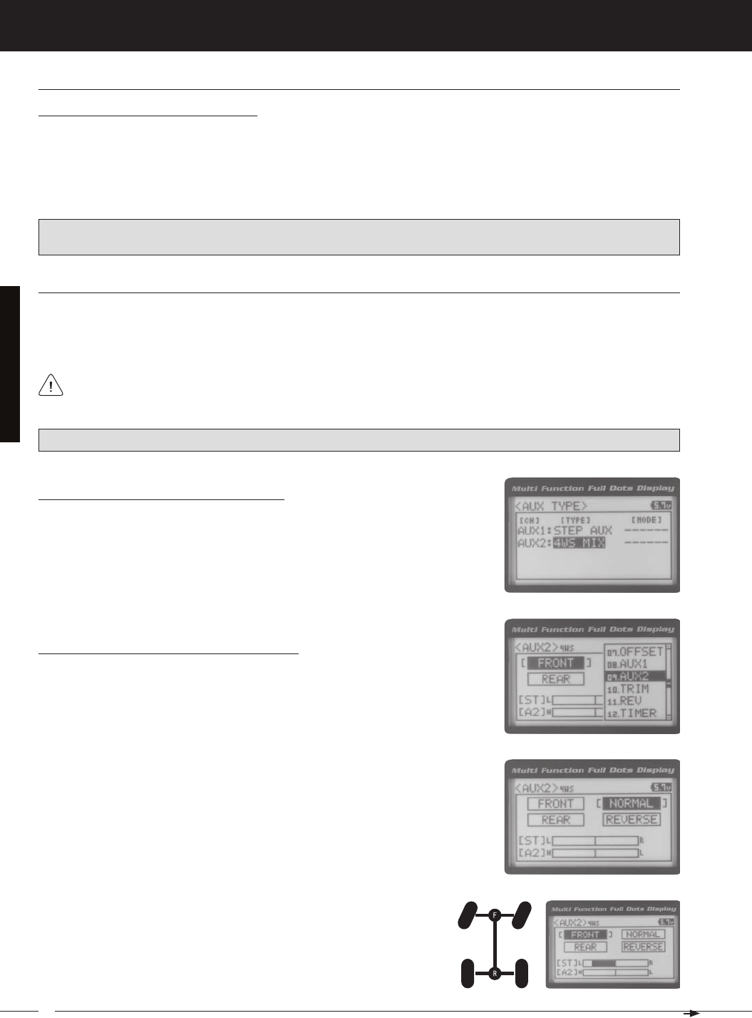
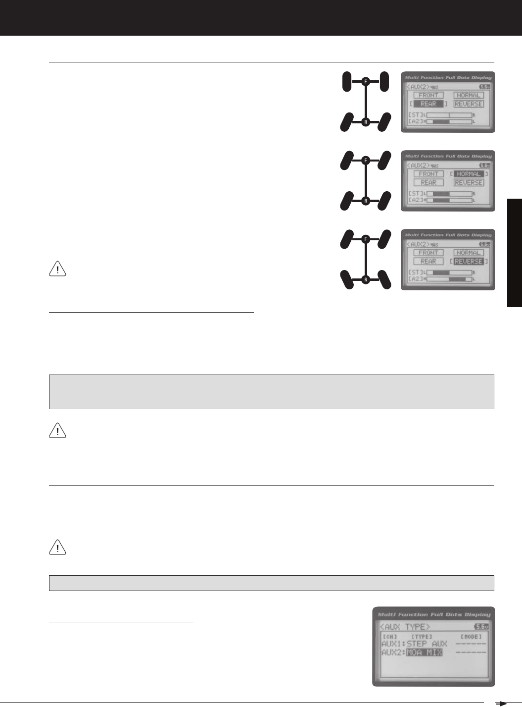
4wS (four wHeel SteerinG MiXinG)
The Four Wheel Steering Mixing function allows you to use Auxiliary 1 Channel 3 as a second steering channel, allowing
you to use two separate steering servos for Front and Rear steering. The Four Wheel Steering Mixing function allows you
to control either the Front or Rear steering independently, or Mix the Front and Rear steering to have Parallel Four Wheel
2) Scroll UP or DOWN to highlight the SYSTEM menu, then press the ENTER key.
Scroll DOWN to highlight the AUX TYPE menu, then press the ENTER key.
Choosing the Four Wheel Steering Function
30
MT-4S 2.4GHZ FH4T RADIO SYSTEM USER'S GUIDE
T R
[[ProGraMMinG MenuS
Choosing Four Wheel Steering Mixing Options
1) From the TOP screen, press the ENTER key to open the Programming Menu list.
2) Scroll UP or DOWN to highlight the AUX1 menu, then press the ENTER key. The
3) Scroll UP or DOWN to move the brackets to the Four Wheel Steering option you
would like to use, then press the ENTER key to highlight that option. The high-
PRO TIP: Use the Servo Monitor at the bottom of the AUX 1 4WS menu to see your programming changes in virtual real
Parallel (Normal) Four Wheel Steering - When highlighted, both the Front
Tandem (Reverse) Four Wheel Steering - When highlighted, both the
If the steering servos do not operate as described above, you can use the Servo Reversing function to change the
4wS (four wHeel SteerinG MiXinG), Continued....
Use the Rotary Dial or one of the four Trim Switches to cycle through the different Four Wheel Steering options
while you're driving. The Four Wheel Steering Mixing function can be toggled OFF and ON while you're driving
31
T R
MT-4S 2.4GHZ FH4T RADIO SYSTEM USER'S GUIDE
[[ProGraMMinG MenuS
Controlling the Four Wheel Steering Mixing Function
1) In the default configuration, Auxiliary 1 is controlled by the Rotary Dial. Turn the Rotary Dial clockwise to cycle Forward
through the Four Wheel Steering options (FRONT > REAR > NORMAL > REVERSE) and turn the Rotary Dial counter-
clockwise to cycle Backward through the Four Wheel Steering options (REVERSE > NORMAL > REAR > FRONT). In
addition, Auxiliary 1 can be assigned to one of the four Trim Switches. The Four Wheel Steering Mixing function can
be toggled OFF and ON by assigning Auxiliary 1 to one of the two Push-Button Switches. For more information, see
IMPORTANT: To operate correctly, the DIAL or TRIM Step value must be set to 1. If set to a value other than 1, Four
Wheel Steering Mixing options will be skipped as you cycle through them. For more information, see the Key Assign-
ments section on pages 56 ~ 61.
When using Four Wheel Steering, it's important to adjust the Steering Channel 1 and Auxiliary 1 Channel 3 Sub-
Trim values to center both servos. This will ensure that your model tracks straight. In addition, remember that you
are able to independently adjust the Auxiliary 1 Channel 3 Dual Rate, Exponential, Sub-Trim, Servo Speed settings and
4wS (four wHeel SteerinG MiXinG), Continued....
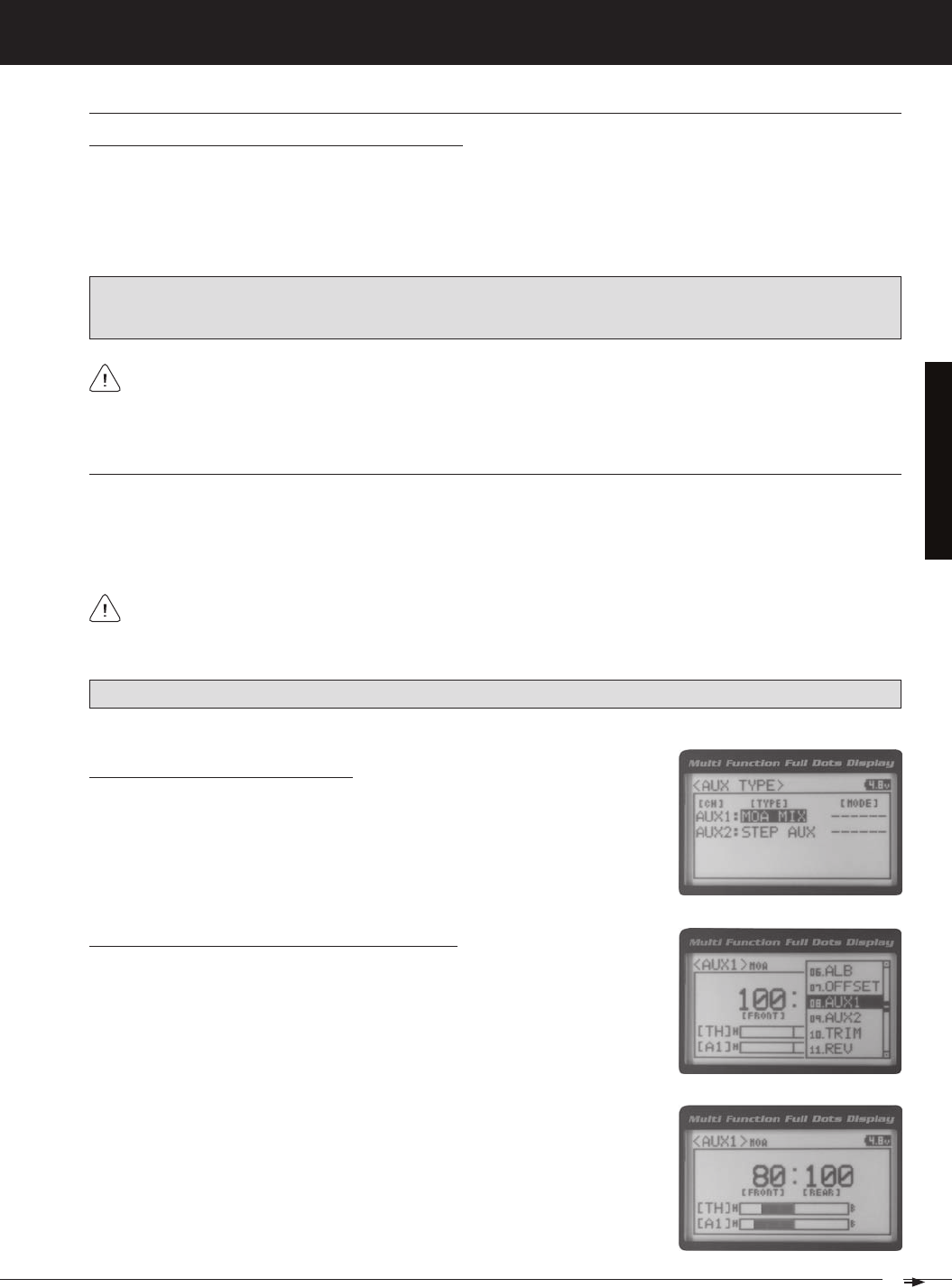
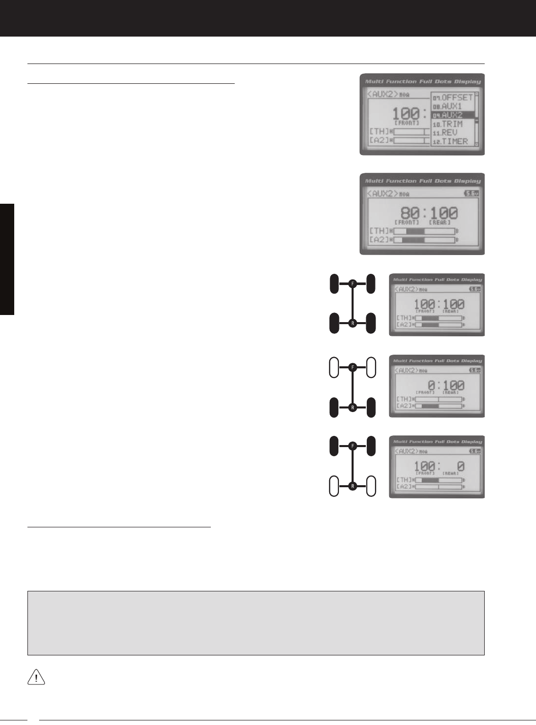
Moa (Motor on aXle MiXinG)
The Motor on Axle Mixing function allows you to use Auxiliary 1 Channel 3 as a second throttle channel, allowing you to
use two separate throttle servos or ESCs. The Motor on Axle Mixing function is typically used in Rock Crawling and allows
you to control either the Front and Rear motors together or independently, giving you Normal (Balanced), Dig and Burn
functions. And when
coupled with the ability to variably change the power distribution between the Front and Rear mo-
Choosing the Motor on Axle Function
1) From the TOP screen, press the ENTER key to open the Programming Menu list.
2) Scroll UP or DOWN to highlight the SYSTEM menu, then press the ENTER key.
Scroll DOWN to highlight the AUX TYPE menu, then press the ENTER key.
Changing Motor on Axle Power Distribution Options
You are able to program Normal (Balanced), Dig and Burn functions by changing
the Power Distribution between the two motors.
1) From the TOP screen, press the ENTER key to open the Programming Menu list.
2) Scroll UP or DOWN to highlight the AUX1 menu, then press the ENTER key. The
PRO TIP: Use the Servo Monitor at the bottom of the AUX 1 MOA menu to see your programming changes in virtual real
3) Press the ENTER key, then scroll UP or DOWN to change the Power Distribution
between the Front and Rear motors. Scrolling UP will reduce the available power
Use the Rotary Dial, one of the four Trim Switches or the Auxiliary Lever to Activate the Dig and Burn functions while
you're driving. The Motor on Axle Mixing function can be toggled OFF and ON while you're driving by assigning
32
MT-4S 2.4GHZ FH4T RADIO SYSTEM USER'S GUIDE
T R
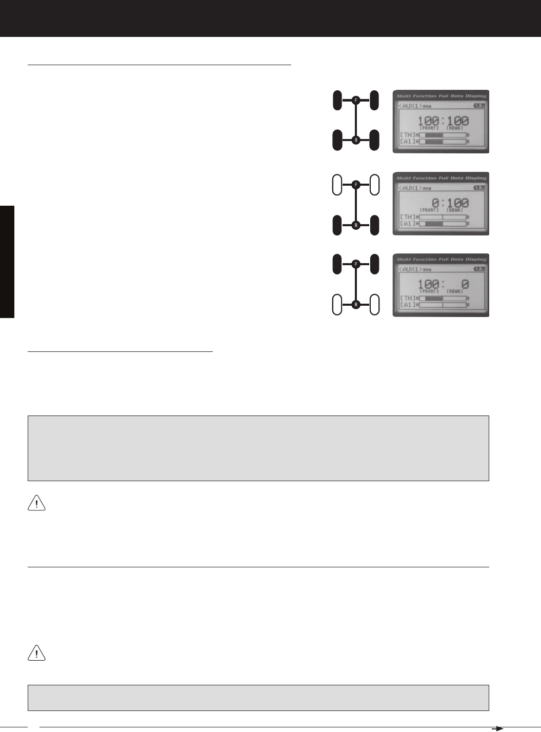
Front Throttle BURN - When set to 0:100, power will only be distributed to
the Rear motor (Burn). Power can be distributed proportionally between the
Rear Throttle DIG - When set to 100:0, power will only be distributed to the
Front motor (Dig). Power can be distributed proportionally between the
Normal (Balanced) - When set to 100:100, power will be evenly distributed
[[ProGraMMinG MenuS
Changing Motor on Axle Power Distribution Options, Continued....
Controlling the Motor on Axle Mixing Function
1) In the default configuration, Auxiliary 1 is controlled by the Rotary Dial. Turn the Rotary Dial clockwise to reduce the
available power to the Rear motor (Dig) and turn the Rotary Dial counter-clockwise to reduce the power to the Front
motor (Burn). In addition, Auxiliary 1 can be assigned to one of the four Trim Switches or to the Auxiliary Lever. The
Motor on Axle Mixing function can be toggled OFF and ON by assigning Auxiliary 1 to one of the two Push-Button
IMPORTANT: In the default configuration, the Rotary Dial Step value is set to 5. This allows you to adjust the Power Distri-
bution in 5 percent increments. If you prefer to control the Dig and Burn functions as if they were assigned to an ON/
OFF switch, change the DIAL Step value to 100. Alternately, the Motor on Axle Mixing function can be controlled by
the Auxiliary Lever. This allows you to quickly switch between the Dig and Burn functions and still have the ability to
variably change the Power Distribution between the Front and Rear motors. To set this up, change the Auxiliary Lever
Function to AUX1, then change the TWEAK (H) value to +100 and the TWEAK (L) value to -100. For more information,
When using the Motor on Axle function, it's important to adjust the Throttle Channel 2 and Auxiliary 1 Channel 3
Sub-Trim values so both motors' idle (or OFF) settings are equal. This will ensure correct function. In addition,
remember that you are able to independently adjust the Auxiliary 1 Channel 3 Dual Rate, Exponential, Sub-Trim, Servo
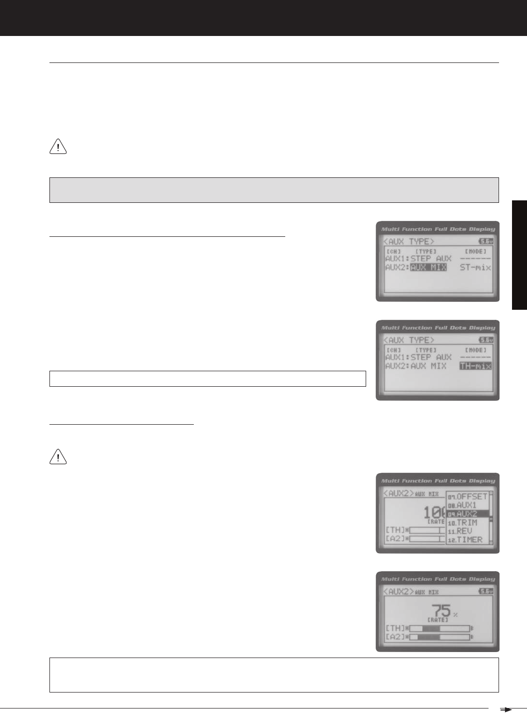
auX MiX (auXiliary MiXinG)
The Auxiliary Mixing function allows you to Mix either Steering Channel 1 or Throttle Channel 2 to Auxiliary 1 Channel 3,
while maintaining separate Sub-Trim, End Point Adjustments, Servo Reversing and other channel-specific settings.
The Auxiliary Mixing function is used when a custom Mix is necessary. For example, if your monster truck features dual
Front steering servos, instead of using a Y-Harness to join the two steering servos together, you can use Steering Mixing
to operate both steering servos together and still be able to make adjustments to each servo separately. In addition, if
The Auxiliary Mixing Rate percentage value can be adjusted while you're driving using one of the four Trim
Switches, the Rotary Dial or the Auxiliary Lever. The Auxiliary Mixing function can be toggled OFF and ON while
PRO TIP: Use the Servo Monitor at the bottom of the AUX 1 AUX MIX menu to see your programming changes in virtual
real time.
33
T R
MT-4S 2.4GHZ FH4T RADIO SYSTEM USER'S GUIDE
[[ProGraMMinG MenuS
Choosing the Auxiliary Mixing Function and the Mixing Type
1) From the TOP screen, press the ENTER key to open the Programming Menu list.
2) Scroll UP or DOWN to highlight the SYSTEM menu, then press the ENTER key.
Scroll DOWN to highlight the AUX TYPE menu, then press the ENTER key.
4) From within the AUX TYPE menu, scroll DOWN to highlight [MODE] ST-mix. Press
the ENTER key, then scroll UP or DOWN to choose the desired Mixing type you
AUX TYPE MIX setting range is ST-mix and TH-mix. The default setting is ST-mix.
Adjusting the Rate Percentage Value
1) From the TOP screen, press the ENTER key to open the Programming Menu list.
2) Scroll UP or DOWN to highlight the AUX1 menu, then press the ENTER key. The
3) Press the ENTER key, then scroll UP or DOWN to change the Rate percentage
value. Decreasing the Rate percentage value will reduce the amount the Auxiliary
1 servo travels relative to the Steering servo or Throttle servo and increasing
the Rate percentage value will increase the amount the Auxiliary 1 servo travels
AUX1 AUX MIX RATE setting range is 100% to 0%. The default setting is 100%. This Mix is Linear. For example, if the Rate
percentage value is set to 100%, the Auxiliary 1 servo will travel the same amount as the Steering servo. Additionally, if
the Rate percentage value is set to 50%, the Auxiliary 1 servo will travel half the amount as the Steering servo.
The Master channel (either Steering Channel 1 or Throttle Channel 2) always controls the Slave channel (Auxil-
Controlling the Auxiliary Mixing Function
1) In the default configuration, Auxiliary 1 is controlled by the Rotary Dial. Turn the Rotary Dial clockwise to increase the
Rate percentage value and turn the Rotary Dial counter-clockwise to decrease the Rate percentage value. In addition,
the Auxiliary Mixing Rate function can be assigned to one of the four Trim Switches or the Auxiliary Lever. The Auxiliary
Mixing function can be toggled OFF and ON by assigning Auxiliary 1 to one of the two Push-Button Switches. For
auX MiX (auXiliary MiXinG), Continued....
In the default configuration, the Auxiliary 1 servo will travel in the same direction as the Steering servo or Throttle
servo. To apply the Mix in the opposite direction, change the Servo Reversing value of Auxiliary 1 Channel 3. For
Remember that you are able to independently adjust the Auxiliary 1 Channel 3 Dual Rate, Exponential, Sub-Trim,
34
MT-4S 2.4GHZ FH4T RADIO SYSTEM USER'S GUIDE
T R
[[ProGraMMinG MenuS
The Auxiliary 2 Programming function allows you to program the five different Auxiliary Programming functions that are
09.auX2 (auXiliary 2 ProGraMMinG)
S _ A U X
P _ A U X
4WS
MOA
Step Auxiliary
Point Auxiliary
Four Wheel Steering Mixing
Motor On Axle Dual Throttle Mixing
Controls Step Values That the Auxiliary Servo Travels
Controls Specific Points That the Auxiliary Servo Travels
Controls Four Wheel Steering Options
Controls Dual Throttle Options
IMPORTANT: Prior to programming an Auxiliary 2 Programming function you must first choose the desired Auxil-
iary Programming function in the SYSTEM AUX TYPE menu. Only one Auxiliary 2 Programming function can be Active
at any given time.
The Step Auxiliary function allows you to program the Auxiliary 2 servo to move a defined amount when toggled ON and
OFF using a Push-Button Switch. For example, if you assign Auxiliary 2 to a Push-Button Switch, then program the Step
Auxiliary percentage value to 50%, the Auxiliary 2 servo will travel from the Neutral position to 50% of travel when the
Push-Button Switch is pressed. Press the Push-Button switch a second time and the Auxiliary 2 servo will travel back to
the Neutral position. This is useful to control simple ON/OFF functions, such as a reverse servo for a transmission or a
The Step Auxiliary Position value can be adjusted while you're driving using one of the four Trim Switches, the
Rotary Dial or the Auxiliary Lever. The Step Auxiliary function can be toggled OFF and ON by assigning Auxiliary 2
SteP (SteP auXiliary)
Adjusting the Step Auxiliary Value
1) From the TOP screen, press the ENTER key to open the Programming Menu list.
2) Scroll UP or DOWN to highlight the AUX2 menu, then press the ENTER key. The
3) Press the ENTER key, then scroll UP or DOWN to change the Auxiliary 2 Position
value. Increasing the value toward the High side (H) or Low side (L) will cause
the Auxiliary 2 servo to travel to that specific position when you Activate the Auxil-
AUX2 STEP AUX2 POSI setting range is H100 to L100. The default setting is 0. This
value is a percentage of Auxiliary 2 servo travel.
2) Scroll UP or DOWN to highlight the SYSTEM menu, then press the ENTER key.
Scroll DOWN to highlight the AUX TYPE menu, then press the ENTER key.
3) Press the ENTER key, then scroll UP or DOWN to choose the AUX 2: STEP AUX
Choosing the Step Auxiliary Function
35
T R
MT-4S 2.4GHZ FH4T RADIO SYSTEM USER'S GUIDE
[[ProGraMMinG MenuS
Controlling the Step Auxiliary Function
1) In the default configuration, Auxiliary 2 is controlled by the Rotary Dial which allows the Step Auxiliary function to be
adjusted while driving without accessing the Programming Menu. Turn the Rotary Dial clockwise to increase the Posi-
tion High Side value and turn the Rotary Dial counter-clockwise to increase the Position Low Side value. In addition,
Auxiliary 2 can be assigned to one of the four Trim Switches or the Auxiliary Lever. The Step Auxiliary function can
be toggled OFF and ON by assigning Auxiliary 2 to one of the two Push-Button Switches. This allows you to control
SteP (SteP auXiliary), Continued....
Point (Point auXiliary)
The Point Auxiliary function allows you to program the Auxiliary 2 servo to move up to 6 different Points along its travel,
then cycle through those Points using one of the Trim Switches or the Rotary Dial. For example, if your model requires
Use one of the four Trim Switches or the Rotary Dial to cycle through the Point positions while you're driving. The
Point Auxiliary function can be toggled OFF and ON while you're driving by assigning Auxiliary 2 to one of the two
2) Scroll UP or DOWN to highlight the SYSTEM menu, then press the ENTER key.
Scroll DOWN to highlight the AUX TYPE menu, then press the ENTER key.
3) Press the ENTER key, then scroll UP or DOWN to choose the AUX 2: POINT AUX
Choosing the Point Auxiliary Function and the Number of Points
4) From within the AUX TYPE menu, scroll DOWN to highlight [MODE] 6 POINT.
Press the ENTER key, then scroll UP or DOWN to choose the desired number of
AUX TYPE POINT setting range is 2point to 6point. The default setting is 6point.
Adjusting the Point Auxiliary Values
1) From the TOP screen, press the ENTER key to open the Programming Menu list.
2) Scroll UP or DOWN to highlight the AUX1 menu, then press the ENTER key. The
3) Scroll UP or DOWN to move the brackets to the Point you would like to change,
then press the ENTER key to highlight that Point.
4) Press the ENTER key, then scroll UP or DOWN to change the Point value. Increas-
ing the Point value toward the High side (H) or Low side (L) will cause the Auxil-
iary 2 servo to travel to that specific position when you cycle through the various
Points.
AUX2 POINT setting range is H100 to L100. The default setting for Point 1 is L100, for Point 2 is L60, for Point 3 is L20,
for Point 4 is H20, for Point 5 is H60, and for Point 6 is H100. These values are a percentage of Auxiliary 2 servo travel.
36
MT-4S 2.4GHZ FH4T RADIO SYSTEM USER'S GUIDE
T R
[[ProGraMMinG MenuS
Point (Point auXiliary), Continued....
Controlling the Point Auxiliary Function
1) In the default configuration, Auxiliary 2 is controlled by the Rotary Dial. Turn the Rotary Dial clockwise to cycle For-
ward through the programmed Point Auxiliary positions and turn the Rotary Dial counter-clockwise to cycle Backward
through the programmed Point Auxiliary positions. The Auxiliary 2 servo will move to the specified Point positions as
you cycle through the different Points. In addition, Auxiliary 2 can be assigned to one of the four Trim Switches. The Point
Auxiliary function can be toggled OFF and ON by assigning Auxiliary 2 to one of the two Push-Button Switches. For
IMPORTANT: To operate correctly, the TRIM or DIAL Step value must be set to 1. If set to a value other than 1, Point
positions will be skipped as you cycle through them. For more information, see the Key Assignments section on pages
4wS (four wHeel SteerinG MiXinG)
The Four Wheel Steering Mixing function allows you to use Auxiliary 2 Channel 4 as a second steering channel, allowing
you to use two separate steering servos for Front and Rear steering. The Four Wheel Steering Mixing function allows you
to control either the Front or Rear steering independently, or Mix the Front and Rear steering to have Parallel Four Wheel
Choosing the Four Wheel Steering Function
1) From the TOP screen, press the ENTER key to open the Programming Menu list.
2) Scroll UP or DOWN to highlight the SYSTEM menu, then press the ENTER key.
Scroll DOWN to highlight the AUX TYPE menu, then press the ENTER key.
Choosing Four Wheel Steering Mixing Options
1) From the TOP screen, press the ENTER key to open the Programming Menu list.
2) Scroll UP or DOWN to highlight the AUX2 menu, then press the ENTER key. The
3) Scroll UP or DOWN to move the brackets to the Four Wheel Steering option you
would like to use, then press the ENTER key to highlight that option. The high-
PRO TIP: Use the Servo Monitor at the bottom of the AUX 2 4WS menu to see your programming changes in virtual real
Use the Rotary Dial or one of the four Trim Switches to cycle through the different Four Wheel Steering options
while you're driving. The Four Wheel Steering Mixing function can be toggled OFF and ON while you're driving
37
T R
MT-4S 2.4GHZ FH4T RADIO SYSTEM USER'S GUIDE
[[ProGraMMinG MenuS
4wS (four wHeel SteerinG MiXinG), Continued....
Parallel (Normal) Four Wheel Steering - When highlighted, both the Front
Tandem (Reverse) Four Wheel Steering - When highlighted, both the
If the steering servos do not operate as described above, you can use
the Servo Reversing function to change the direction that each servo
Controlling the Four Wheel Steering Mixing Function
1) In the default configuration, Auxiliary 2 is controlled by the Rotary Dial. Turn the Rotary Dial clockwise to cycle Forward
through the Four Wheel Steering options (FRONT > REAR > NORMAL > REVERSE) and turn the Rotary Dial counter-
clockwise to cycle Backward through the Four Wheel Steering options (REVERSE > NORMAL > REAR > FRONT). In
addition, Auxiliary 2 can be assigned to one of the four Trim Switches. The Four Wheel Steering Mixing function can be
IMPORTANT: To operate correctly, the DIAL or TRIM Step value must be set to 1. If set to a value other than 1, Four
Wheel Steering Mixing options will be skipped as you cycle through them. For more information, see the Key Assign-
ments section on pages 56 ~ 61.
When using Four Wheel Steering, it's important to adjust the Steering Channel 1 and Auxiliary 2 Channel 4 Sub-
Trim values to center both servos. This will ensure that your model tracks straight. In addition, remember that you
are able to independently adjust the Auxiliary 2 Channel 4 Dual Rate, Exponential, Sub-Trim, Servo Speed settings and
Moa (Motor on aXle MiXinG)
The Motor on Axle Mixing function allows you to use Auxiliary 2 Channel 4 as a second throttle channel, allowing you to
use two separate throttle servos or ESCs. The Motor on Axle Mixing function is typically used in Rock Crawling and allows
you to control either the Front and Rear motors together or independently, giving you Normal (Balanced), Dig and Burn
PRO TIP: Use the Servo Monitor at the bottom of the AUX 2 MOA menu to see your programming changes in virtual real
Use the Rotary Dial, one of the four Trim Switches or the Auxiliary Lever to Activate the Dig and Burn functions while
you're driving. The Motor on Axle Mixing function can be toggled OFF and ON while you're driving by assigning
Choosing the Motor on Axle Function
1) From the TOP screen, press the ENTER key to open the Programming Menu list.
2) Scroll UP or DOWN to highlight the SYSTEM menu, then press the ENTER key.
Scroll DOWN to highlight the AUX TYPE menu, then press the ENTER key.
38
MT-4S 2.4GHZ FH4T RADIO SYSTEM USER'S GUIDE
T R
Moa (Motor on aXle MiXinG), Continued....
Changing Motor on Axle Power Distribution Options
You are able to program Normal (Balanced), Dig and Burn functions by changing
the Power Distribution between the two motors.
1) From the TOP screen, press the ENTER key to open the Programming Menu list.
2) Scroll UP or DOWN to highlight the AUX2 menu, then press the ENTER key. The
3) Press the ENTER key, then scroll UP or DOWN to change the Power Distribution
between the Front and Rear motors. Scrolling UP will reduce the available power
Front Throttle BURN - When set to 0:100, power will only be distributed to
the Rear motor (Burn). Power can be distributed proportionally between the
Rear Throttle DIG - When set to 100:0, power will only be distributed to the
Front motor (Dig). Power can be distributed proportionally between the
Normal (Balanced) - When set to 100:100, power will be evenly distributed
Controlling the Motor on Axle Mixing Function
1) In the default configuration, Auxiliary 2 is controlled by the Rotary Dial. Turn the Rotary Dial clockwise to reduce the
available power to the Rear motor (Dig) and turn the Rotary Dial counter-clockwise to reduce the power to the Front
motor (Burn). In addition, Auxiliary 2 can be assigned to one of the four Trim Switches or to the Auxiliary Lever. The
Motor on Axle Mixing function can be toggled OFF and ON by assigning Auxiliary 2 to one of the two Push-Button
IMPORTANT: In the default configuration, the Rotary Dial Step value is set to 5. This allows you to adjust the Power Distri-
bution in 5 percent increments. If you prefer to control the Dig and Burn functions as if they were assigned to an ON/
OFF switch, change the DIAL Step value to 100. Alternately, the Motor on Axle Mixing function can be controlled by
the Auxiliary Lever. This allows you to quickly switch between the Dig and Burn functions and still have the ability to
variably change the Power Distribution between the Front and Rear motors. To set this up, change the Auxiliary Lever
Function to AUX2, then change the TWEAK (H) value to +100 and the TWEAK (L) value to -100. For more information,
When using the Motor on Axle function, it's important to adjust the Throttle Channel 2 and Auxiliary 2 Channel 4
Sub-Trim values so both motors' idle (or OFF) settings are equal. This will ensure correct function. In addition,
remember that you are able to independently adjust the Auxiliary 2 Channel 4 Dual Rate, Exponential, Sub-Trim, Servo
[[ProGraMMinG MenuS
39
T R
MT-4S 2.4GHZ FH4T RADIO SYSTEM USER'S GUIDE
auX MiX (auXiliary MiXinG)
The Auxiliary Mixing function allows you to Mix either Steering Channel 1 or Throttle Channel 2 to Auxiliary 2 Channel 4,
while maintaining separate Sub-Trim, End Point Adjustments, Servo Reversing and other channel-specific settings.
The Auxiliary Mixing function is used when a custom Mix is necessary. For example, if your monster truck features dual
Front steering servos, instead of using a Y-Harness to join the two steering servos together, you can use Steering Mixing
to operate both steering servos together and still be able to make adjustments to each servo separately. In addition, if
The Auxiliary Mixing Rate percentage value can be adjusted while you're driving using one of the four Trim
Switches, the Rotary Dial or the Auxiliary Lever. The Auxiliary Mixing function can be toggled OFF and ON while
PRO TIP: Use the Servo Monitor at the bottom of the AUX 2 AUX MIX menu to see your programming changes in virtual
real time.
Choosing the Auxiliary Mixing Function and the Mixing Type
1) From the TOP screen, press the ENTER key to open the Programming Menu list.
2) Scroll UP or DOWN to highlight the SYSTEM menu, then press the ENTER key.
Scroll DOWN to highlight the AUX TYPE menu, then press the ENTER key.
4) From within the AUX TYPE menu, scroll DOWN to highlight [MODE] ST-mix. Press
the ENTER key, then scroll UP or DOWN to choose the desired Mixing type you
AUX TYPE MIX setting range is ST-mix and TH-mix. The default setting is ST-mix.
Adjusting the Rate Percentage Value
1) From the TOP screen, press the ENTER key to open the Programming Menu list.
2) Scroll UP or DOWN to highlight the AUX2 menu, then press the ENTER key. The
3) Press the ENTER key, then scroll UP or DOWN to change the Rate percentage
value. Decreasing the Rate percentage value will reduce the amount the Auxiliary
2 servo travels relative to the Steering servo or Throttle servo and increasing
the Rate percentage value will increase the amount the Auxiliary 2 servo travels
AUX2 AUX MIX RATE setting range is 100% to 0%. The default setting is 100%. This Mix is Linear. For example, if the Rate
percentage value is set to 100%, the Auxiliary 2 servo will travel the same amount as the Steering servo. Additionally, if
the Rate percentage value is set to 50%, the Auxiliary 2 servo will travel half the amount as the Steering servo.
The Master channel (either Steering Channel 1 or Throttle Channel 2) always controls the Slave channel (Auxil-
[[ProGraMMinG MenuS
40
MT-4S 2.4GHZ FH4T RADIO SYSTEM USER'S GUIDE
T R
auX MiX (auXiliary MiXinG), Continued....
Controlling the Auxiliary Mixing Function
1) In the default configuration, Auxiliary 2 is controlled by the Rotary Dial. Turn the Rotary Dial clockwise to increase the
Rate percentage value and turn the Rotary Dial counter-clockwise to decrease the Rate percentage value. In addition,
the Auxiliary Mixing Rate function can be assigned to one of the four Trim Switches or the Auxiliary Lever. The Auxiliary
Mixing function can be toggled OFF and ON by assigning Auxiliary 1 to one of the two Push-Button Switches. For
In the default configuration, the Auxiliary 2 servo will travel in the same direction as the Steering servo or Throttle
servo. To apply the Mix in the opposite direction, change the Servo Reversing value of Auxiliary 2 Channel 4. For
Remember that you are able to independently adjust the Auxiliary 2 Channel 4 Dual Rate, Exponential, Sub-Trim,
[[ProGraMMinG MenuS
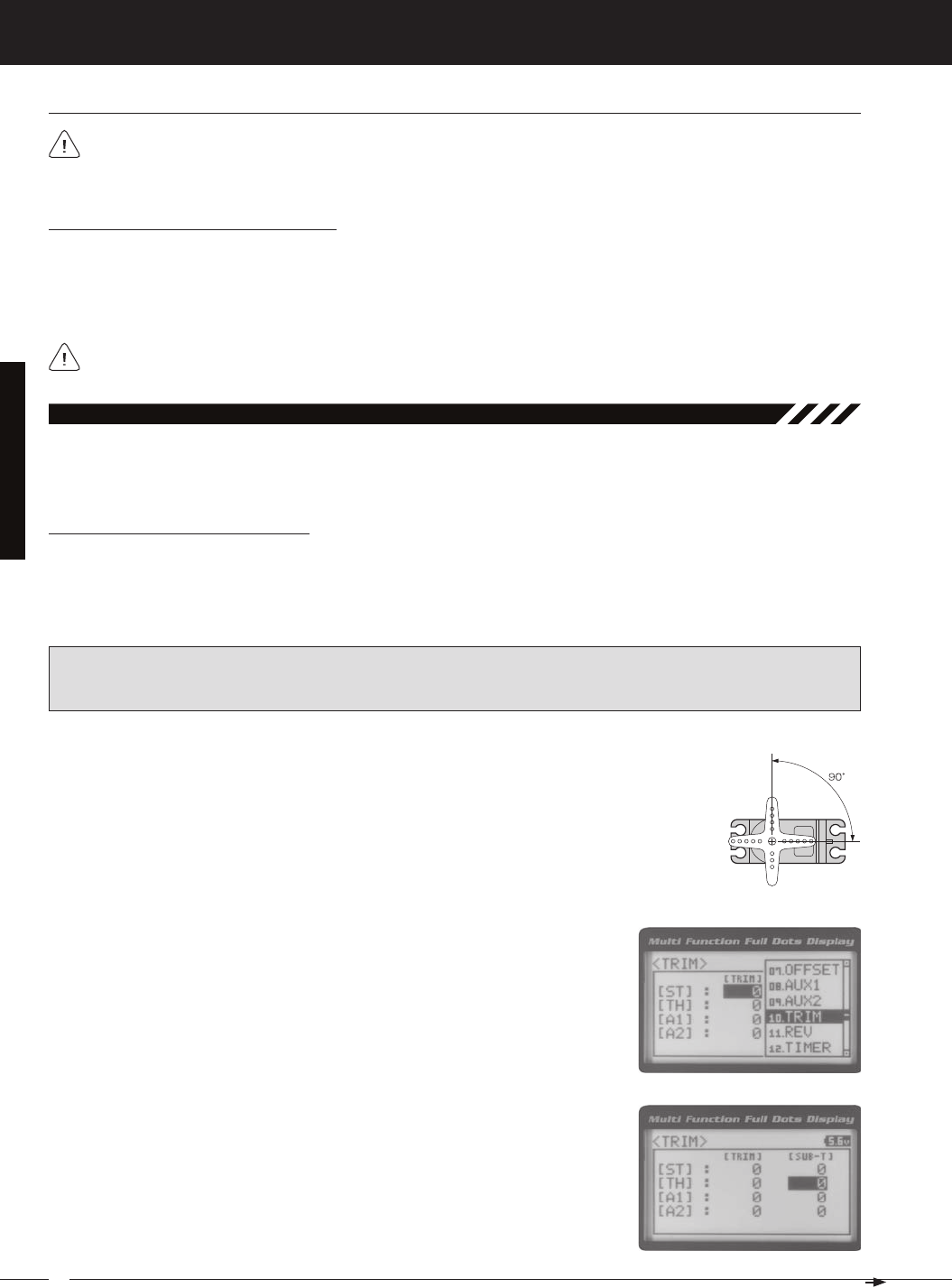
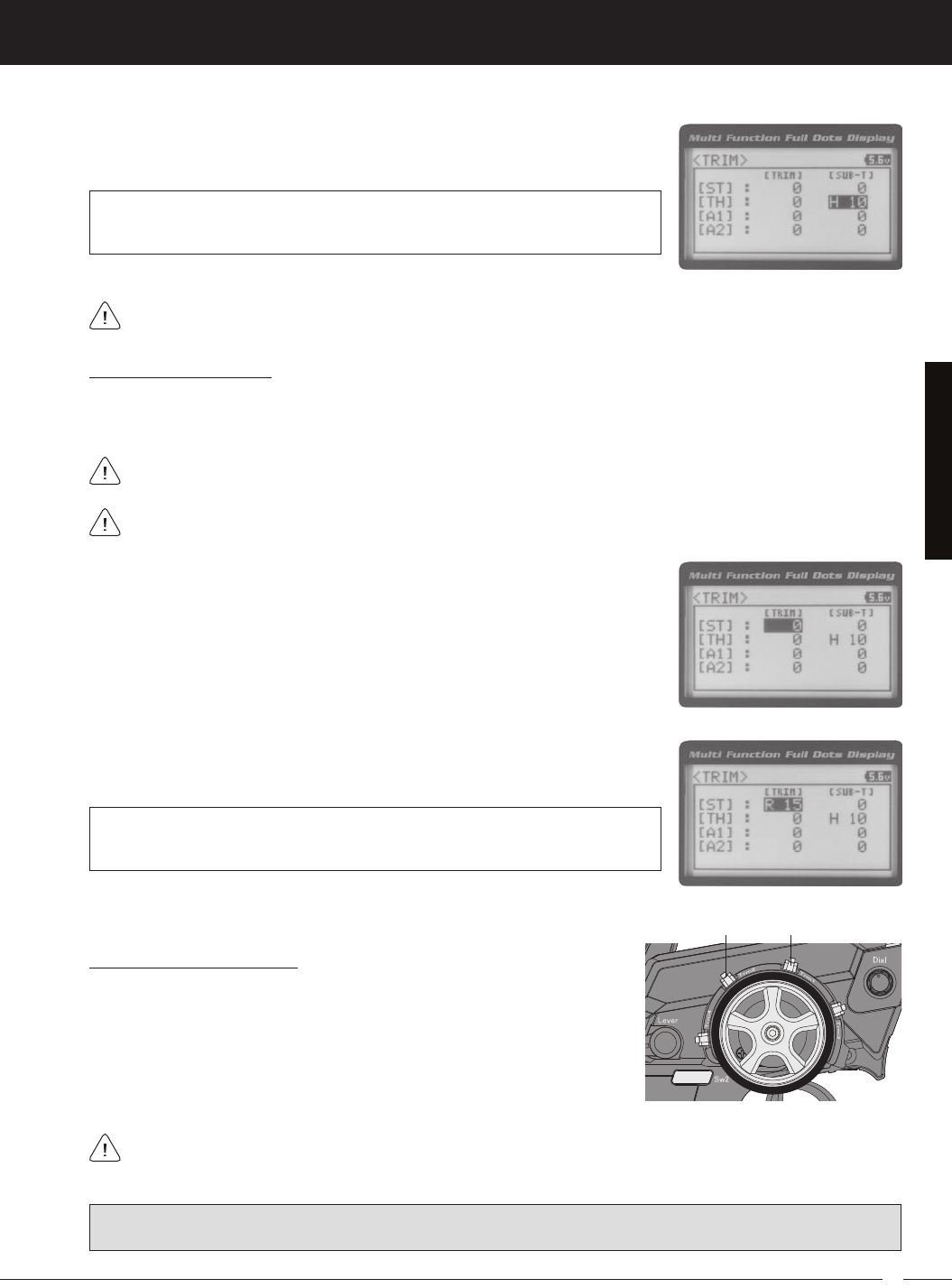
The Trim function allows you to view the currently programmed Trim value of each of the four channels and, if desired,
allows you to change the Trim values using the Push-Button Rotary Dial from within the Trim menu. In addition to the
10.triM (triM and Servo Sub-triM)
Adjusting the Servo Sub-Trim Values
It's not unusual that when you center a servo and install the servo horn, the servo horn is not perfectly centered as well.
The Servo Sub-Trim function allows you to correct the Neutral Trim setting for the Steering, Throttle, Auxiliary 1 and
Auxiliary 2 channels, making it possible to center the Trim Switches while ensuring the Steering, Throttle, Auxiliary 1 and
IMPORTANT: Before using the Servo Sub-Trim function, you should verify that all four Trim values are set to 0
(Centered). If they are not set to 0, adjust the Trim values to 0 using the Trim function. For more information, see the
Adjusting the Trim Values sections on the next page.
1) Install the servo horn (or servo saver for the Steering servo) onto your servo, making sure that
the servo horn (or servo saver) is as close to being centered as possible. In some cases, you
2) From the TOP screen, press the ENTER key to open the Programming Menu list.
3) Scroll UP or DOWN to highlight the TRIM menu, then press the ENTER key. The
4) Scroll UP or DOWN to highlight the desired channel you would like to change the
Sub-Trim value for. Choose from either [ST] : [SUB-T] 0 (Steering), [TH] : [SUB-T] 0
41
T R
MT-4S 2.4GHZ FH4T RADIO SYSTEM USER'S GUIDE
[[ProGraMMinG MenuS
Adjusting the Trim Values
The MT-4 2.4GHz FHSS-4T transmitter features Digital Trim Memory. Any amount of Trim that you set during use using
the Trim Switches is automatically stored in memory for that specific channel and for that specific model. The Trim values
2) Press the ENTER key, then scroll UP or DOWN to increase or decrease the Trim
TRIM TRIM setting range for the Steering channel is R100 to L100, for the Throttle
channel is H100 to B100 and for Auxiliary 1 Channel 3 and Auxiliary 2 Channel 4 is
H100 to L100. The default setting for all channels is 0.
Before adjusting the Trim values, you should first adjust the servo Sub-Trim values to center the servo horns. For
1) From within the TRIM menu, scroll UP or DOWN to highlight the desired channel
you would like to change the Trim value for. Choose from either [ST] : [TRIM] 0
5) Press the ENTER key, then scroll UP or DOWN to increase or decrease the Sub-
TRIM SUB-T setting range for the Steering channel is R150 to L150, for the Throttle
channel is H150 to B150 and for Auxiliary 1 Channel 3 and Auxiliary 2 Channel 4 is
H150 to L150. The default setting for all channels is 0.
After adjusting the Sub-Trim value, use the End Point Adjustment function to set the desired amount of maximum
Each time you move a Trim Switch a single audible tone is heard. When the Trim value reaches 0 (Centered), an
audible double-tone sounds. This indicates to you that the Trim is centered without the need to look down at the
Controlling the Trim Function
1) In the default configuration, Trim Switch Trm1 controls the Steering Right and
Left Trim and Trim Switch Trm2 controls the Throttle High and Brake Trim.
When you move the Trim Switches, the Trim percentage value changes in
5% increments. When you use the Trim function to change the Trim value,
the Trim value changes in 1% increments. Auxiliary 1 Trim and Auxiliary 2
Trim can be assigned to the remaining two Trim Switches, the Rotary Dial or
PRO TIP: The Trim function features two different Trim Type options that you can choose from. Choose from either
Center Trim or Parallel Trim. For more information, see the Trim Type section on pages 61 and 62.
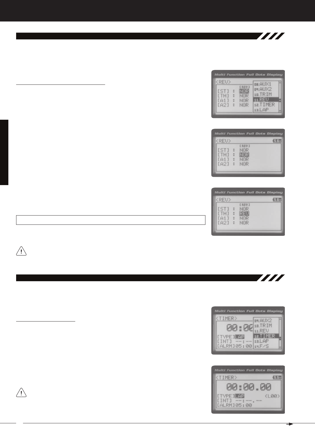
42
MT-4S 2.4GHZ FH4T RADIO SYSTEM USER'S GUIDE
T R
[[ProGraMMinG MenuS
The Servo Reversing function allows you to electronically switch the direction of servo travel. For example, if you rotate the
steering wheel to the right, and the steering servo moves to the left, you can use the Servo Reversing function to make
11.rev (Servo reverSinG)
Changing the Servo Reversing Values
1) From the TOP screen, press the ENTER key to open the Programming Menu list.
2) Scroll UP or DOWN to highlight the REV menu, then press the ENTER key. The
3) Scroll UP or DOWN to highlight the desired channel you would like to change the
Servo Reversing value for. Choose from either [ST] : NOR (Steering), [TH] : NOR
4) Press the ENTER key, then scroll UP or DOWN to change the direction of servo
REV setting range is NOR and REV. The default setting for all channels is NOR.
When you change the direction of servo travel, the servo horn may no longer be centered. If this occurs, use the
Servo Sub-Trim function to center the servo horn. For more information, see the Adjusting the Servo Sub-Trim Val-
The Track Timers function features three different Timers. Timers are provided for measuring Lap Times, Interval Times,
12.tiMer (traCk tiMerS)
Choosing the Timer Type
1) From the TOP screen, press the ENTER key to open the Programming Menu list.
2) Scroll UP or DOWN to highlight the TIMER menu, then press the ENTER key. The
3) Press the ENTER key, then scroll UP and DOWN to select the desired Timer Type.
To program the Lap Timer function, see the Lap Timer section on the next
page. To program the Interval Timer function, see the Interval Timer section
on page 46. To program the Countdown Timer function, see the Countdown
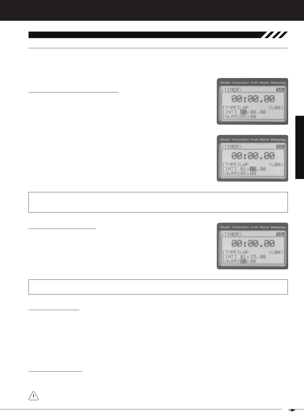
43
T R
MT-4S 2.4GHZ FH4T RADIO SYSTEM USER'S GUIDE
[[ProGraMMinG MenuS
[laP (laP tiMer)
The Lap Timer function allows you to measure and record times for up to 99 laps. The number of laps completed is dis-
played in the Timer menu, and when a lap is completed, the lap time is displayed momentarily on the TOP screen. An
Alarm (Goal Time) is featured that will sound when you reach your Goal Time and, if desired, the Interval Timer (Target
Setting the Interval Timer (Target Time)
1) From within the TIMER menu, scroll DOWN to highlight [INT] : --.
2) Press the ENTER key, then scroll UP or DOWN to set the desired Interval Timer
12.tiMer (traCk tiMerS), Continued....
TIMER INT setting range is -- : -- . -- to 99 : 59 : 99. The default setting is -- : -- . -- (OFF). When the Lap Timer is counting
up, an audible double-tone will sound each time the Lap Timer reaches the Interval Timer value. For example, if you
set the Interval Timer for 30 Seconds, an audible double-tone will sound every 30 seconds.
Setting the Alarm (Goal Time)
1) From within the TIMER menu, scroll DOWN to highlight [ALRM] 05.
2) Press the ENTER key, then scroll UP or DOWN to set the desired Alarm Minutes
value.
3) To set the Alarm Seconds value, press the ENTER key, then scroll DOWN to high-
TIMER ALRM setting range is 00:00 to 99:59. The default setting is 5:00 minutes. An audible tone will sound in 1 sec-
ond intervals 5 seconds before reaching the Goal Time. When the Goal Time is reached, a long audible tone will sound.
3) To set the Interval Timer Seconds value, press the ENTER key, then scroll DOWN
to highlight --. Press the ENTER key a second time, then scroll UP and DOWN to
set the desired Interval Timer Seconds value.
4) To set the Interval Timer 1/100th Seconds value, press the ENTER key, then scroll
DOWN to highlight --. Press the ENTER key a second time, then scroll UP and
Starting the Lap Timer
1) In the default configuration, Push-Button Switch Sw2 controls the Lap Timer. Press and HOLD the Push-Button Switch
for 3 seconds. An audible double-tone will sound and LAP will flash on the TOP screen indicating the Lap Timer is in
Stand-by. To start the Lap Timer, press the Push-Button Switch a second time or pull the Throttle Trigger. An audible
double-tone will sound and the Lap Timer will start counting up. Pressing the Push-Button Switch a second time will
store the first Lap Time, then begin counting a second Lap Time. Each time you press the Push-Button Switch, an
audible tone sounds, the previous Lap Time is stored, a new Lap Time begins and the current Lap Time is displayed
momentarily on the TOP screen. If desired, the Timer Function can be assigned to Push-Button Switch Sw1. For more
Stopping the Lap Timer
1) To stop the Lap Timer, press and HOLD the Push-Button Switch for 3 seconds. An audible double-tone will sound
The Cumulative Time cannot be manually cleared. It will be automatically cleared when the Lap Timer is put in
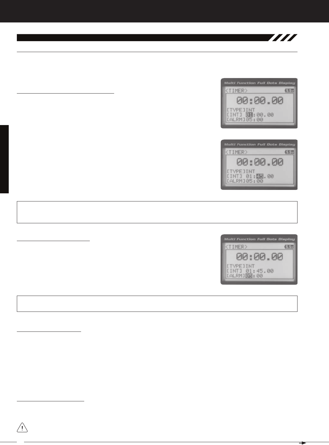
44
MT-4S 2.4GHZ FH4T RADIO SYSTEM USER'S GUIDE
T R
[[ProGraMMinG MenuS
int (interval tiMer)
The Interval Timer (Target Time) function notifies you when a set interval elapses while you are driving, giving you an
12.tiMer (traCk tiMerS), Continued....
Setting the Interval Timer (Target Time)
1) From within the TIMER menu, scroll DOWN to highlight [INT] : --.
2) Press the ENTER key, then scroll UP or DOWN to set the desired Interval Timer
TIMER INT setting range is -- : -- . -- to 99 : 59 : 99. The default setting is -- : -- . -- (OFF). When the Interval Timer is started,
an audible double-tone will sound each time the Interval Timer reaches the Interval Timer value. For example, if you
set the Interval Timer for 1 Minute, an audible double-tone will sound every Minute.
3) To set the Interval Timer Seconds value, press the ENTER key, then scroll DOWN
to highlight --. Press the ENTER key a second time, then scroll UP and DOWN to
set the desired Interval Timer Seconds value.
4) To set the Interval Timer 1/100th Seconds value, press the ENTER key, then scroll
DOWN to highlight --. Press the ENTER key a second time, then scroll UP and
Setting the Alarm (Goal Time)
1) From within the TIMER menu, scroll DOWN to highlight [ALRM] 05.
2) Press the ENTER key, then scroll UP or DOWN to set the desired Alarm Minutes
value.
3) To set the Alarm Seconds value, press the ENTER key, then scroll DOWN to high-
TIMER ALRM setting range is 00:00 to 99:59. The default setting is 5:00 minutes. An audible tone will sound in 1 sec-
ond intervals 5 seconds before reaching the Goal Time. When the Goal Time is reached, a long audible tone will sound.
Starting the Interval Timer
1) In the default configuration, Push-Button Switch Sw2 controls the Interval Timer. Press and HOLD the Push-Button
Switch for 3 seconds. An audible double-tone will sound and INT will flash on the TOP screen indicating the Interval
Timer is in Stand-by. To start the Interval Timer, press the Push-Button Switch a second time or pull the Throttle Trig-
ger. An audible double-tone will sound and the Interval Timer will start counting up. Each time the programmed Interval
Time elapses, an audible double-tone will sound and the Interval Timer will restart from zero and the Cumulative
Time will be displayed on the TOP screen. You can manually restart the Interval Timer from zero by pressing the
Push-Button Switch while the Interval Timer is running. If desired, the Timer Function can be assigned to Push-Button
Stopping the Interval Timer
1) To stop the Interval Timer, press and HOLD the Push-Button Switch for 3 seconds. An audible double-tone will sound in-
The Cumulative Time cannot be manually cleared. It will be automatically cleared when the Interval Timer is put
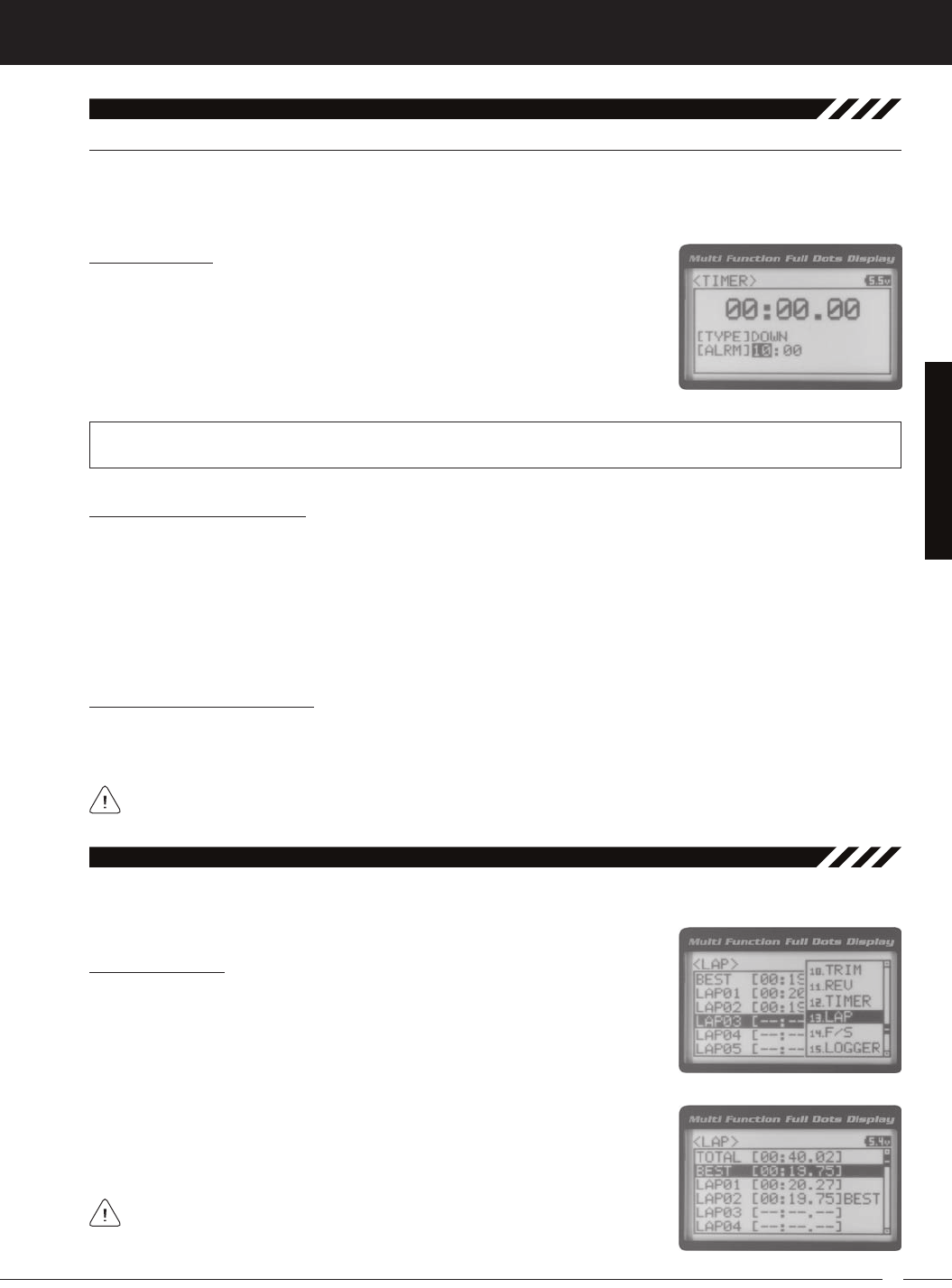
45
T R
MT-4S 2.4GHZ FH4T RADIO SYSTEM USER'S GUIDE
[[ProGraMMinG MenuS
down (Countdown tiMer)
The Countdown Timer function can be used to notify you of your model’s running time. For example, you can set the
Countdown Timer to alert you when it's time to refuel. When the Countdown Timer expires, a long audible tone will
12.tiMer (traCk tiMerS), Continued....
Setting the Alarm
1) From within the TIMER menu, scroll DOWN to highlight [ALRM] 05.
2) Press the ENTER key, then scroll UP or DOWN to set the desired Alarm Minutes
value.
3) To set the Alarm Seconds value, press the ENTER key, then scroll DOWN to high-
TIMER ALRM setting range is 00:00 to 99:59. The default setting is 5:00 minutes. An audible tone will sound in 1 second inter-
vals 5 seconds before reaching the Countdown Alarm Time. When the Countdown Alarm Time is reached, a long audible
Starting the Countdown Timer
1) In the default configuration, Push-Button Switch Sw2 controls the Countdown Timer. Press and HOLD the Push-
Button Switch for 3 seconds. An audible double-tone will sound and DWN will flash on the TOP screen indicating the
Countdown Timer is in Stand-by. To start the Countdown Timer, press the Push-Button Switch a second time or pull
the Throttle Trigger. An audible double-tone will sound and the Countdown Timer will start counting down. An audible
tone will sound in 1 second intervals 5 seconds before reaching zero. When zero is reached, a long audible tone will
sound and the Countdown Timer will begin counting Up. You can manually stop the Countdown Timer at any time by
pressing the Push-Button Switch. Press the Push-Button Switch again will start the Countdown Timer from where it
Stopping the Countdown Timer
1) To stop the Countdown Timer, press and HOLD the Push-Button Switch for 3 seconds. An audible double-tone will
sound indicating the Countdown Timer is stopped and either the remaining Countdown Time or elapsed Count Up
The remaining Countdown Time or Count Up Time cannot be manually cleared. It will be automatically cleared
The Lap Times menu displays a total of up to 99 laps that are recorded using the Lap Timer function. Each Lap Time is
13.laP (laP tiMeS)
Viewing Lap Times
1) From the TOP screen, press the ENTER key to open the Programming Menu list.
2) Scroll UP or DOWN to highlight the LAP menu, then press the ENTER key. The LAP
3) Scroll UP and DOWN to view the stored Lap Times. Lap Times are stored from
the time you start the Lap Timer to the time you Stop the Lap Timer. The Total
Lap Times are stored until you restart the Lap Timer function. When the Lap
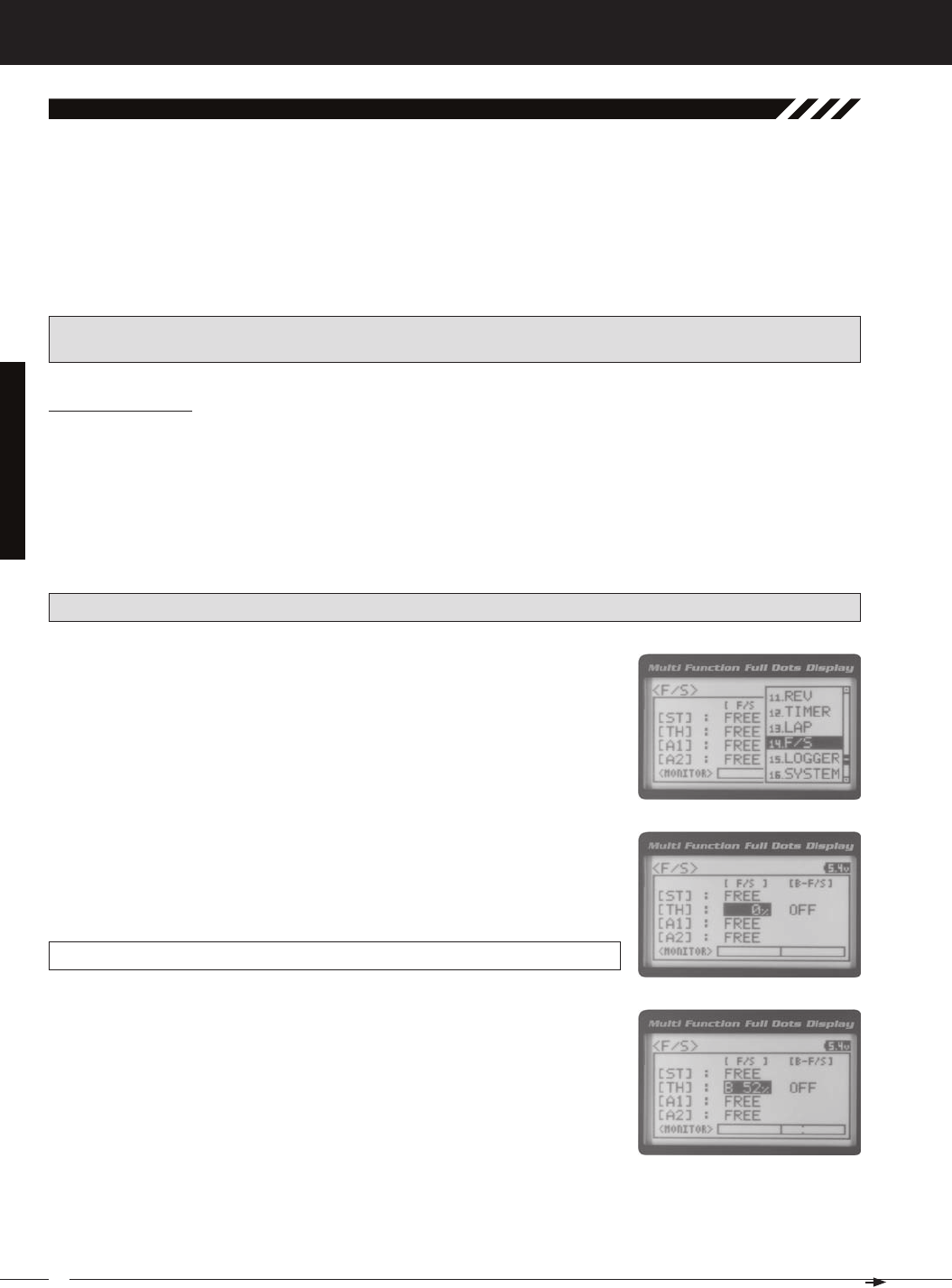
46
MT-4S 2.4GHZ FH4T RADIO SYSTEM USER'S GUIDE
T R
The Fail Safe function automatically moves the servos to a predetermined position in the event that the signal between
the transmitter and the receiver is interrupted, whether due to signal degradation or to low transmitter battery. Several
different setting options are available. The Fail Safe function can be set to Hold the servos in the last position they were
in when the signal was lost, or each of the servos can be set to move to a custom position when the signal is lost. For
example, the throttle servo moves to the Brake Side to engage the brakes and stop your model. If you're driving a gas- or
glow-powered boat, the Fail Safe function could be set to lower the throttle to idle and turn the rudder slightly left or right
so that the boat will continue in slow circles.
In addition, a Receiver Battery Voltage Fail Safe function is available which allows you to set a custom voltage that the
14.f/S (fail Safe)
[[ProGraMMinG MenuS
Setting the Fail Safe
Fail Safe settings can be programmed for each of the four channels individually. In addition, Fail Safe settings are Model-
specific, meaning you can have different Fail Safe settings for each Model in memory. The Fail Safe settings will be re-
tained even if the transmitter loses power or if the transmitter and receiver must be paired again. Three Fail Safe options
are available for each channel as described below:
FREE - Fail Safe is disabled for this channel. Servos can move freely when the signal is lost.
HOLD - When Fail Safe Activates, the servo will be held in the last position it was in when the signal was lost.
IMPORTANT: The Fail Safe function will NOT OPERATE if the receiver loses power. It will operate only if the transmit-
ter and receiver signal is interrupted or if the transmitter loses power.
1) From the TOP screen, press the ENTER key to open the Programming Menu list.
2) Scroll UP or DOWN to highlight the F/S menu, then press the ENTER key. The F/S
5) To program a Fail Safe percentage value, move the control the amount you want
the servo to move to when the Fail Safe function Activates and HOLD it in that
position, then press and HOLD the ENTER key until an audible tone sounds. The
percentage and direction the servo will travel will be displayed. For example, to
set the Throttle Brake to engage when the Fail Safe function Activates, push the
throttle trigger toward the Brake side the desired amount, HOLD the throttle trig-
ger in that position, then press and HOLD the ENTER key. The percentage value
3) Scroll UP or DOWN to highlight the desired channel you would like to change the
Fail Safe option for.
4) Press the ENTER key, then scroll UP or DOWN to choose the desired Fail Safe
F/S setting range is FREE, HOLD, or %. The default setting is FREE.
PRO TIP: Use the Servo Monitor at the bottom of the F/S menu to see your programming changes in virtual real time.
6) Check to ensure your Fail Safe settings are working properly prior to running your model. For safety, it's preferable to
have someone hold your model. To check the Fail Safe settings, make sure that both the transmitter and receiver are
turned ON, then, while someone is holding your model, turn the transmitter OFF. The servos should react correctly
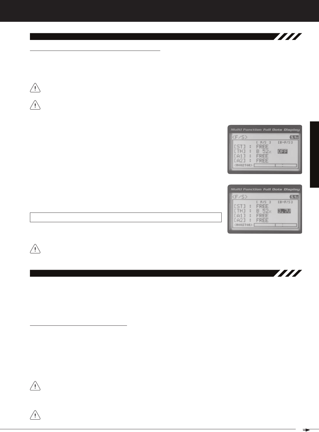
47
T R
MT-4S 2.4GHZ FH4T RADIO SYSTEM USER'S GUIDE
[[ProGraMMinG MenuS
14.f/S (fail Safe), Continued....
Setting the Receiver Battery Voltage Fail Safe Function
The Receiver Battery Voltage Fail Safe function allows you to set a custom voltage that the Receiver Battery Voltage Fail
Safe function will Activate at. When your receiver battery voltage drops to the programmed voltage, the throttle servo will
move to the predetermined position you programmed in step 5 in the Setting the Fail Safe section on the previous page. If
If FREE or HOLD is chosen for the Throttle channel, you cannot Activate the Receiver Battery Voltage Fail Safe
The Receiver Battery Voltage Fail Safe function works only with FHSS-4T and FHSS-3 receivers. When using an
FHSS-2 receiver, these Fail Safe features are not supported. In this case, Fail Safe must be programmed through
1) Follow steps 1 through 5 in the Setting the Fail Safe section on the previous page
to program a Throttle Fail Safe percentage value.
2) From within the F/S menu, press the ENTER key, then scroll DOWN to highlight
3) Press the ENTER key, then scroll UP or DOWN to choose the desired Receiver
F/S B-F/S setting range is 3.5v to 7.4v. The default setting is OFF.
The receiver will operate down to 2.5 volts, however, the minimum operating voltage of most servos is higher than
that. The Receiver Battery Fail Safe Voltage should be set to a value that will allow all of your servos to operate.
The Telemetry Log function allows you to view a log of the Telemetry Data that is sent from the receiver to the transmit-
ter. You are able to view Telemetry Data for both Temperature outputs, the RPM output and the receiver's Voltage. This
information can be used to track specific information about your model, such as cylinder head temperature if you're
running a nitro-powered model. The interval that Telemetry Data is read and stored can be adjusted so that Telemetry
15.loGGer (teleMetry loG)
Starting and Stopping the Telemetry Log
The Telemetry Log function must be Started in order for the transmitter to read and store Telemetry Data from the re-
ceiver.
1) In the default configuration, Push-Button Switch Sw1 controls the Telemetry Log. To start the Telemetry Log, press
the Push-Button switch. LED1 (Blue) will flash, indicating the Telemetry Log is storing data. Telemetry Data is stored
for all four Telemetry functions, whether the Telemetry Sensors are hooked up or not.
Each time the Telemetry Log is started, any old Telemetry Data is automatically erased. In addition, the Telemetry
Log will stop automatically once the Telemetry Log is filled. The Telemetry Log can store 120 separate entries. If the
Log Interval is set to 00.1 seconds, the Telemetry Log can record for 12 seconds. If the Log Interval is set to 45.1 seconds,
If a Telemetry Sensor is not connected, default Telemetry Data for that input will be shown in the Telemetry Log.
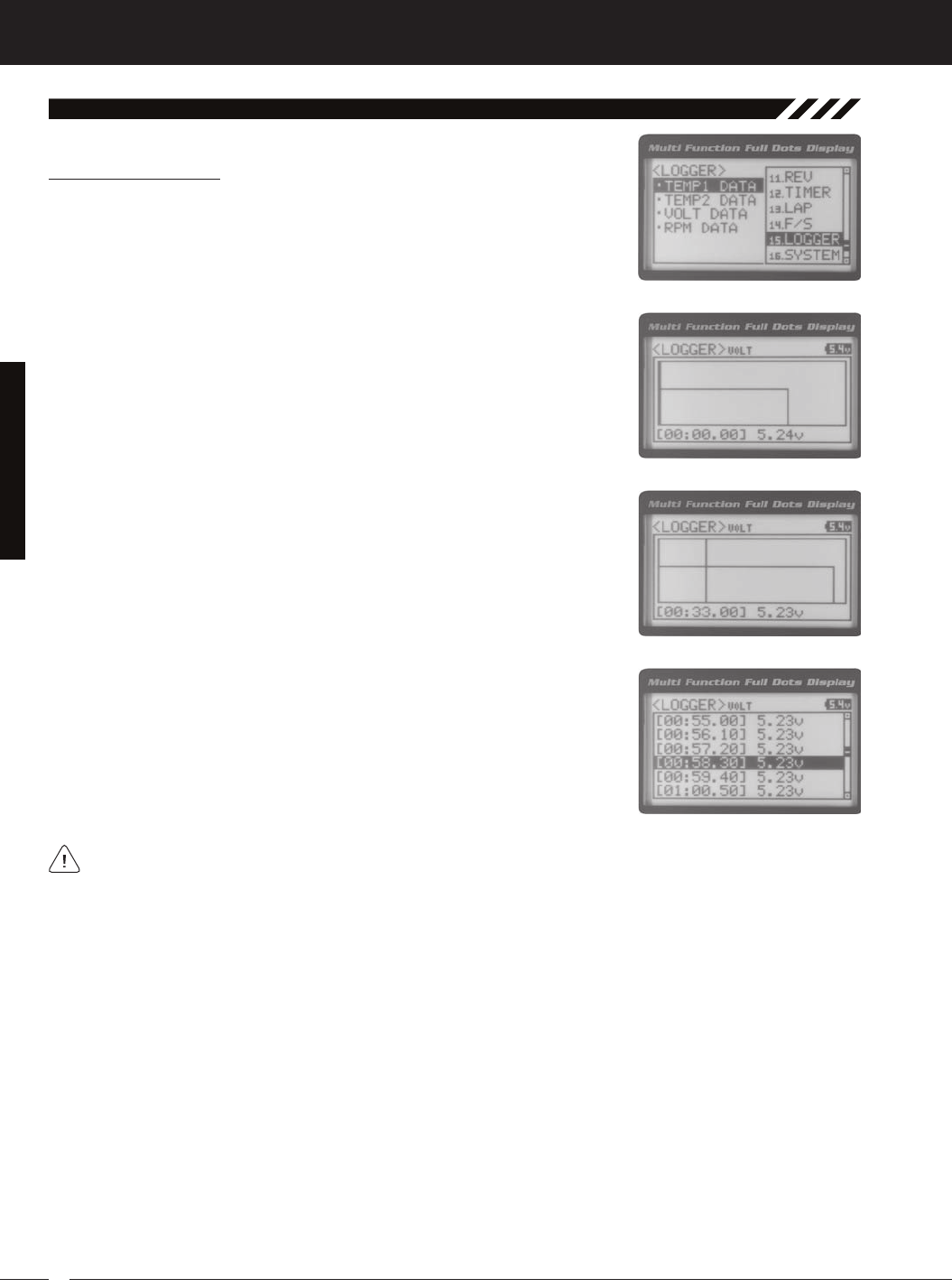
48
MT-4S 2.4GHZ FH4T RADIO SYSTEM USER'S GUIDE
T R
[[ProGraMMinG MenuS
15.loGGer (teleMetry loG), Continued....
Viewing Telemetry Data
1) From the TOP screen, press the ENTER key to open the Programming Menu list.
2) Scroll UP or DOWN to highlight the LOGGER menu, then press the ENTER key.
3) From within the LOGGER menu, scroll UP or DOWN to highlight the desired Te-
lemetry Data you would like to view. Choose from TEMP1 DATA, TEMP2 DATA,
VOLT DATA or RPM DATA.
5) Telemetry Data can be viewed a couple of different ways. To view the Telemetry
Data at a specific point along the graph, scroll UP or DOWN to move the vertical
line right or left. The Telemetry Data for each point the vertical line is at is dis-
6) To view all of the Telemetry Data points, press the ENTER key to open the Te-
The Telemetry Log can be started and stopped while viewing Telemetry Data. To start the Telemetry Log, press and
THIS SPACE INTENTIONALLY LEFT BLANK
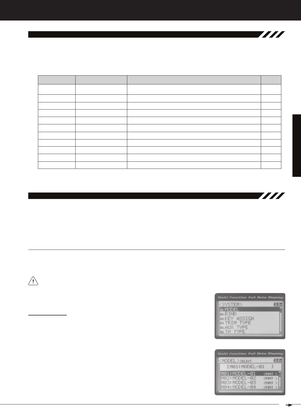
49
T R
MT-4S 2.4GHZ FH4T RADIO SYSTEM USER'S GUIDE
SySteM MenuS
01.Model (Model SeleCt, naMinG, CoPy and Clear)
The Model menu allows you to select different models using the Model Select function, name your saved models, using
the Model Naming function, and copy Programming Data from one model to another, or clear Programming Data from
one or more models using the Model Copy and Model Clear functions. Programming Data for up to 18 different models
can be stored in the transmitter's memory. This allows you to use the transmitter with different models and quickly and
easily select the Programming Data for each of them. In addition, a Model Select Shortcut function is also featured for
To access the various System Menus, turn the transmitter ON, then press the ENTER key (Push-Button Rotary Dial) to
open the Programming Menu list. Scroll DOWN to SYSTEM, then press the ENTER key a second time to open the System
Menu. A list of System Menus will be displayed and the first System Menu will be highlighted.
overview
01.MODEL
02.BIND
03.KEY ASSIGN
04.TRIM TYPE
05.AUX TYPE
06.TH TYPE
07.BUZZER
08.BATTERY
09.LCD
10.TELEMETRY
Model
Binding
Key Assignments
Servo Trim Type
Auxiliary Type
Throttle Type
Audible Key Tone
Voltage Alarm
Contrast
Telemetry
Model Select, Model Naming, Model Copy and Model Clear
Bind the Transmitter and Receiver, Select Modulation Type and Servo Mode
Assign Functions to the Switches Rotary Dial and Auxiliary Lever
Change the Servo Trim Type
Choose the Auxiliary 1 and Auxiliary 2 Programming Functions
Change the Throttle Servo Travel Proportion
Turn Audible Key Tones ON or OFF and Control Their Pitch and Volume
Specify the Low Voltage and Limit Alarms for the Transmitter Battery
Adjust the Contrast of the Multi-Function LCD Screen
Program Telemetry Screen and Telemetry Log Options
PG. 51
PG. 54
PG. 56
PG. 61
PG. 62
PG. 63
PG. 63
PG. 64
PG. 65
PG. 66
Model SeleCt (Model SeleCt)
The Model Select function allows you to load the Programming Data for the particular model you wish to drive. The Model
Select menu displays the currently selected model, along with a list of available models that can be selected. The Modu-
Selecting a Model
2) Press the ENTER key to open the MODEL menu. MODEL SELECT will be high-
lighted.
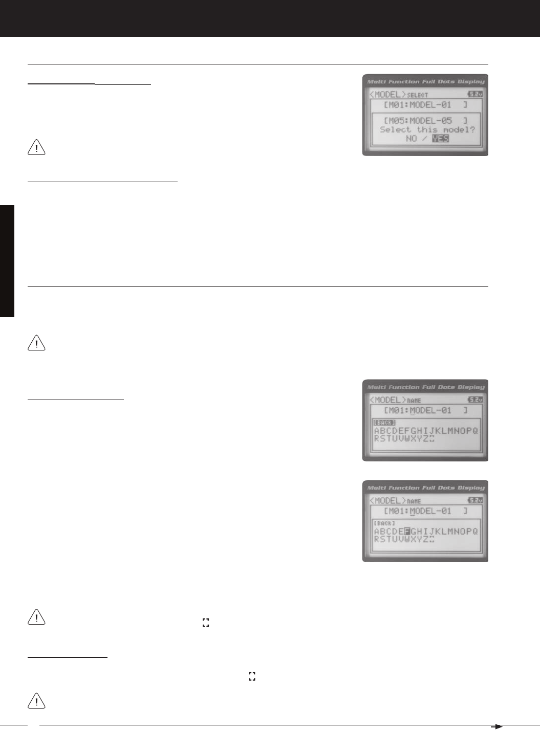
50
MT-4S 2.4GHZ FH4T RADIO SYSTEM USER'S GUIDE
T R
When a model is selected, the Programming Data for that model will be load-
Selecting a Model, Continued....
4) Scroll UP or DOWN to highlight the model you would like to select, then press
the ENTER key. Select this model? NO/YES will be displayed. Scroll DOWN to
highlight YES, then press the ENTER key. The model that you just selected will be
Model SeleCt (Model SeleCt), Continued....
Model Select Shortcut (Direct Model)
The Model Select Shortcut function allows you to jump directly to the DIRECT MODEL menu when you turn the transmit-
1) Turn the transmitter OFF.
2) Press and HOLD the Back/Cancel key, then turn the transmitter ON. The DIRECT MODEL menu will be displayed. To
SySteM MenuS
Deleting a Character
1) Scroll UP or DOWN to move the underscore under the character in your Model Name you want to delete. Press the
Model naMe (Model naMinG)
The Model Naming function allows you to name each of the 18 individual models. This makes it easy to keep track
of multiple models. The Model Name can consist of up to 10 letters, numbers, or symbols. Choose from capital letters,
Entering a Model Name
1) From within the MODEL menu, scroll DOWN to highlight MODEL NAME.
2) Press the ENTER key. The MODEL NAME menu will be displayed, [BACK] will be
highlighted and the underscore will be flashing under the first editable character
A model must be selected before a Model Name can be entered or modified. In the default configuration,
M01:MODEL-1 is selected. To enter a Model Name for another model, that model must first be selected using the
3) Scroll UP or DOWN to move the underscore to the character you would like
change.
4) Press the ENTER key, then scroll UP or DOWN to highlight a character in the Char-
acter List. Press the ENTER key a second time to select the highlighted character.
5) Repeat steps 3 and 4 to enter the rest of the characters. Up to ten characters can be entered. Press the Back/Cancel
To select lower case letters, numbers or symbols, continue to scroll UP or DOWN through the various Character
If you can't move the underscore, press the Back/Cancel key to re-gain control of the underscore (the underscore
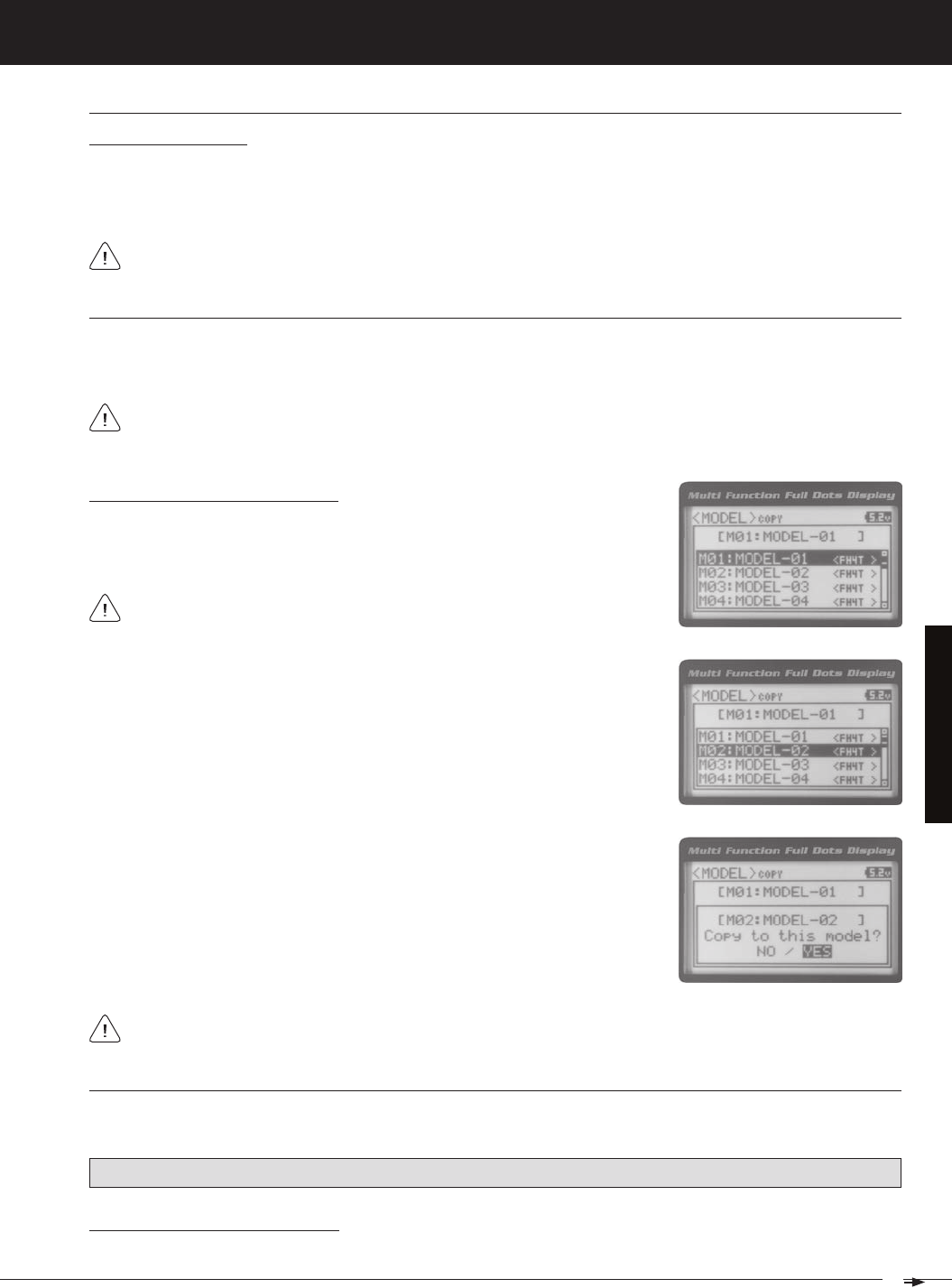
51
T R
MT-4S 2.4GHZ FH4T RADIO SYSTEM USER'S GUIDE
SySteM MenuS
Deleting a Model Name
1) Scroll DOWN to move the underscore under the last character in your Model Name.
2) Press the ENTER key. Scroll UP or DOWN to highlight [BACK], then continuously press the ENTER key to delete each
Model naMe (Model naMinG), Continued....
Model CoPy (Model ProGraMMinG data CoPy)
The Model Copy function allows you to copy the Programming Data from one model to another model. For example, if
you have two models that are similar, you can copy the Programming Data from the first model to the second model to
3) Scroll UP or DOWN to highlight the model you would like to copy the Program-
Copying Model Programming Data
1) From within the MODEL menu, scroll DOWN to highlight MODEL COPY.
2) Press the ENTER key. The MODEL COPY menu will be displayed and the first
The Model Copy function allows you to copy Programming Data FROM the currently selected model TO any other
model in the Model Copy List. Make sure that prior to using the Model Copy function, you first select and load the
4) Press the ENTER key. Copy to this model? NO/YES will be displayed. Scroll
DOWN to highlight YES, then press the ENTER key. After ~3 seconds, Executed
All model-specific Programming Data, including the Model Name will be copied to the highlighted model. If you
Model Clear (Model ProGraMMinG data reSet)
The Model Clear function allows you to Reset model-specific Programming Data for any model back to the factory
Clearing Model Programming Data
WARNING: When the Model Clear function is Executed, all custom Programming Data for that model will be lost!
If you can't move the underscore, press the Back/Cancel key to re-gain control of the underscore (the underscore
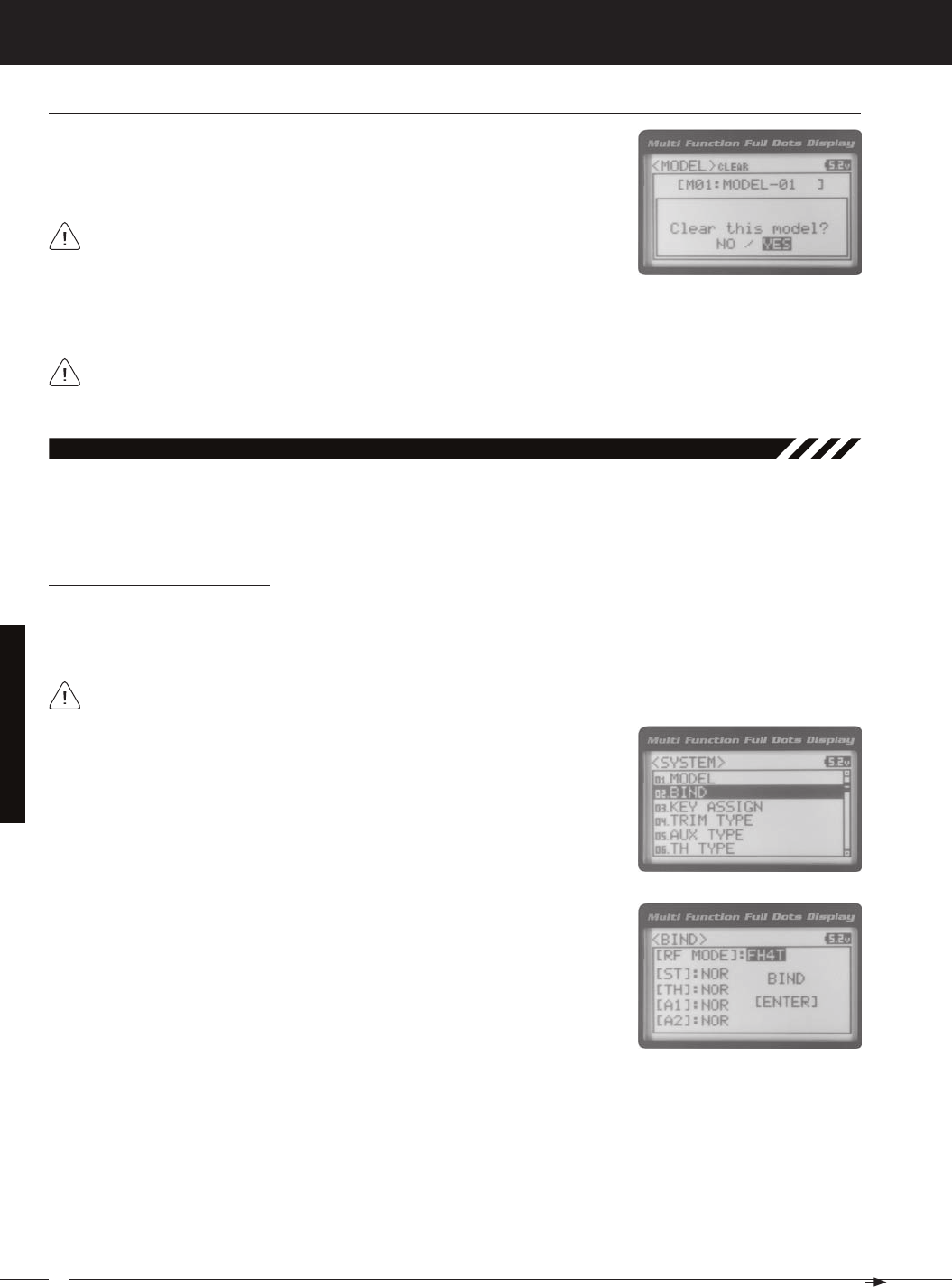
52
MT-4S 2.4GHZ FH4T RADIO SYSTEM USER'S GUIDE
T R
SySteM MenuS
4) Scroll DOWN to highlight YES, then press the ENTER key. After ~3 seconds, Executed will flash, indicating the Program-
All model-specific Programming Data, including the Model Name and Modulation Type will be Reset to the default
values. In addition, if you want to go back and change models or you don't want to Reset the Programming Data
Model Clear (Model ProGraMMinG data reSet), Continued....
2) From within the MODEL menu, scroll DOWN to highlight MODEL CLEAR.
02.bindinG (bindinG, Modulation tyPe and Servo Mode)
The Binding function allows you to 'Bind' the transmitter and receiver pair. When new, it is necessary to pair the transmit-
ter and receiver to prevent interference from transmitters operated by other users. This operation is referred to as 'Bind-
ing'. Once the Binding process is complete, the setting is remembered even when the transmitter and receiver are turned
Changing the Modulation Type
The Modulation Type function allows you to choose the transmitter Modulation Type. The Modulation Type can be
changed to match the receiver you're using. For example, if you wish to use an Airtronics 2.4GHz FHSS-2 receiver with
your transmitter, you would need to change the Modulation Type to FH2 prior to Binding your transmitter and receiver.
The following Modulation Type options are available:
FH2 - Select this Modulation Type when using Airtronics 2.4GHz FHSS-2 surface receivers.
FH3 - Select this Modulation Type when using Airtronics 2.4GHz FHSS-3 receivers.
FH3F - This Modulation Type is NOT used in North America. This Modulation Type is typically used in France.
FH4T - Select this Modulation Type when using Airtronics 2.4GHz FHSS-4T Telemetry receivers.
2) Press the ENTER key. The BIND menu will be displayed and [RF MODE] : FH4T
will be highlighted.
3) Press the ENTER key, then scroll UP or DOWN to select the desired Modulation
Type.
The Modulation Type must be chosen prior to Binding the transmitter and receiver. Make sure the Modulation Type
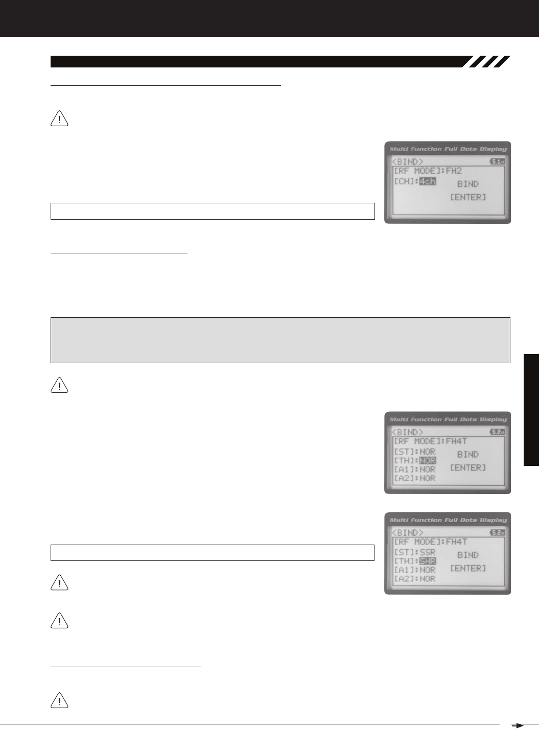
53
T R
MT-4S 2.4GHZ FH4T RADIO SYSTEM USER'S GUIDE
SySteM MenuS
02.bindinG (bindinG, Modulation tyPe and Servo Mode), Continued....
Changing the Channel Mode - FH2 Modulation Type Only
1) From within the BIND menu, scroll DOWN to highlight [CH] : 4ch.
2) Press the ENTER key, then scroll UP or DOWN to choose the desired Channel
Mode. Selecting 2CH will enable 2-channel operation (Steering and Throttle). Se-
BIND CH setting range is 2CH and 4CH. The default setting is 4CH.
Changing the Servo Mode Setting
The Servo Mode setting can be changed to suit the type of servos you're using in your model. For example, using the SHR
setting with Digital servos will increase the servo's response time, even above the manufacturer's stated specification. If
you're using Airtronics SRG Digital servos, you can use the SSR setting for the fastest response time. The combination of
using Digital servos and using the correct Servo Mode setting results in the ultimate feel and response, making you feel
SHR and SSR Servo Modes should only be used with Digital servos. While the SHR Servo Mode can be used with
WARNING: If you're using Analog servos in your model, DO NOT use SHR or SSR Servo Mode options for that channel.
Use the NOR (Normal) Servo Mode with Analog servos. Using SHR or SSR Servo Mode options with Analog servos can
result in poor performance or even damage to the servos or the receiver! In addition, not all ESCs are compatible with
SHR or SSR Servo Modes. If your ESC does not operate correctly, change the Throttle Channel Servo Mode setting to
1) From within the BIND menu, scroll UP or DOWN to highlight the desired channel
you would like to change the Servo Mode option for. Choose from either [ST] :
2) Press the ENTER key, then scroll UP or DOWN to choose the desired Servo
SERVO MODE setting range is NOR, SHR and SSR. The default setting is NOR.
Binding the Transmitter and Receiver
We recommend that you choose your desired Servo Mode options prior to Binding the transmitter and receiver.
Servo Mode option changes will not take effect immediately. If you change the Servo Mode after Binding the trans-
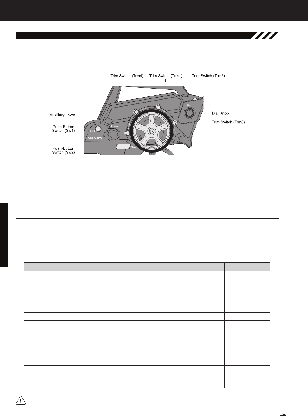
54
MT-4S 2.4GHZ FH4T RADIO SYSTEM USER'S GUIDE
T R
SySteM MenuS
SwitCH (PuSH-button SwitCH key aSSiGnMentS)
The Key Assignments function allows you to assign the ON/OFF control of various functions to Push-Button Switches
Sw1 and Sw2. This allows you to use the Push-Button Switches to turn functions OFF and ON during use. One function
can be assigned to each Push-Button switch, although both Push-Button Switches can be OFF or ON at the same time.
Trm1 - Steering Trim
Trm2 - Throttle Trim
Trm3 - Steering Dual Rate Sw1 - Telemetry Logger ON/
OFF
Dial Knob - Auxiliary 1 Channel 3
03.key aSSiGn (key aSSiGnMentS)
The Key Assignments function allows you to assign different functions to each of the two Push-Button Switches, the
four Trim Switches, the Dial Knob and the Auxiliary Lever. In addition, the ON/OFF behavior of some Push-Button Switch
functions can be changed. The Key Assignments function also allows you to change the Direction of Travel and the Trim
Resolution of the four Trim Switches and the Rotary Dial. This allows you to fine-tune the movement of the servos when
OFF
D/R-ST
D/R-TH
D/R-BR
CUR-ST
CUR-TH
SPD-ST
SPD-TH
ALB
OFFSET
AUX1
AUX2
TIMER
TE-CLR
Inhibited
Dual Rate-Steering
Dual Rate-Throttle
Dual Rate-Brake
Curve-Steering
Curve-Steering
Servo Speed-Steering
Servo Speed-Throttle
Anti-Lock Braking
Throttle Offset
Auxiliary 1 Channel 3
Auxiliary 2 Channel 4
Lap, Interval and Countdown Timers
Telemetry Clear
Sw2
------
Toggle
Toggle
Toggle
Toggle
Toggle
Toggle
Toggle
Toggle
Toggle
Toggle
Toggle
------
------
------
ON
ON
ON
ON
ON
ON
ON
ON
ON
ON
ON
OFF
OFF
When you program a function, that function is ON (Active) by default, unless the function's default ON/OFF value is
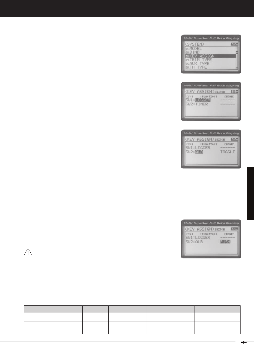
55
T R
MT-4S 2.4GHZ FH4T RADIO SYSTEM USER'S GUIDE
SySteM MenuS
Changing the Push-Button Switch Function
1) From within the SYSTEM menu, scroll UP or DOWN to highlight the KEY ASSIGN
2) Press the ENTER key to open the KEY ASSIGN menu. SWITCH will be highlighted.
3) Press the ENTER key. The SWITCH menu will be displayed and SW1 : LOGGER
4) Scroll UP or DOWN to highlight the function you would like to change for either
SW1 or SW2.
5) Press the ENTER key, then scroll UP or DOWN to choose the desired function for
either SW1 or SW2. A list of functions that can be assigned to the Push-Button
SwitCH (PuSH-button SwitCH key aSSiGnMentS), Continued....
Changing the Switch Mode
Some functions allow you to change how the Push-Button Switch operates. The following Switch Modes are available:
TOGGLE - When selected, press the Push-Button Switch to turn the function ON and press the Push-Button Switch
a second time to turn the function OFF. See note at the bottom of the previous page.
PUSH - When selected, press and HOLD the Push-Button Switch to turn the function ON. When the Push-Button
1) From within the KEY ASSIGN SWITCH menu, scroll DOWN to highlight the MODE
you would like to change for either SW1 or SW2.
2) Press the ENTER key, then scroll UP or DOWN to choose the desired Switch
The Switch Mode cannot be changed for all functions. When [MODE] ------,
triM, dial and lever (triM, dial and lever key aSSiGnMentS)
The Key Assignments function allows you to assign different functions to Trim Switches Trm1, Trm2, Trm3 and Trm4, the
Rotary Dial and the Auxiliary Lever. This allows you to use the Trim Switches, Rotary Dial and Auxiliary Lever to control
those functions while you're driving. In addition, the Direction of Travel (REV) and the Trim Resolution (Step value) of
OFF
TRIM-ST
Inhibited
T r i m - S t e e r i n g Trm1
------
5
------
NOR
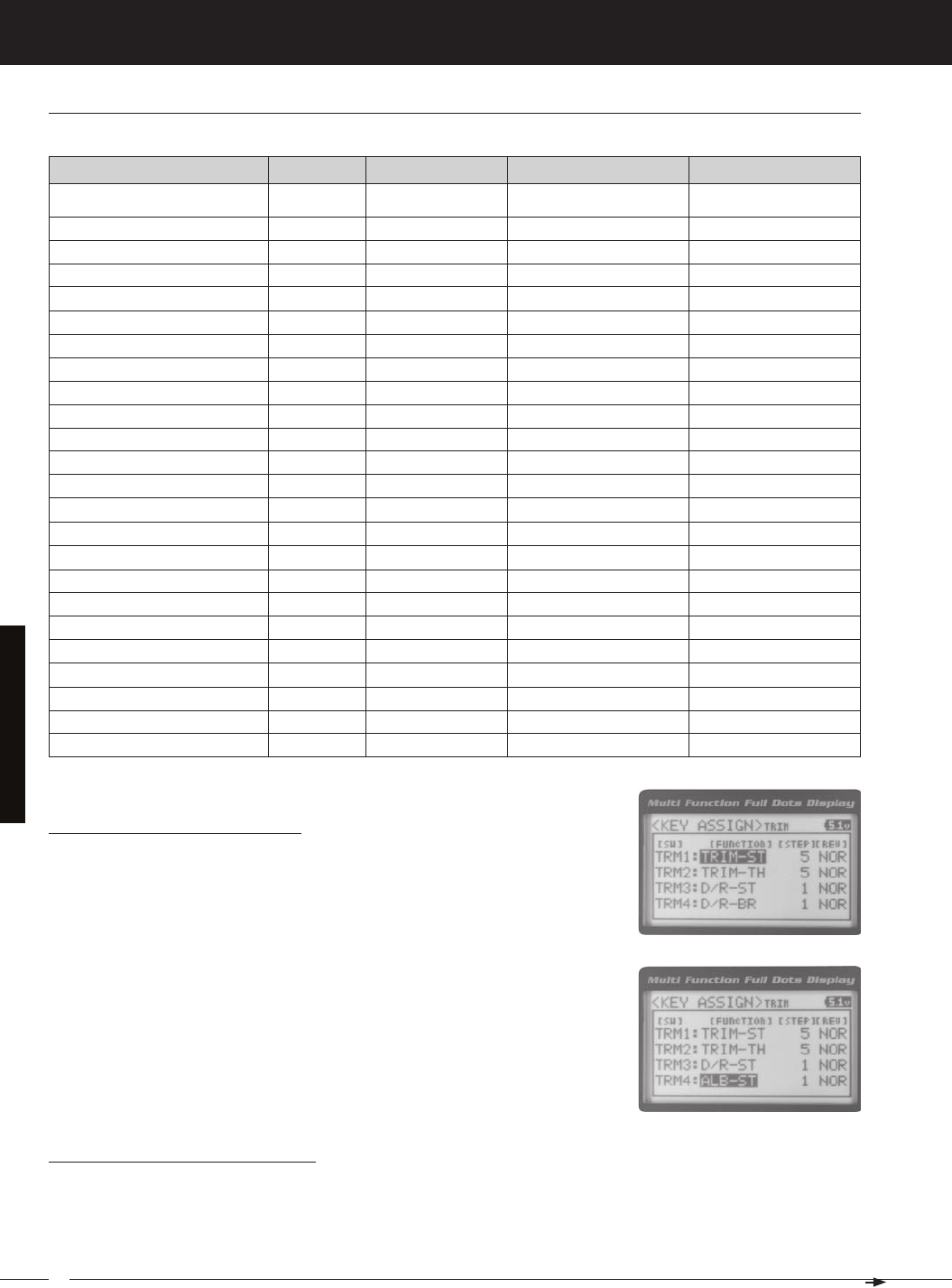
56
MT-4S 2.4GHZ FH4T RADIO SYSTEM USER'S GUIDE
T R
SySteM MenuS
TRIM-A1
TRIM-A2
D/R-ST
D/R-TH
D/R-BR
CU-R-ST
CU-P-ST
CU-R-TH
CU-P-TH
CU-R-BR
CU-P-BR
SP-ST-F
SP-ST-R
SP-TH-F
SP-TH-R
ALB-PO
ALB-ST
ALB-LG
ALB-HL
ALB-RE
OFFSET
AUX1
AUX2
Trim-Auxiliary 1
Trim-Auxiliary 2
Dual Rate-Steering
Dual Rate-Throttle
Dual Rate-Brake
Curve-Rate-Steering
Curve-Point-Steering
Curve-Rate-Throttle
Curve-Point-Throttle
Curve-Rate-Brake
Curve-Point-Brake
Speed-Steering-Forward
Speed-Steering-Return to Neutral
Speed-Throttle-Forward
Speed-Throttle-Return to Neutral
Anti-Lock Braking-Point
Anti-Lock Braking-Stroke
Anti-Lock Braking-Lag
Anti-Lock Braking-Hold
Anti-Lock Braking-Release
Throttle Offset
Auxiliary 1 Channel 3
Auxiliary 2 Channel 4
Trm3
Trm4
Rotary Dial
1
1
5
N/A
NOR
NOR
NOR
N/A
triM, dial and lever (triM, dial and lever key aSSiGnMentS) Continued....
Changing the Trim Switch Function
1) From within the KEY ASSIGN menu, scroll UP or DOWN to highlight TRIM.
2) Press the ENTER key. The TRIM menu will be displayed and TRM1 : TRIM-ST will
3) Scroll UP or DOWN to highlight the function you would like to change for either
TRM1, TRM2, TRM3 or TRM4.
4) Press the ENTER key, then scroll UP or DOWN to choose the desired function for
Trim Switch Trm1, Trm2, Trm3 or Trm4. A list of functions that can be assigned to
Changing the Trim Switch Step Value
The Step function allows you to adjust how far the servos travel when the Trim Switches are pressed. You can increase
the Trim Resolution by decreasing the Step value, so that the servos travel less when you press the Trim Switches. This
makes it possible to fine-tune servo movement extremely accurately. Alternately, you could decrease the Trim Resolution
by increasing the Step values, so that the servos travel more when you press the Trim Switches. This setting may not be
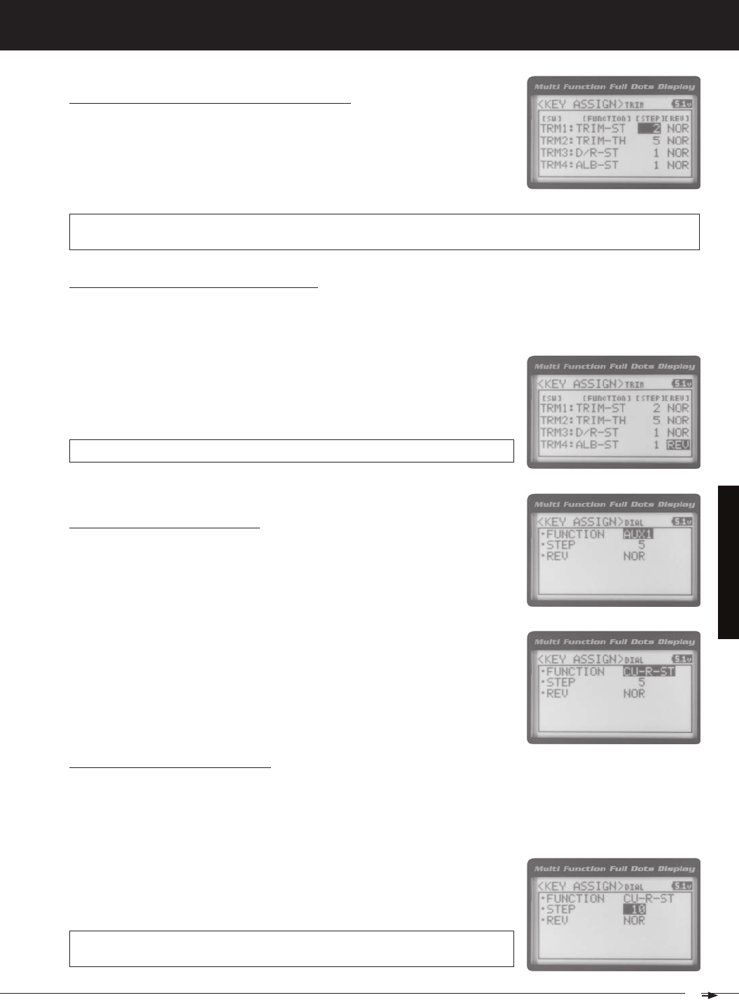
57
T R
MT-4S 2.4GHZ FH4T RADIO SYSTEM USER'S GUIDE
SySteM MenuS
Changing the Trim Switch Step Value, Continued....
1) From within the TRIM menu, scroll UP or DOWN to highlight the Step value you
would like to change for either TRM1, TRM2, TRM3 or TRM4.
2) Press the ENTER key, then scroll UP or DOWN to choose the desired Step value
TRIM STEP setting range is 1 to 100. The default setting for TRM1 is 5, for TRM2 is 5, for TRM3 is 1 and for TRM4 is 1. The
Step value is a percentage of servo travel.
Changing the Trim Switch Direction of Travel
The direction that the Trim Switches move the servos can be changed from Normal to Reverse. In Normal mode, the Trim
Switches will move the servos toward the High Side when the Trim Switches are pushed Forward. In Reverse mode, the
1) From within the TRIM menu, scroll UP or DOWN to highlight the REV value you
would like to change for either TRM1, TRM2, TRM3 or TRM4.
2) Press the ENTER key, then scroll UP or DOWN to choose the desired REV value
TRIM REV setting range is NOR and REV. The default setting for all Trim Switches is
Changing the Rotary Dial Function
1) From within the KEY ASSIGN menu, scroll UP or DOWN to highlight DIAL.
2) Press the ENTER key. The DIAL menu will be displayed and FUNCTION AUX1 will
3) Press the ENTER key, then scroll UP or DOWN to choose the desired function for
the Rotary Dial. A list of functions that can be assigned to the Rotary Dial is shown
Changing the Rotary Dial Step Value
The Step function allows you to adjust how far the servo travels when the Rotary Dial is turned. You can increase the
Dial Resolution by decreasing the Step value, so that the servo travels less when you turn the Rotary Dial. This makes
it possible to fine-tune servo movement extremely accurately. In addition, you could decrease the Dial Resolution by
increasing the Step value, so that the servo travels more when you turn the Rotary Dial. This setting may not be as ac-
1) From within the DIAL menu, scroll UP or DOWN to highlight STEP 5.
2) Press the ENTER key, then scroll UP or DOWN to choose the desired Step value
DIAL STEP setting range is 1 to 100. The default setting is 5. The Step value is a
percentage of servo travel.
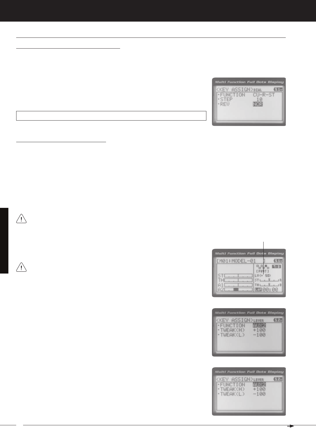
58
MT-4S 2.4GHZ FH4T RADIO SYSTEM USER'S GUIDE
T R
SySteM MenuS
Changing the Rotary Dial Direction of Travel
The direction that the Rotary Dial moves the servo can be changed from Normal to Reverse. In Normal mode, the Rotary
Dial will move the servo toward the High Side when the Rotary Dial is turned clockwise. In Reverse mode, the Rotary Dial
1) From within the DIAL menu, scroll UP or DOWN to highlight REV NOR.
2) Press the ENTER key, then scroll UP or DOWN to choose the desired REV value
DIAL REV setting range is NOR and REV. The default setting is NOR.
triM, dial and lever (triM, dial and lever key aSSiGnMentS) Continued....
Changing the Auxiliary Lever Function
In general, the Auxiliary Lever is used to control Auxiliary 1 Channel 3 or Auxiliary 2 Channel 4. Adjusting the High and Low
Tweak values determines how far and in which direction the Auxiliary servo travels when the Auxiliary Lever is moved Up
and Down. For example, if you assign AUX2 to the Auxiliary Lever and adjust the Tweak values to +50 and -50, the Auxiliary
2 servo will be centered when the Auxiliary Lever is centered and will travel 50% in one direction when the Auxiliary Lever
is moved Up and travel 50% in the other direction when the Auxiliary Lever is moved Down. This allows you to use the
Auxiliary Lever like a 2- or 3-position switch.
In addition, the Auxiliary Lever can be used to control the same parameter functions as the Trim Switches and the Rotary
Dial. For example, if you assign TRIM-ST and adjust the Tweak values to +100 and -100, the Auxiliary Lever will control
Steering channel Trim. The direction and amount the Trim moves when you move the Auxiliary Lever Up or Down is
To control either the Auxiliary 1 or the Auxiliary 2 servos using the Auxiliary Lever, the Auxiliary Type in the AUX TYPE
1) From within the KEY ASSIGN menu, scroll UP or DOWN to highlight LEVER.
2) Press the ENTER key. The LEVER menu will be displayed and FUNCTION AUX2
3) Press the ENTER key, then scroll UP or DOWN to choose the desired function for
the Auxiliary Lever. A list of functions that can be assigned to the Auxiliary Lever is
When you use the Auxiliary Lever to control a function, such as Steering Dual
Rate or Exponential, the change in values will not be displayed on the TOP
screen like they are when you use the Trim Switches or the Rotary Dial to make the
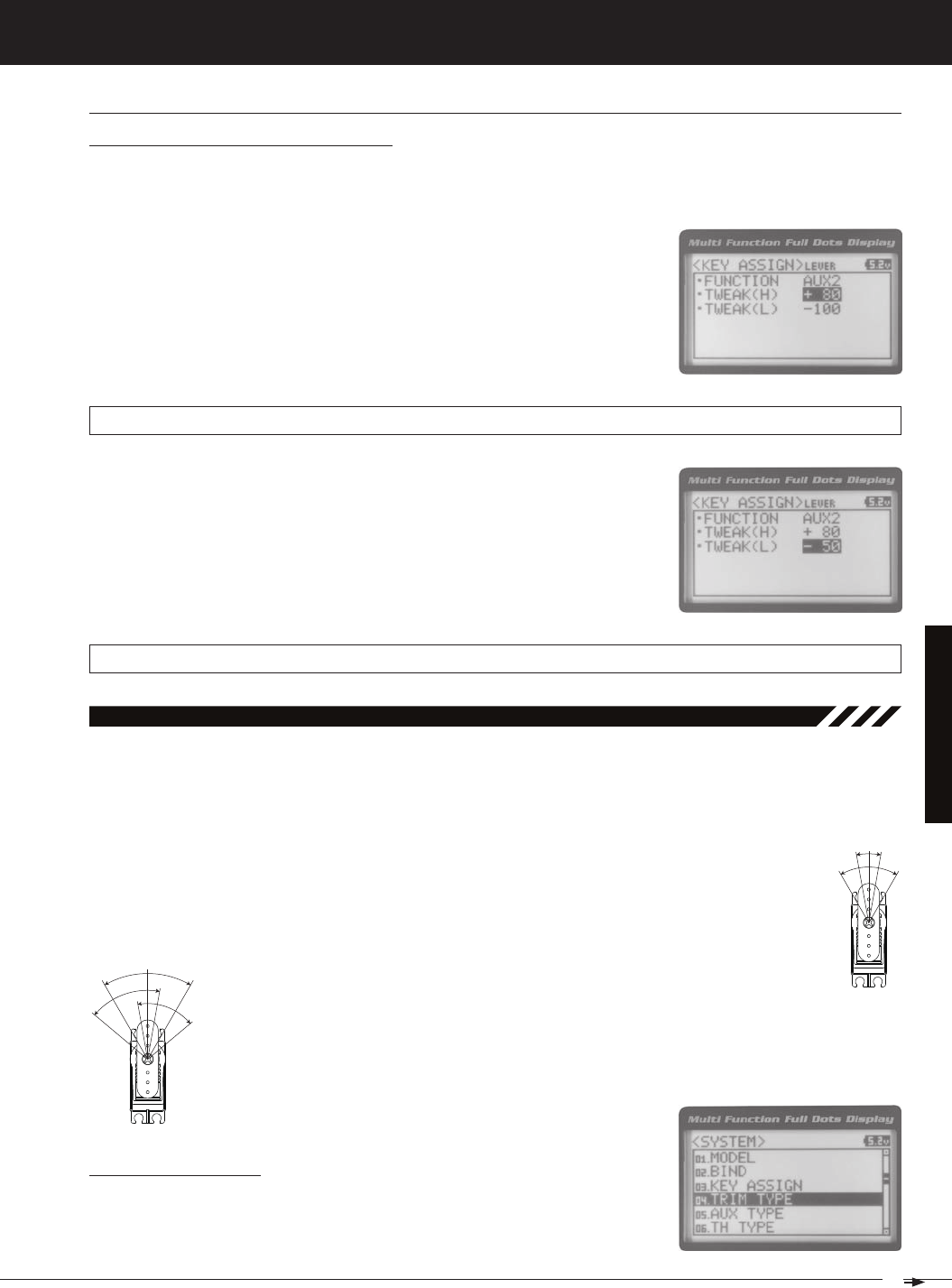
59
T R
MT-4S 2.4GHZ FH4T RADIO SYSTEM USER'S GUIDE
SySteM MenuS
04.triM tyPe (triM tyPe)
The Trim Type function allows you choose the way servo Trim and servo End Point Adjustments interact with each other.
When you apply Trim to a servo, the Neutral point of the servo shifts toward the High Side or the Low Side. When you do
this, the servo travels less in one direction and more in the other direction because the servo End Points are stationary. In
order to balance the servo travel, you would need to manually readjust the servo End Points. Using the Trim Type function
allows you to make the servo End Points shift toward the High Side or the Low Side when you apply Trim. This maintains
balanced servo travel without the need to manually readjust the servo End Points.
CENTER - When selected, servo End Points are stationary. In order to balance servo travel, you would need to
PARALLEL - When selected, servo End Points shift toward the High Side or the Low Side automatically
when you apply Trim. This maintains balanced servo travel without the need to manually readjust the
Changing the Trim Type
3) Scroll DOWN to highlight TWEAK(L) -100.
4) Press the ENTER key, then scroll UP or DOWN to choose the desired Low Side
Tweak value. Decreasing the Tweak value will increase servo travel in the Low
Side direction and increasing the Tweak value will decrease servo travel in the
LEVER TWEAK(L) setting range is -100 to +100. The default setting is -100.
1) From within the LEVER menu, scroll DOWN to highlight TWEAK(H) +100.
2) Press the ENTER key, then scroll UP or DOWN to choose the desired High Side
Tweak value. Increasing the Tweak value will increase servo travel in the High
Side direction and decreasing the Tweak value will decrease servo travel in the
LEVER TWEAK(H) setting range is -100 to +100. The default setting is +100.
Changing the High and Low Tweak Values
The High and Low Tweak values determine the direction and amount of Auxiliary 1 or Auxiliary 2 servo travel. In addition
the High and Low Tweak values determine the direction and amount of parameter function changes, such as Steering
triM, dial and lever (triM, dial and lever key aSSiGnMentS) Continued....
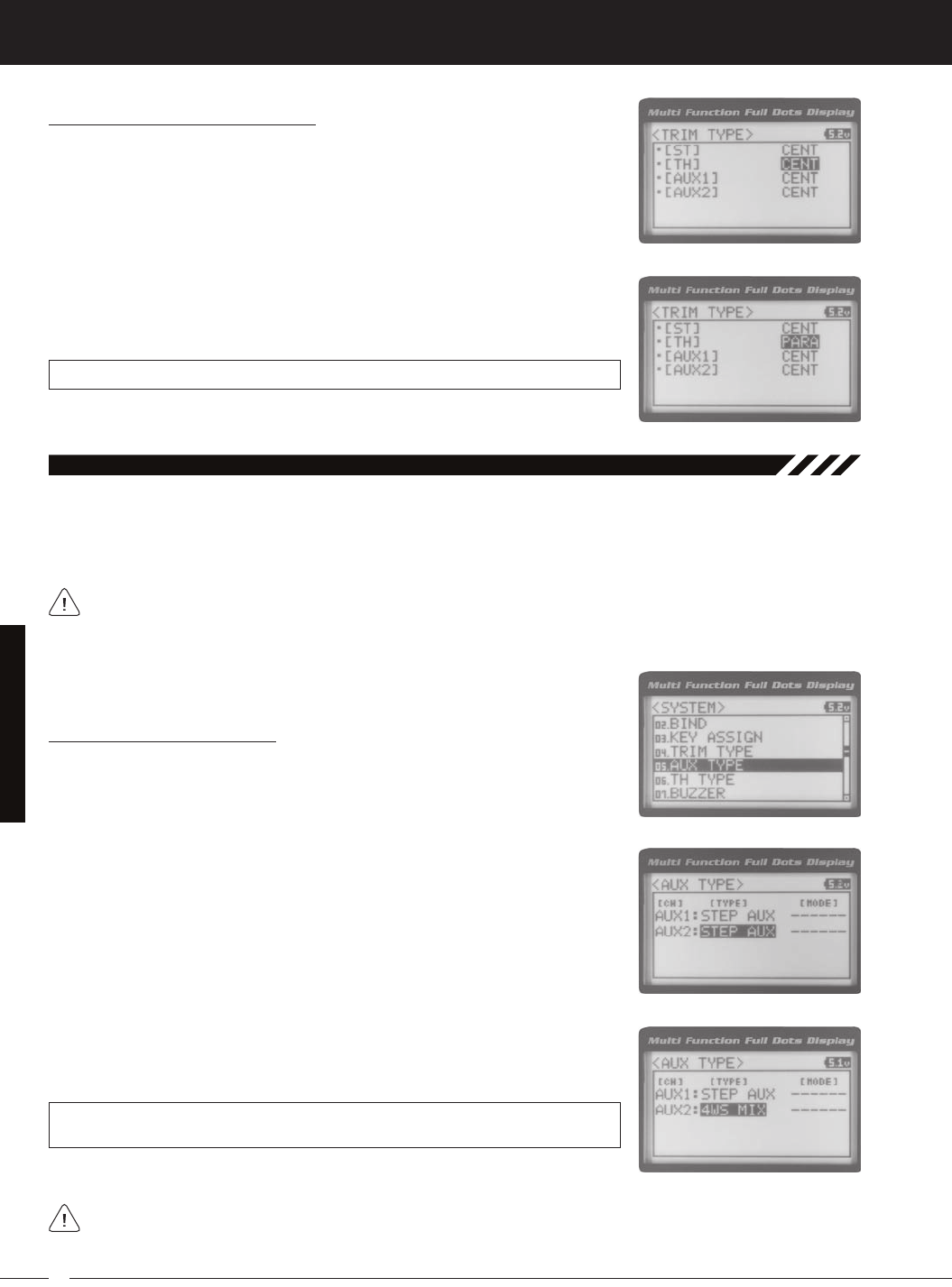
60
MT-4S 2.4GHZ FH4T RADIO SYSTEM USER'S GUIDE
T R
05.auX tyPe (auXiliary tyPe)
The Auxiliary Type function allows you choose which Auxiliary function is assigned to Auxiliary 1 Channel 3 or Auxiliary 2
Channel 4. One Auxiliary function can be assigned to each Auxiliary Channel and both Auxiliary Channels can be Active
and controlled at the same time using different controls. For example, you can control Auxiliary 1 Channel 3 using the
This section details how to assign the different Auxiliary functions to the Auxiliary Channels. For details about pro-
gramming and using each of the Auxiliary functions, see the Auxiliary 1 Programming section on pages 29 ~ 35 or
Changing the Auxiliary Function
2) Press the ENTER key. The AUX TYPE menu will be displayed and AUX1 : STEP
AUX will be highlighted.
3) Scroll UP or DOWN to highlight the desired channel you would like to change
4) Press the ENTER key, then scroll UP or DOWN to choose the desired Auxiliary
AUX TYPE setting range is STEP AUX, POINT AUX, 4WS MIX, MOA MIX and AUX MIX.
The default setting for both channels is STEP AUX.
Some Auxiliary functions allow you to change the Mode. Details of the various Mode options and how to
change them from within the Auxiliary Type function menu can be found in the specific Auxiliary function pro-
SySteM MenuS
Changing the Trim Type, Continued....
2) Press the ENTER key. The TRIM TYPE menu will be displayed and [ST] CENT will
be highlighted.
3) Scroll UP or DOWN to highlight the desired channel you would like to change
the Trim Type option for. Choose from either [ST] CENT (Steering), [TH] CENT
4) Press the ENTER key, then scroll UP or DOWN to choose the desired Trim Type
TRIM TYPE setting range is CENT and PARA. The default setting for all channels is
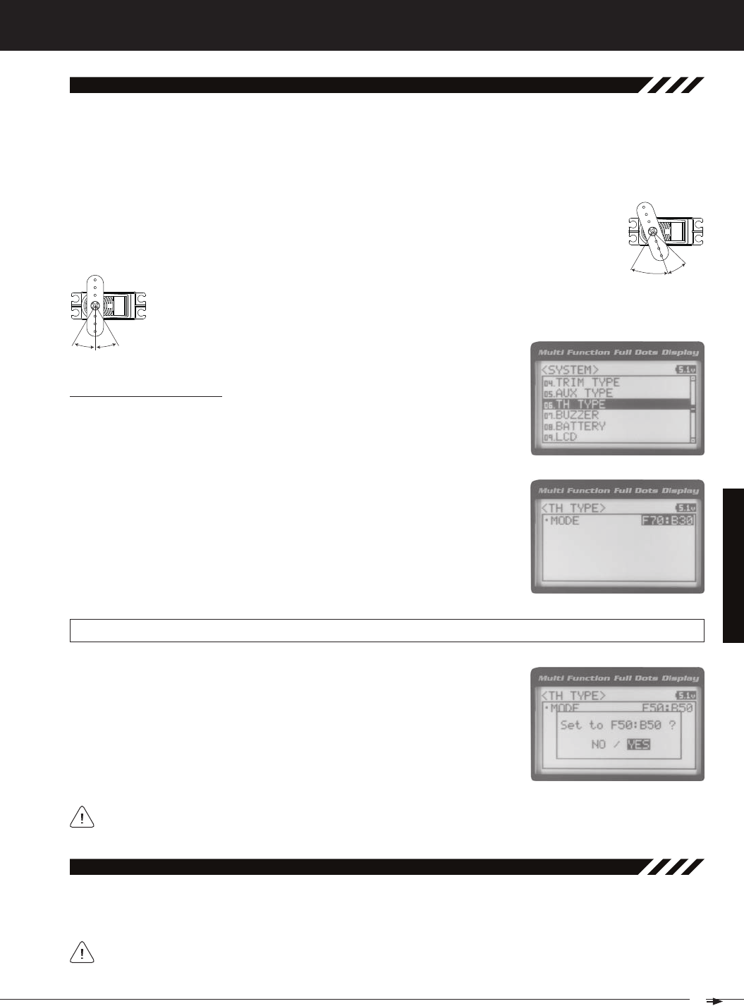
61
T R
MT-4S 2.4GHZ FH4T RADIO SYSTEM USER'S GUIDE
SySteM MenuS
06.tH tyPe (tHrottle tyPe)
The Throttle Type function allows you to change the proportion between Throttle High Side servo travel and Throttle
Brake Side servo travel. In the default configuration, the Throttle Type is set to F70:B30. This Throttle Type shifts the throt-
tle Neutral point toward the Brake Side, resulting in more servo travel toward the High Side and less servo travel toward
the Brake Side. Some users may prefer the proportion between Throttle High Side servo travel and Throttle Brake Side
servo travel to be balanced (F50:B50). The F70:B30 Throttle Type is most common for general use and racing, while the
F50:B50 Throttle Type is most common for Rock Crawling.
F70:B30 - When selected, the throttle Neutral point is shifted toward the Brake Side. This is most common
Changing the Throttle Type
2) Press the ENTER key. The TH TYPE menu will be displayed and MODE F70:B30
will be highlighted.
3) Press the ENTER key, then scroll UP or DOWN to choose the desired Throttle Type
TH TYPE setting range is F70:B30 and F50:B50. The default setting is F70:B30.
The current Throttle Type will be displayed on the TOP screen. 7:3 will be displayed to indicate the current
4) Press the ENTER key. Either Set to F70:B30? NO/YES will be displayed or Set to
F50:B50? NO/YES will be displayed. Scroll DOWN to highlight YES, then press the
07.buzzer (audible key tone)
The Audible Key Tone function allows you to change the Volume and Tone of the audible sounds that are made when
you use the Trim Switches, Rotary Dial, Auxiliary Lever, Push-Button Rotary Dial and the Timer function. The Volume can
Changes made using the Audible Key Tone function also affect the audible sounds that are part of the Timer
function. For example, if you Mute the Audible Key Tones, the sounds that are part of the Timer function will
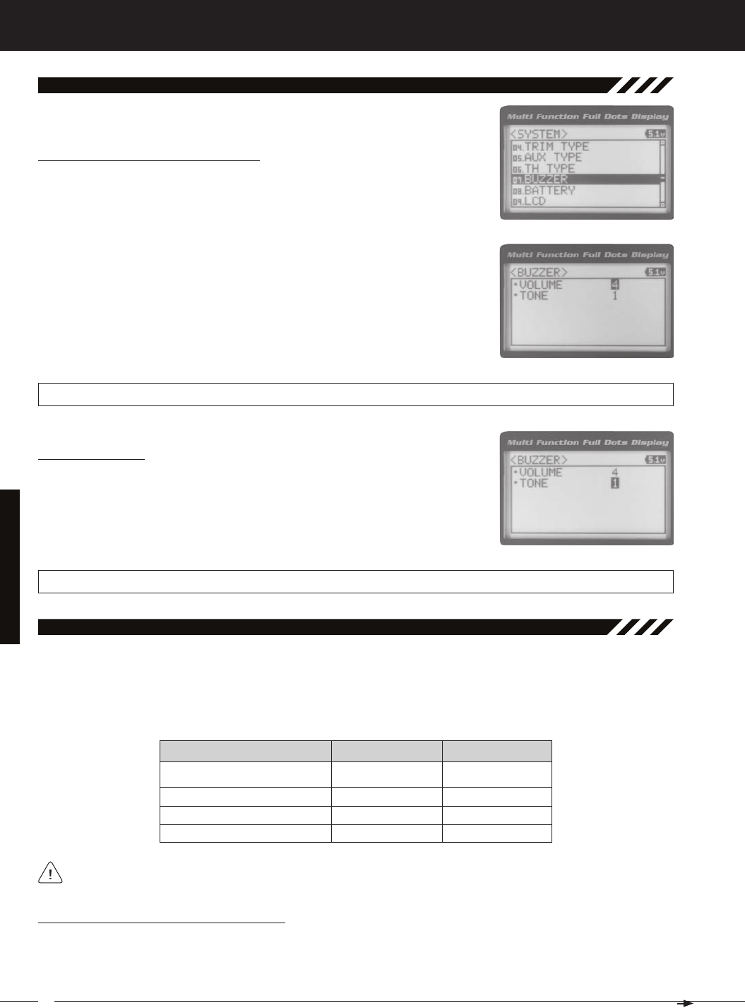
62
MT-4S 2.4GHZ FH4T RADIO SYSTEM USER'S GUIDE
T R
SySteM MenuS
Changing the Audible Key Tone Volume
2) Press the ENTER key. The BUZZER menu will be displayed and VOLUME 4 will be
highlighted.
3) Press the ENTER key, then scroll UP or DOWN to choose the desired Volume
value. Increasing the Volume value will increase the Volume of the Audible Key
BUZZER VOLUME setting range is OFF to 5. The default setting is 4. When OFF is selected, Audible Key Tones will be
Changing the Tone
1) From within the BUZZER menu, scroll DOWN to highlight TONE 1.
2) Press the ENTER key, then scroll UP or DOWN to choose the desired Tone value.
Increasing the Tone value will increase the Tone of the Audible Key Tones and de-
BUZZER TONE setting range is 1 to 7. The default setting is 1.
07.buzzer (audible key tone), Continued....
08.battery (voltaGe alarM)
The Voltage Alarm function allows to specify the voltage at which the Low Voltage Alert and Low Voltage Limit alarms
will sound. This allows you to choose custom voltage settings to match the type of transmitter battery you're using. For
example,if you're using a 6 cell Ni-MH battery pack or a 2S Li-Po battery pack, you can set the Low Voltage Alert alarm
Changing the Low Voltage Alert Alarm Value
The Low Voltage Alert alarm will sound to indicate the transmitter batteries are getting low and should be replaced or
recharged. We suggest stopping use as soon as safely possible and replacing or recharging the transmitter batteries.
The Low Voltage Alert alarm will sound each time the transmitter battery voltage decreases by 0.1 volt. To clear this alarm,
4.6 Volts
7.0 Volts
7.2 Volts
4 Cell Alkaline
6 Cell Ni-CD/Ni-MH
2S Li-Po
4.4 Volts
6.6 Volts
6.8 Volts
To ensure the safety of your model and your transmitter battery, we suggest using the Alert and Limit Voltage
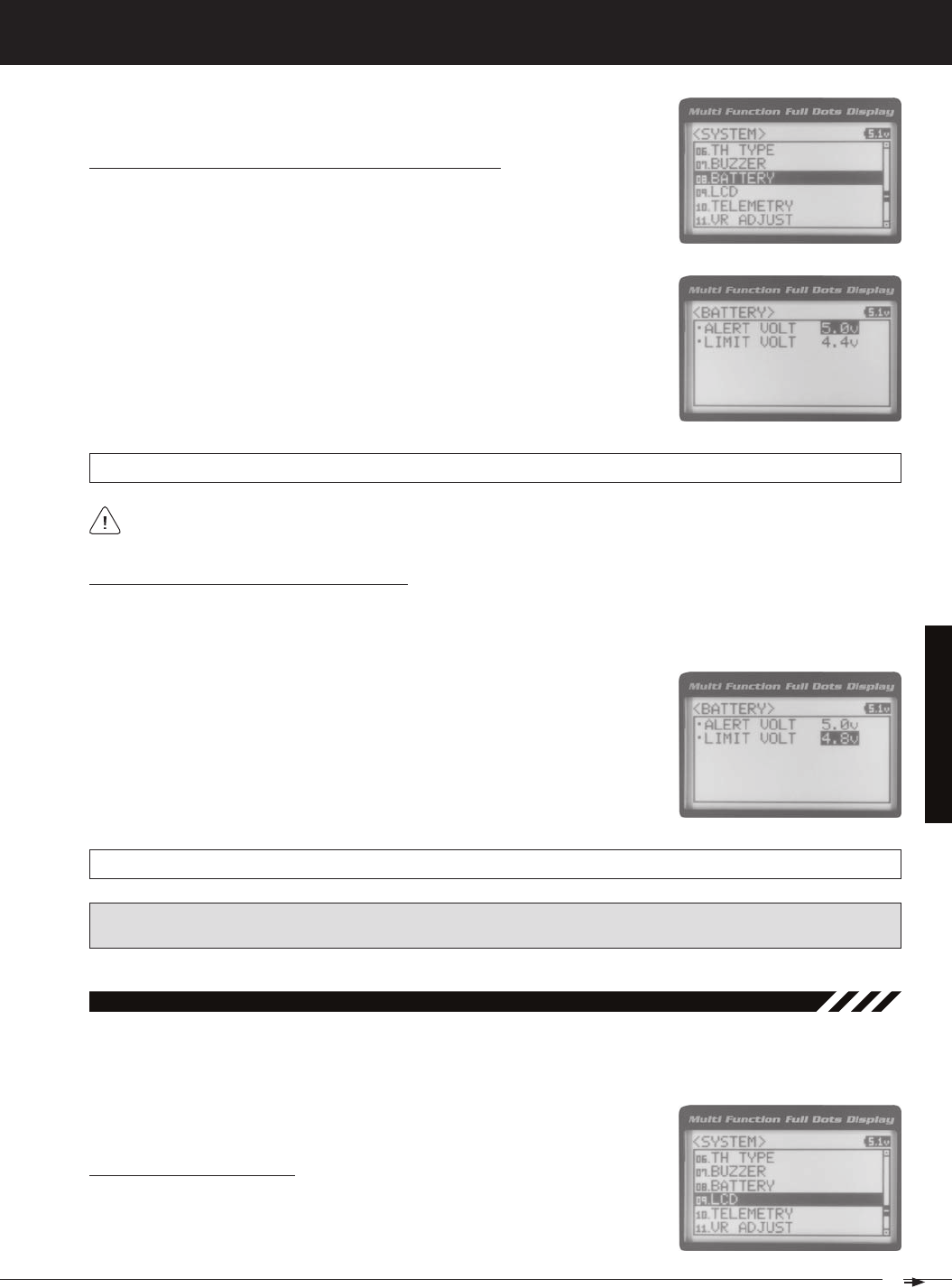
63
T R
MT-4S 2.4GHZ FH4T RADIO SYSTEM USER'S GUIDE
SySteM MenuS
2) Press the ENTER key. The BATTERY menu will be displayed and ALERT VOLT 4.6v
will be highlighted.
3) Press the ENTER key, then scroll UP or DOWN to choose the desired Low Voltage
Alert alarm value. Increasing the Low Voltage Alert alarm value will cause the Low
Voltage Alert alarm to sound at a higher voltage and decreasing the Low Voltage
BATTERY ALERT VOLT setting range is 4.1v to 9.0v. The default setting is 4.6v.
Changing the Low Voltage Alert Alarm Value, Continued....
1) From within the BATTERY menu, scroll DOWN to highlight LIMIT VOLT 4.4v.
2) Press the ENTER key, then scroll UP or DOWN to choose the desired Low Voltage
Limit alarm value. Increasing the Low Voltage Limit alarm value will cause the
Low Voltage Limit alarm to sound at a higher voltage and decreasing the Low
Changing the Low Voltage Limit Alarm Value
The Low Voltage Limit alarm will sound to indicate the transmitter batteries are dangerously low and should be re-
placed or recharged right away. The Low Voltage Limit alarm cannot be cancelled. When the Low Voltage Limit alarm
BATTERY LIMIT VOLT setting range is 4.0v to 4.9v. The default setting is 4.4v.
WARNING: Continuing to use the transmitter after the Low Voltage Limit alarm sounds can result in loss of control of
your model. When the Low Voltage Alert alarm sounds, stop use as soon as is safe, then replace or recharge the trans-
9.lCd (lCd ContraSt)
The LCD Contrast function allows you to change the contrast of the Multi-Function LCD to make it easier to read in all
types of lighting conditions. In general, increasing the Contrast will make the Multi-Function LCD easier to read in bright
Changing the Contrast Value
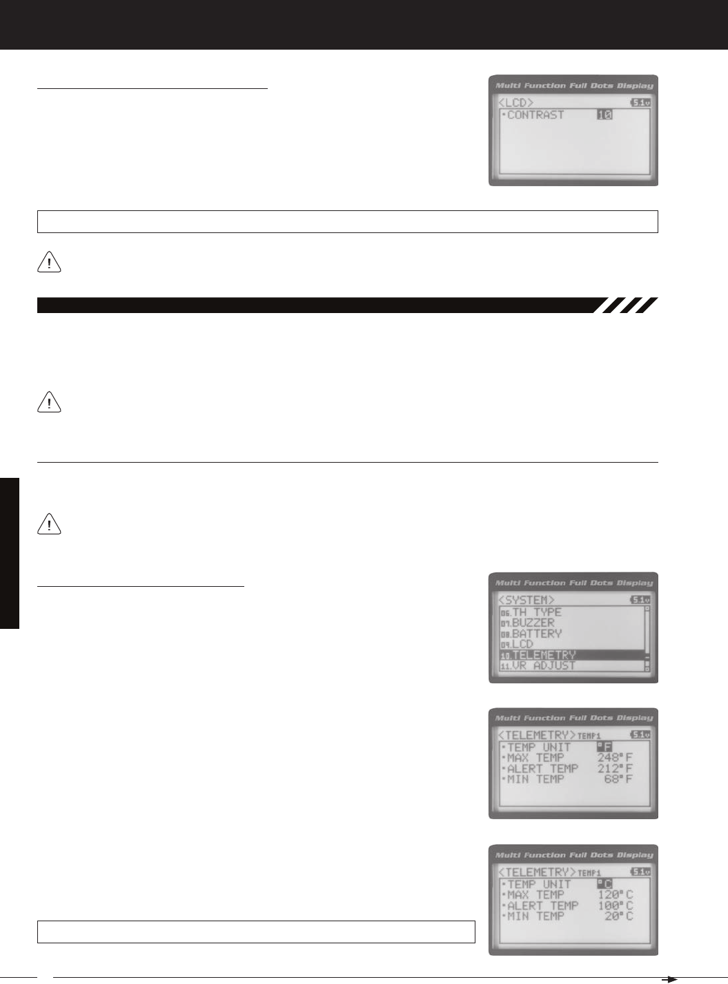
64
MT-4S 2.4GHZ FH4T RADIO SYSTEM USER'S GUIDE
T R
SySteM MenuS
Increasing or decreasing the LCD Contrast values to the extreme limits can result in blacking out the Multi-Function
Changing the Contrast Value, Continued....
2) Press the ENTER key. The LCD menu will be displayed and CONTRAST 15 will be
highlighted.
3) Press the ENTER key, then scroll UP or DOWN to choose the desired LCD Con-
trast value. Increasing the LCD Contrast value will increase the Contrast of the
Multi-Function LCD and decreasing the LCD Contrast value will decrease the
LCD CONTRAST setting range is 0 to 30. The default setting is 15.
10.teleMetry (teleMetry)
The Telemetry menu allows you to change different options to configure how the various Telemetry functions are dis-
played on the Telemetry Screen, and how the Telemetry Logger operates. For example, you are able to change the
Telemetry Temperature reading from Fahrenheit to Celsius, change the values at which Telemetry Sensor alarms sound
For information about plugging the Telemetry Sensors into your receiver and installing them into your model, see
the Telemetry Connections and Mounting section on page 13. For information about using the Telemetry function,
teMP1 and teMP2 SettinG (teMPerature teleMetry diSPlay oPtionS)
The Temperature 1 and Temperature 2 Settings allow you change how Temperature information is displayed on the
3) Scroll UP or DOWN to highlight TEMP1 SETTING or TEMP2 SETTING.
4) Press the ENTER key. The TEMP1 or TEMP2 menu will be displayed and TEMP
5) Press the ENTER key, then scroll UP or DOWN to change the Temperature Unit
to the desired value. When ºF is chosen, all Telemetry Temperatures will be dis-
played in Fahrenheit and when ºC is chosen, all Telemetry Temperatures will be
TELEMETRY TEMP UNIT setting range is ºF and ºC. The default setting is ºF.
The MT-4 2.4GHz FHSS-4T radio control system includes one Temperature Sensor. If you want to utilize both Tem-
perature Inputs on the receiver at the same time, you will need to purchase a second Temperature Sensor sepa-
Changing the Temperature Unit Value
If desired, the Temperature Unit value can be changed from Fahrenheit to Celsius.
1) From within the SYSTEM menu, scroll UP or DOWN to highlight the TELEMETRY
menu.
2) Press the ENTER key. The TELEMETRY menu will be displayed and TEMP1 SET-
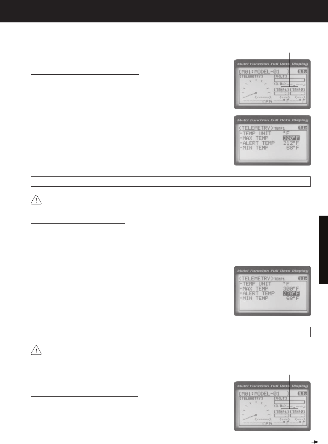
65
T R
MT-4S 2.4GHZ FH4T RADIO SYSTEM USER'S GUIDE
SySteM MenuS
1) From within the TEMP1 or TEMP2 menu, scroll UP or DOWN to highlight MAX
TEMP 248ºF (or 120ºC).
2) Press the ENTER key, then scroll UP or DOWN to change the Maximum Tem-
perature value. The Temperature Display Monitor on the Telemetry Screen will
Changing the Maximum Temperature Value
The Maximum Temperature value determines the maximum temperature shown on
the [TEMP1] or [TEMP2] Telemetry Screen Temperature Display Monitors. This allows
you to calibrate each Temperature Display Monitor to match what the Tempera-
TELEMETRY MAX TEMP setting range is 68ºF to 302ºF (0ºC to 150ºC). The default setting is 248ºF (120ºC).
The Maximum Temperature value cannot be set lower than the Alert Temperature value or the Minimum Tempera-
1) From within the TEMP1 or TEMP2 menu, scroll UP or DOWN to highlight ALERT
TEMP 212ºF (or 100ºC).
2) Press the ENTER key, then scroll UP or DOWN to change the Alert Temperature
value. The Alert Temperature value is the temperature that the Temperature
Changing the Alert Temperature Value
The Alert Temperature value determines the temperature at which the Temperature Alert alarm will sound. For example,
you can set an Alert Temperature value for your Nitro engine that will alert you when your engine's cylinder head tem-
perature is getting too hot. When the Alert Temperature value is reached, the Temperature Alert alarm will sound and
LED2 (Red) will flash. The Temperature Alert alarm will sound for approximately 5 seconds, however, LED2 will con-
tinue to flash until the temperature drops below the Alert Temperature value. The audible portion of the Temperature
TELEMETRY ALERT TEMP setting range is 68ºF to 302ºF (0ºC to 150ºC). The default setting is 212ºF (100ºC).
The Alert Temperature value cannot be set higher than the Maximum Temperature value. In addition, the Alert
Temperature value cannot be set lower than the Minimum Temperature value. In some cases, you may need to
Changing the Minimum Temperature Value
The Minimum Temperature value determines the Minimum temperature shown on
the [TEMP1] or [TEMP2] Telemetry Screen Temperature Display Monitors. This al-
lows you to calibrate each Temperature Display Monitor to match what the Tem-
teMP1 and teMP2 SettinG (teMPerature teleMetry diSPlay oPtionS), Continued....
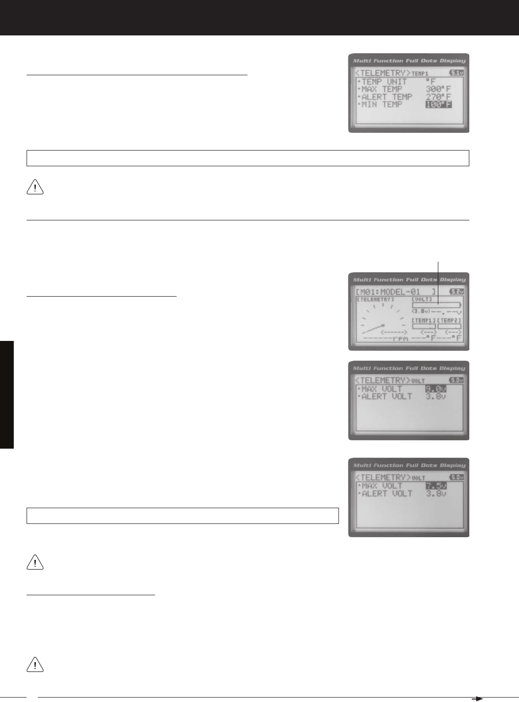
66
MT-4S 2.4GHZ FH4T RADIO SYSTEM USER'S GUIDE
T R
SySteM MenuS
Changing the Minimum Temperature Value, Continued....
1) From within the TEMP1 or TEMP2 menu, scroll UP or DOWN to highlight MIN
TEMP 68ºF (or 20ºC).
2) Press the ENTER key, then scroll UP or DOWN to change the Minimum Tem-
perature value. The Temperature Display Monitor on the Telemetry screen will
TELEMETRY MIN TEMP setting range is 32ºF to 302ºF (0ºC to 150ºC). The default setting is 68ºF (20ºC).
The Minimum Temperature value cannot be set higher than the Alert Temperature value or the Maximum
volt SettinG (reCeiver battery voltaGe teleMetry diSPlay oPtionS)
The Voltage Setting you to change the way receiver battery Voltage information is displayed on the Telemetry Screen
1) From within the TELEMETRY menu, scroll UP or DOWN to highlight VOLT SET-
TING.
Changing the Maximum Voltage Value
The Maximum Voltage value determines the maximum receiver battery Voltage that
will be shown on the [VOLT] Telemetry Screen Display Monitor. This allows you to
calibrate the Voltage Display Monitor to match your model's receiver battery. This
The Maximum Voltage value cannot be set lower than the Alert Voltage value. If necessary, you may need to lower
TELEMETRY MAX VOLT setting range is 3.0v to 9.0v. The default setting is 9.0v.
3) Press the ENTER key, then scroll UP or DOWN to change the Maximum Voltage
value. The Voltage Display Monitor on the Telemetry Screen will not display re-
Changing the Alert Voltage Value
The Alert Voltage value determines the voltage at which the Voltage Alert alarm will sound. For example, you can set the
Alert Voltage value to alert you to when your model's receiver battery is getting low and needs to be recharged. When
the Alert Voltage value is reached, the Voltage Alert alarm will sound and LED2 (Red) will flash. The Voltage Alert alarm
will sound for approximately 5 seconds, however, LED2 will continue to flash until you recharge the receiver battery. The
Refer to the manufacturer of your model's receiver battery to determine the safest Alert Voltage value to use. In
general, the Alert Voltage value should be high enough to alert you when it's time to recharge your receiver battery,
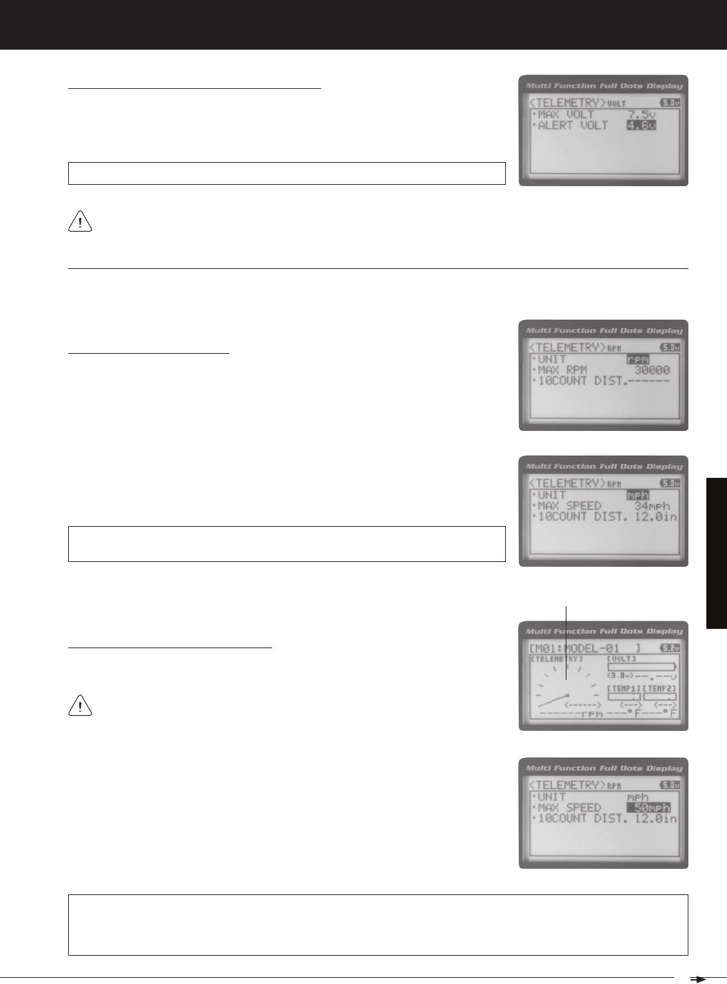
67
T R
MT-4S 2.4GHZ FH4T RADIO SYSTEM USER'S GUIDE
SySteM MenuS
Changing the Alert Voltage Value, Continued....
1) From within the VOLT menu, scroll UP or DOWN to highlight ALERT VOLT 3.8v.
2) Press the ENTER key, then scroll UP or DOWN to change the Alert Voltage value.
TELEMETRY ALERT VOLT setting range is 3.0v to 9.0v. The default setting is 3.8v.
The Alert Voltage value cannot be set higher than the Maximum Voltage value. In some cases, you may need to
rPM SettinG (rPM teleMetry diSPlay oPtionS)
The RPM Setting allows you to change the way RPM information is displayed on the Telemetry Screen. For example, you
can choose to display RPMs, MPH or KM/H. In addition, if MPH or KM/H is chosen, the RPM sensor can be calibrated
Changing the RPM Unit Value
1) From within the TELEMETRY menu, scroll UP or DOWN to highlight RPM SET-
TING.
3) Press the ENTER key, then scroll UP or DOWN to change the RPM Unit to the
desired value. When RPM is chosen, the Revolutions Per Minute of whatever the
RPM Sensor is attached to will displayed. When MPH or KM/H is chosen, the
TELEMETRY RPM UNIT setting range is RPM, MPH and KM/H. The default setting
is RPM.
1) From within the RPM menu, scroll UP or DOWN to highlight MAX RPM 30000 (or
MAX SPEED 34mph or MAX SPEED 54km/h).
2) Press the ENTER key, then scroll UP or DOWN to change the Maximum RPM or
Maximum Speed value. The RPM Gauge on the Telemetry Screen will not display
TELEMETRY MAX RPM setting range is 500 to 127500. The default setting is 30000. TELEMETRY MAX SPEED setting
range is 1mph to 335mph (1km/h to 539km/h). The default setting is 34mph (54km/h). The Maximum Speed setting
range will vary based on the 10 Count Distance value programmed when you calibrate the RPM Sensor. For more
information, see the Calibrating the RPM Sensor section on page 70.
Changing the Maximum Speed Value
The Maximum Speed value determines the maximum RPM or Speed value that will
The RPM Gauge and RPM Digital Display names will change from RPM to MPH
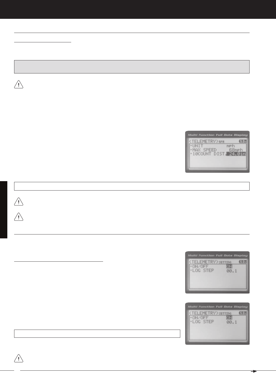
68
MT-4S 2.4GHZ FH4T RADIO SYSTEM USER'S GUIDE
T R
rPM SettinG (rPM teleMetry diSPlay oPtionS), Continued....
Calibrating the RPM Sensor
When you choose to use the RPM Sensor to display MPH or KM/H, the RPM Sensor must be calibrated to ensure that
3) From within the RPM menu, scroll UP or DOWN to highlight 10COUNT DIST.
12.0in (or 10COUNT DIST. 30cm).
4) Press the ENTER key, then scroll UP or DOWN to change the 10 Count Distance
value to the measurement obtained in step 2 above. For example, if your mod-
1) With the MT-4 2.4GHz FHSS-4T radio control system turned ON and the RPM Sensor installed on your model as de-
scribed in the Mounting the RPM Sensor section page 13, place your model on the ground.
2) Measuring from where you set your model on the ground, push your model and measure the distance covered to
When the reflective tape attached to your model's clutch bell, flywheel, etc., crosses the RPM sensor, the Bind
IMPORTANT: Prior to Calibrating the RPM Sensor, you must connect the RPM Sensor to the receiver and correctly
install the RPM Sensor onto your model. For more information, see the Mounting the RPM Sensor section page 13.
TELEMETRY 10COUNT DIST setting range is 0.5in to 118.0in (1cm to 300cm). The default setting is 12.0in (30cm).
RPM Sensor calibration is only required if you choose to use the RPM Sensor to display MPH or KM/H. Calibration
teleMetry SettinG (teleMetry and teleMetry loG oPtionS)
The Telemetry Setting allows you to choose whether the Telemetry System is turned ON or OFF and change the interval
3) Press the ENTER key, then scroll UP or DOWN to change the Telemetry ON/
OFF value. When ON is selected, the Telemetry System is turned ON. When OFF is
TELEMETRY SETTING ON/OFF setting range is ON or OFF. The default setting is
Turning the Telemetry System ON and OFF
1) From within the TELEMETRY menu, scroll UP or DOWN to highlight TELEMETRY
SETTING.
2) Press the ENTER key. The SETTING menu will be displayed and ON/OFF ON
SySteM MenuS
Adjusting the 10 Count Distance value will change the Maximum Speed value you changed in the previous step.
If the Telemetry Log function is started when the Telemetry System is OFF, default values will be stored in the
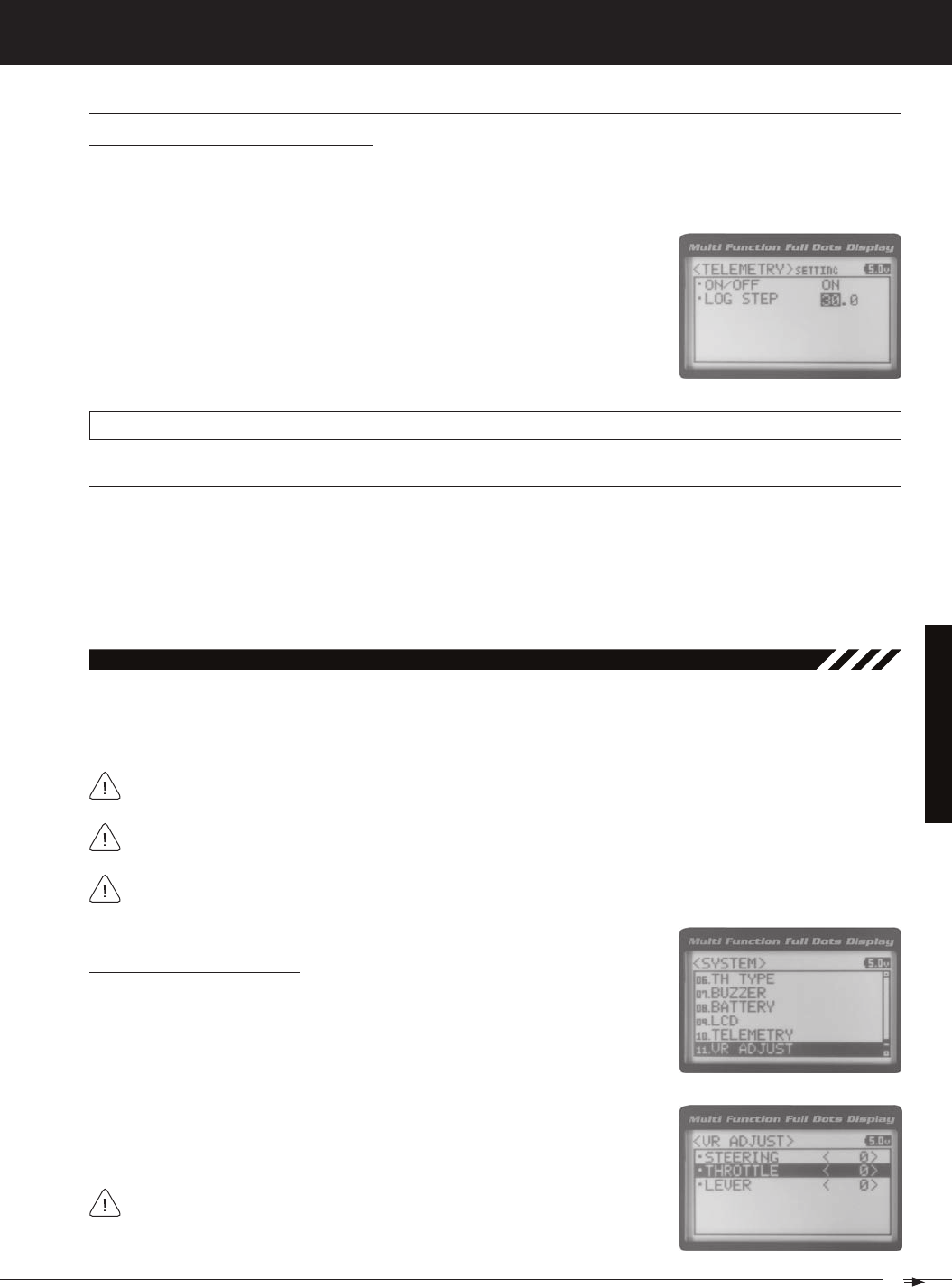
69
T R
MT-4S 2.4GHZ FH4T RADIO SYSTEM USER'S GUIDE
teleMetry SettinG (teleMetry loG oPtionS), Continued....
Changing the Telemetry Log Step Value
The Telemetry Log Step value can be changed to customize how much Telemetry Data and the time interval Telemetry
Data is recorded. The Telemetry Log can store up to 120 separate entries. If the Log Step value is set to 00.1 seconds, the
TELEMETRY LOG STEP setting range is 00.1 to 45.9. The default setting is 00.1.
1) From within the SETTING menu, scroll UP or DOWN to highlight LOG STEP 00.1.
2) Press the ENTER key, then scroll UP or DOWN to change the Telemetry Log Step
value. Programming a lower Telemetry Log Step value results in narrower, high-
er resolution readings, but for a shorter period of time. Programming a higher
Telemetry Log Step value results in broader, lower resolution readings, but for
11.vr adjuSt (variable rate adjuStMent)
Over time during use, it's possible that the End Points and/or Neutral positions of the controls may change slightly or
you may purposely limit the travel of the Steering Wheel to suit the best feel of the steering wheel and your driving style.
The Variable Rate Adjustment function allows you to calibrate the operation of the Steering Wheel, Throttle Trigger and
After using the Variable Rate Adjustment function, you should double-check the End Point Adjustments of each
Calibrating Control Operation
1) From within the SYSTEM menu, scroll UP or DOWN to highlight the VR ADJUST
menu.
3) Scroll UP or DOWN to highlight the control you would like to calibrate. Choose
<0> indicates the current position of the specific channel relative to its specific
control. For example, if the Steering Wheel is in the Neutral position, but an L or
SySteM MenuS
We recommend using this function as part of a periodic maintenance schedule or after adjusting Steering Wheel
te-Clr (teleMetry Clear funCtion)
The Telemetry Clear function allows you to Reset the High Temperature 1, High Temperature 2 and High RPM values that
are displayed on the Telemetry Screen. The Telemetry Clear function can be assigned to either Push-Button Switch Sw1 or
Push-Button Switch Sw2. When you press the Push-Button Switch the Telemetry Clear function is assigned to, the High
Temperature 1, High Temperature 2 and High RPM values will be Reset the Current values read by the Telemetry Sensors.
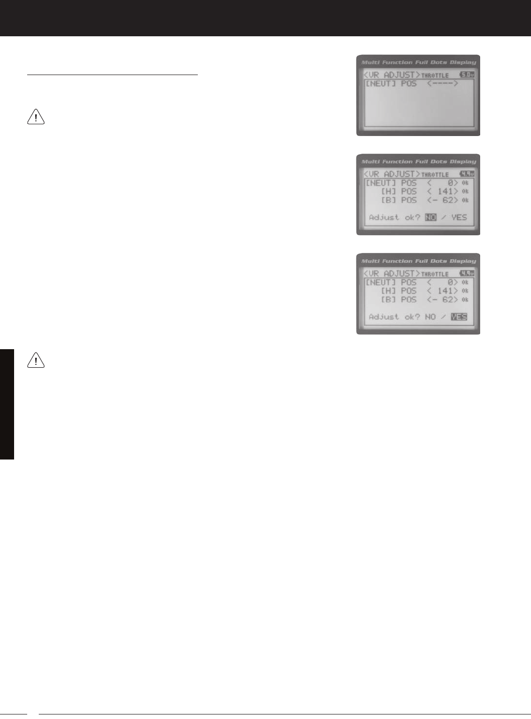
70
MT-4S 2.4GHZ FH4T RADIO SYSTEM USER'S GUIDE
T R
Calibrating Control Operation, Continued....
4) With the Steering Wheel, Throttle Trigger or Auxiliary Lever in the Neutral position,
5) Press the ENTER key a second time. A menu with several position indicators will
be displayed.
6) Slowly move the Steering Wheel, Throttle Trigger or Auxiliary Lever all the way in
one direction. Allow the control to return to Neutral, then slowly move the Steering
Wheel, Throttle Trigger or Auxiliary Lever all the way in the opposite direction. A
7) Scroll DOWN to highlight YES, then press the ENTER key. Executed will flash,
To cancel the calibration process, scroll UP or DOWN to highlight NO, then press the ENTER key. You can then
SySteM MenuS
THIS SPACE INTENTIONALLY LEFT BLANK

71
T R
MT-4S 2.4GHZ FH4T RADIO SYSTEM USER'S GUIDE
Transmitter does not turn ON
Transmitter will not bind to receiver
Alarm beeps continuously
No sound when keys are pressed
No Timer function sounds
Servo movement is slow
Servo does not move when using Trim Switch
Inadequate transmitting range
Servo moves too much, or doesn't move
enough, when Trim Switch is moved
Throttle servo or ESC moves to programmed
position without input
Cannot program receiver Battery Fail Safe
Voltage level
No Telemetry connection
RPM Sensor not functioning
referenCe
This troubleshooting guide can help you diagnose and solve some of the more common problems that you may encounter
with your MT-4 2.4GHz FHSS-4T radio control system. If you cannot solve the problem using this troubleshooting guide,
ProbleM CauSe Solution
Batteries not installed correctly Reinstall batteries. Observe correct polarity
Battery tray not plugged in Plug in battery tray. Observe correct polarity
Damage caused by using incorrect Contact Airtronics Customer Service
charger or reverse polarity
Low transmitter battery voltage Replace or recharge transmitter batteries
Modulation incorrect Change Modulation Type to match receiver
Too much time elapsed after pressing Quickly press the ENTER key
in the BIND menu receiver Bind Button a f t e r
releasing the receiver Bind Button
Attempting to bind incompatible Use only Airtronics 2.4GHz FHSS-2, FHSS-3
or
receiver FHSS-4T surfaces receivers
Using ESC with BEC Disconnect ESC and use dry cell battery for
Binding
procedure, then reconnect ESC after binding
Low receiver battery voltage Recharge receiver battery
Transmitter battery voltage at Low Replace or recharge transmitter batteries
Voltage Limit
Transmitter left ON more than 10 Move steering wheel or throttle trigger, or press
any
minutes without control input button to continue use
Audible Key Tones are Muted Increase Audible Key Tone volume
Audible Key Tones are Muted Increase Audible Key Tone volume
Receiver battery voltage low Recharge receiver battery
A negative Servo Speed value is Increase Servo Speed Programming Value
programmed
Control linkages binding Adjust control linkages to operate smoothly
Trim is outside of operational range Reset Trim to zero and center the servo
horn and
control linkage
Low transmitter or receiver battery Replace or recharge transmitter and receiver
batteries
voltage
Receiver antenna not mounted Mount receiver antenna as recommended
correctly in your model
Trim Step resolution requires Adjust Trim Step resolution
adjustment
Receiver battery voltage has reached Recharge receiver battery
the programmed Battery Fail Safe
voltage level
Throttle channel Fail Safe set to FREE Set Throttle channel Fail Safe to a percentage
value
or HOLD
Using FHSS-2 or FHSS-3 receiver Use FHSS-4T receiver
Telemetry System turned OFF Turn Telemetry System ON
Distance between transmitter and Shorten distance between transmitter and
receiver
receiver too far
Sensor Pickup not facing reflective Mount RPM Sensor so that Sensor Pickup
faces
troubleSHootinG Guide

72
MT-4S 2.4GHZ FH4T RADIO SYSTEM USER'S GUIDE
T R
referenCe
Activate: To turn ON a particular function.
Antenna: Transmits the signal from the transmitter to the receiver in the model. Never touch the Antenna during use. Do-
ing so may result in a weakened RF signal or complete loss of control of your model.
Antenna Reception Wire: The portion of the receiver antenna that receives the transmitter signal. The Antenna Reception
Wire should never be bent or it could be damaged and limit the range of your model.
Anti-Lock Braking: Makes it possible to achieve stable braking even on slippery surfaces. With stable braking, your
model is better able to trace an exact line under braking.
ARC: Adjustable Rate Control (ARC) allows you to vary the amount of servo travel in relation to the movement of the steer-
ing wheel, throttle trigger and auxiliary lever near the Neutral positions to change the way those functions react to control
movement. The position that the Rate can be controlled from is adjustable along the length of control travel.
Audible Key Tone: An audible tone that is emitted from the transmitter each time the Push-Button Rotary Dial, Trim
Switch, Push-Button Switch or Rotary Dial is used.
Auxiliary Lever: The Auxiliary Lever is programmable and will perform a different function depending on what function is
assigned to it. For example, it can be used to control Auxiliary 1 Channel 3 or to control the Servo Speed function. The Aux-
iliary Lever features a detent and an audible tone to let you know it's in the Neutral position.
Auxiliary Lever Position Display: Displays the current position of the Auxiliary Lever on the TOP screen.
Auxiliary Mixing: Allows you to Mix either Steering Channel 1 or Throttle Channel 2 to Auxiliary 1 Channel 3 or Auxiliary
2 Channel 4, while maintaining separate Sub-Trim, End Point Adjustments, Servo Reversing and other channel-specific
settings. The Auxiliary Mixing function is used when a custom Mix is necessary.
Back/Cancel Key: Returns to the previous menu. Press and HOLD to return to the TOP screen. In addition, cancels certain
warning alarms, such as the Low Voltage Alert alarm.
Battery Compartment: Houses the four 'AA' Alkaline cells that power the transmitter. Alternatively, the transmitter can
be powered using four 'AA' Ni-Cd or Ni-MH rechargeable batteries or a 2S Li-Po or 2S Li-Fe/A123 battery pack.
Binding: The act of pairing the transmitter and receiver to prevent interference from transmitters operated by other users.
The transmitter and receiver must be paired so that the two can 'talk' to each other. Once the Binding process is com-
plete, the setting is remembered even when the transmitter and receiver are turned OFF.
Bind Button: Used in the process of Binding the transmitter and receiver.
Bind LED: Displays the current status of the receiver.
Brake Side: Refers to the throttle trigger stroke that engages the brakes on your model (pushing the throttle trigger).
Burn: Used with the Motor on Axle function (dual ESCs), the front motor is inhibited while keeping full control of the rear
motor during rock crawling.
Center Trim Type: A Trim technology, that when selected, the servo End Points remain stationary when you apply Trim
using the Trim Switches. This can result in unbalanced servo travel. In order to balance servo travel, servo End Points
need to be manually readjusted.
Channel Set: Allows you to make programming changes to each of the four channels without the need to enter each Pro-
gramming Menu separately.
Charging Jack: Used for onboard charging of optional Ni-Cd or Ni-MH batteries. Do not attempt to charge Alkaline bat-
teries. Only the recommended Airtronics 110v AC charger should be used through the Charging Jack. If using an
after-market Peak-Detection charger or other type of fast charger, the batteries should be removed from the transmitter
to avoid damage to the transmitter circuitry and/or your batteries. Do not attempt to charge a Li-Po or Li-Fe/A123 battery
pack through the Charging Jack.
Coaxial Cable: The portion of the receiver antenna that extends the Antenna Reception Wire. The Coaxial Cable can be
bent into gentle curves, however, do not bend it acutely, or repeatedly bend it, or the antenna core can be damaged. The
Coaxial Cable should be installed into a nylon tube (antenna tube) and positioned vertically in your model for the best
reception.
Countdown Timer: Used to notify you of your model’s running time. For example, you can set the Countdown Timer to
alert you when it's time to refuel. When the Countdown Timer expires a long audible tone will sound and the Count Up
Timer function begins automatically. This allows you to check the time elapsed since the timer ran out.
GloSSary of terMS

73
T R
MT-4S 2.4GHZ FH4T RADIO SYSTEM USER'S GUIDE
Dig: Used with the Motor on Axle function (dual ESCs), the rear motor is inhibited while keeping full control of the front
motor during rock crawling.
Digital RPM Display: Displays the current RPM from the RPM Sensor in digital format on the Telemetry Screen.
Digital Temperature Display: Displays the current temperature from the TEMP1 and TEMP2 Temperature Sensors in digital
format on the Telemetry Screen.
Dual Rate: The Dual Rate function allows you to change the control authority of the Steering, Throttle High Side and
Throttle Brake Side by changing the amount of servo travel relative to control input. For example, by increasing the Steer-
ing Dual Rate, you can make the steering servo travel more which might prevent your model from pushing during turns.
If your model oversteers during turns, you can reduce the amount of Steering Dual Rate.
Digital Trim Memory: Allows the transmitter to store Trim values in its memory. Any amount of Trim that you set during
use using the Trim Switches is automatically stored in memory for that specific channel and for that specific model. The
Trim values for each model will automatically be loaded when the transmitter is turned ON.
Digital Voltage Indicator: Indicates the current Voltage of the transmitter batteries on both the Top Menu and the Telem-
etry Screen.
End Point Adjustment: Used to adjust the desired amount of servo travel in both directions independently. This
makes it possible to balance servo travel in both directions.
Enter Key: Opens the selected menu or programming option. Press and HOLD to reset the selected programming option
to its default value.
Exponential: Allows you to vary the amount of servo travel in relation to the movement of the steering wheel, throttle
trigger and auxiliary lever near the Neutral positions to change the way those functions react to control movement. The
position that the Rate can be controlled from is fixed.
Fail Safe: Automatically moves the servos to a predetermined position in the event that the signal between the transmit-
ter and the receiver is interrupted, whether due to signal degradation or low transmitter battery.
FH2 Modulation: Frequency Hopping 2nd generation FHSS technology. FH2 Modulation is used in legacy Airtronics
2.4GHz FHSS-2 transmitters and receivers, such as the Airtronics M11, M11 FHSS-2, and MX-3FG radio control systems.
FH3 Modulation: Frequency Hopping 3rd generation FHSS technology. FH3 Modulation is used in new-generation
Airtronics radio control systems, such as the M11X and MX-3X.
FH3F Modulation: Frequency Hopping 3rd generation FHSS technology used only in France. This is a special modulation
type typically used in France. It should not be selected for use in North America.
FH4T Modulation: Frequency Hopping 4th generation FHSS technology. FH4T Modulation is the latest Airtronics
2.4GHz frequency modulation and supports Telemetry.
FHSS: Frequency Hopping Spread Spectrum. FHSS is a modulation type which transmits data across the entire fre-
quency spectrum by transmitting data on different channels at an extremely fast interval.
Four Wheel Steering Mixing: Used to control either the Front or Rear steering independently, or Mix the Front and Rear
steering so that they can be used together. Front or Rear Independent Steering, Parallel Four Wheel Steering and Tan-
dem Four Wheel Steering options are available.
Grip: The Grip is molded from rubber in an ergonomic shape for increased comfort, control and feel. An optional Grip is
included that is molded in a different shape that some users may find feels more comfortable.
High RPM Display: Displays the last highest RPM value on the Telemetry Screen.
High Temperature Display: Displays the last highest Temperature value on the Telemetry Screen.
High Side: Refers to the throttle trigger stroke that opens the throttle and powers your model (pulling the throttle trigger).
Hold: Determines how quickly the Brake moves from the Stroke setting to Neutral when the Anti-Lock Braking function
is Active.
Inactivity Alarm (Power ON Alarm): The Inactivity Alarm will sound if the transmitter is left on for a period of 10 minutes
without any control input from the user. This alarm alerts you to prevent unwanted draining of the transmitter battery. To
clear this alarm, either turn the transmitter OFF or press the Back/Cancel key or the Push-Button Rotary Dial.
referenCe
GloSSary of terMS, Continued....

74
MT-4S 2.4GHZ FH4T RADIO SYSTEM USER'S GUIDE
T R
Interval Timer: Notifies you when a set interval elapses while you are driving, giving you an idea of how close you are
to your target time.
KM/H: Kilometers per Hour.
Lag: Controls the amount of delay before the Anti-Lock Brake Activates after reaching the POINT setting.
Lap Timer: Allows you to measure and record times for up to 99 laps. The number of laps completed is displayed in the
Timer menu, and when a lap is completed, the lap time is displayed momentarily on the TOP screen.
LED 1/2: Displays the current signal output status of the transmitter (LED 1 - Blue) and the Telemetry connection (LED
2 - Red). In addition, one or both LEDs are used to indicate various transmitter conditions. For example, when a Throttle
Offset percentage value is programmed, the blue LED will flash.
Low Voltage Alert Alarm: The Low Voltage Alert alarm will sound when the transmitter batteries reach the Alert Volt-
age value programmed in the SYSTEM - ALARM menu. The alarm will sound each time the transmitter battery voltage
decreases by 0.1 volt. To clear this alarm, press the Back/Cancel key or the Push-Button Rotary Dial.
Low Voltage Limit Alarm: The Low Voltage Limit alarm will sound when the transmitter batteries reach the Limit Voltage
value programmed in the SYSTEM - ALARM menu. This alarm can only be cleared by turning the transmitter OFF and re-
charging or replacing the transmitter batteries.
Multi-Function LCD: The heart of the programming and display features of the transmitter. All programming and trans-
mitter display functions are shown on the Multi-Function LCD.
Modulation Type Indicator: Indicates the current Modulation Type on the TOP screen that the transmitter is set to.
Model Number and Name: Displays the Model Number and Model Name of the currently selected model on both the
TOP screen and the Telemetry Screen.
Model Clear: Used to reset the selected model's Programming Data to the default values. All model-specific Program-
ming Data, including the Model Name and Modulation Type will be Reset to the default values.
Model Naming: Used to name the different models you have saved in the transmitter. This makes it easy to keep track
of multiple models. The Model Name can consist of up to 10 letters, numbers, or symbols. Choose from capital letters,
lower case letters, numbers, and various symbols.
Model Select: Used to store and retrieve Programming Data for any model 1 through 18. If you have Programming Data
stored for more than one model, using the Model Select function to load the Programming Data for the particular model
that you wish to use. The currently selected Model Number and Model Name is displayed on both the TOP screen and
the Telemetry Screen.
Motor on Axle Mixing: Used to control either the Front and Rear throttles together or independently, giving you Dig and
Burn functions. These functions are mostly used in Rock Crawling.
MPH: Miles Per Hour.
Operating Voltage: The safe voltage that the transmitter or receiver can operate within. Exceeding the minimum operating
voltage can result in loss of power to the device(s). Exceeding the maximum operating voltage can result in damage to
the devices(s).
Output Power: The power (in Milliwatts) that your transmitter transmits a signal. Output power is defined by govern-
ment guidelines and differs by region.
Over Voltage Alarm: The Over Voltage Alarm will sound if the transmitter battery voltage is greater than 9.6 volts. To clear
this alarm, turn the transmitter OFF and replace the transmitter battery with one that when fully charged does not exceed
9.6 volts.
Parallel Steering: Used with Four Wheel Steering, both front and rear wheels pivot right and left together.
Parallel Trim: A Trim technology that when selected, the servo End Points move in equal amounts as the Trim when you
use the Trim Switches. This results in balanced servo travel without the need to manually readjust the End Points.
Point Setting: Locates the actual point in the servo travel that you want a specific programming setting to occur. This
setting can vary depending on the actual programming setting the Point setting is controlling.
Point Auxiliary: Used to program Auxiliary Channel 3 or Auxiliary Channel 4 to move the servo to up to 6 different points
along its travel, then cycle through those Points. For example, if your model requires a separate 3-position or more switch
to operate a feature, the Point Auxiliary function can be customized to control this.
Power Switch: Turns the transmitter ON and OFF.
referenCe
GloSSary of terMS, Continued....

75
T R
MT-4S 2.4GHZ FH4T RADIO SYSTEM USER'S GUIDE
Push-Button Switch: The transmitter features two separate Push-Button Switches in different locations (Sw1 and Sw2).
Each Push-Button Switch is programmable and will perform a different function depending on what function is as-
signed to it.
Receiver Battery Voltage Fail Safe: Used to set a custom voltage that the Receiver Battery Fail Safe function will Activate
at. When your receiver battery voltage drops to the programmed voltage, the throttle servo will move to the predeter-
mined position programmed using the Fail Safe function. If this occurs, recharge or replace your receiver batteries.
Receiver Voltage Display: Displays the current voltage of the receiver battery on the Telemetry Screen.
Release: Determines how quickly the Brake moves from Neutral to the percentage value determined by the Stroke
setting when the Anti-Lock Braking function is Active.
RPM: Revolutions Per Minute.
RPM Display Monitor: Displays the current RPM on the Telemetry Screen from the RPM Sensor in graphical format.
Servo Monitor Display: Displays the output levels of the four different channels in bar graph form, allowing you to monitor
servo operation in a virtual manner.
Servo Reversing: Used to electronically switch the direction of servo travel. For example, if you move the steering wheel
to the right, and the steering servo moves to the left, you can use the Servo Reversing function to make the steering servo
move to the left.
Servo Speed: Used to slow down the transit speed of the servos. Servo transit speed can be slowed in both the Forward
and the Return to Center directions.
Servo Sub-Trim: Used to correct the Neutral Trim setting for the servos, making it possible to center the Trim switches
while ensuring the servo horns remain centered.
SHR Servo Mode: Using this setting with Digital servos will increase the servo's response time, even above the manufac-
turer's stated specification. Do not use with Analog servos!
SSR Servo Mode: If you're using Airtronics SRG Digital servos, you can use the SSR setting for the fastest response time.
This results in the ultimate feel and response, making you feel more in control of your model than ever. Use only with
Airtronics SRG Digital servos!
Steering Program Indicator: Indicates up to four different programming options that are currently programmed to the
Steering channel. The Steering Program Indicator will only be displayed if a Steering channel Programming Value is
programmed.
Steering Trim Display: Displays the current position of the Steering Trim Switch on the TOP screen.
Steering Wheel: Proportionally operates the model's right and left steering control. The Steering Wheel features a foam
grip for increased comfort, control and feel. In addition, the Steering Wheel spring tension and travel limits can be ad-
justed.
Steering Wheel Tension Adjustment Screw: Used to adjust the spring tension of the steering wheel to best suit the
feel of the user.
Step Auxiliary: Allows you to program the Auxiliary 1 servo or Auxiliary 2 servo to move a defined amount when toggled
ON and OFF using a Push-Button Switch.
Step Value: A preset amount that the servo will travel when a Trim Switch is pressed once. The step value can be ad-
justed so that the servo either moves more or moves less when the Trim Switch is pressed.
Stroke: Determines the amount of Brake that's applied automatically when the Anti-Lock Braking function Activates.
Suppression Capacitor: Primarily used on brushed electric motors, a suppression capacitor helps eliminate electrical
noise that could interfere with the operation of your radio control system.
Tandem Steering: Used with Four Wheel Steering, the front wheels pivot opposite to the rear wheels.
Telemetry: A connection between the receiver and the transmitter that transfers Sensor data from the receiver to the
transmitter that can be viewed in real-time on the Telemetry Screen. Data such as Temperature, Receiver Voltage and
RPM or Speed can be viewed.
Telemetry Inputs: Located under a removable protective cover, the Telemetry Inputs are where you plug the Tempera-
ture and RPM Sensors into. Two separate temperature inputs and one RPM input are available.
referenCe
GloSSary of terMS, Continued....

76
MT-4S 2.4GHZ FH4T RADIO SYSTEM USER'S GUIDE
T R
Temperature Alert Alarm: The Temperature Alert alarm will sound when the TEMP1 and/or TEMP2 temperature reaches
the Alert Temperature value programmed in the SYSTEM - TELEMETRY menu. To clear this alarm, press the Back/Cancel
key or the Push-Button Rotary Dial.
Temperature Display Monitor: Displays the current TEMP1 and TEMP2 temperatures in bar graph format on the Telem-
etry Screen.
Throttle Mode Indicator: Indicates the current Throttle Mode type on the TOP screen.
Throttle Offset: Allows you to shift the Neutral position of the throttle servo, either toward the High Side or the Brake Side.
When used in conjunction with a Push-Button Switch, this function can be used several different ways. For example, if
you're driving a glow- or gas-powered model, you can program the Throttle Offset function to shut down your engine with
the press of a button. In addition, you can program the Throttle Offset function to increase to a steady idle while you're
refueling during a race.
Throttle Offset Indicator: Indicates that the Throttle Offset function is programmed. The Throttle Offset Indicator will only
be displayed if a Throttle Offset percentage value is programmed.
Throttle Program Indicator: Indicates up to four different programming options that are currently programmed to the
Throttle channel. The Throttle Program Indicator will only be displayed if a Throttle channel Programming Value is pro-
grammed.
Throttle Trigger: Controls the speed of the model, both forward and backward, or the model's brake. The Throttle Trigger
position, angle and spring tension can all be adjusted.
Throttle Trigger Position Adjustment Indicator: Indicates the current position of the Throttle Trigger. As the throttle
trigger position is adjusted forward or backward, the Throttle Trigger Position Adjustment Indicator will move forward or
backward.
Throttle Trigger Position Adjustment Screw: Used to adjust the position of the Throttle Trigger either forward or back-
ward.
Throttle Trigger Tension Adjustment Screw: Used to adjust the spring tension of the throttle trigger to best suit the feel
of the user. Turning the Throttle Trigger Tension Adjustment Screw clockwise increases throttle trigger tension and turn-
ing the Throttle Trigger Tension Adjustment Screw counter-clockwise decreases throttle trigger tension.
Throttle Trim Display: Displays the current position of the Throttle Trim Switch on the TOP screen.
Timer Display: Displays the time of the currently selected Timer on the TOP screen.
Timer Type Indicator: Indicates the current Timer Type selected, either LAP or INT (Interval) on the TOP screen.
Trim Switch: The transmitter features four separate Trim Switches positioned around the steering wheel (Trm1, Trm2,
Trm3 and Trm4). Each Trim Switch is programmable and will perform a different function depending on what function is
assigned to it. For example, Trm1 and Trm2 can be used to adjust steering and throttle Trim and Trm4 and Trm5 can be
used to adjust Dual Rate and steering EPA.
Trim Step Resolution: Used to adjust how far the servos travel when the Trim Switches are pressed. You can increase
the resolution, so that the servos travel less when you press the Trim Switches. This makes it possible to fine-tune the set-
tings extremely accurately. In addition, you could decrease the resolution, so that the servos travel more when you press
the Trim Switches. This setting may not be as accurate, although you can set large amounts of Trim faster.
Variable Rate Adjustment: The Variable Rate Adjustment function allows you to recalibrate the operation of the Steering,
Throttle and Auxiliary Lever End Points and Neutral positions to ensure precise control operation.
Voltage Alert Alarm: The Voltage Alert alarm will sound when the receiver battery in your model reaches the Alert Volt-
age value you've programmed in the SYSTEM - TELEMETRY menu. To clear this alarm, press the Back/Cancel key or the
Push-Button Rotary Dial.
Voltage Alert Indicator: Indicates the currently programmed Voltage value on the Telemetry Screen that the receiver
Voltage Alert alarm will sound at.
Voltage Display Monitor: Displays the current receiver battery voltage on the Telemetry Screen in bar graph format.
referenCe
GloSSary of terMS, Continued....

77
T R
MT-4S 2.4GHZ FH4T RADIO SYSTEM USER'S GUIDE
referenCe
indeX
Symbols
2.4GHz Frequency Band Precautions 4
2CH Mode, Changing 55
4CH Mode, Changing 55
A
Activate, Definition of 74
Alarms. See Over Voltage Alarm
See Inactivity (Power ON) Alarm
See Low Voltage Alert Alarm
See Low Voltage Limit Alarm
See Temperature Alert Alarm
See Voltage Alert Alarm
Antenna - Receiver, Orientation of 4
Antenna Reception Wire - Receiver, Definition of 8, 74
Antenna Reception Wire - Receiver, Diagram of 8
Antenna - Transmitter, Definition of 8, 74
Antenna - Transmitter, Diagram of 6, 7
Antenna - Transmitter, Orientation of 6
Anti-Lock Braking, Adjusting the Lag Value 28
Anti-Lock Braking, Adjusting the Point Percentage Value 27
Anti-Lock Braking, Adjusting the Release and Hold Values 27
Anti-Lock Braking, Adjusting the Stroke Percentage Value 27
Anti-Lock Braking, Controlling 28
Anti-Lock Braking, Definition of 74
Anti-Lock Braking, Overview 27
ARC (Adjustable Rate Control). See Exponential and ARC Adjustment, Overview
ARC (Adjustable Rate Control), Definition of 74
Audible Key Tone, Overview 63
Audible Key Tone, Changing the Audible Key Tone Volume 64
Audible Key Tone, Changing the Tone 64
Audible Key Tone, Definition of 74
Auxiliary 1 Programming, Function Chart 29
Auxiliary 2 Programming, Function Chart 36
Auxiliary Lever, Definition of 8, 74
Auxiliary Lever, Diagram of 6
Auxiliary Lever Key Assignments, Changing the Auxiliary Lever Function 60
Auxiliary Lever Key Assignments, Changing the High and Low Tweak Values 61
Auxiliary Lever Key Assignments, Overview and Function Table 57
Auxiliary Lever Position Display, Definition of 16, 74
Auxiliary Lever Position Display, Diagram of 16
Auxiliary Mixing, Adjusting the Rate Percentage Value 35
Auxiliary Mixing, Choosing the Auxiliary Mixing Function and the Mixing Type 35
Auxiliary Mixing, Controlling 35
Auxiliary Mixing, Definition of 74
Auxiliary Mixing, Overview 34
Auxiliary Type, Changing the Auxiliary Function 62
Auxiliary Type, Overview 62
B
Back/Cancel Key. See also Programming Keys
Back/Cancel Key, Diagram of 7
Battery Compartment, Definition of 8, 74
Battery Compartment, Diagram of 6
Battery Installation. See Transmitter, Battery Installation
Battery Options, Transmitter 11
Battery Plug - Transmitter, Diagram of 11
Battery - Receiver, Installation 12
Bind Button, Definition of 8, 74
Bind Button, Diagram of 8

78
MT-4S 2.4GHZ FH4T RADIO SYSTEM USER'S GUIDE
T R
referenCe
indeX, Continued....
B
Binding, Changing the Channel Mode (FH2 Modulation Only) 55
Binding, Changing the Modulation Type 54
Binding, Changing the Servo Mode Setting 55
Binding, Definition of 74
Binding, Overview 54
Bind LED. See also Receiver Bind LED Condition Indicator
Bind LED, Definition of 8, 74
Bind LED, Diagram of 8
Brake Side, Definition of 74
Burn. See Motor on Axle Mixing, Changing Motor on Axle Power Distribution Options
Burn, Definition of 74
C
Center Trim. See Trim Type
Center Trim Type, Definition of 74
Channel Mode, Changing the Channel Mode (FH2 Modulation Type Only) 55
Channel Set Menu, Functions List 20
Channel Set Menu, Using 19
Channel Slots. See Receiver Channel Slots
Charging. See Transmitter Battery Charging, Options
Charging Jack, Definition of 8, 74
Charging Jack, Diagram of 7
Coaxial Cable - Receiver, Definition of 8, 74
Coaxial Cable - Receiver, Diagram of 8
Contrast. See Multi-Function LCD, Changing the Contrast Value
Countdown Timer, Definition of 74
Countdown Timer, Overview 47
Countdown Timer, Setting the Alarm 47
Countdown Timer, Starting the Countdown Timer 47
Countdown Timer, Stopping the Countdown Timer 47
Curves. See Exponential and ARC Adjustment
D
Dial Knob, Definition of 8, 74
Dial Knob, Diagram of 6, 7
Dig. See Motor on Axle Mixing, Changing Motor on Axle Power Distribution Options
Dig, Definition of 75
Digital RPM Display, Definition of 75
Digital RPM Display, Diagram of 16
Digital Temperature Display, Definition of 75
Digital Temperature Display, Diagram of 16
Digital Voltage Indicator, Diagram of 16
Dual Rate, Adjusting the Brake Dual Rate Percentage Value 21
Dual Rate, Adjusting the Dual Rate Steering Percentage Value 21
Dual Rate, Adjusting the Throttle Dual Rate Percentage Value 21
Dual Rate, Controlling 21
Dual Rate, Overview 20
E
End Point Adjustment, Adjusting the Auxiliary 1 Channel 3 and Auxiliary 2 Channel 4 End Point Adjustment Percentage Values 23
End Point Adjustment, Adjusting the Steering End Point Adjustment Percentage Values 22
End Point Adjustment, Adjusting the Throttle End Point Adjustment Percentage Values 22
End Point Adjustment, Definition of 75
End Point Adjustment, Overview 22
Enter Key. See Programming Keys
Exponential and ARC Adjustment, Adjusting the Point Percentage Value (ARC Only) 25
Exponential and ARC Adjustment, Adjusting the Rate Percentage Value 25
Exponential and ARC Adjustment, Choosing a Channel 24
Exponential and ARC Adjustment, Choosing the Curve Type 24

79
T R
MT-4S 2.4GHZ FH4T RADIO SYSTEM USER'S GUIDE
referenCe
indeX, Continued....
E
Exponential and ARC Adjustment, Overview 23
Exponential, Definition of 75
F
Fail Safe, Definition of 75
Fail Safe Limit, Receiver Specification 5
Fail Safe, Overview 48
Fail Safe, Receiver Battery Voltage Fail Safe Function. See Setting the Receiver Battery Voltage Fail Safe Function
Fail Safe, Setting the Fail Safe 48
Fail Safe, Setting the Receiver Battery Voltage Fail Safe Function 49
FCC Compliance Statement 3
Features. See System Features
FH2 Modulation, Definition of 75
FH3F Modulation, Definition of 75
FH3 Modulation, Definition of 75
FH4T Modulation, Definition of 75
FHSS, Definition of 75
Four Wheel Steering Mixing, Choosing Four Wheel Steering Mixing Options 32
Four Wheel Steering Mixing, Choosing the Four Wheel Steering Function 31
Four Wheel Steering Mixing, Controlling 33
Four Wheel Steering Mixing, Definition of 75
Four Wheel Steering Mixing, Overview 31
Front Wheel Steering. See Four Wheel Steering Mixing, Choosing Four Wheel Steering Mixing Options
G
Grip, Changing 14
Grip, Definition of 8, 75
Grip, Diagram of 6, 7
H
High RPM Display, Definition of 75
High RPM Display, Diagram of 16
High Side, Definition of 75
High Temperature Display, Definition of 75
High Temperature Display, Diagram of 16
Hold, Definition of 75
I
Inactivity Alarm (Power ON Alarm), Definition of 75
Inactivity (Power ON) Alarm, Overview 10
Inhibit, Definition of 75
Input Voltage. See Nominal Input Voltage, Receiver Specification
See Nominal Input Voltage, Transmitter Specification
Interval Timer, Definition of 76
Interval Timer, Overview 46
Interval Timer, Setting the Alarm (Goal Time) 46
Interval Timer, Setting the Interval Timer (Target Time) 46
Interval Timer, Starting the Interval Timer 46
Interval Timer, Stopping the Interval Timer 46
K
Key Assignments. See Push-Button Switch Key Assignments
See Auxiliary Lever Key Assignments
See Rotary Dial Key Assignments
See Trim Switch Key Assignments
Key Assignments, Diagram of Default Key Assignments 56
Key Tone. See Audible Key Tone
KM/H, Acronym 76
L

80
MT-4S 2.4GHZ FH4T RADIO SYSTEM USER'S GUIDE
T R
referenCe
indeX, Continued....
L
Lap Timer, Definition of 76
Lap Timer, Overview 45
Lap Timer, Setting the Alarm (Goal Time) 45
Lap Timer, Setting the Interval Timer (Target Time) 45
Lap Timer, Starting the Lap Timer 45
Lap Timer, Stopping the Lap Timer 45
Lap Times, Viewing Lap Times 47
LCD. See Multi-Function LCD
LED 1/2 Condition Indicators, Overview 10
LED 1/2, Definition of 8, 76
LED 1/2, Diagram of 7
Li-Po, Li-Fe/A123 Batteries, Using with Receiver 12
Li-Po, Li-Fe/A123 Batteries, Using with Transmitter 11
Li-Po, Li-Fe/A123 Batteries, Warnings When Using 11
Low Voltage Alert Alarm, Changing the Low Voltage Alert Alarm Value 64
Low Voltage Alert Alarm, Definition of 76
Low Voltage Alert Alarm, Overview 10
Low Voltage Alert Alarm, Voltage Recommendations Table 64
Low Voltage Limit Alarm, Changing the Low Voltage Limit Alarm Value 65
Low Voltage Limit Alarm, Definition of 76
Low Voltage Limit Alarm, Overview 10
Low Voltage Limit Alarm, Voltage Recommendation Table 64
M
Model Clear, Clearing Model Programming Data 53
Model Clear, Overview 53
Model Copy, Copying Model Programming Data 53
Model Copy, Overview 53
Model Naming, Deleting a Character 52
Model Naming, Deleting a Model Name 53
Model Naming, Entering a Model Name 52
Model Naming, Overview 52
Model Number and Name, Definition of 76
Model Number and Name, Diagram of 16
Model Select, Definition of 76
Model Select, Overview 51
Model Select, Selecting a Model 51
Model Select, Using the Model Select Shortcut Function (Direct Model) 52
Modulation Type, Changing the Modulation Type 54
Modulation Type Indicator, Definition of 76
Modulation Type Indicator, Diagram of 16
Modulation Type, Overview 54
Motor on Axle Mixing, Changing Motor on Axle Power Distribution Options 33
Motor on Axle Mixing, Choosing the Motor on Axle Mixing Function 33
Motor on Axle Mixing, Controlling 34
Motor on Axle Mixing, Definition of 76
Motor on Axle Mixing, Overview 33
MPH, Acronym 76
Multi-Function LCD, Changing the Contrast Value 65
Multi-Function LCD, Definition of 8, 76
Multi-Function LCD, Diagram of 7
N
Nominal Input Voltage, Receiver Specification 5
Nominal Input Voltage, Transmitter Specification 5
O
Offset. See Throttle Offset, Overview
Operating Voltage, Definition of 76

81
T R
MT-4S 2.4GHZ FH4T RADIO SYSTEM USER'S GUIDE
referenCe
indeX, Continued....
O
Operating Voltage Range, Transmitter Specification 5
Output Power, Definition of 76
Output Power, Transmitter Specification 5
Over Voltage Alarm, Definition of 76
Over Voltage Alarm, Overview 9
P
Packaging 2
Parallel Steering. See Four Wheel Steering Mixing, Choosing Four Wheel Steering Mixing Options
Parallel Steering, Definition of 76
Parallel Trim. See Trim Type
Parallel Trim, Definition of 76
Point Auxiliary, Adjusting the Point Values 31
Point Auxiliary, Choosing the Point Auxiliary Function and the Number of Points 30
Point Auxiliary, Controlling 31
Point Auxiliary, Definition of 76
Point Auxiliary, Overview 30
Point Setting, Definition of 76
Power Indicator, Definition of 76
Power Indicator Light, Definition of 76
Power Indicator Light, Diagram of 6
Power Switch, Definition of 9, 76
Power Switch, Diagram of 6, 7
Precautions, Receiver 4. See also Receiver Precautions
Precautions, Transmitter 4. See also Transmitter Precautions
Programming Keys, Overview 17
Programming Menus, Overview and Menu List 19
Push-Button Rotary Dial. See also Programming Keys, Overview
Push-Button Rotary Dial, Definition of 9, 76
Push-Button Rotary Dial, Diagram of 7
Push-Button Switch, Definition of 9, 76
Push-Button Switches, Diagram of 6
Push-Button Switch Key Assignments, Changing the Push-Button Switch Function 57
Push-Button Switch Key Assignments, Changing the Switch Mode 57
Push-Button Switch Key Assignments, Overview and Function Table 56
R
Rear Wheel Steering. See Four Wheel Steering Mixing, Choosing Four Wheel Steering Mixing Options
Receiver Antenna Wire Routing Diagram 4
Receiver Battery Voltage Fail Safe, Definition of 76
Receiver Battery Voltage Fail Safe Function. See Fail Safe, Setting the Receiver Battery Voltage Fail Safe Function
Receiver Bind LED Condition Indicator 12
Receiver Channel Slots, Diagram of 8
Receiver Connections and Mounting 12
Receiver Features Diagram 8
Receiver Input Voltage Specification 5
Receiver Precautions 4
Receiver Specifications 5
Receiver, Using 7.4 Volt Servos 12
Receiver Voltage Display, Definition of 77
Receiver Voltage Display, Diagram of 16
Release, Definition of 77
RF Exposure Statement 3
Rotary Dial Key Assignments, Changing the Rotary Dial Direction of Travel 60
Rotary Dial Key Assignments, Changing the Rotary Dial Function 59
Rotary Dial Key Assignments, Changing the Rotary Dial Step Value 59
Rotary Dial Key Assignments, Overview and Function Table 57
RPM, Acronym 77
RPM Display Monitor, Definition of 77
RPM Display Monitor, Diagram of 16

82
MT-4S 2.4GHZ FH4T RADIO SYSTEM USER'S GUIDE
T R
S
Safety 3
Servo Connectors, Overview 9
Servo Mode, Changing the Servo Mode Setting 55
Servo Mode, Overview 55
Servo Monitor Display, Definition of 77
Servo Monitor Display, Diagram of 16
Servo Recommendations 5
Servo Reversing, Changing the Servo Reversing Values 44
Servo Reversing, Definition of 77
Servo Reversing, Overview 44
Servo Speed, Adjusting the Forward Speed Value 26
Servo Speed, Adjusting the Return to Neutral Speed Value 26
Servo Speed, Controlling 26
Servo Speed, Definition of 77
Servo Speed, Overview 25
Servo Sub-Trim. See Trim and Servo Sub-Trim, Overview
Servo Sub-Trim, Definition of 77
Servos, Using 7.4 Volt. See Receiver, Using 7.4 Volt Servos
Servos, Using Analog, SHR or SRG Digital. See Changing the Servo Mode Setting
SHR Servo Mode. See Servo Mode, Changing the Servo Mode Setting
SHR Servo Mode, Definition of 77
Specifications, Transmitter and Receiver 5
SSR Servo Mode. See Servo Mode, Changing the Servo Mode Setting
SSR Servo Mode, Definition of 77
Steering Mixing. See Auxiliary Mixing, Overview
Steering Program Indicator, Definition of 77
Steering Program Indicator, Diagram of 16
Steering Trim Display, Definition of 77
Steering Trim Display, Diagram of 16
Steering Wheel, Definition of 9, 77
Steering Wheel, Diagram of 6
Steering Wheel Spring Tension, Changing 15
Steering Wheel Tension Adjustment Screw, Definition of 9, 77
Steering Wheel Tension Adjustment Screw, Diagram of 6
Steering Wheel Travel, Changing 15
Step Auxiliary, Adjusting the Step Auxiliary Value 30
Step Auxiliary, Choosing the Step Auxiliary Function 30
Step Auxiliary, Controlling 30
Step Auxiliary, Definition of 77
Step Auxiliary, Overview 29
Step Value, Definition of 77
Stroke, Definition of 77
Sub-Trim. See Trim and Servo Sub-Trim, Overview
Suppression Capacitor. See Receiver Precautions
Suppression Capacitor, Definition of 77
System Features 5
System Menus, Overview and Menu List 51
T
Tandem Steering. See Four Wheel Steering Mixing, Choosing Four Wheel Steering Mixing Options
Tandem Steering, Definition of 77
Telemetry, Calibrating the RPM Sensor 70
Telemetry Clear Function, Overview and Using 71
Telemetry Data. See Telemetry Log, Viewing Telemetry Data
Telemetry, Definition of 77
Telemetry Inputs, Definition of 9, 77
Telemetry Inputs, Diagram of 8
Telemetry Log, Changing the Telemetry Log Step Value 71
Telemetry Log, Overview 49
indeX, Continued....
referenCe

83
T R
MT-4S 2.4GHZ FH4T RADIO SYSTEM USER'S GUIDE
indeX, Continued....
T
Telemetry Log, Viewing Telemetry Data 50
Telemetry, Mounting the RPM Sensor 13
Telemetry, Mounting the Temperature Sensor 13
Telemetry, Overview 66
Telemetry RPM Display, Changing the Maximum Speed Value 69
Telemetry RPM Display, Changing the RPM Unit Value 69
Telemetry RPM Sensor, Diagram of 13
Telemetry Screen, Overview and Using 16
Telemetry Sensors, Connecting to Receiver 13
Telemetry Sensors, Overview 13
Telemetry Signal Indicator, Definition of 77
Telemetry Signal Indicator, Diagram of 16
Telemetry Temperature Display, Changing the Alert Temperature Value 67
Telemetry Temperature Display, Changing the Maximum Temperature Value 67
Telemetry Temperature Display, Changing the Minimum Temperature Value 67
Telemetry Temperature Display, Changing the Temperature Unit Value 66
Telemetry Temperature Sensor, Diagram of 13
Telemetry, Turning ON and OFF 70
Telemetry Voltage Display, Changing the Alert Voltage Value 68
Telemetry Voltage Display, Changing the Maximum Voltage Value 68
Temperature Alert Alarm 78
Temperature Alert Alarm, Overview 10
Temperature Display Monitor, Definition of 78
Temperature Display Monitor, Diagram of 16
Temperature Sensor, Mounting the Temperature Sensor 13
Throttle Mixing. See Auxiliary Mixing, Overview
Throttle Mode Indicator, Definition of 78
Throttle Mode Indicator, Diagram of 16
Throttle Offset, Adjusting the Throttle Offset Position Percentage Value 29
Throttle Offset, Controlling 29
Throttle Offset, Definition of 78
Throttle Offset Indicator, Definition of 78
Throttle Offset Indicator, Diagram of 16
Throttle Offset, Overview 28
Throttle Offset, Turning the Throttle Offset Function ON or OFF 28
Throttle Program Indicator, Diagram of 16
Throttle Program Indicator, Definition of 78
Throttle Trigger Angle Adjustment, Changing 14
Throttle Trigger, Definition of 9, 78
Throttle Trigger, Diagram of 6
Throttle Trigger Position Adjustment, Changing 14
Throttle Trigger Position Adjustment Indicator, Definition of 9, 78
Throttle Trigger Position Adjustment Indicator, Diagram of 7
Throttle Trigger Position Adjustment Screw, Definition of 9, 78
Throttle Trigger Position Adjustment Screw, Diagram of 6
Throttle Trigger Spring Tension, Changing 15
Throttle Trigger Tension Adjustment Screw, Definition of 9, 78
Throttle Trigger Tension Adjustment Screw, Diagram of 6
Throttle Trim Display, Definition of 78
Throttle Trim Display, Diagram of 16
Throttle Trim Switch, Definition of 8, 74
Throttle Trim Switch, Diagram of 6
Throttle Type, Changing the Throttle Type 63
Throttle Type, Overview 63
Timer Display, Diagram of 16
Timer Type Indicator, Definition of 78
Timer Type Indicator, Diagram of 16
referenCe

84
MT-4S 2.4GHZ FH4T RADIO SYSTEM USER'S GUIDE
T R
T
Track Timers. See Lap Timer, Overview
See Interval Timer, Overview
See Countdown Timer, Overview
Track Timers, Choosing the Timer Type 44
Track Timers, Overview 44
Transmitter and Receiver Binding 18
Transmitter Battery Charging Options 11
Transmitter Battery Holder Connector, Diagram of 11
Transmitter Battery Installation 11
Transmitter Features Diagrams 6
Transmitter Input Voltage 11
Transmitter Precautions 4
Transmitter Specifications 5
Transmitter, Using Alkaline Batteries 11
Transmitter, Using Li-Po or Li-Fe/A123 Batteries 11
Transmitter, Using Ni-Cd or Ni-MH Batteries 11
Trim and Servo Sub-Trim, Adjusting the Servo Sub-Trim Values 42
Trim and Servo Sub-Trim, Adjusting the Trim Values 43
Trim and Servo Sub-Trim, Controlling Trim 43
Trim and Servo Sub-Trim, Overview 42
Trim Step Resolution, Definition of 78
Trim Switch, Definition of 9, 78
Trim Switches, Diagram of 6, 7
Trim Switch Key Assignments, Overview and Function Table 57
Trim Switch Key Assignments, Changing the Trim Switch Direction of Travel 59
Trim Switch Key Assignments, Changing the Trim Switch Function 58
Trim Switch Key Assignments, Changing the Trim Switch Step Value 58
Trim Type, Changing the Trim Type 61
Trim Type, Overview 61
Troubleshooting Guide 73
V
Variable Rate Adjustment, Calibrating Control Operation 71
Variable Rate Adjustment, Definition of 78
Variable Rate Adjustment, Overview 71
Voltage Alert Alarm, Definition of 78
Voltage Alert Alarm, Overview 10
Voltage Alert Indicator, Definition of 78
Voltage Alert Indicator, Diagram of 16
Voltage Display Monitor, Definition of 78
Voltage Display Monitor, Diagram of 16
Voltage Indicator. See also Digital Voltage Indicator
W
Wrist Strap Anchor, Definition of 8, 78
Wrist Strap Anchor, Installing 15
Wrist Strap Anchor Slot, Definition of 9
Wrist Strap Anchor Slot, Diagram of 7
Z
Z-Connector. See Servo Connectors, Overview
indeX, Continued....
referenCe
THIS SPACE INTENTIONALLY LEFT BLANK

85
T R
MT-4S 2.4GHZ FH4T RADIO SYSTEM USER'S GUIDE
noteS

86
MT-4S 2.4GHZ FH4T RADIO SYSTEM USER'S GUIDE
T R
Airtronics is Distributed Exclusively in North America by:
Global Hobby Distributors
18480 Bandilier Circle
Fountain Valley, CA 92708
Telephone: (714) 963-0329
Fax: (714) 964-6236
Email: service@airtronics.net
http://globalservices.globalhobby.com
http://www.airtronics.net
Features and Specifications are Subject to Change Without Notice.
All contents © 2013 Airtronics, Inc.