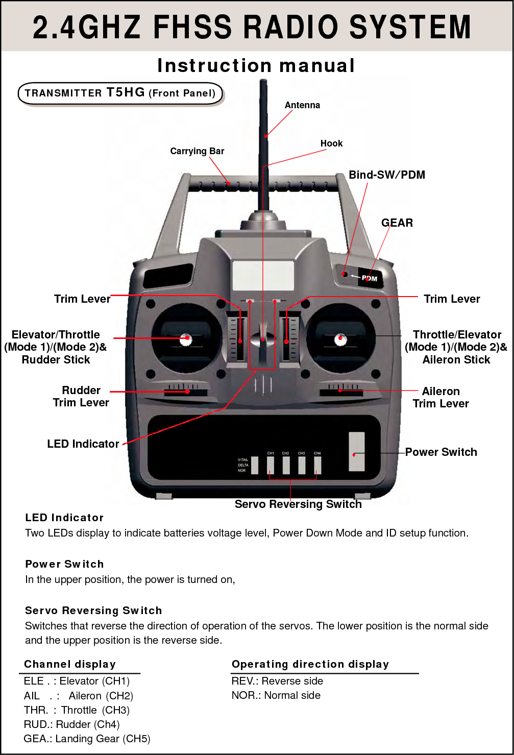
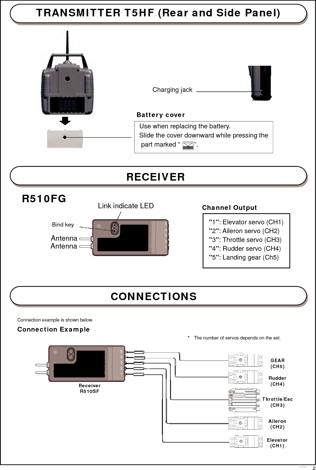
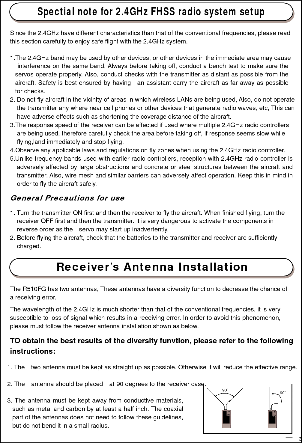
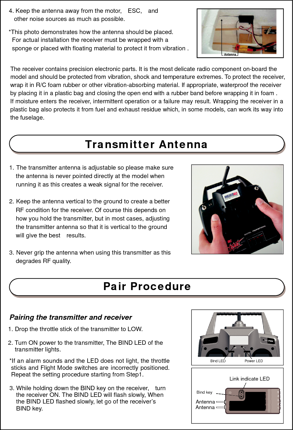
Sanwa Electronic Instrument Co ATX90150 2.4G RADIO SYSTEM User Manual

Sanwa Electronic Instrument Co Ltd 2.4G RADIO SYSTEM

User Manual

2.4GHZ FHSS RADIO SYSTEM Instruction manual TRANSMITTER T5HG (Front Panel) Antenna     Carrying Bar Hook    Bind-SW/PDM    GEAR       Trim Lever Trim Lever   Elevator/Throttle (Mode 1)/(Mode 2)& Rudder Stick   Rudder Trim Lever     Throttle/Elevator (Mode 1)/(Mode 2)& Aileron Stick   Aileron Trim Lever    LED Indicator       LED Indicator      Power Switch     Servo Reversing Switch Two LEDs display to indicate batteries voltage level, Power Down Mode and ID setup function.   Power Switch In the upper position, the power is turned on,   Servo Reversing Switch Switches that reverse the direction of operation of the servos. The lower position is the normal side and the upper position is the reverse side.  Channel display ELE . : Elevator (CH1) AIL  . :  Aileron (CH2) THR. : Throttle (CH3) RUD.: Rudder (Ch4) GEA.: Landing Gear (CH5) Operating direction display REV.: Reverse side NOR.: Normal side
 TRANSMITTER T5HF (Rear and Side Panel)           Charging jack    Battery cover Use when replacing the battery. Slide the cover downward while pressing the part marked “  ”.    RECEIVER   R510FG   Bind key  Antenna Antenna  Link indicate LED   5 4 3 2 1  Channel Output  "1": Elevator servo (CH1) "2": Aileron servo (CH2) "3": Throttle servo (CH3) "4": Rudder servo (CH4) "5": Landing gear (Ch5)      CONNECTIONS   Connection example is shown below. Connection Example    *  The number of servos depends on the set.  5 4 3 2 1  Receiver R510SF  GEAR (CH5)  Rudder (CH4)  Throttle/Esc (CH3)   Aileron (CH2)  Elevator (CH1)           2
 Spectial note for 2.4GHz FHSS radio system setup   Since the 2.4GHz have different characteristics than that of the conventional frequencies, please read this section carefully to enjoy safe flight with the 2.4GHz system.   1.The 2.4GHz band may be used by other devices, or other devices in the immediate area may cause interference on the same band, Always before taking off, conduct a bench test to make sure the servos operate properly. Also, conduct checks with the transmitter as distant as possible from the aircraft. Safety is best ensured by having   an assistant carry the aircraft as far away as possible for checks. 2. Do not fly aircraft in the vicinity of areas in which wireless LANs are being used, Also, do not operate the transmitter any where near cell phones or other devices that generate radio waves, etc, This can have adverse effects such as shortening the coverage distance of the aircraft. 3.The response speed of the receiver can be affected if used where multiple 2.4GHz radio controllers are being used, therefore carefully check the area before taking off, if response seems slow while flying,land immediately and stop flying. 4.Observe any applicable laws and regulations on fly zones when using the 2.4GHz radio controller. 5.Unlike frequency bands used with earlier radio controllers, reception with 2.4GHz radio controller is adversely affected by large obstructions and concrete or steel structures between the aircraft and transmitter. Also, wire mesh and similar barriers can adversely affect operation. Keep this in mind in order to fly the aircraft safely.  General Precautions for use  1. Turn the transmitter ON first and then the receiver to fly the aircraft. When finished flying, turn the receiver OFF first and then the transmitter. It is very dangerous to activate the components in reverse order as the    servo may start up inadvertently. 2. Before flying the aircraft, check that the batteries to the transmitter and receiver are sufficiently charged.   Receiver’s Antenna Installation   The R510FG has two antennas, These antennas have a diversity function to decrease the chance of a receiving error.  The wavelength of the 2.4GHz is much shorter than that of the conventional frequencies, it is very susceptible to loss of signal which results in a receiving error. In order to avoid this phenomenon, please must follow the receiver antenna installation shown as below.  .  TO obtain the best results of the diversity funvtion, please refer to the following instructions:  1. The    two antenna must be kept as straight up as possible. Otherwise it will reduce the effective range.   2. The    antenna should be placed    at 90 degrees to the receiver case.   3. The antenna must be kept away from conductive materials, such as metal and carbon by at least a half inch. The coaxial part of the antennas does not need to follow these guidelines, but do not bend it in a small radius.  900  900         3
24. Keep the antenna away from the motor,    ESC,    and other noise sources as much as possible.  *This photo demonstrates how the antenna should be placed. For actual installation the receiver must be wrapped with a sponge or placed with floating material to protect it from vibration .      Anlenna   The receiver contains precision electronic parts. It is the most delicate radio component on-board the model and should be protected from vibration, shock and temperature extremes. To protect the receiver, wrap it in R/C foam rubber or other vibration-absorbing material. If appropriate, waterproof the receiver by placing it in a plastic bag and closing the open end with a rubber band before wrapping it in foam . If moisture enters the receiver, intermittent operation or a failure may result. Wrapping the receiver in a plastic bag also protects it from fuel and exhaust residue which, in some models, can work its way into the fuselage. .    Transmitter Antenna   1. The transmitter antenna is adjustable so please make sure the antenna is never pointed directly at the model when running it as this creates a weak signal for the receiver.  2. Keep the antenna vertical to the ground to create a better RF condition for the receiver. Of course this depends on how you hold the transmitter, but in most cases, adjusting the transmitter antenna so that it is vertical to the ground will give the best    results.  3. Never grip the antenna when using this transmitter as this degrades RF quality.    Pair Procedure    Pairing the transmitter and receiver  1. Drop the throttle stick of the transmitter to LOW.  2. Turn ON power to the transmitter, The BIND LED of the transmitter lights.  *If an alarm sounds and the LED does not light, the throttle sticks and Flight Mode switches are incorrectly positioned. Repeat the setting procedure starting from Step1.  3. While holding down the BIND key on the receiver,    turn the receiver ON. The BIND LED will flash slowly, When the BIND LED flashed slowly, let go of the receiver’s BIND key.    Bind LED  Power LED   Link indicate LED  Bind key 5 4 Antenna 3 Antenna 1
 4. While the BIND LED on the receiver is flashing slowly, press the BIND Key on the transmitter. The BIND LED on the receiver starts flashing rapidly and soon after lights solidly. This indicates that pairing was successful.  *Unless the BIND key on the transmitter is pressed within 10 seconds, the BIND LED on the receiver will automatically time out and stop flashing. If this occurs, you simply need to repeat steps 3 and 4   Range check the radio   The controller has a Range Check Mode function. Which lowers the transmitter’s output level to check radio signal reception. Use this function to check radio signal reception on the ground, prior to flight. To check reception, put the controller in Range Check Mode, walk about 30 paces away from the aircraft, and check to make sure the servo moves without problem.  How to transmit to range check mode and check range  1. Drop the throttle sticks of the transmitter to the end of the low side. 2. While pressing the transmitter’s BIND key. Turn the transmitter power ON.   *If you hear a warning signal, correct the positions of the throttle sticks and Flight Mode switches and repeat the, the setting procedure starting with Step1.  3. The transmitters BIND LED will blink steadily. Continue holding the BIND button in for approximately 5 seconds until the LED goes out and then let go of the BIND button. IF the LED then resumed a steady blinking. The transition to Range Check Mode was successful. 4. Immediately turn the receiver ON, walk about 30 paces from the aircraft(approximately 90 feet)and, with help from another person, check to make sure the servos move without problem If there is a problem with servos movement, try moving while maintaining the same distance from the aircraft, and check again to make sure the servos movement, without problem. If there is still a problem with servos movement, check to make sure there are no problems with servos connector connections and so on. Do not fly the aircraft until you have solved the problem.  *Range Check Mode automatically turns off in about 3 minutes, and the system changes to Normal Mode. Be sure to check servos movement while checking that the transmitter’s LED is blinking. If the LED has changed to constantly lit status while checking servos movement, turn the transmitter power OFF. Repeat the process from step 1, then go into Range Check Mode.   *In this case. It is not necessary to turn the receiver OFF.   *Caution! Do not fly the aircraft while in Range Check Mode. You will be unable to control the aircraft once it has flown a certain distance.   Mode  Range Check Mode (Low transmission output) Normal Mode (Normal transmission output) Transmitter LED status  Steadily blinking  Constantly lit up
 Transmitter operation and Movement of Each Servo    Before making any adjustments, learn the operation of the transmitter and the movement of each servo.(In the following descriptions, the transmitter is assumed to be in the standby state.)     ELEVATOR OPERATION  When the elevator stick is pulled back, the tail elevator is raised and the tail of the plane is forced down, the air flow applied to the wings is changed, the lifting force is increased, the lifting force increased, and the plane climbs (UP operation). When the elevator stick is pushed forward, the elevator is lowered, the tail of the plane is forced up, the lifting force is decreased, and the plane dives (DOWN operation).   Elevator(CH1)   Down Down    Up Up  (Mode  1)  (Mode 2)     Down   Up     AILERON OPERATION When the aileron stick is moved to the right. The right aileron is raised and the left aileron is lowered. Relative to the direction of flight. And the plane turns to the right. When the aileron stick is moved to the left, the ailerons move in the opposite direction. To level the plant, the aileron stick must be moved   in the opposite direction. When the aileron stick is tilted and held, the plane will roll.  Aileron(CH2)      Left Right    (Viewed from the rear)  Left   Right       THROTTLE OPERATION When the throttle stick is pulled back, the engine throttle lever arm moves to the SLOW (low speed) side, When the throttle stick is pushed forward, the throttle lever arm moves to the HIGH (high speed) side. Throttle (CH3)   High High    Low Low  (Mode  1) (Mode  2)   High Increase throttle speed  Low Decrease throttle speed      THROTTLE OPERATION (Rudder) When the rudder stick is moved to the right, the rudder moves to the right and the nose points to the right, relative to the direction of flight. When the rudder stick is moved to the left, the rudder moves to the left and the nose points to the left and the direction of travel of the plane changes. Engine throttle lever moves  Left   Left Right Right           6
  WARNING    Connector Connection  Insert the receiver, servo, and battery connectors fully and firmly. If vibration, etc. causes a connector to work loose during running, the car may crash.    Receiver Vibration proofing/Waterproofing  Vibrationproof the receiver by wrapping it in sponge rubber or some such material. If the receiver may get wet, waterproof it by placing it in a plastic bag. If the receiver is subjected to strong vibration and shock, or gets wet, it may operate erroneously and cause a crash.   Servo Throw     Operate the servo horn over its full stroke and adjust so that the pushrod does not bind or is not too loose.  . Unreasonable force applied to the servo horn will adversely affect the servo and drain the battery quickly. .     Servo Installation  Install the servo to the servo mount, etc. through a rubber grommet. Also install the servo so that the servo case does not directly touch the servo mount or other parts of the chassis.      Receiver Antenna  Do not cut or bundle the receiver antenna. Also, do not bundle the antenna together with the servo lead wires. .   Cutting or bundling the receiver antenna will lower the receiver sensitivity and shorten the flight range and cause a crash.                    7
 Adjustments  The operating direction, and steering angle of each servo are adjusted.   CAUTION  The basic linkage and adjustments of the fuselage conform to the fuselage design drawings and kit    instruction manual. Be sure that the center of gravity is at the prescribed position.   Adjustment Procedure   Before making any adjustments, set all the SERVO REVERSER switches on the side of the transmitter to the lower (NOR) position. (Switch the switches with a small screwdriver, etc.) Turn on the transmitter and receiver power switch and make the following adjustments:   1.  Check the direction of operation of the servo. If a servo operates in the wrong direction, switch its SERVO REVERSER switch.(The direction of operation can be  changed without changing the linkage.) * Note that the direction of the aileron servo is easily mistaken. .   2. Check the aileron, elevator, and rudder neutral adjustment and left-right (up-down) throw. Check that when trimmed to the center, the servo horn is perpendicular to the servo and check the neutral position id the fuselage control surfaces (aileron, elevator, rudder, etc.). If the neutral position has changed, reset it by adjusting the length if the rod with the linkage rod adjuster. When the throw is unsuitable (different from steering anglespecified by the kit instruction manual), adjust it by changing the servo horn and each control surface horn rod.   3. Check the engine throttle (speed adjustment) linkage. Change the servo horn installation position and hole position so that the throttle is opened fully when the throttle is opened fully when the throttle stick is set to HIGH (forward) and is closed fully when  the throttle stick and throttle trim are srt for maximum slow (backward position and lower position, respectively).  4.  After all the linkages have been connected, recheck the operating direction, throw, etc. Before running adjust the car in accordance with the kit and engine instruction manuals.   5.  Fly the plane and trim each servo. .          8
Federal Communications Commission (FCC) Statement   This equipment has been tested. And it found to comply with the limits for a Class B digital device pursuant to Part 15 of the FCC Rules. These limits are designed to provide reasonable protection against harmful interference in a residential installation. This equipment generates and uses and radiates radio frequency energy and, if not installed and used in accordance with the instruction, may cause harmful interference to radio communications. However, there is no guarantee that interference will not occur in a particular installation. If this equipment does cause harmful interference to radio or television reception, which can be determined by turning the equipment off and on, the user is encouraged to try to correct the interference by one or more of the following measures:  - Reorient or relocate the receiving antenna. - Increase the separation between the equipment and receiver. - Connect the equipment into an outlet on a circuit different from that to which the receiver is connected - Consult the dealer or an experienced radio /TV technician for help.   Warning: A shielded-type power cord is required in order to meet FCC emission limits and also to prevent interference to the nearby radio and television reception. It is essential that only the supplied power cord be used.  1. This device complies with Part 15 of the FCC Rules. Operation is subject to the following two conditions: (1) This device may not cause harmful interference, and (2) This device must accept any interference received, including interference that may cause undesired operation.  2. Changes or modifications not expressly approved by the party responsible for compliance could void the user's authority to operate the equipment.   RF warning statement:  The device has been evaluated to meet general RF exposure requirement.   The device can be used in portable exposure condition without restriction.                                   9

Navigation menu