Sanwa Electronic Instrument Co ATX90354 Remote Control Transmitter User Manual RD8AT 002 003 eps
Sanwa Electronic Instrument Co Ltd Remote Control Transmitter RD8AT 002 003 eps
Contents
- 1. User Manual Part I
- 2. User Manual Part II
User Manual Part I

32
Thisequipmenthasbeentestedinaccordancewiththe
requirementscontainedintheappropriateCommission
regulations.Tothebestofourknowledge,thesetestswere
performedusingmeasurementproceduresconsistentwith
industryorCommissionstandardsanddemonstratethatthe
equipmentcomplieswiththeappropriatestandards.Each
unitmanufactured,importedormarketed,asdefinedin
theCommission,
sregulations,willconformtothesample(s)
testedwithinthevariationsthatcanbeexpecteddueto
qualityproductionandtestingonastatisticalbasis.
Wefurthercertifythatthenecessarymeasurementswere
madebyKansaiElectronicIndustryDevelopmentCenter,
IkomaEmissionMeasurementStation,10830,Takayama-
Cho,Ikoma-City,Nara,630-01Japan.
SECTIONIINTRODUCTION
RDS8000RadioControlSystem
2.4GHzsystem
RDS8000Transmitter/ReceiverSpecifications
InitialPreparation
RDS8000TransmitterFeatures
AirborneSystemConnections
NiCdBatteryCharging
AirborneComponents
Connectors
AudioLowVoltageAlarm
TransmitterBatteryRemoval
ThrottleHighWarning
TransmitterStickLengthAdjustment
TransmitterStickTensionAdjustment
TrainerSystem
UsingtheRDS8000Micro-Processor
Failsafe
SECTIONIIAIRPLANE
ImplementationofControlFunction
ServoReversing
ControlCentering
DataReset
ModelSelect
StopWatch
IntegralTimer
NamingYourModel
Exponential
DataCopy
SwitchReverse
Click
ThrottleCut
RDS8000Transmitter-Aircraft
AircraftMenuStructure
ProgrammingforAircraft(ModelType)
DualRate
EndPointAdjustments
LandingGearEndPoints
TrimMemory
3-PositionFlapSwitch
Flaperons
Alarms
Delta(Elevons)
AilerontoRudderMix
V-Tail(RuddertoElevatorMix)
ThrottletoElevatorMix
CompensationMixers(C-Mix)
TABLEOFCONTENTS
5
5
5
AcademyofModelAeronautics6
FCCComplianceStatement6
6
7
TransmitterFeaturesandfunctions8
9
9
10
10
10
11
11
11
12
15
Precautionsforuse:
Transmitter/Receiver
13
Generalprecautionsforuse13
Precautionsonusingthe2.4GHzband
13
16
18
RangeCheckMode18
Pairing(Binding)16
BarGraphVoltageIndicator
AEROFeaturesDescription
19
20
HELIFeaturesDescription21
22
22
23
24
25
26
27
28
29
32
34
35
36
37
38
39
41
42
43
44
44
45
47
48
49
50
51
52
Page#
Elev-FlapMixing
Rud-AileronMixing
Rud-ElevatorMixing
Flap-ElevatorMixing
Spoileron
AileronDifferential
LandingDifferential
CrowLeftAileron
CrowRightAileron
OptionMenuScreen
TrimStep
BasicMenu
DualElevatorMixing
54
55
55
56
56
57
58
59
59
60
61
61
62
AUX-1andAUX-262

54
SECTIONIIIHELICOPTER
RDS8000Transmitter-Helicopter
AirborneSystemConnections
HelicopterMenuStructure
ProgrammingforHelicopter(Type)
PitchCurves
ThrottleCurves
RevolutionMixing
GyroAdjustment
TrimMemory
Exponential
DualRate
DynamicTrimMemory(DTM)
SwashPlateType(CCPM)
ChangingFlightMode1and2SwitchLocations
ImplementationofControlFunction
ServoReversing
ControlCentering
DataReset
ModelSelection
StopWatch
IntegralTimer
NamingYourModel
Exponential
DataCopy
SwitchReverse
Click
ThrottleCut
EndPointAdjustment
TrimMemory
Alarms(ThrottleHighandFlightModeOnly)
CompensationMixers(C-Mix)
OptionMenu
TrimStep
BasicMenu
APPENDIXI
RDS8000AircraftandHelicopterSetuppages
63
9
62
65
67
70
72
73
74
29
74
75
76
77
22
22
23
24
25
26
27
28
29
32
34
35
36
42
44
47
52
60
61
61
Page#
78
RDS8000TransmitterSpecifications:
TransmitterType:
Dimensions:
Weight:
PowerOutput:
Frequencies:
PowerSupply:
CurrentDrain:
TemperatureRange:
PulseWidth:
ModelMemory:
RDS8000ReceiverSpecifications:
8Channel,DualStickwithproprietaryMicroprocessor
W:7.5”XH:8.0”XD:2.5”
1lb.11oz
90mWatts
2.4GHz
9.6Volt,NiCd
180MA
0to160degreesF
1.5ms(nominal)
10
ReceiverType:
Dimensions:
Weight:
92824Z8Channel,FHSS,“Z”Connectors
L:1.85”,W:1.08”,H:0.61”
0.53oz
FourCell,4.8Volt
RDS8000RADIOCONTROLSYSTEM
ThankyouforselectingtheAirtronicsRDS8000RadioSystem.IndesigningtheRDS8000wehave
madeeveryefforttoprovideyouwitharadiothatwillallowyoutoextractthemaximumperformance
fromyourpoweredaircraft,sailplane,orhelicopter,whileatthesametimesimplifyingthetaskof
settingupandadjustingyourmodel.Theseinstructionsarewritteningreatdetailtohelpyou
understandalloftheRDS8000capabilities.BecauseofthemanyfeaturesoftheRDS8000,
thismanualisquitelong.Don’tbeintimidated!Toactuallyusethesystem,youmayonlyneedto
readtheINTRODUCTIONsection,theCommonFunctionssection,andstudythesectionthatapplies
toyourtypeofaircraft.Eachtypeofaircraft,i.e.,fixedwingandhelicopterhasitsownself-contained
sectiondescribingeachapplicablefeatureanditsimplementation.However,helicopterflyersmay
finditadvantageoustoreadallsectionsofthemanualtobecomemoreacquaintedwiththeoperation
oftheRDS8000unit.Notethatthelabelsforfixedwingswitchfunctionsareinredlettersand
helicopterswitchfunctionsareinBlueletters.
Again,weappreciateyourselectionofanAirtronicsRadioControlSystemandwishyoumanyhours
offlyingenjoyment.
SECTIONI
2.4GHzsystem
Thisradiocontrolleroperatesinthe2.4GHzband.The2.4GHzconnectionisdeterminedbythe
transmitterandreceiverpair,therefore,unlikeordinarycrystalsystems,theaircraftcanbeflown
withoutfrequencycontrol.
Also,aseparate2.4GHzreceivercanbepurchasedandpairedwiththeincluded2.4GHz
transmitterthroughapairingoperation.
ReceiverPowerSupply:

76
SECTIONI
ACADEMYOFMODELAERONAUTICS
5161EastMemorialDrive
Muncie,Indiana47302
TheAcademyofModelAeronautics(AMA)isanationalorganizationrepresentingmodelersintheUnited
States.Weurgeyoutoexaminethebenefitsofmembership,includingliabilityprotectionintheeventofcertain
injuries.TheAcademyhasadoptedsimpleandsaneruleswhichareespeciallypertinentforradiocontrolled
flightastheOFFICIALAMANATIONALMODELAIRCRAFTSAFETYCODE,whichwehavepartiallyreprinted
below:
Iwillnotflymymodelaircraftinsanctionedevents,airshowsormodelflyingdemonstrationsuntilithasbeen
proventobeairworthybyhavingbeenpreviously,successfullyflighttested.
Iwillnotflymymodelhigherthanapproximately400feetwithin3milesofanairportwithoutnotifyingthe
airportoperator.Iwillgivetheright-of-wayandavoidflyingintheproximityoffull-scaleaircraft.Where
necessary,anobservershallbeutilizedtosuperviseflyingtoavoidhavingmodelsflyintheproximityof
full-scaleaircraft.Whereestablished,IwillabidebythesafetyrulesfortheflyingsiteIuse,andIwillnotwillfully
anddeliberatelyflymymodelsinacareless,recklessand/ordangerousmanner.
Iwillhavecompletedasuccessfulradioequipmentgroundrangecheckbeforethefirstflightofanewor
repairedmodel.
IwillnotflymymodelaircraftinthepresenceofspectatorsuntilIbecomeaqualifiedflyer,unlessassistedby
andexperiencedhelper.
Iwillperformmyinitialturnaftertakeoffawayfromthepitorspectatorareas,unlessbeyondmycontrol.
INITIALPREPARATION
PACKAGING:
ThepackagingofyourAirtronicsRDS8000RadioControlSystemhasbeenespeciallydesignedforthesafe
transportationandstorageoftheradio’scomponents.Afterunpackingyourradio,DONOTDISCARDTHE
PACKAGINGMATERIALS!Youshouldsetthepackagingasideforuseifyoueverneedtosendyourradioin
forservice,ortostoreyourradioincaseyoudonotplantouseitforanextendedperiodoftime.
RDS8000TRANSMITTERSFEATURES
ProgramFeaturesforalltypesofmodels(BASICturnedON)
10-ModelMemory
StopWatch
DigitalTrims
ServoReversingonallchannels
DualRateonElevatorandAileronchannels
(PlusRudderonHelicopter)
LargeLiquidCrystalDisplay(LCD)
End-PointAdjustmentonallchannels
AircraftAdvancedFeatures(BASICturnedOFF)
AllofthefeatureslistedundertheprogramwiththeBASICturnedONarealsoincludedinthisAdvanced
Featuressection.
Exponential
AileronDifferential
TrimMemory
LandingDifferential
TrimAuthority(STEP)fordigitaltrims
Crow
ModelNaming(3Letters)
DualRateAlarm
MenuOptions
FlaptoElevatorMix
LowBatteryAlarm
ThrottletoElevatorMix
IntegralSystemTimer
RuddertoAileronMix
DataCopy
AilerontoRudderMix
FlaperonMix
RuddertoElevatorMix
SpoileronMix
ElevatortoFlapMix
ElevonMix
SwitchReversing
V-TailMix
2CompensationMixers
ThrottleCut
"Click"AudioTones DeltaMix
DualElevatorMix
HelicopterFeatures(BASIC) HelicopterFeatures(Advanced)
includesBasic
StopWatch
Exponential
ServoReversing
DualRateElev,AilandRud ThrottleCut
ServoCentering ModelNaming(3Letters)
EndPointAdjustment 2CompensationMixers
ThrottleCurve(5Point)inallFlightmodes IntegralSystemTimer
RevoMix(3Point)inallFlightModes TrimStep
4FlightModes SwitchReversing
GyroSensitivityAdjustmentinallFlightModes DataCopy
PitchCurve(5Point)inallFlightModes
ModelSelect
"Click"AudioTones
ModelType
DataReset
DynamicTrimMemory
BasicON
SwashPlateType
BasicOFF
OptionMenu
ModelTypeselection
CenterAdjustmentonallchannels
DataReset
LCDTransmitterVoltageMeter
High-CapacityTransmitterNiCd
Batteries
AdjustableStickTensionandLength
LowBattery,HighThrottleandPowerAlarms
FCCCOMPLIANCESTATEMENT
ThisequipmenthasbeentestedandfoundtocomplywiththelimitsforaClassBdigitaldevice,pursuantto
Part15oftheFCCRules.
Theselimitsaredesignedtoprovidereasonableprotectionagainstharmfulinterferenceinaresidential
installation.Thisequipmentgenerates,usesandcanradiateradiofrequencyenergyand,ifnotinstalledand
usedinaccordancewiththeinstructions,maycauseharmfulinterferencetoradiocommunications.However,
thereisnoguaranteethatinterferencewillnotoccurinaparticularinstallation.
Ifthisequipmentdoescauseharmfulinterferencetoradioortelevisionreception,whichcanbedeterminedby
turningtheequipmentoffandon,theuserisencouragedtotrytocorrecttheinterferencebyoneormoreofthe
followingmeasures:
Reorientorrelocatethereceivingantenna.
Increasetheseparationbetweentheequipmentandreceiver.
Connecttheequipmentintoanoutletonacircuitdifferentfromthattowhichthereceiverisconnected.
Consultthedealeroranexperiencedtechnicianforhelp.
ThisdevicecomplieswithPart15oftheFCCRulesandwithRSS-210ofIndustryCanada.Operationissubject
tothefollowingtwoconditions:
1.thisdevicemynotcauseharmfulinterference,and
2.thisdevicemustacceptanyinterferencereceived,includinginterferencethatmaycauseundesiredoperation.
Warning: Changes or modifications not expressly approved by the party responsible for compliance could void
the user's authority to operate the equipment.
RFExposureStatement
ThistransmitterhasbeentestedandmeetstheFCCRFexposureguidelineswhenusedwiththeAirtronics
accessoriessuppliedordesignatedforthisproduct,andprovidedatleast20cmseparationbetweenthe
antennaandtheuser'sbodyismaintained.UseofotheraccessoriesmaynotensurecompliancewithFCCRF
exposureguidelines.
TheRDS8000computerradiocontrolsystemisdesignedfortheusebypowermodel,sailplane,andhelicopter
pilotswhodemandaqualityproduct.TheRDS8000ispackedwithallofthecapabilitiesthatthebeginneras
wellasthemoreadvancedmodelersdemandforallthreetypesofflying.
Ithasthefeaturesavailabletogetthemostoutofanytypeofmodel.
98
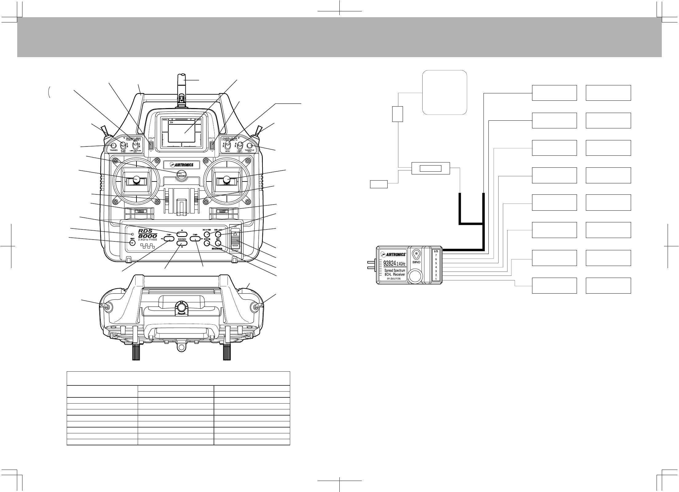
TheabovediagramshowshowtoconnectthecomponentsofyourRDS8000systemtogether.Atthispointyour
objectiveistogetthesystemoperatingonyourworkbench.Onceconnectedyoumustthenrefertothe
correspondingdiagramforyoursystem,i.e.,eitherAEROorHELIshowingthetransmittercontrolstickfunction.
NiCdBATTERYCHARGINGINFORMATION:
InordertoprotectthechargingcircuitinyourRDS8000transmitter,adiodehasbeeninstalledtoprotectitfrom
someofthehighdischargerate“cycler's”onthemarket.Werecommendthatyouchargethetransmitter
battery(whileinstalled)withthesuppliedATXcharger,Part#95033Z.
Shouldyouwishto“cycle”ordischargethetransmitterbattery,youmustfirstremoveitfromthetransmitter.
Thisallowsyoutobypasstheprotectivediode.
ThefollowingtwoAirtronicsserviceitemswillallowyouto“cycle”yourRDS8000transmitterbattery.Seeyour
localdealerfortheseitems.
(1)#99704TransmitterChargingPlugwithCableforusewithyourcyclingdevice(blackwirew/whitetraceris
positive.
(1)#97051TransmitterBatteryCyclingAdapterCable.
AboveitemswillalsoworkwithAirtronicsQuasar,Radiant,Vanguard,VGSeriesandallRDSeriestransmitter
batteries.
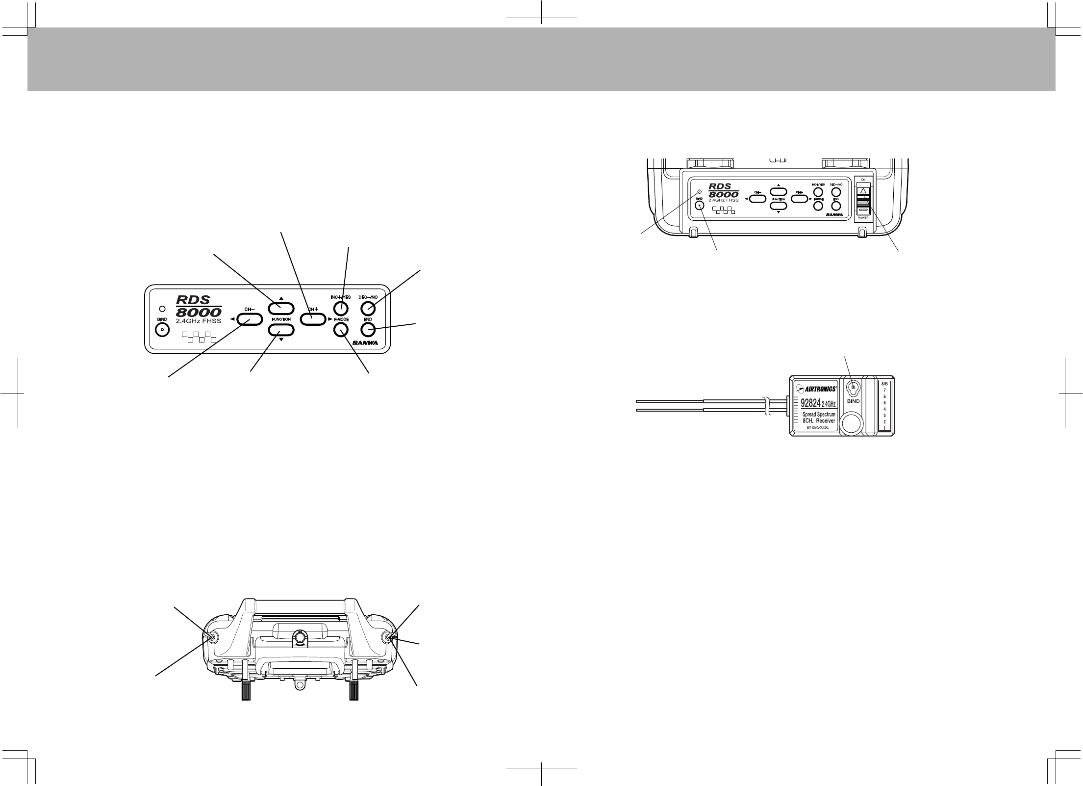
AIRBORNESYSTEMCONNECTIONSTRANSMITTERFEATURESANDFUNCTIONS
NiCd
Battery
SwitchHarness
Charger
Connector
92824ZReceiver
AERO HELI
Flap
RetractGear
Rudder
Throttle
Aileron
Elevator
CollectivePitch
Gyro
Rudder
(TailRotor)
Throttle
Aileron
(L/RCyclic)
Elevator
(F/ACyclic)
AUX2AUX2
AUX1AUX1
97020ZY-Harness
orconnecttheSwitch
Harnessdirectlyinto
theReceiver
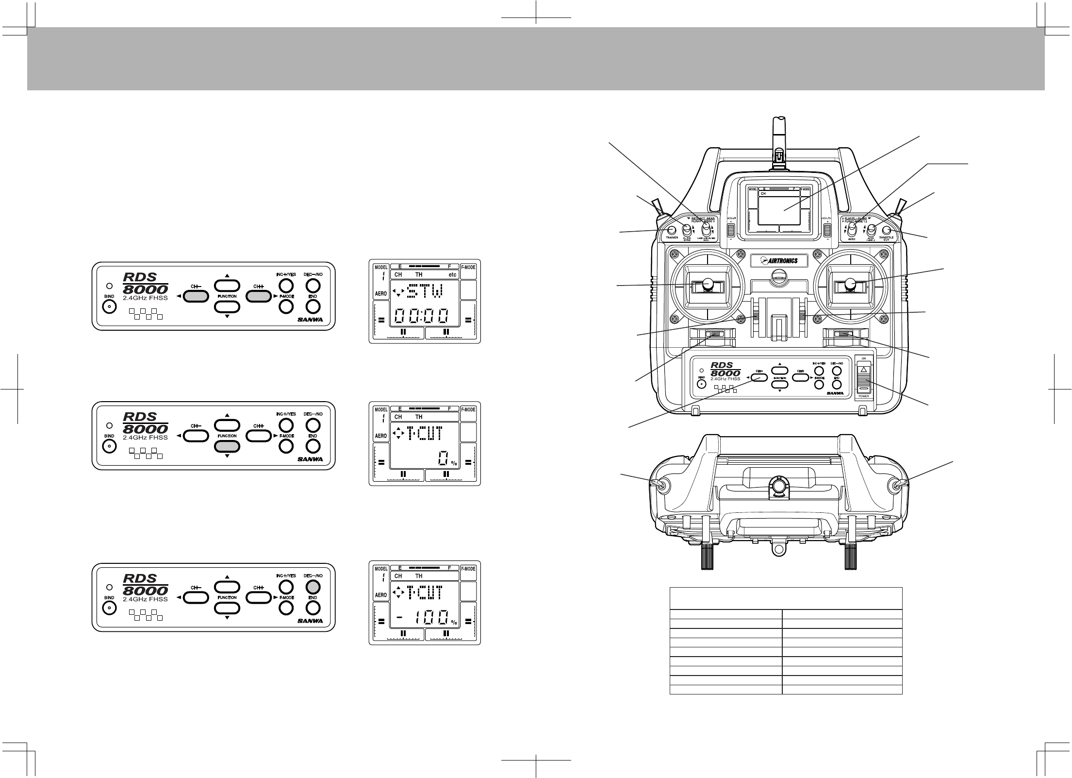
RDS8000Transmitter-AIRCRAFT/HELICOPTER
C-MIX1,2
AUX-1
DigitalHoverPitchINC/DEC
AUX-1
CarryingHandle AntennaHELI:
HELI:
AERO
AERO:
AERO:
ElevatorDualRateSwitch
HELI:Gyro
TrainerSwitch
NeckStrapHook
Throttle(U/D)
Rudder(L/R)
ThrottleDigitalTrim
RudderDigitalTrim
BindLED
UpMoveKey
BindKey
ChannelSelectorLeftMoveKey DownMoveKey ChannelSelectorRightMoveKey
RetractSwitch
HELI
:
FlightMode3
(SeePage77to
changeF.M.switch
locations)
LiquidCrystalDisplay
AUX-2
AERO:
AileronDualRateSwitch
HELI:C-Mix1,2
HELI:
SelectFlightModekey
AERO:
FlapSwitch
HELI:
FlightModeN,1,2
(SeePage77to
changeF.M.switch
locations)
ThrottleCutSwitch
MainPowerSwitch
ChargingJack
TrainerJack
IncreaseValueor
indicateYESkey
DecreaseValueor
indicateNOkey
EndKey
ElevatorDigitalTrim
AileronDigitalTrim
Elevator(U/D)
Aileron(L/R)
HELI:DigitalHoverThrottleINC/DEC
92824ZReceiverChannelAssignments
1
2
3
4
5
6
7
8/B
PluginServoFor:
Elevator
Aileron
Throttle
Rudder
Gear
Flapor2ndAileronServo
AUX1
AUX2/Battery
AERO
ReceiverSlotNumber HELI
PluginServoFor:
Elevator(F/A)Cyclic
Aileron(L/R)Cyclic
Throttle
Rudder(TailRotor)
Gyro
CollectivePitch
AUX1
AUX2/Battery
10 11
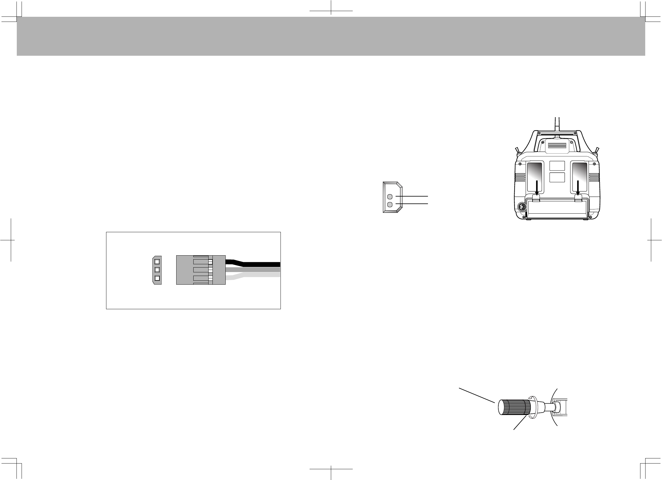
TRANSMITTERBATTERYREMOVAL
CAUTION:
ObservethecorrectpolaritywhenpluggingintheNiCdbatterypack.
Ifincorrect,damagetothetransmitterwilloccur!
Part(A)LoosenEndCapFirst
Part(B)AdjustStickLengthbyturninghere
Negative
Positive
TheNiCdbatteryinyourRDS8000transmittercaneasilyberemovedandreplacedwithafullychargedpack
toextendoperatingtime.
AdditionalpacksaresoldseparatelyasanaccessoryitemundertheAirtronicspartnumber95010(600Mah),
95090(700Mah)or95052(1100Mah)batterypacks.
Toremovethepack,pushdownonthetwoearsofthebatterydoorlocatedontherearofthetransmitter.
ThedoorcanthenberemovedandtheNiCdbatterypackcannowberemovedandunplugged.Reversethe
proceduretoinstallanewpack.
THROTTLEHIGHWARNING
TheRDS8000hasabuiltinwarningfeaturethatwillnotallowyoutousethetransmitterifthethrottlestickisnot
inthelowestpositionwhenyouturnonthetransmitter.Ifthethrottlestickisnotinthelowposition,whenyou
turniton,youwillhearacontinuousbeepingsoundandthedisplaywillreadTH-HI!Pullthethrottlestickdown
tothefulllowposition.Thenormalmenuwillthenbedisplayedandyoucanoperateand/orprogramthe
transmitter.
TRANSMITTERSTICKLENGTHADJUSTMENT
ThesticksinyourRDS8000transmitterareadjustableinlengthandspringtensiontoallowyoutotailortheirfeel
toyourpersonalpreference.Toadjuststicklength,holdPartBwithyourfingersandunscrewPartA
counterclockwisetoloosenthetwopieces.NowscrewPartAinorouttothedesiredpositionandlockitin
placebyscrewingPartBagainstit.ItisbesttoleaveatleastfourthreadsinsidePartAwhenscrewedouttoits
longestlengthforthebestmechanicalsecurity.Donotovertightenwhenyouscrewthetwopartstogether.
AIRBORNECOMPONENTS
Whileyoursystem'sbatteriesarecharging,youcanfamiliarizeyourselfwiththeairborneportionofyourradio.
Theairborneportionoftheradioreferstoanycomponentswhicharemountedinyourplaneorhelicopterand
carriedaloftwhenyoufly.Theairbornecomponentsconsistofthereceiver,whichreceivesthesignalsfromthe
transmitter,decodesthem,andrelaysthecommandstotheservos;theservoswhicharesimplyelectronically
controlledmotorsusedtomovethesurfacesoftheplane;theNiCdbatterypackwhichprovidespowerforthe
receiverandservostooperate;andtheswitchharnesswhichallowsyoutoturntheairbornepackageonandoff.
CONNECTORS
YourRDS8000unitisequippedwiththeneweruniversalAIRTRONICS“Z”connectorswhicharecolorcodedblue,
andareelectricallycompatiblewiththereceiversofotherradiocontrolsystemmanufacturers.Theconnectors
areruggedbutshouldbehandledwithcare.Notethattheseconnectorsarenotcompatiblewitholder
AIRTRONICSR/CequipmentunlessAdapterp/n99399Zisused!
AUDIOLOWVOLTAGEALARM
YourRDS8000transmitterisequippedwithanAudioAlarmwhichwillsoundwheneverthetransmitterbatteries
dropbelow9.5voltsduringtransmitteroperation.Ifthealarmsoundswhileyouareflying,landimmediately
anddon’toperatethetransmitteruntilithasbeenchargedfor12hours.Thetransmittershouldnormally
operate120to150minutesbeforethealarmsounds.Ifthealarmsoundsevenafterthebatterieshavebeenon
chargefortherequiredtimeitindicatesthatthereisaproblemwitheitherthebatterypackorthetransmitter,
andyoushouldcontactAIRTRONICSaboutservice.
“Z”CONNECTOR
(-)Negative
(+)Positive
Signal
12 13
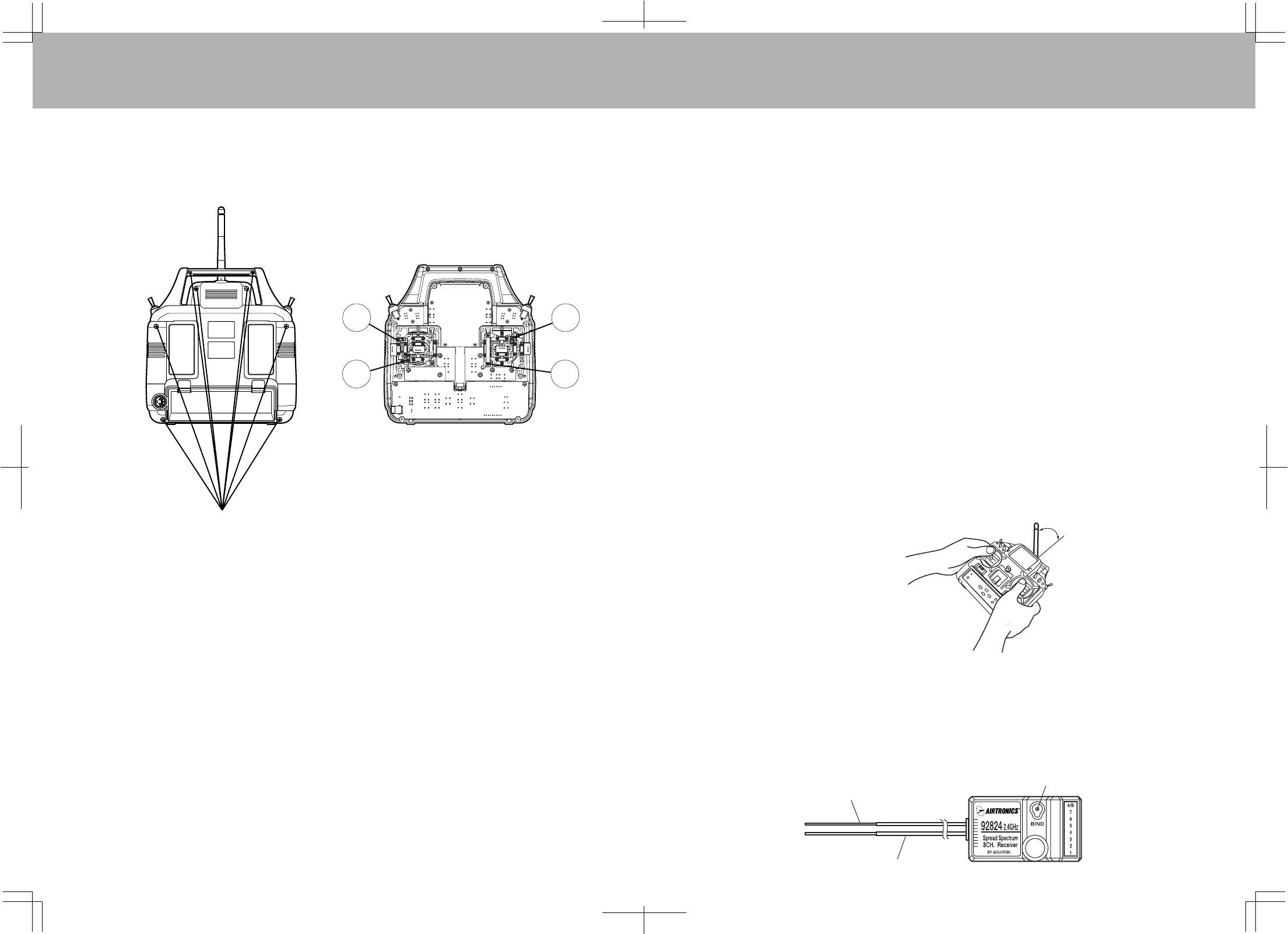
Antenna coaxial cable
Bind key & Bind LED
1
2
Screw Locations
3
4
Precautions on using the 2.4 GHz band
The 2.4 GHz band may be used by other devices, or other devices in the immediate area may cause
interference on the same band. Always before takeoff, conduct a bench test to make sure the servos operate
properly. Also, conduct checks with the transmitter as distant as possible from the aircraft. Safety is best
ensured by having an assistant carry the aircraft as far away as possible for checks.
Do not fly aircraft in the vicinity of areas in which wireless LANs are being used. Also, do not operate the
transmitter anywhere near cell phones or other devices that generate radio waves, etc. This can have
adverse effects such as shortening the coverage distance of the aircraft.
The response speed of the receiver can be affected if used where multiple 2.4 GHz radio controllers are
being used, therefore carefully check the area before takeoff. Also, if response seems slow while flying,
land immediately and stop flying.
Observe any applicable laws and regulations on fly zones when using the 2.4 GHz radio controller.
Unlike frequency bands used with earlier radio controllers, reception with this 2.4 GHz radio controller is
adversely affected by large obstructions and concrete or steel structures between the aircraft and
transmitter. Also, wire mesh and similar barriers can adversely affect operation. Keep this in mind in order
to fly the aircraft safely.
General precautions for use
Turn the transmitter ON first and then the receiver to fly the aircraft. When finished flying, turn the receiver
OFF first and then the transmitter. It is very dangerous to activate the components in reverse order as the
servo may start up inadvertently.
Before flying the aircraft, check that the batteries to the transmitter and receiver are sufficiently charged.
Precautions for use: Transmitter
TRANSMITTER STICK TENSION ADJUSTMENT
To adjust the spring tension of the transmitter sticks you need to remove the back of the transmitter case. First
remove the antenna and the NiCd battery pack from the transmitter. Now remove the eight screws that hold the
case back in place, four in the main case, two in the LCD back cover and two on the handle.
Once the screws are removed swing the back of the case away from the transmitter being careful of the trainer
plug wiring.
There are four locations for the stick tension adjustment screws installed because the stick controlling the
throttle is ratcheted and has no tension adjustment. The #1 and #3 screws adjust the tension for the vertical
motion of each stick. The #2 and #4 screws adjust the tension for the horizontal motion of each stick. To make
the tension adjustment use a small phillips type screwdriver to turn the adjustment screws. Turning the screw
clockwise will increase the stick tension, turning it counterclockwise will decrease the tension. Once you have
completed your stick adjustments, replace the case back and install the NiCd battery pack and antenna. Be
careful to line the battery charging port pins when replacing the back cover.
Never touch the transmitter antenna while flying the aircraft. Doing so may cause loss of transmitter output,
making it impossible to operate the aircraft.
Keep the antenna of the transmitter perpendicular to the ground as best possible.
1.
Precautions for use: Receiver handling and mounting on aircraft
The receiver has 2 antenna wires. The thin section at the tip is the antenna reception wire, therefore mount the
antenna to the aircraft without bending the reception wire. Reception performance decreases if the reception
wire is bent.
1.
The transmitter's antenna is delicate. Handle with care.
Do not press the BIND key while flying the aircraft. The radio signal is interrupted while the BIND and trainer
keys are pressed. It may also require time to restore the signal after releasing the keys, which can be
dangerous.
2.
3.
1.
2.
3.
4.
5.
1.
2.
WARNING:
Any other modifications made to the transmitter other than adjusting stick tension will void any and all
warranties covered by Airtronics Inc.
Keep perpendicular to
ground.
Antenna reception wire
1514
NOTE:
Bothtransmittersmustbeprogrammedidenticallyforthetrainersystemtofunctionproperly.Allservosmust
operateinthesamedirection,centering,endpoints,andothersettingssuchastypeofModulationmustbe
identical.
TrainerSwitch
(SpringLoaded)
MasterTransmitter TrainerTransmitter
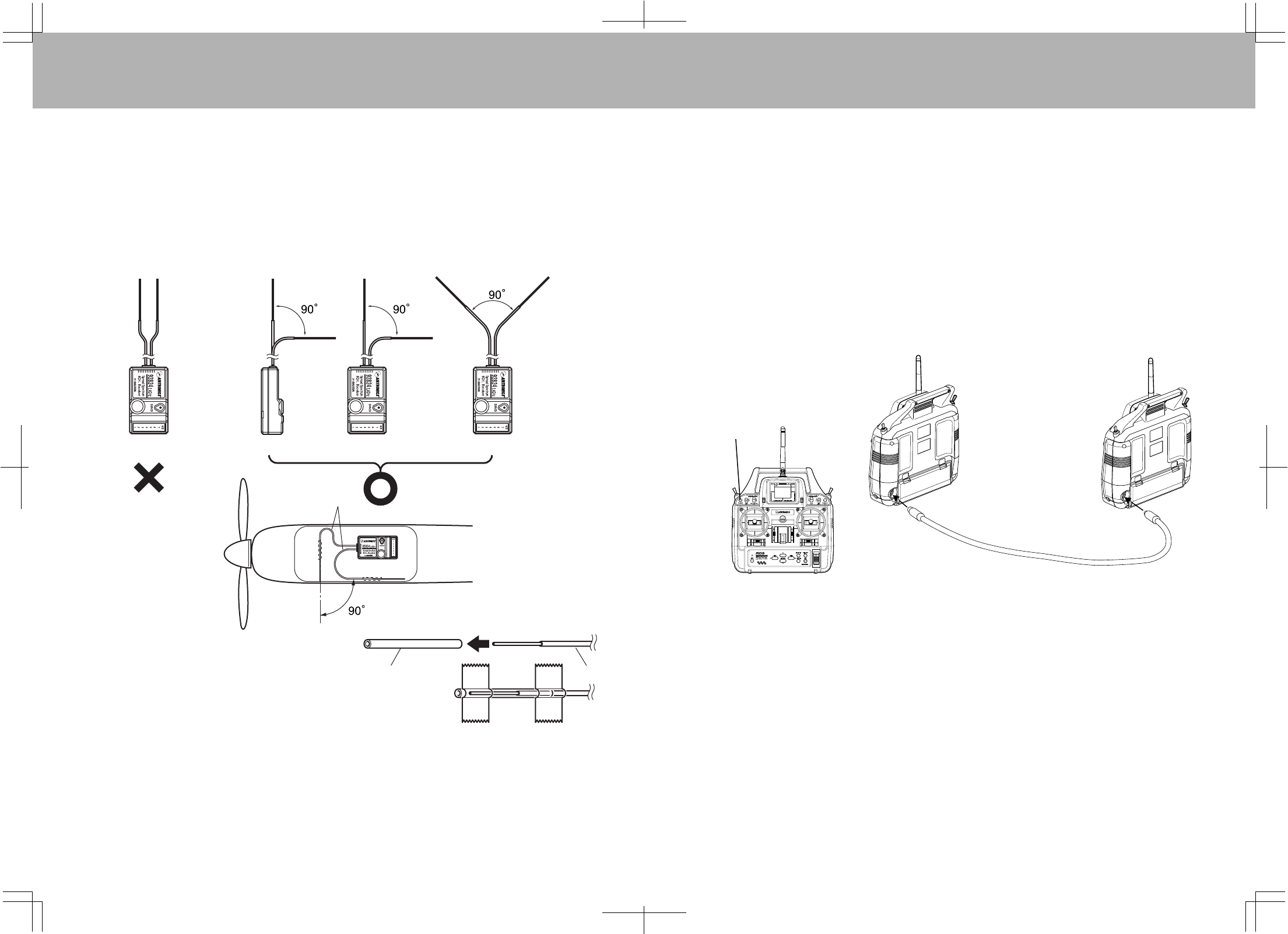
Thereceiverantennawiresaredelicate,thereforehandlewithcare.Inparticular,donotpullonthemwith
forceorpushthemintothecase.
Donotcutorextendthereceiverantennawires.
Thethickportionofthereceiver'santennaisthecoaxialcable.Donotusetheunitwiththispartoftheantenna
bentacutely.Inaddition,donotrepeatedlybendthisparttoanacuteanglebecausethiscancausetheantenna
coretobreak.Whenmountingontheaircraft,benditasgentlyaspossibleforusage.
Mountthereceiverantennawiresonawoodorplasticnonconductivepartoftheaircraftandbendsothat
thetwowiresare90¡ apart.
∗Thisisextremelyimportantinensuringthattheaircraftreceivescontrolsignalsnomatterwhatitsposture,
attitudeorheading.
7.
8.
9.
10.
Protecttheantennareceptionwireswithaplasticpipe
(i.e.,antennapipeforcarradiocontroller,etc.)when
mountingthereceiverontheaircraft.
Preventtheantennareceptionwiresfromcontactingconductivepartswhenmountingthereceiverontheaircraft.
Gliderbodiesandhelicopterframesmaycontainconductiveparts,thereforecheckcarefully.
Ifmountingthereceiveronanaircraftmadeofconductivematerialandtheantennareceptionwiresare
surroundedbyconductivematerials,mountthereceiversothatthereceptionwiresextendoutsideoftheaircraft
body.Receptioncanbeblockedifthereceptionwiresareshielded.
MountthereceiverandantennasothattheyareasafedistancefromESCs(ElectronicSpeedController),
motorsandengines.Allsuchcomponentsgeneratenoiseandmayadverselyaffectreception.
Locationofthereceiverandantennareceptionwiresmayalterperformance.Ifthishappens,tryrepositioning
thereceiverandantennareceptionwires,ensuringtheaforementionedmountingrequirementsaresatisfied.
Oncehavingdoneso,checkthattheaircraftandservosoperateproperlybeforetakingoff.
6.
2.
3.
4.
5.
Receiver Receiver Receiver Receiver
Antenna
Plasticpipe Antenna
Anchorinplacewithepoxy
ortapetopreventloss.
TRAINERSYSTEM
TheTrainersystemintheRDS8000transmitterallowsyoutoconnectanytwoAirtronicsRDseriestransmitters
togetherforthepurposeoftraininganewpilot.YoucanalsoconnecttheRDS8000toeitherVG400,VG600,
RD6000,RD8000
RadiantorVanguardPPMunit.TheTrainercordtouseistheATXPart#97100.TheRDS8000
isNOTcompatiblewithStylus,Infinity660orQuasarunits.
Inactualuse,oneofthetwotransmitterswillserveastheMasterandthesecondtransmitterwillserveas
theTrainer.TheMastertransmitterisheldbytheinstructingpilot,ANDISTHETRANSMITTERTHATMUST
MATCHTHERECEIVERFREQUENCYINSTALLEDINTHEMODEL!Thetrainertransmitterisheldbythe
learningpilot,anddoesnotneedtobeonthesamefrequencyasthemodel.ThefrequencyoftheTrainer
transmitterisunimportantbecausetheswitchofthetrainertransmitterisNOTturnedonduringinstructional
flying.Normallyduringtraining,theinstructortakesthemodeloffandfliesittoareasonablealtitude.
WhiletheMaster/TrainerswitchontheInstructor'stransmitterisleftinitsOFFposition,theMastertransmitter
willhavefullcontrolofthemodel.Whentheinstructorisreadytobegintraining,hepressesandholdsthe
spring-loadedswitchonhistransmitterwhichtransferscontroltothestudent.
AslongastheinstructorholdshisTrainerswitchintheONposition,themodelwillrespondtothecommands
oftheTrainertransmittersticksallowingthestudenttoflythemodel.Itisnotnecessaryforthestudenttohold
thetrainerswitchontheTrainertransmitter.
Whentheinstructorceasestraining,orifhefeelsthatthestudentisinasituationthatendangersthemodel,
theinstructorcanreleasethespring-loadedswitchandcontrolofthemodelwillimmediatelyreturntothe
Mastertransmitter.TousetheTrainersystem,youmustplugtheappropriateTrainercableintothebackof
boththeMasterandtheTrainertransmitters.TurnontheMastertransmitterandtheModel.Thecablewill
energizetheencodersectionoftheTrainertransmitter.OnceyouhaveverifiedthatboththeMasterandthe
Trainertransmitterswillcontrolthemodelwiththespring-loadedswitchintheappropriatepositionyouare
readytostarttraining.
Tocheckthis,pressandreleasethetrainerbuttononthemasterradio,whileobservingthecontrolsurfaces
andthrottleposition.Makesurenothingwiggles.Adjustservodirectionandtrimuntilnothingwiggleswhenthe
buttonispressedandreleased.Withthesticksatfulldeflection(fullleftaileron,forinstance)alsopressand
releasethetrainerbuttontoensurethatnoneofthesurfacesorthrottlewiggles.
ON
POWER
HOV—THHOV—PI
1716
TurnONpowertothetransmitter.TheBINDLEDofthetransmitterlights.
∗IfanalarmsoundsandtheLEDdoesnotlight,thethrottlesticksandFlightModeswitchesare
incorrectlypositioned.RepeatthesettingprocedurestartingfromStep1.
2.
WhileholdingdowntheBINDkeyonthereceiver,turnthereceiverON.TheBINDLEDwillflashslowly.
WhentheBINDLEDflashesslowly,letgoofthereceiver'sBINDkey.
3.
WhiletheBINDLEDonthereceiverisflashingslowly,presstheBINDkeyonthetransmitter.TheBINDLED
onthereceiverstartsflashingrapidlyandsoonafterlightssolidly.Thisindicatesthatpairingwassuccessful.
∗UnlesstheBINDkeyonthetransmitterispressedwithin10seconds,theBINDLEDonthereceiverwill
automaticallytimeoutandstopflashing.Ifthisoccurs,yousimplyneedtorepeatsteps3and4.
4.
BindLED
Bindkey MainPowerSwitch
Bindkey
&
BindLED
USINGTHERDS8000MICROPROCESSOR
NOTE:
PressingtheINC+/YESandDEC-/NOkeyssimultaneouslywillclearasettingandreturnittothedefaultvalue.
Pressthiskeytomoveupinthemenu
PressthiskeytoincreaseavalueortoindicateYES
Pressthiskeyto
decreaseavalueorto
indicateNO
Pressthiskeytoreturnto
thepreviousscreen
SelectFlightMode(Helicopter)
Pressthiskeytomove
downinthemenu
Pressthiskeytoselecta
channelandmovetotheleft
Pressthiskeytoselecta
channelandmovetotheRight
Pairing(Binding)
Whennew,itisnecessarytopairthetransmitterandreceivertopreventinterferencewithradiocontrollers
operatedbyotherpeople.Thisoperationisreferredtoas"pairing"or"Binding".
Oncepaired,thesettingisrememberedevenafterpowerisshutOFF,thereforetheoperationusuallydoes
nothavetoberedone.However,undersomecircumstances,thereceivermaynotoperateafterturningthe
transmitterandreceiverON.Insuchcase,performthepairingoperationagain.
Pairingthetransmitterandreceiver
DropthethrottlestickofthetransmittertoLOW.InHELImode,turntheflightmodeoftheFlightModeswitches
toNormal(N).
1.
AirtronicshasinvestedalargeamountofdesignefforttoensurethatthepowerfulcapabilitiesoftheRDS8000
areassimpleaspossibletouse.Thismanualhasbeenwrittentooffertheusercompleteinstructionsfor
eitherfixed-wingaircraftorhelicoptermodels.Themanualisdividedintothreesections:Introduction,Aircraft
(bothpoweredandsailplane),andHelicopters.Yo u onlyneedtoreadtheintroductionsectionandtheone
thatappliestoyourtypeofmodel.Inmostcases,allthesetupprogrammingisaccomplishedthroughthe
useoftheinputkeysontheRDS8000transmitter.Thefunction(s)oftheseareshownbelow.
F-Mode3orHold:
Switchpositioned
awayfromyou
F-ModeNormal:Switchpositioned
towardsyou
F-Mode2:
Switchpositioned
awayfromyou
F-Mode1:
Switchpositionedin
center
F-ModeNormal:
Switchpositioned
towardyou
Failsafe
Failsafesetstheservotoapredeterminedpositionintheeventthesignalfromthetransmitterisinterruptedfor
somereasonandtheaircraftcannotbecontrolled.
Setfailsafetoapositionthatisconceivablysafeshouldcontrolbelostduringflight,suchastodropthethrottle
toLOW.
Failsafeisnotfactory-setand,theservoisfree(notpowered)ifthesignalisinterrupted.
Toclearyourprogrammedfailsafesettingsandrestorethefactorydefaults,pairthetransmitterandreceiver
oncemore.
IMPORTANTNOTE:
Pairingthetransmitterandreceiverclearsyourfailsafesettings!So,onlyre-pairifnecessaryandthenremember
tore-establishyourdesiredfailsafesettings.
∗Whenthesignalisrestored,normalcontrolreturns.
∗SettingisavailableonlyforCH1throughCH4.(*CH5throughCH8cannotbeset.)Also,thefailsafesettingis
appliedtoallsettingsinagivenchannel;channelsettingscannotbeindividuallyset.
Settingthefailsafe
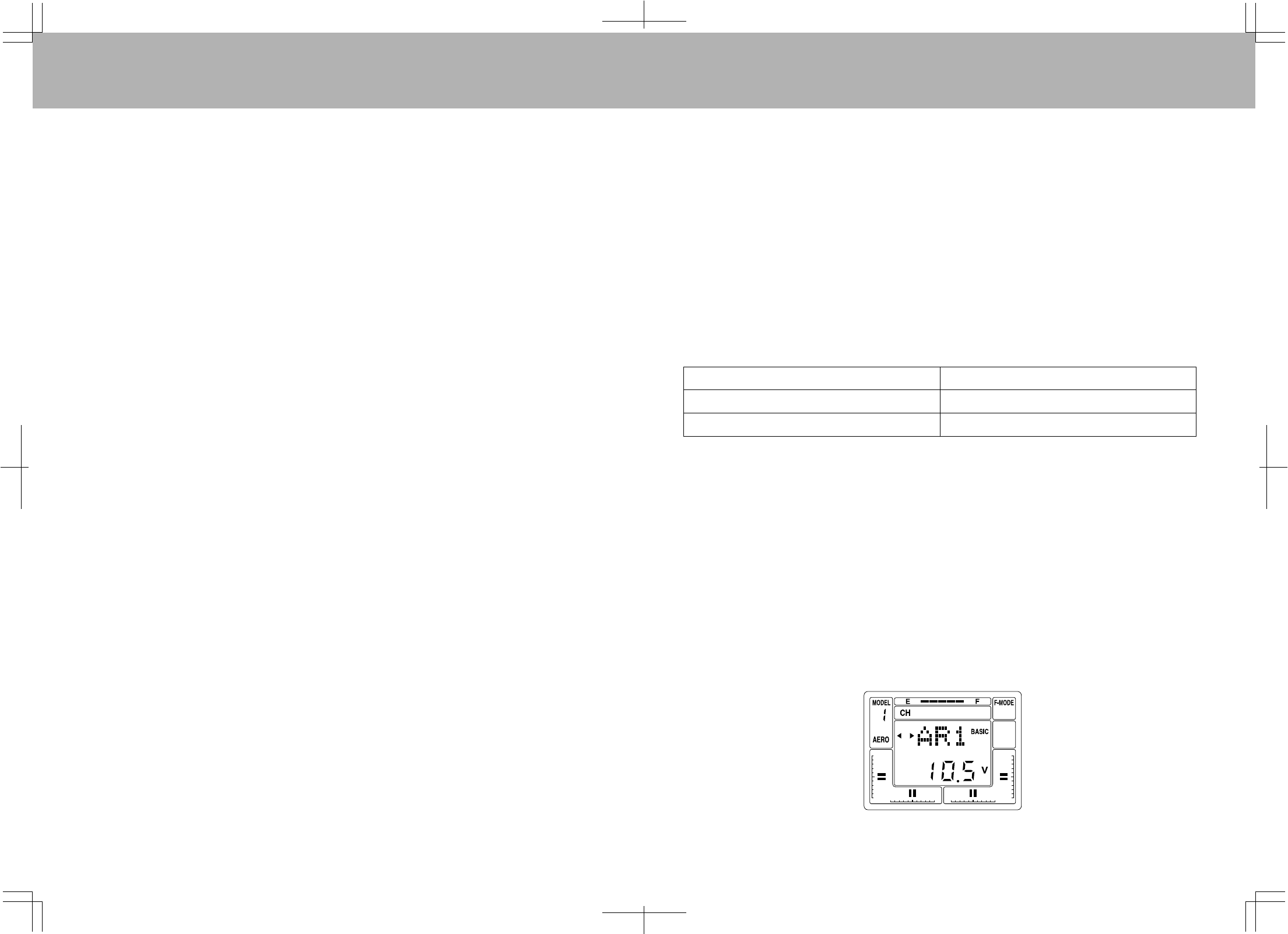
BARGRAPHVOLTAGEINDICATOR
1918
DropthethrottlesticksofthetransmittertoLOW.WhenusinginHELImode,turntheflightmodeoftheFlight
ModeswitchestoNormal(N).
TurnthetransmitterpowerON.TheBINDLEDofthetransmitterlightsup.
∗IfanalarmsoundsandtheLEDdoesnotlight,thethrottlesticksandFlightModeswitchesareincorrectly
positioned.RepeatthesettingprocedurestartingfromStep1.
TurnthereceiverpowerON.TheLEDsofthetransmitterandreceiverlightup.Atthispoint,trymovingthe
transmitter'sstickstoseeiftheservoisoperating.Ifitdoesnotappeartobeoperating,repeattheBIND
procedure.
Movethetransmitterstickstothedesiredfailsafeposition.Whileholdingthesticksinthosepositions,press
andholdtheBINDkeyofthereceiver.Soonafter,theBINDLEDsofthereceiverstartflashingslowly,then
flashrapidlyandultimatelystaylit.Thisindicatesthatthefailsafewassetsuccessfully.
*PressandholdtheBINDkeyofthereceiveruntilthereceiver'sBINDLEDsstaylit.
TurnthetransmitterpowerswitchOFFtointerruptthetransmissionsignalandcheckwhethertheservoshave
comeintothesetposition.Thischeckisforsafetypurposes,thereforeperformbeforetakeoff.
∗Tochangefailsafesettings,repeatsteps1-4.
1.
2.
3.
4.
5.
Asaconvenience,theRDS8000transmitterprovidesatransmitterbatteryBarGraphvoltageindicatoratthe
topoftheLiquidCrystalDisplaylabeled“E”and“F”.The“F”symbolindicatesFULLandthe“E”indicates
EMPTY.Youcanconsideritsimilartoagasgauge.TheBarGraphindicatorisinadditiontothenormal
batteryvoltagethatisdisplayedonthemainscreenwhenyouselectAEROorHELIbypushingtheEND
keytwice.WhentheBarGraphreadslessthanhalfyoushouldnotflyuntilyourechargethetransmitter.
(9.2V.)
3.ThetransmittersBINDLEDwillblinksteadily.ContinueholdingtheBINDbuttoninforapproximately5
secondsuntiltheLEDgoesoutandthenletgooftheBINDbutton.IftheLEDthenresumesasteady
blinking,thetransitiontoRangeCheckModewassuccessful.
4.ImmediatelyturnthereceiverON,walkabout30pacesfromtheaircraft(approximately90feet)and,with
helpfromanotherperson,checktomakesuretheservosmovewithoutproblem.
Ifthereisaproblemwithservosmovement,trymovingwhilemaintainingthesamedistancefromthe
aircraft,andcheckagaintomakesuretheservosmoveswithoutproblem.
Ifthereisstillaproblemwithservosmovement,checktomakesuretherearenoproblemswithservos
connectorconnectionsandsoon.Donotflytheaircraftuntilyouhavesolvedtheproblem.
∗RangeCheckModeautomaticallyturnsoffinabout3minutes,andthesystemchangestoNormal
Mode.
Besuretocheckservosmovementwhilecheckingthatthetransmitter'sLEDisblinking.IftheLEDhas
changedtoconstantlylitstatuswhilecheckingservosmovement,turnthetransmitterpowerOFF.
Repeattheprocessfromstep1,thengointoRangeCheckMode.
∗Inthiscase,itisnotnecessarytoturnthereceiverOFF.
∗Caution!DonotflytheaircraftwhileinRangeCheckMode.Youwillbeunabletocontroltheaircraftonceit
hasflownacertaindistance.
RangeCheckMode
ThecontrollerhasaRangeCheckModefunction,whichlowersthetransmitter'soutputleveltocheckradio
signalreception.Usethisfunctiontocheckradiosignalreceptionontheground,priortoflight.Tocheck
reception,putthecontrollerinRangeCheckMode,walkabout30pacesawayfromtheaircraft,andcheckto
makesuretheservomoveswithoutproblem.
HowtotransmittoRangeCheckModeandcheckrange
1.Dropthethrottlesticksofthetransmittertotheendofthelowside.WhenusinginHELImode,turntheflight
modeoftheFlightModeswitchestoNormal(N).
2.Whilepressingthetransmitter'sBINDkey,turnthetransmitterpowerON.
∗Ifyouhearawarningsignal,correctthepositionsofthethrottlesticksandFlightModeswitches,andrepeat
thesettingprocedurestartingwithStep1.
Mode TransmitterLEDstatus
RangeCheckMode(Lowtransmissionoutput) Steadilyblinking
NormalMode(Normaltransmissionoutput) Constantlylitup

2120
RDS8000AEROFEATURES
FEATURES
STW(Stopwatch)
REV(Reverse)
D/R(DualRate)
CNT(Center)
TRM(Trim)
EXP(Exponential)
EPA(EndPointAdjustment)
M-SL(ModelSelect)
TYP(TypeofModel)
INT(IntegralTimer)
RST(Reset)
CLK(Click)
NAM(Name)
SW-R(SwitchReverse)
CPY(Copy)
FLAPE(Flaperons)
DELTA(Elevons)
V-TAIL(RudderandElevator)
D/R-A(DualRateAlarm)
DESCRIPTION
Usedasastopwatchorto
countdowntoapresettime.
Reversestheservooperating
direction.
Adjustsservothrow.Availableon
ElevandAil.
Changesservoneutralposition.
TheLCDprovidesanindicatorof
thevalue,aswellasthedirection
ofthetrim.
Changesthelinearmovementof
theservototherelationofthe
stickmovement.Canbeset
PositiveorNegative.
Limitsthetotalmovementofa
servoineachdirection.
Selectmodels1to10.
ModelTypeAircraftorHelicopter.
Usedtoshowhowlongthe
transmitterhasbeeninuse.Can
beresettozero.
Clearsallsetupdatainanymodel
tofactorydefaultsettings.
Abeepsoundcanbeheardevery
timeyoupressatransmitterkey.
OptionsActiveorInoperative.
Youcanuseupto3charactersto
nameyourmodel.
Youcanreversethedefault
directionofallcontrolswitches.
Copyonemodeltoanother.
Activates2channelstobeused
forAilerons.
Aileronsoperateasaileronsand
aswellasElevators.Usedfor
flyingwings.
UsedforV-Tailmodels.
AlertsyouwhenaDualRate
switchison.OptionsOnorOff.
T-CUT(ThrottleCut)
C-MIX(CompensationMixing)
E>F(ElevatortoFlapMixing)
R>A(RuddertoAileronMixing)
R>E(RudertoElevatorMixing)
F>E(FlaptoElevatorMixing)
SPOIR(Spoilerons)
AI-DIF(AileronDifferential)
L-DIF(LandingDifferential)
CR:LA(CrowLeftAileron)
CR:RA(CrowRightAileron)
OPT(OptionMenu)
Step(TrimStep)
BASIC(ON/OFF)
D-EL(DUALELEVATOR)
Youcansetthepointwherethe
throttlecanbecutusingthe
throttlecut-offbutton.
Abilitytomixamasterchannel
toanotherslavechannelwitha
C-MixSwitch.
AbilitytomixElevatortoFlap.
AbilitytomixRuddertoAilerons.
AbilitytomixRudertoElevator.
AbilitytomixFlaptoElevator.
Forsailplanes.Bothaileronswill
actasspoilersasthethrottle
stickisused.
Changesthetotalamountof
throwupanddowntoboth
aileronservosindependentlyto
helpstopanyadverseyaw.
AllowsAileroncontroltoremain
effectivewhenCroworSpoilers
areused(Sailplane).
Crowisusedtoslowthe
sailplanedown.Aileronsgoup
whenflapsgodown.Leftand
RightAileronsareadjustable.
Advancedprogramallowsyou
toturnofforonfunctiondisplays.
Setstheamountofmovementa
servowillmovewithonebeepof
thetrim.
TurnBasicmenuonoroff.
Activates2channelstobeused
fordualelevatorservos.
Ch1leftservo
Ch7Rightservo
FEATURES DESCRIPTION
RDS8000HELIFEATURES
FEATURES
STW(Stopwatch)
REV(Reverse)
D/R(DualRate)
CNT(Center)
TRM(Trim)
EXP(Exponential)
EPA(EndPointAdjustment)
M-SL(ModelSelect)
TYP(TypeofModel)
INT(IntegralTimer)
RST(Reset)
CLK(Click)
NAM(Name)
SW-R(SwitchReverse)
CPY(Copy)
T-CUT(ThrottleCut)
DTM(DynamicTrimMemory)
GYR(Gyro)
CV-P#(ThrottleCurve)
CV-P#(PitchCurve)
RV(RevolutionMixing)
C-MIX(CompensationMixing)
STEP(TrimStep)
SWH(CyclicType)
BASIC(ON/OFF)
OPT(OptionMenu)
DESCRIPTION
Usedasastopwatchortocountdowntoapresettime.
Reversestheservooperatingdirection.
Adjustsservothrow.OnElev,Ailand(RudinHELIMode)
Changesservoneutralposition.
TheLCDprovidesanindicatorofthevalue,aswellasthedirectionofthetrim.
Changesthelinearmovementoftheservototherelationofthestickmovement.Can
besetPositiveorNegative.
Limitsthetotalmovementofaservoineachdirection.
Selectmodels1to10.
ModelTypeAircraftorHelicopter.
Usedtoshowhowlongthetransmitterhasbeeninuse.Canberesettozero.
Clearsallsetupdatainanymodeltofactorydefaultsettings.
Abeepsoundcanbeheardeverytimeyoupressatransmitterkey.OptionsActiveor
Inoperative.
Youcanuseupto3characterstonameyourmodel.
Youcanreversethedefaultdirectionofallcontrolswitches.
Copyonemodeltoanother.
Youcansetthepointwherethethrottlecanbecutusingthethrottlecutoffbutton.
Memorizestrimsineachflightmode.
Gyrosensitivityforeachflightmode.
Tosetupacurveinallflightmodes.
Tosetupacurveinallflightmodes.
Tailrotoroffsetmixing.
AbilitytomixamasterchanneltoanotherslavechannelwithaC-MIXswitch.
Setstheamountofmovementaservowillmovewithonebeepofthetrim.
5CyclicOptions(Normal,CP3F,CP3B,CP4F,CP4B).
BasicmenuONorOff.
Advancedprogramallowsyoutoturnofforonfunctiondisplays.
Usedtoprovideaswitchablehighandlowservothrow.Thiscanbeusedtoprovide
moresurfacemovementfor3Daerobatics,andloweramountforprecisionflight,for
example.
2322
SECTIONIICOMMONFUNCTIONS
ThefollowingfunctionsarecommonandapplicabletobothAircraftandHelicopterprogramming.
TheLiquidCrystalDisplayshowsanAEROmodelselected.However,asimilarscreenwillbedisplayedwhena
Helicoptertypemodelisselected.
NOTE:Switcheslabeledwithredletteringareforaircraftandblueletteringisusedforhelicopter.
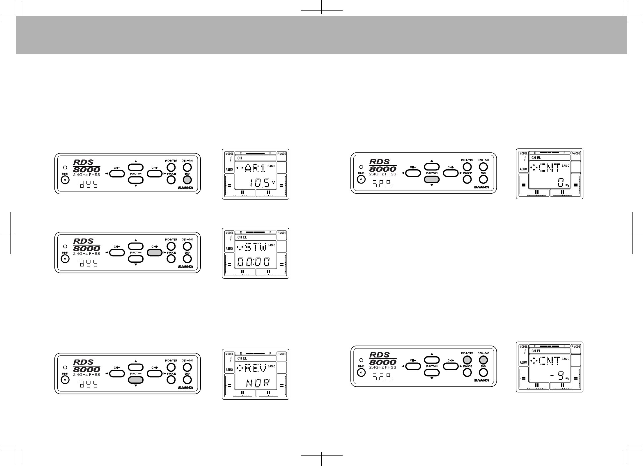
IMPLEMENTATIONOFCONTROLFUNCTIONS
Inthissectionyouwilllearnhowtoimplementthecontrolfunctionsandtailortheservomovementand
centeringforeachcontrol.PressingtheENDkeyonthefrontpanelseveraltimeswillbringyoutothe
followingscreen,i.e.,theinitialscreenthatindicatesthecurrentmodeltypeandnumber,andthetransmitter
NiCdbatterypackvoltage.
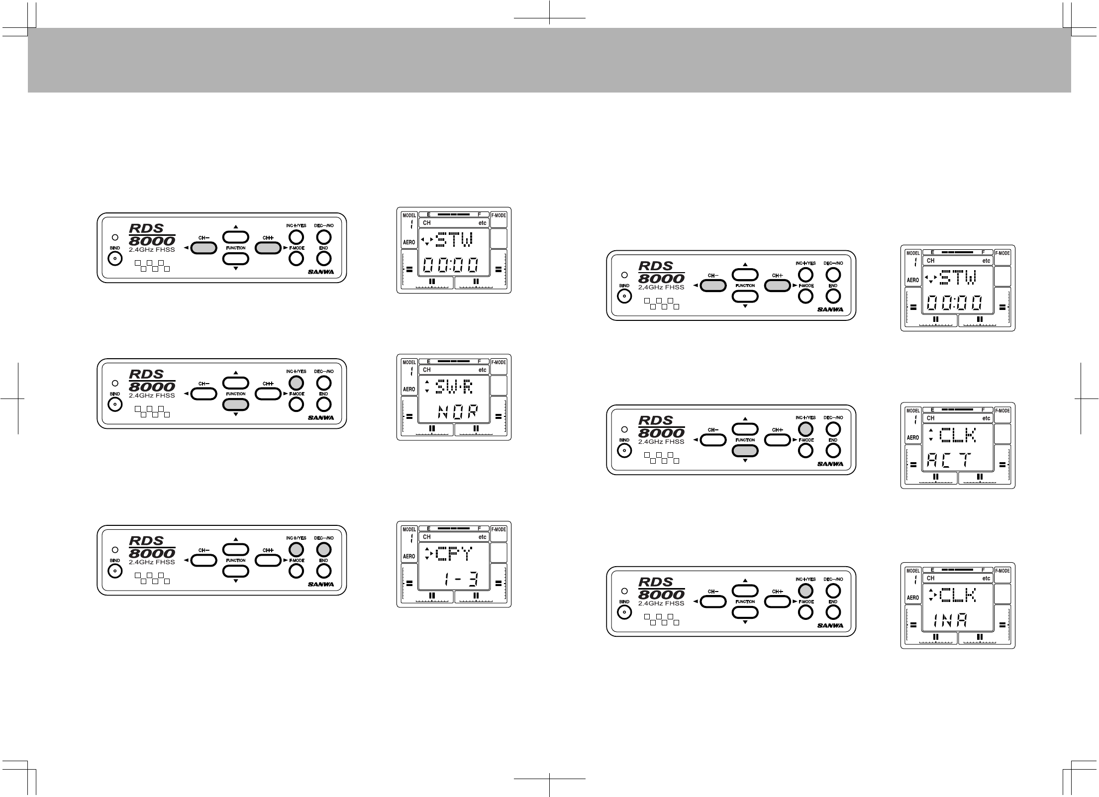
Pressthe(CH+)keytoobtaintheSTWscreen.TheElevatorchannelwillappearontheupperpartofthe
screen.ThemodelnumberandAEROwillbepresentontheleftsideandthestopwatchwillindicatezero
sincenotimehasbeenprogrammed.
REV(SERVOREVERSING)
TheRDS8000allowsyoutoelectronicallyREVERSEthedirectionofrotationforeachoftheservosinuse.
Thisallowsyoutohookupyourcontrollinkagesandpushrodsinthemostmechanicaldesirablemanner
withoutregardtothedirectionofservomovement.Afterinstallingyourlinkages,checktoseeifanyofthe
servosmoveinthewrongdirectionwhenyoumovethecontrols.Ifsoproceedasfollowsforreversingthe
elevatorchannel.Reverseforallotherchannelsisdonethesameway.
PresstheFUNCTIONdownkeytoarriveatthefollowingscreen:
Movethecontrolstickfortheelevatorfunction.
IftheElevatorservomovesinthewrongdirection,presstheINC+/YESkeytochangethedirection.
Movethecursortothechannelwhosedirectionyouwishtochange(oneofthefollowing:EL,AL,TH,RU,G,
P/F,7or8)andsetREVfunction.
CNT(CONTROLCENTERING)
YourRDS8000allowsyoutofine-tunetheCENTERorneutralpositionoftheservos.Afterhookingu
pyour
controlsandmechanicallycenteringalllinkagestotheapproximatepositions,presstheFUNCTIONdown
keytoarriveatthefollowingscreenfortheElevatorcontrol.
(NotethattheAileron,Throttle,Rudder,Flap,AUX-1andAUX-2centeringoperatesinthesamemanner
whenyouselectthatchannelontheupperpartofthescreen.YoucanmoveacrosstotheCNTfunctionof
eachchannelaswellassomeoftheotherfunctionsbypressingthe(CH+)key.
BypressingtheINC+/YESorDEC-/NOkeysyoucanvarythevaluefrom0to+or-100%.Defaultis0%.
IMPORTANTNOTE:
Itisdesirabletoadjustthecontrollinkagesascloseaspossibletothecorrectcenterpositions,thenusethe
CNT(CENTER)commandsto“Fine-tune”theexactpositionofthecontrolsurfacewhenthetransmitter
controlisinneutral.
Usingalargeamountofelectroniccenteringadjustmentswilldecreasethetotalthrowavailableforthat
channel.Inparticular,centeringadjustmentsgreaterthan+or-50%willtendtomaketheextremestick
positionononeendlessresponsive!
2524
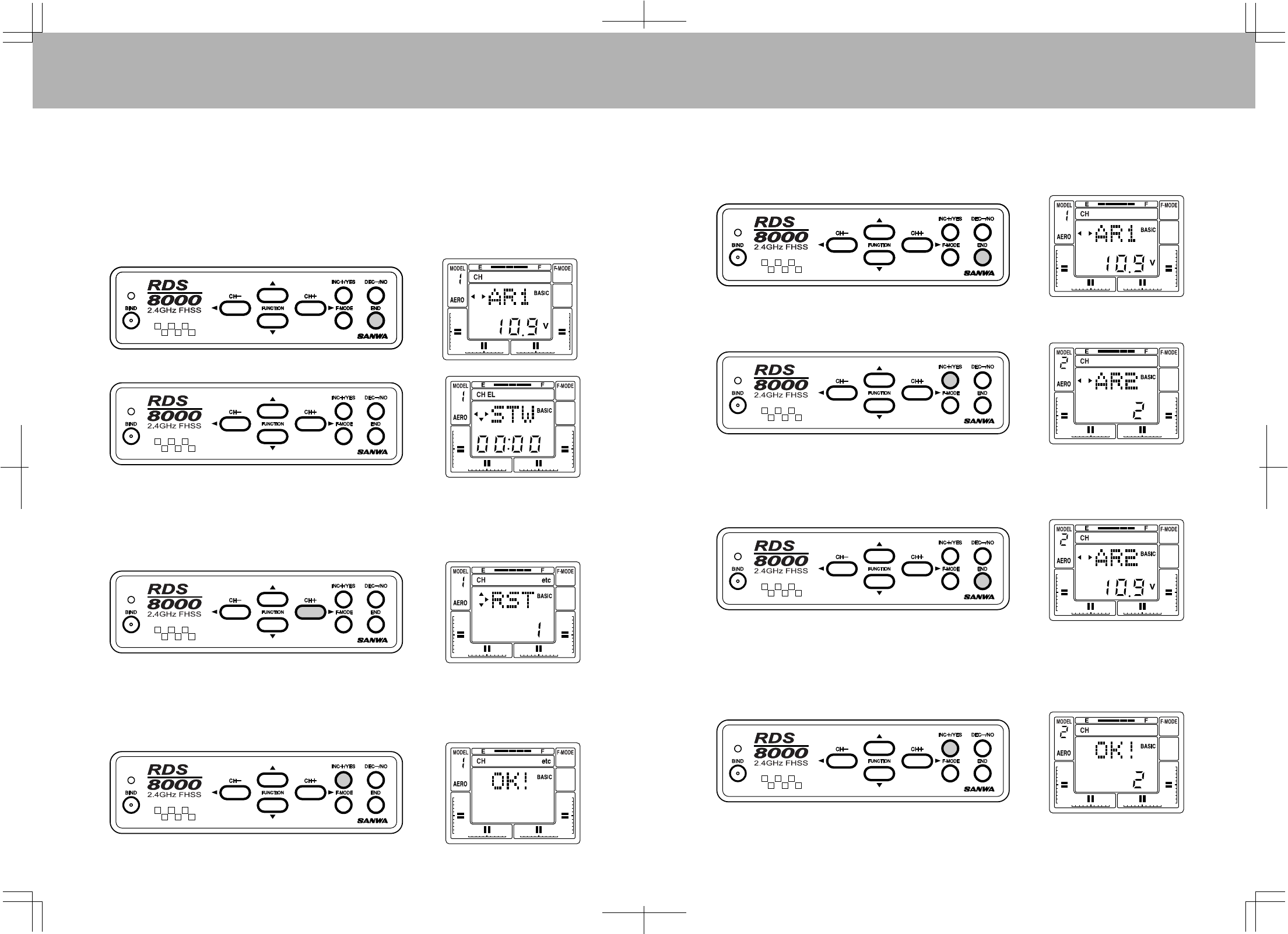
Ifyouwantto“UNDO”allofyourprogrammedparametersatonetime,youcanusetheRSTfunction.
However,becertainthatiswhatyouwanttodo,sincethisfunctionwillresetallsettingstothefactorydefault
settings.TheRSTfunctionwillonlyaffectthespecificmodelthatyouhaveselected.Allothermodelsin
memoryareunaffectedbytheRSTfunction.
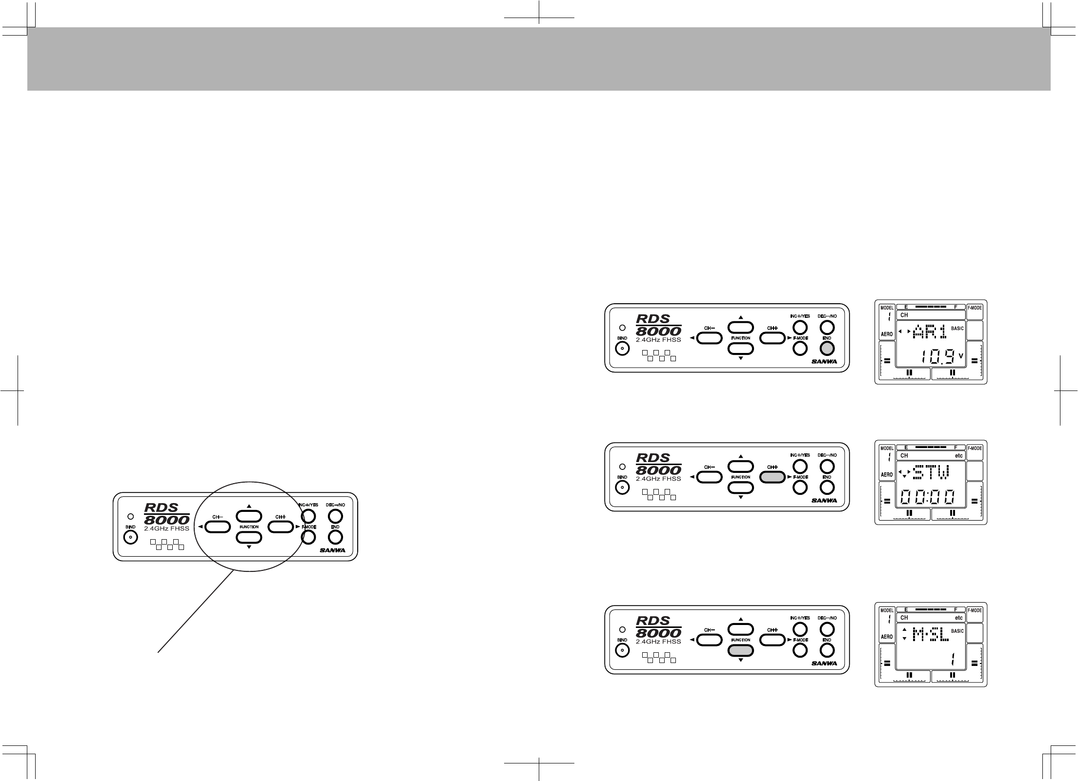
PresstheENDkeytoselecttheinitialAR1screenthatindicatestheTransmitterNiCdpackbatteryvoltage.
Now,presstheCH+toaccesstheSTW(Stopwatch)screen.Thisscreenallowsyoutomoveupanddown
aswellasleftandrightonthescreenintheRDS8000program.
RST(DATARESET)
First,presstheINC+/YESorDEC-/NOkeytoselectthemodelyouwouldliketoreset.Toresetalldatafor
thismodeltodefaultsettingspressthe(CH+)keyandthescreenwillflashYES.Now,presstheINC+/YES
keyandthescreenwillindicateOK!Allparamametersonthisspecificmodelnumberhavenowbeenresetto
defaultvalues.PresstheENDkeytwicetoreturntotheSTWscreen.
PresstheCH+keyseveraltimestomoveacrosstheCHindicatorportionofthescreenuntilitreads“etc”.
Now,presstheFUNCTIONdownkeythreetimestomovedowninthemenuuntilyoureachtheRST
(DataReset)screen.
HOWTOSELECTMODELSET-UPS:M-SL(ModelSelect)
TheRDS8000hasbuiltinmemorytostoretenmodelsetupsinanycombinationofmodeltypes.Touseor
modifyoneofthemodelsetupsyoufirstmustselectM-SLinthe"etc"menu.Assumethatyouwanttoselect
asecondmodel.Todoso,presstheENDkeytobringuptheinitialscreenthatindicatestransmittervoltage
andmodelnumber.
Pressthe(CH+)keytoscrollto“etc”.UsetheFUNCTIONdownkeytoselectMSL.NextpresstheINC+/
YESkeyandthescreenwillflashMSLtoindicateyoucanselectasecondmodel.PresstheINC+/YESkey
againtoselectthenextorfollowingmodelsuchasAR2.
PresstheENDkeythreetimestoreturntotheinitialscreenwhichwillshowthemodelnumberandthe
transmitterbatteryvoltagereading.
NOTE:ifthemodeltypeisincorrect,i.e.,HELIratherthanAERO,continuewiththemodelselection
procedure.ThemodeltypecanthenbeselectedontheTYPscreen.
TYP(MODELTYPE)
To selectthetypeofmodelyouwishtoprogram,pressthe(CH+)keytoscrollto“etc”.Nextpressthe
FUNCTIONkeytoselectTYP.Nowpressthe(CH+)keytoselectthenextmodeltype,eitherHELIorAERO.
ThescreenwillflashYESwiththetypeofmodelindicatedontheLCDdisplay.To confirmyourselection,
presstheINC+/YESkeyandthescreenwillindicateOK!
PresstheENDkeythreetimestoreturntotheinitalscreenthatwillthenshowyourmodelnumber/typeand
transmitterbatteryvoltage.
2726
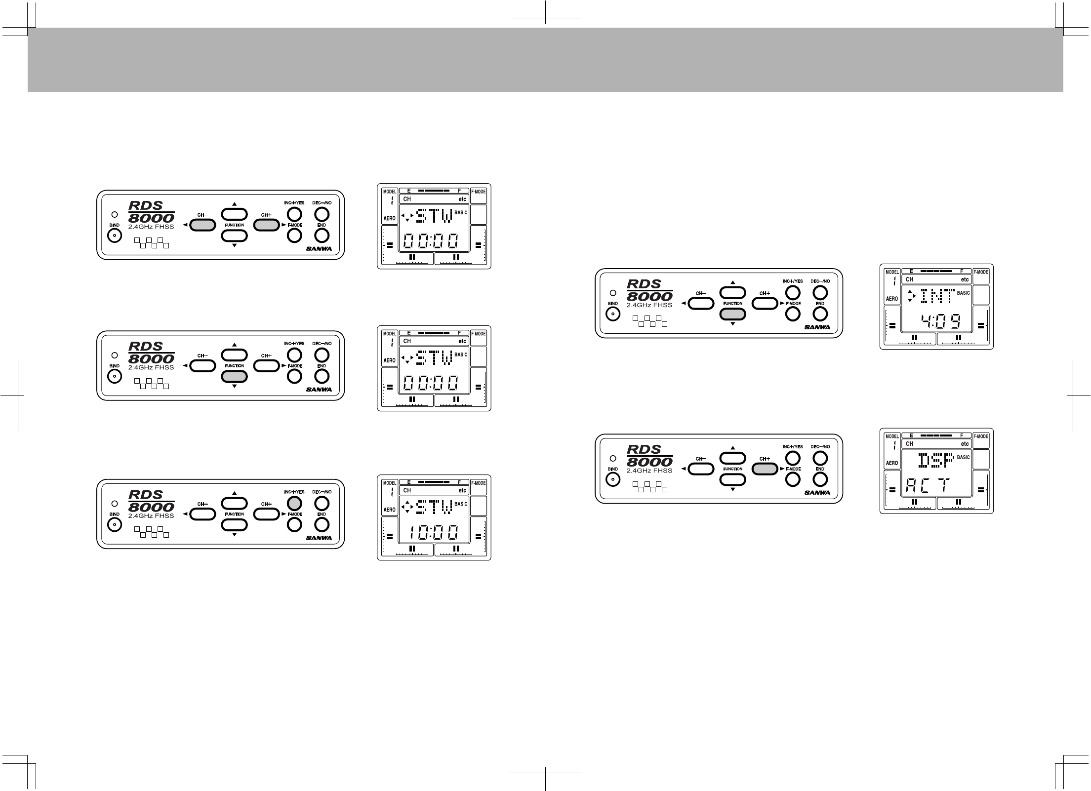
STW(STOPWATCH)
TheRDS8000offersabuilt-intimerandallowsthepilottousethestopwatchfunctionineitherelapsedtime
orcountdownmode.
NOTE:Toprogramatime,youmustbeintheBASICOFFmodeofoperation.
To usethestopwatch,presseitherthe(CH-)orthe(CH+)keytoselect“etc”ontheChannelindicatordisplay.
NowpresstheFUNCTIONdownkeytoscrollthroughthescreensuntilyoufindtheSTWscreenwiththe
flashingindicator.Thisiswhereyousetyourstopwatchcountdowntime.TheSTW(set)screenisjustabove
theINTscreenasshownontheMenuStructure,page38.
UsetheINC+/YESkeytosetavalueforthestartofyourcountdown.Asanexamplesetitat10.00minutes.
Thescreenwilllooklikethefollowingillustration.Ifyouwanttodecreasethetime,usetheDEC-/NOkey.
Ifyouwanttoclearthetime,presstheINC+/YESandtheDEC-/NOkeyssimultaneously.
Youcannowstartthestopwatchfromanychannel-indicatorscreenthatdisplaystheSTWscreenandthe
programmedtime.PresstheINC+/YESkeytostartorstopthecountdown.
Whenthetimereaches10seconds,atonewillbeheardeverysecondasitcountsdowntozero.Whenthe
timerreacheszero,asteadytonewillbeheardanditwillstartcountingup.PresstheINC+/YESkeyand
DEC-/NOkeysimultaneouslytoresetthetimertoyourpreviously-programmedtime.
INT(INTEGRALTIMER)
TheIntegralTimerfunctionoftheRDS8000isactivatedeachtimethetransmitterpowerswitchisturnedon,
andcountsupto99hoursand59secondsatalltimeswhenthetransmitteristurnedon.Thisindicateshow
manyhoursofactualuseyouRDS8000transmitterhasoperated.Youmayresetthetimertozeroatcertain
intervals,forinstance,eachtimeyouchargethetransmitterNiCdbatterypack.
TheINT(IntegralTimer)functionislocatedinthe“etc”columnofthemenu,directlybelowSTW(set).Use
theFUNCTIONdownkeytoaccesstheINTscreen.Notethatitwillhavesomeindicationofhowlongthe
transmitterhasbeenoperating.Itmaylooklikethefollowingscreen,butwithadifferenttimeshown.The
timewillshowachangeforeachelapsedsecondandminute.IfyouwanttoresettheIntegralTimertoZero,
presstheINC+/YESandtheDEC-/NOkeyssimultaneously.
YoucandisplaytheIntegralTimerfunctioninsteadoftheSTW(stopwatch)functiononallChannelscreens.
WhileyouareintheINTscreen,pressthe(CH+)keytoobtainthefollowingscreen.
PresstheINC+/YESkeyandthebottomlineofthescreenwillchangefromINH(inhibit)toreadACT(active).
YoucanpresseithertheDEC-/NOkeyortheINC+/YESkeytochangeitbacktoINH.Mostpilotspreferto
havetheStopwatchfunctiondisplayedonallChannelscreens,ratherthantheIntegralTimer,therefore,they
leavetheIntegralTimerDSPatINH(inhibit).PresstheENDkeytwicetogetbacktothetopofthe“etc”
menucolumn.
2928
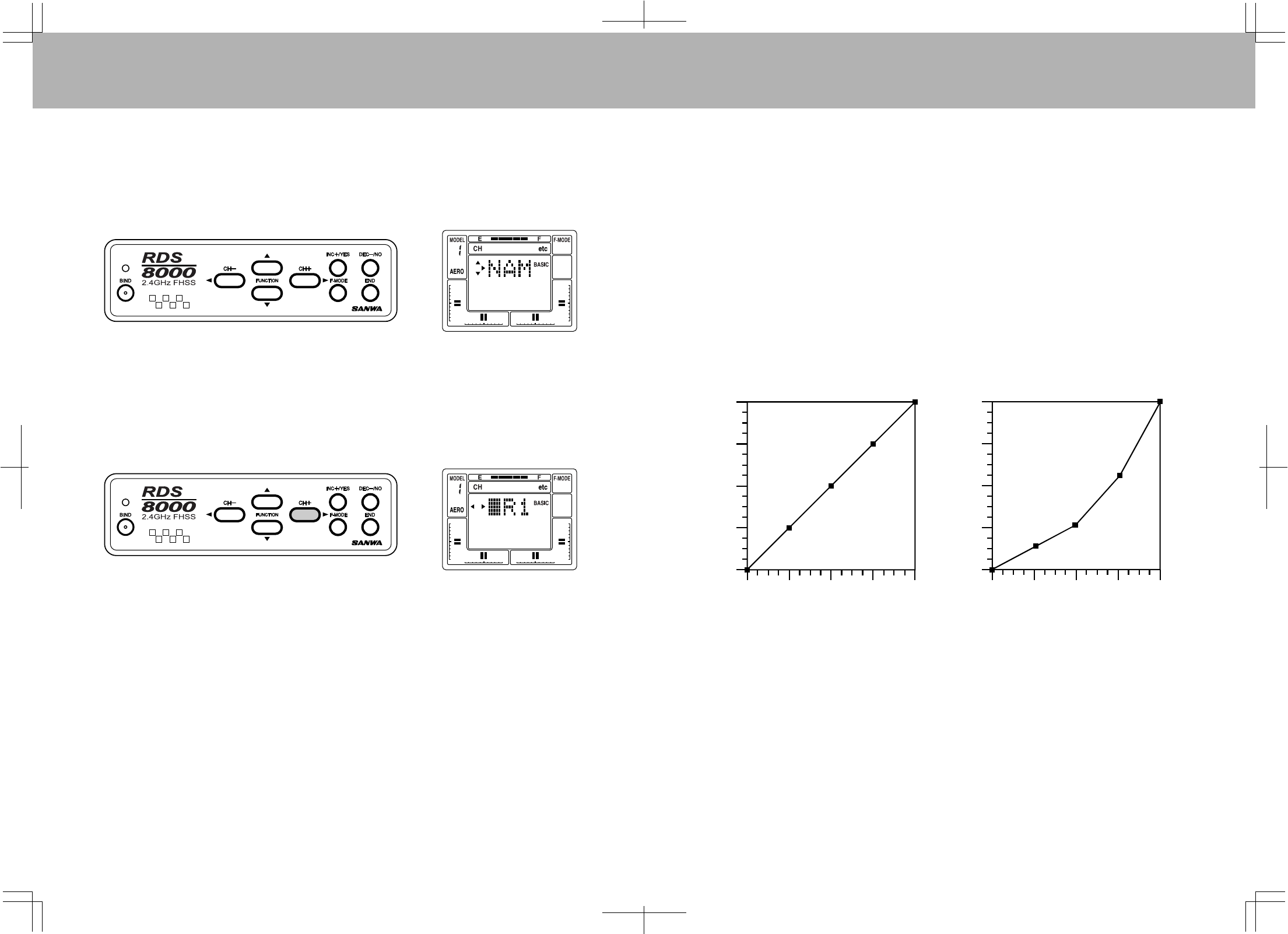
NAM(NAMINGYOURMODEL)
TheRDS8000providesthecapabilitytodesignateeachofthe10modelsyouhaveprogrammedbyuseofa
3digitname.Usethe(CH+)keytoselectthe“etc”screen.PresstheFUNCTIONdownkeytwicetoselect
theNAMscreen.
Nowpressthe(CH+)keytoselectthescreenformodelnumberone.Thefirstcharacterwillflashtoindicate
youcanchangethatletter.
PresstheINC+/YESkeytoscrollthroughthelettersofthealphabetandmakeachangeinthefirstletter.
YoumanyuseanycombinationofLETTERS(upperandlowercase),NUMBERS,Colon(:),Dash(-),
Character,orblankspacetodesignateamodel.Whenyouhavefinishedthefirstletterornumber,pressthe
(CH+)keytomovetothenextletterandsetitinasimilarmanner.TheDEC-/NOkeycanalsobeusedto
changealetterornumberintheoppositedirection.PressboththeINC+/YESandDEC-/NOkeys
simultaneouslytoreturntothedefaultsettingofAR1.Onceyouhavenamedthemodel,presstheENDkey
twicetoreturntothe“etc”columnheading.
0
25
50
75
100
02550
75 100
0
25
50
75
100
02550
75 100
ServoTravel
StickDeflection
LINEARTHROW EXPONENTIALTHROW
EXP(EXPONENTIAL)
TheRDS8000allowsthepilottochoosetwosettingsforExponentialthrowforeachofElevator,Aileron
(andRudderinhelicoptermode).
Exponentialthrowisprimarilyusedto“soften”ordecreasethesensitivityofacontrolstickaroundtheneutral
point.WithExponentialdisabled,aservowillmoveinproportiontotheamountofcontrolstickdeflection,i.e.,
50%stickdeflectionwillresultin50%servotravel;75%stickdeflectionwillresultin75%servotravel.
ExponentialsettingsDONOTchangetheamountoftravelavailableat100%stickdeflection,butratherit
changestheamountoftheservotravelatstickdeflectionslessthan100%.Thefirst25%ofstickdeflection
maybesettoresultinonly10%oftotalservo,throwmakingthecontrollesssensitivearoundneutral.Seethe
followingillustrations.
IfyouhavenotusedExponentialfunctionsbefore,youwillwanttostartwithasmallamountofExponential
(10to20%)todeterminewhetheryoulikethissortofcontrolresponse.Exponentialismostusefulwhere
strongcontrolresponseisdesiredatextremestickpositionsbutsofterresponsetosmallstickmovementis
desiredinordertomakeveryaccuratesmallcorrectionstotheflightpath.
TheswitchpositionsforExponential#1andExponential#2correspondtotheDualRateswitchpositionsof
ElevatorandAileron.Exponential#1iswiththeDualRateswitchinthedowni.,(Off)position.Exponential
#2iswiththeDualRateswitchUP(ON)position.(NotehoweverthatyoucanleavetheDualRate
adjustmentsforElevatorandAileronsetat100%whichisnorate,sothatswitchingaDualRateswitchON
willactivateExponentialonly.
NOTE:SettingtheExponentialwithapositivenumberwillmakeservomovementsoftintheneutralareaof
thestickmovement.SettingtheExponentialwithanegativenumberwillmakeservomovementfasterinthe
neutralareaandsofterattheendofthesticktravel.
ServoTravel
StickDeflection
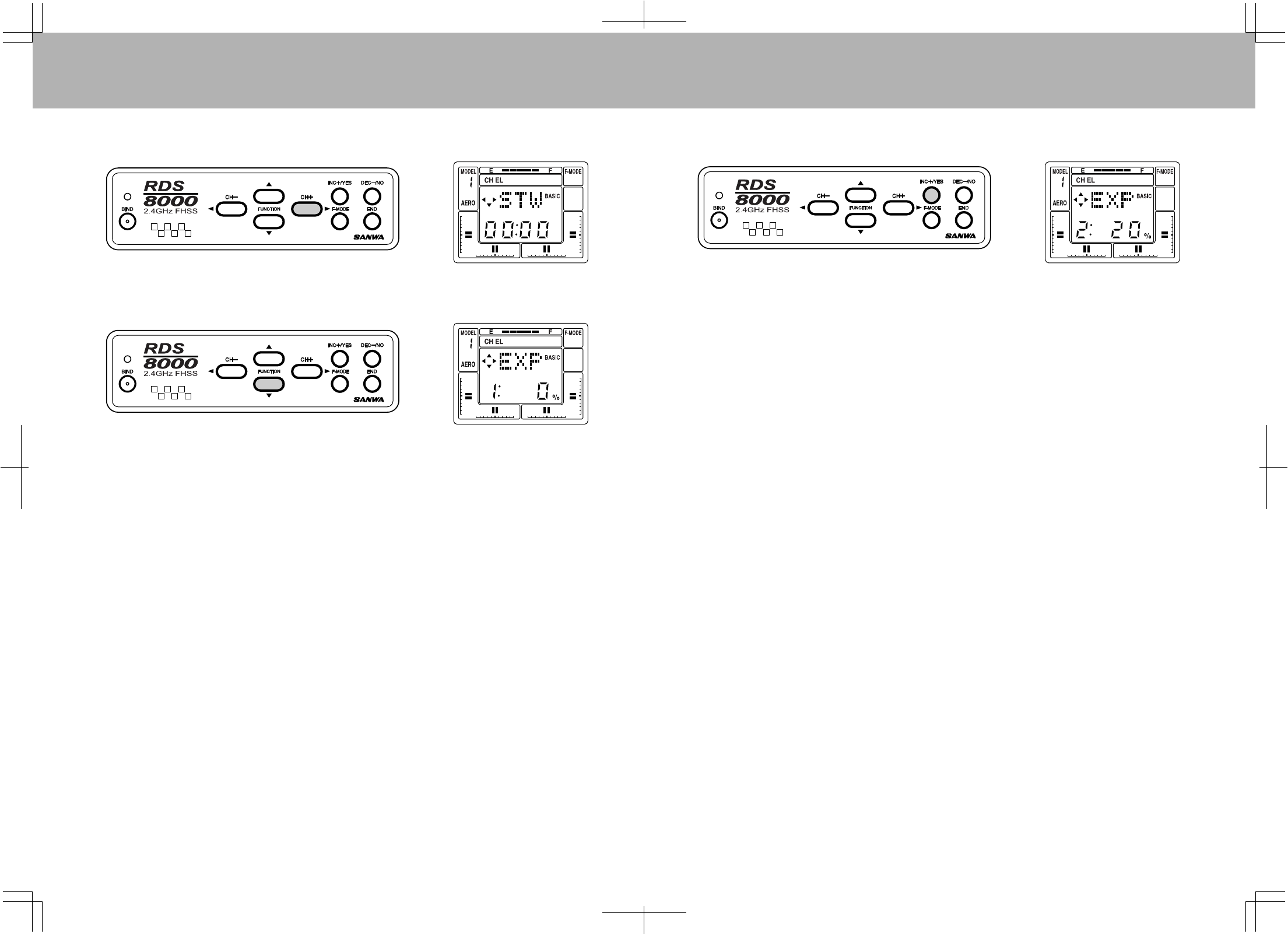
3130
Asanexample,tosetExponentialforelevator,access“EL”intheChannelareabyusingthe(CH+)key.
NowpresstheFUNCTIONdownkeytoselecttheEXPdisplayfortheElevatorChannelasshownbelow.
ThisscreenshowsyouthepresentExponentialstatusoftheelevatorchannelandwhenaDualRate
ExponentialswitchissettoONposition,theExponentialsettingforthatcontrolfunction.Thepossiblerange
forExponentialsettingsisfrom-100%to+100%.Notethat0%islinear.Anegativevaluewillspeedupthe
responseanditwillmakethestickmovementmoresensitivearoundtheneutralposition.
TosetanExponentialrateinthisexample,turntheDualRateswitchforElevatortotheONupwardposition.
NotethatthedisplaychangestoExponential#2.YoucansetthevaluefortheElevatorchannelExponential.
PresstheINC+/YeskeytosetapositivevalueofExponentialfunctionasindicatedbelow.
Intheaboveexample,wesetExponential#2tobe20%ofthemaximumfortheElevatorchannel.Thisisa
goodstartingpointfordeterminingthesuitabilityofExponentialthrowforyouraircraftandflyingstyle.
YoucanactuallyhavetwodifferentExponentialsettingsifyoudesire.Oneforswitchposition#1andanother
forswitchposition#2.However,whenyoufirststartusingExponentialthrow,itisusuallybesttoleavethe
switch#1positionat0%whichislinearthrow.
Ingeneral,largeamountsofExponentialareusefulonlywhereverylargecontrol-surfacedeflectionis
requiredatextremethrow,whileverysmallamountsofcontrolresponsearenecessaryforsmallercontrol
stickinputs.OneexamplewherelargeExponentialsettingsmaybeusefulisthehighlymaneuverable
“CompetitionFUNFLY”stylemodel.Formostsportandaerobaticmodels,anExponentialsettingfrom
+10%to+25%willgivethedesired“softness”aroundneutral.
CAUTION:ProceedwithcarewhensettingExponentialfunctionstoensurethatyouwillhaveadequate
controldeflectionavailableinanypossibleswitchposition.SettingExponentialtoaveryhighor100%
settingwillrequireverylargestickmovementstoachievesmallcontrolresponses.Alwaysmakesurethat
youareawareofthepresentstatusofanyrateassignmentsthatyouhaveselected!Forthemostflexibility
insettingupanaircraftmodeltoyourliking,studytheavailableoptionsforDualRates,EndPoint
Adjustments,andExponential.Thecombinationsoftheseoptionsallowsseveralpossibleset-ups.
TheExponentialfortheAileronChannelissetinthesamemannerasfortheElevator.
TheAID/RswitchlocatedabovetherightstickassemblyisusedwhensettingtheExponentialThrow.
3332
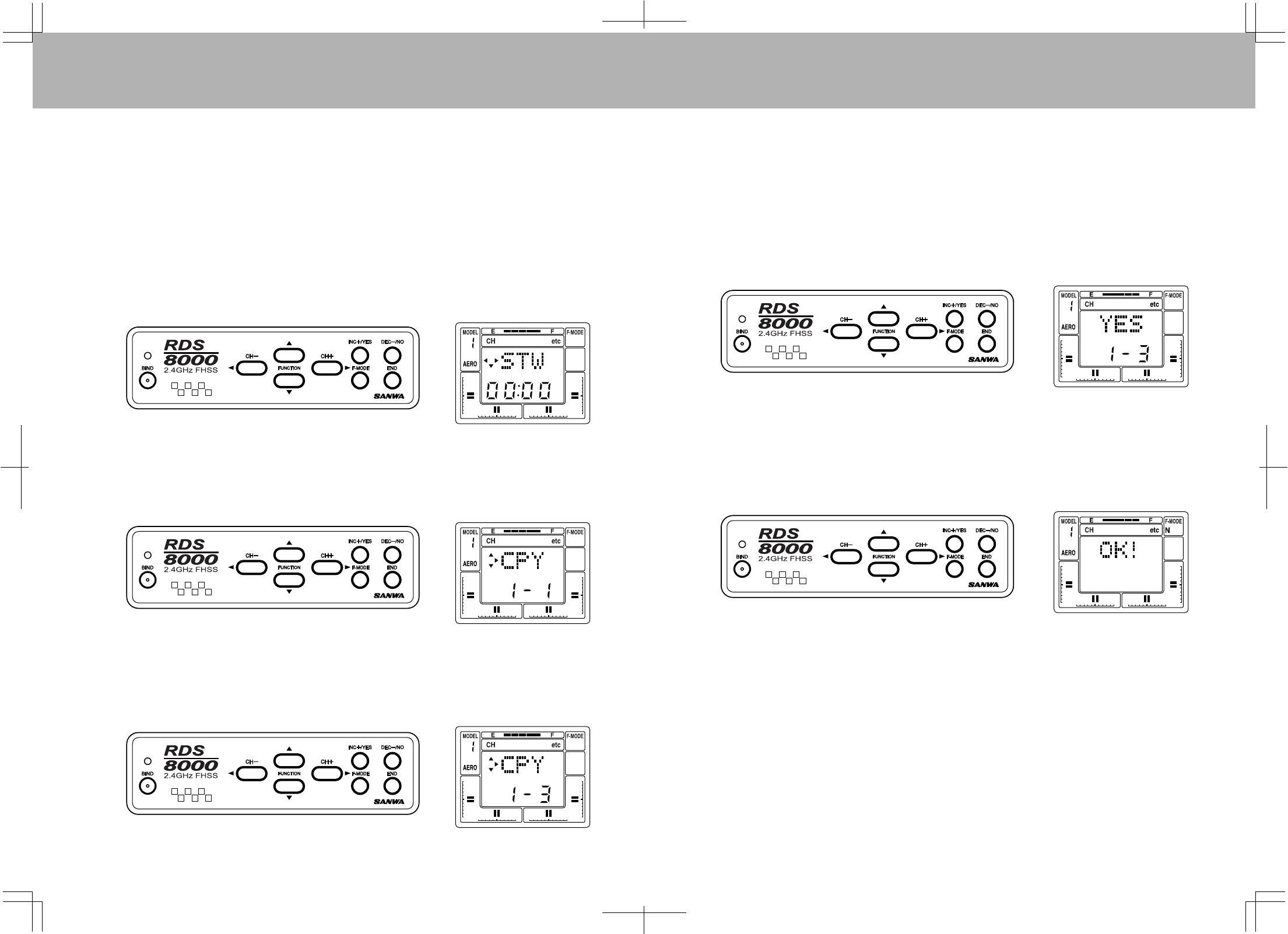
CPY(DATACOPY)
AvaluablefeatureoftheRDS8000istheDataCopyFunction.Withthisfunction,theentiresetofcontrol
parametersforoneaircraftcanbe‘copied’fromonemodelset-upintoanother.Forinstance,ifyouhave
youraircraftprograminModel#1andnothinginModel#3,youcancopytheModel#1programintoModel
#3withthecopyfunction.
Havingcopiedyourcontrolset-up,youcannowuseMSL(ModelSelect)toaccesstheModel#3program
andthenmakecontrolchangestothatset-up.Thisallowsyoutoexperimentwithdifferentcontroloptions
withoutchangingyouroriginalparameters(inthisexampleModel#1).
TousetheCPY(copy)function,select“etc”ontheChannelindicatorusingeitherthe(CH–)or(CH+)key.
NotethatyoumustbeontheSTWscreentomovehorizontallyacrossthescreento“etc”.
PresstheFUNCTIONdownkeytoselecttheCPY(copy)Function.
Forthisexample,assumeyouwanttocopytheset-upofModel#1(whichyouselected),toModel#3.The
firstnumberonthescreenindicatesthemodelnumberyouarecopying.Thesecondnumberindicatesthe
destinationmodel.PresstheINC+/YESkeytochangethedestinationtoindicateModel#3.Notethatone
ofthesmalltrianglesisblinkingwhichindicatesthereisanotherscreenassociatedwiththisfunction.
Onthepreviousscreen,thedestinationhasbeensettoModel#3.MAKECERTAINthatthecurrentmodel
setupisnotoneyouwishtosave,becausewhenyoucopytheModel#1set-upintoModel#3,alldatathat
wasinModel#3isreplacedwiththeModel#1data!AtthispointModel#3dataisstillintact,soifyouwish
tochangethedestinationforthecopieddata,dosobeforeproceeding.
Havingselectedboththedatasource(Model#1)andthedesireddestination(inthisexampleModel#3),you
cannowproceedtoconfirmthecopyfunction.
PresstheCH+>keytoaccessthenextscreenasshownbelow.The“YES”willbeblinking.
PresstheINC+/YESkeytoconfirmyourdatacopyfunction.Thescreenwillchangetothefollowingscreento
informyouthattheprocesshasbeencompleted,andthatModel#1andModel#3nowhavethesamedata.
PresstheENDkeytoreturntotheCPYselectscreen.
3534
SW-R(SWITCHREVERSE)
TheSW-RFunctionallowsyoutoreversetheactionofthesixtoggleswitcheslocatedonyourRDS8000
transmitter.ThedefaultoftheSW-RFunctionistheNOR(normal)position.CAUTION!Theswitchreversal
functionisnotindividuallyselective.IfyouchangeitfromNOR(normal)toREV(reverse),allswitcheswillbe
reversedintheiraction!
ToaccesstheSW-RFunction,select“etc”ontheChannelindicatorusingeitherthe(CH-)orthe(CH+)key.
NotethatyoumustbeontheSTWscreentomovehorizontallyacrossthescreento“etc”.
PresstheFUNCTIONdownkeytoscrolldowntotheSW-R(switchreverse)screen.
Now,presstheINC+/YESortheDEC-/NOkeytochangetheindicationfromNORtoREV.Allswitcheson
thetransmitterarenowreversedintheirfunction.PressENDtoreturntotheSTWscreen.
NOTE:NOR(normal)default(switchoff)position:Fortoptoggleswitchesistheuppositionandallfourslide
switchesonthefrontofthetransmitteraredownorpulledtowardsyou.UsingtheSW-Rfeaturewillchange
thedefaultoffposition:Totoggleswitchesdownandallfourslideswitchespushedforwardoruppositionas
defaultoff.
CLK(CLICK)
TheRDS8000transmitterisfactory-settoemitanaudiotone("Click")whenevertheprogrammingkeysare
pressed,whenvaluesarechanged,andwhenthestopwatchfunctionisstarted,stoppedorreachesthefinal
tensecondsofcountdown.
Itispossibletodisablethe“Click”oraudiotone,usingsoftwaresettings.Whendisabled,ONLYthestopwatch
count-downemitcauseanaudiotone.
Tosetordisablethe“Click”function,select“etc”ontheChannelindicatorusingeitherthe(CH–)orthe
(CH+)key.
PresstheFUNCTIONdownkeytoaccesstheCLK(CLICK)screen.
PresstheINC+/YESkeytochangetheindicationfromACTtoINH,todisabletheClickfunction.(pressing
eithertheINC+/YESortheDEC-/NOkeywilltogglethefunctionbetween“INHand“ACT”settings
PresstheENDkeytoreturntotheSTWscreen.
3736
T-CUT(THROTTLE-CUT)
AnotherusefulfunctionprovidedbytheRDS8000forengine-poweredmodelsisT-CUT,(ThrottleCut).
Normally
yousetyourthrottlestickintheextremelowpositionanduseEPAandthedigitaltrimtoobtaina
steadyengineidlespeed.However,tostoptheengineattheendoftheflightyouwouldhavetousethe
throttledigitaltrimandlaterre-trimforproperidle.TheT-CUTfunctioneliminatesthatbyprovidingabutton
thatoverridesthethrottlesticklowpositionanddrivesthethrottleservotoalowerposition,stoppingthe
engine.Thethrottlestickmustbeinthelowpositionforthethrottlecuttofunction.
InordertouseT-CUT,presseitherthe(CH-)orthe(CH+)keytoselectTHontheChannelindicator.
Next,presstheFUNCTIONdownkeyseveraltimestoobtainthefollowingscreen.
PresstheDEC-/NOkeytosetavalueof–100%.Placethethrottlestickintheextremelowposition.Press
andholddowntheThrottleCutbuttonlocatedabovetheelevator/aileronstickassembly.Thethrottle
servowillthenrotatefurthertoclosethecarburetorandstoptheengine.
RDS8000Transmitter-AIRCRAFT
C-MIX1,2
AUX-1
ElevatorDualRateSwitch
TrainerSwitch
Throttle(U/D)
Rudder(L/R)
ThrottleDigitalTrim
RudderDigitalTrim
PanelInputKeys
RetractSwitch
LiquidCrystalDisplay
AUX-2
AileronDualRate
Switch
ThrottleCutSwitch
MainPowerSwitch
FlapSwitch
ElevatorDigitalTrim
AileronDigitalTrim
Elevator(U/D)
Aileron(L/R)
92824ZReceiverChannelAssignments
ReceiverSlotNumber
1
2
3
4
5
6
7
8/B
PluginServoFor:
Elevator
Aileron
Throttle
Rudder
Gear
Flapor2ndAileronServo
AUX1
AUX2/Battery
3938
AIRCRAFTBASICMENUSTRUCTURE
(RxChannel)
(RxChannel)
CH EL AL TH RU G P/F 78etc
Usethefourcenterbuttonsinthefunctionpaneltonavigate
throughthemenu’s.(UP/DOWN/LEFT/RIGHT)
AIRCRAFTADVANCEDMENUSTRUCTURE
STW
REV
D/R
CNT
EPA
STW
REV
D/R
CNT
EPA
STW
REV
CNT
EPA
STW
REV
CNT
EPA
STW
REV
EPA
STW
REV
CNT
EPA
STW
REV
CNT
EPA
STW
REV
CNT
EPA
STW
M-SL
TYP
RST
BASIC
CH EL AL TH RU G P/F 78etc
STW
TRM
REV
D/R
EXP
CNT
EPA
E>F
STW
TRM
REV
D/R
EXP
CNT
EPA
A>R
STW
TRM
REV
CNT
EPA
T>E
T-Cut
STW
TRM
REV
CNT
EPA
R>A
R>E
STW
REV
EPA
STW
TRM
REV
CNT
EPA
F>E
STW
REV
CNT
EPA
STW
REV
CNT
EPA
STW
M-SL
NAM
MAS1
SLV1
E>E1
MAS2
SLV2
E>E2
STW
INT
STEP
TYP
SW-R
CPY
RST
CLK
Flape
Spoir
Delta
V-Tail
D-EL
Al-DIF
L-DIF
CR:LA
CR:RA
D/R-A
BASIC
OPT
PROGRAMMINGFORAIRCRAFT
INITIALSET-UPOFTYP(MODELTYPE)
TheRDS8000transmitterisfactory-programmedforfixed-wingaircraftmodelsandhelicoptermodels
asfollows:
Ifyouflyonlyfixedwingmodelaircraft,youcanchangemodels2,4,6,8and10toaircraft.
TurnthetransmitterpowerONandpresstheENDkeyuntilyoucometothedefaultmainscreen.Thisscreen
willshowAR1astheaircrafttype,andtheNiCdbatteryvoltage.
Pressthe(CH+)keytoscrollacrosstheCH(channel)indicatoronthescreento“etc”.
PresstheFUNCTIONdownKeyoncetoaccesstheMSL(modelselect)screen.
Model#1 issetupAERO Model#5 issetupAEROModel#9issetupAERO
Model#2 issetupHELI Model#6 issetupHELIModel#10issetupHELI
Model#3 issetupAERO Model#7 issetupAERO
Model#4issetupHELI Model#8 issetupHELI
4140
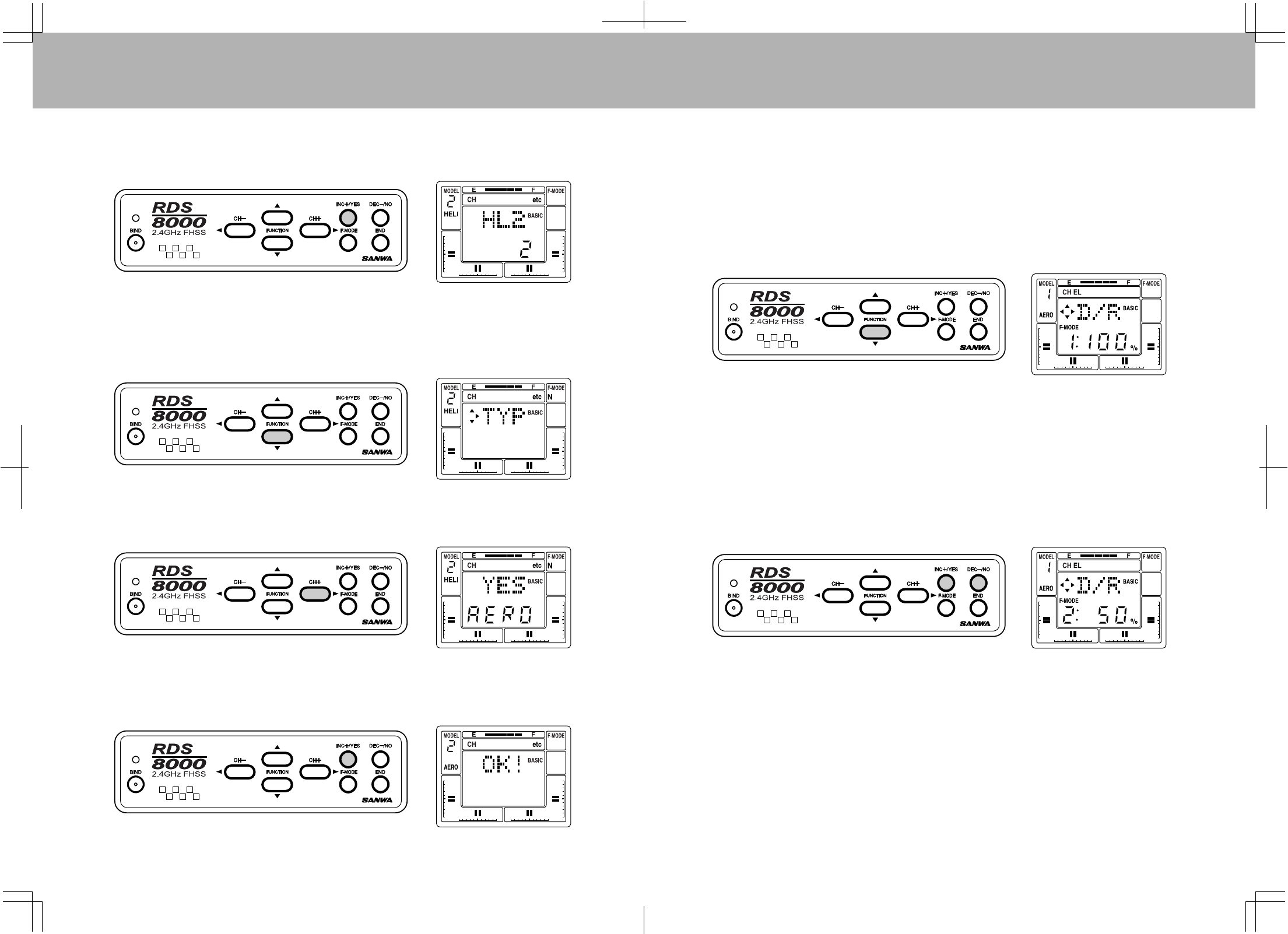
PresstheINC+YESkeyuntilthescreenreadsHL2(HELImodel2).NowpresstheENDkey.Thescreenwill
showmodelnumbertwo,whichisahelicoptersetup.However,sinceyouareafixedwingaircraftpilot,you
wantallofthetransmittersetupstobefixedwingaircraft,theTYP(type)ofaircraftmustbechangedfrom
HELItoAERO.
TYP(TypeofModel)
Tochangethetypeofmodel,presstheFUNCTIONdownkeytoselecttheTYP(modeltype)screen.
Notethatoneofthesmalltriangularindicatorswillbeblinkingtoshowthatyoushouldpressthe(CH+)key.
Therefore,pressthe(CH+)keyandthescreenwillchangetoAEROwithaflashingYES.
Toconfirmthechangeofaircrafttype,presstheINC+/YESkey.ThescreenwillthenchangetoreadOK!As
shownonscreenbelowtoindicatethemodeltypehasbeenchangedtoAEROformodel#2.PresstheEND
keytwicetoreturntotheSTWscreen.Thesameprocedureasabovecanbeusedtochangemodel#4,6,8
and10fromHELItoAERO.
D/R(DUALRATE)
TheRDS8000allowsDualRatesettingsforAileronandElevator.ToaccesstheDualRatesettingforElevator
whenyouareontheSTWorREVscreen,presstheFUNCTIONdownkeytoreachthisscreen.
Thescreentellsyouthepresentratestatus,andwhenaDualRateissettotheONposition,thealternate
rateforthatcontrolfunctionthatispresentlysetintheprogram.Weareshowinganexampleforthe
Elevatorchannel,however,alloftheotherchannelsaresetinthesameway.
TheDualRatesettingcanbevariedfrom0to150%.DefaultforDualRate1is100%.Werecommendyou
leaveitathatsettingandonlychangethesettingforDualRate2.i.e.,TheconventionforDualRatereduced-
throwistheswitchintheUPpositiontoTurnONDualRate.Whenyoudoso,notethattheScreenwill
appearasfollows.PresstheINC+/YESorDEC-/NOkeytoincreaseordecreasethevalue.Aninitialsetting
of50%isagoodstartingpointandyoucantailoritlaterfollowingatestflight.
TheDualRateswitchforAileronislocatedabovetherightstickassemblyandislabeledAID/R.Aileron
DualRatesareprogrammedinthesamemannerastheElevatorDualRates.TosetitforAileron,placethe
AID/RswitchintheupperpositionandusetheDEC-/NOkeytoreducethevalueshownonthescreento
somethinglessthan100%.
CAUTION:Priortotakeoff,checkthepositionofbothDualRateswitchestomakesuretheyareinthe
positionyouwant!
DualRateadjustments,whenoperatingyourRDS8000transmitterintheAEROmode,permitsyoutoswitch
fromyour"standard"controldeflectiontoareducedamountofthrowbysimplyflippingaswitch.Theactual
speedofthesignalprocessingandservomovementarenotaffectedbytheDualRatesettings,onlythe
amountoftotalthrowavailable.NotewhenoperatingtheHelicoptermode,DualRatesforElevator,Aileron
andRudderaresetforeachFlightMode.
TheRDS8000permitsyoutosetDualRateforthefourdistinctFlightModes,e.g.,Normal,1,2and3foreach
helicopter.Seepage67,PITCHCurves(FLIGHTMODES),forthedescriptionoftheavailableFlightModes.
DualRateinaspecificFlightModeissetbyfirstselectingD/RforElevator,AileronorRudder.PresstheF-
MODEkeytoscrollthroughFlightModeN,1,2or3andsetthevalueforDualRate.TheDualRatecanbe
variedfrom0to150%Thedefaultvalueis100%forallDualRates.