Sanwa Electronic Instrument Co ATX90354 Remote Control Transmitter User Manual RD8AT 002 003 eps
Sanwa Electronic Instrument Co Ltd Remote Control Transmitter RD8AT 002 003 eps
Contents
- 1. User Manual Part I
- 2. User Manual Part II
User Manual Part II
4342
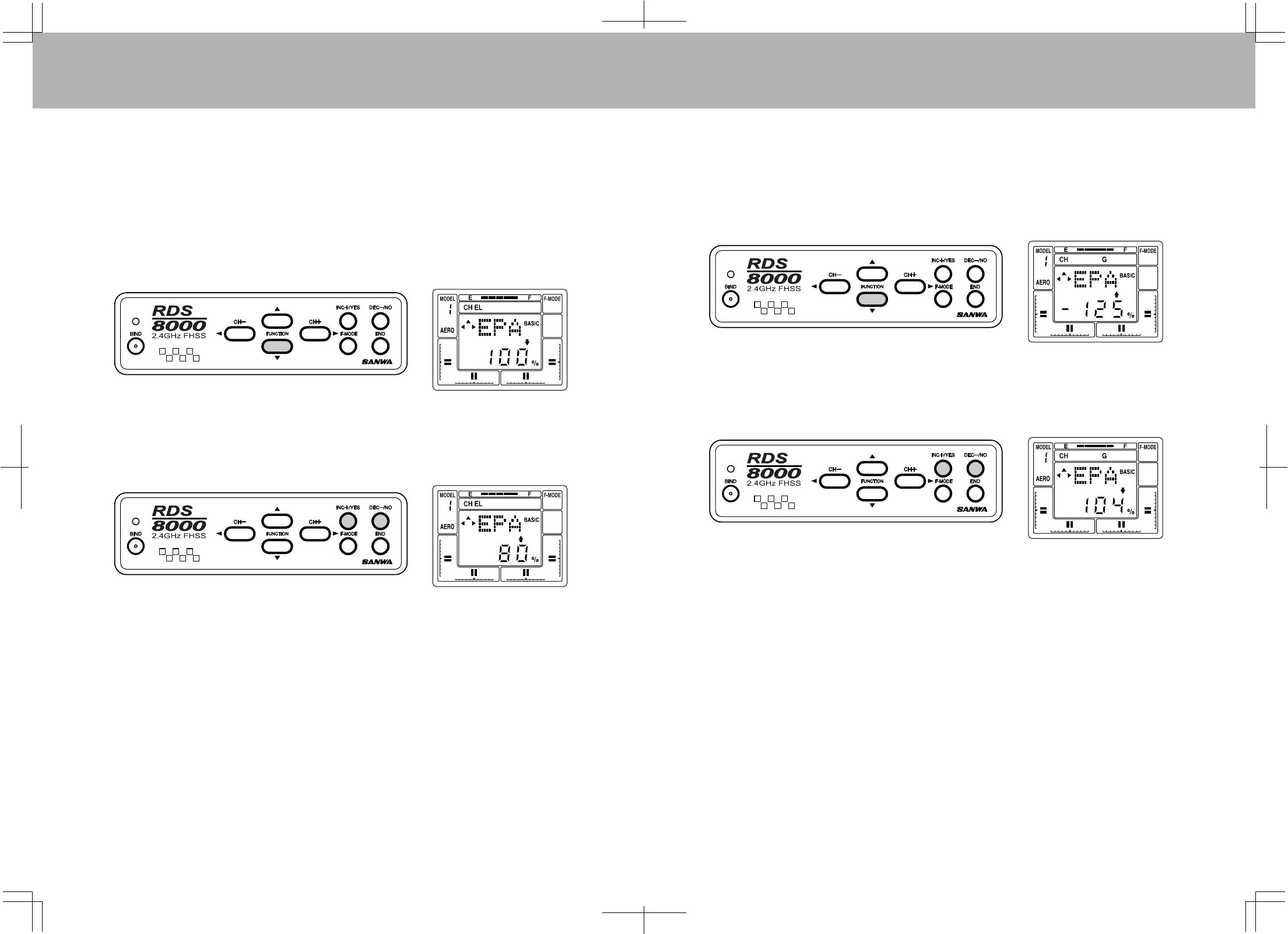
EPA(ENDPOINTADJUSTMENT)
TheRDS8000allowsyoutoadjustthe“EndPoint”,ortravellimit,forallflightchannels.
Ingeneral,itisbesttouseascloseto100%servothrowaspossible.Thisallowsforthebestpossible
resolutionandcenteringofcontrolsurfaces.However,insomecasesitisnotpossibletousefullservo
movement,suchaswhereshortcontrolhornsmustbeusedbecauseofaircraftdesignconsiderations,or
withfixed-lengthcontrolhornssuchasathrottlearm.
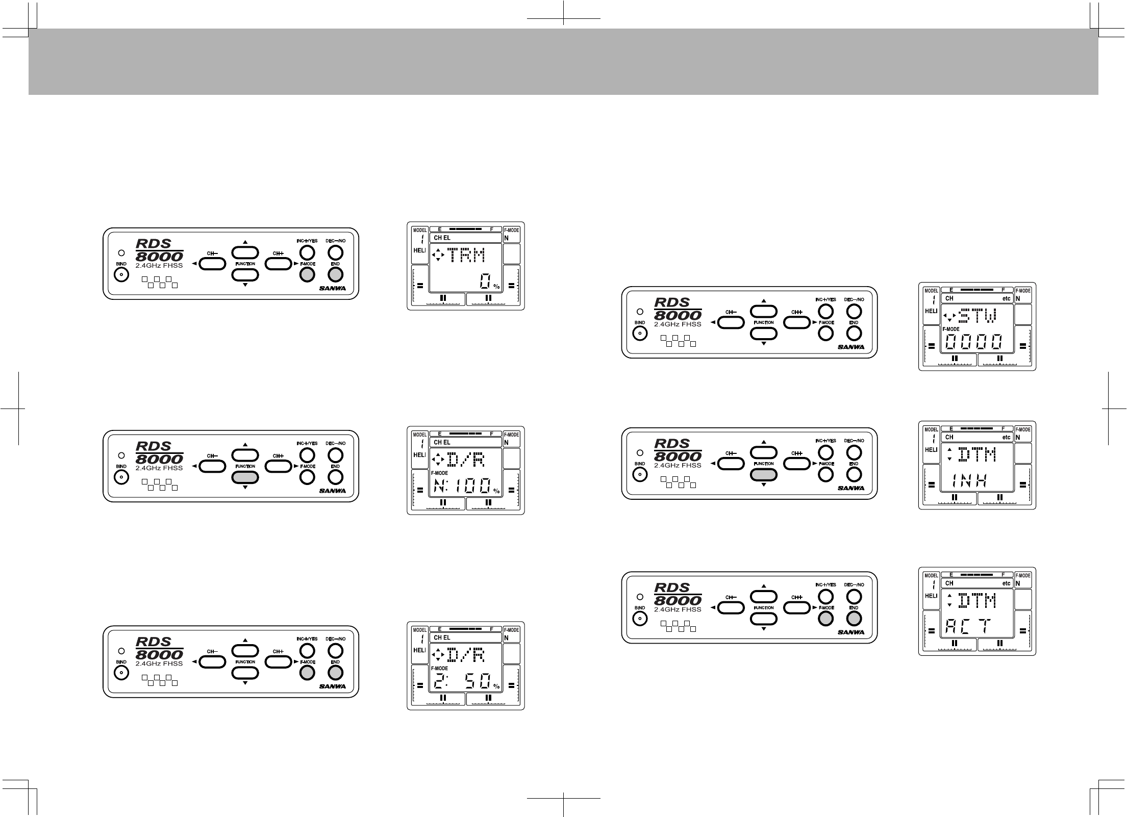
AssumeyouwanttoadjusttheEPAoftheElevatorchannelservo.BringuptheSTW(stopwatch)screenas
previouslyinstructedinINITIALSETUP.Next,presstheFUNCTIONdownkeyuntiltheEPAscreenappears
fortheElevatorchannel.
TheEPAoftheElevatorchannelcanbeadjustedfrom0%to150%.Bymovingtheelevatorstickupand
down,youwillseetheLCDarrowchangeaccordingtothedirectionyouaremovingthestick.TosettheUP
EPA,movethestickbackpasttheneutralpositionandreleasethestick.Youcanincreaseordecreasethe
amountbyusingthe(INC+)or(DEC-)functionkeys.
Notethatyoucanmoveacrossthemenuusingthe(CH+)or(CH-)keystoadjustEPAforallotherchannels.
ToadjusttheEPAonGearandFlapchannelssimplymovethetoggleswitchupordownandadjusttheEPA
accordingly.
G(LandingGearEndPoints)
Inmostcases,(almostallcasesinthepast)thetotalservothrowforthelandinggearfunctioncouldnotbe
setbythetransmitter,becausemostretractservosareSWITCHED(non-proportional)servos.Withthese
servos,mechanicaladjustmentwastheonlymethodavailabletoensureproperoperationoftheretracts.
Tousethisfunction,selecttheEPAfunctionasshownonthepreviousscreen.
Pressthe(CH+)keytoscrollacrosstheChannelindicatoronthescreenuntilyoureachG(LandingGear).
NotethatyoumustsetthevalueforUpandDownlandinggearbyuseoftheINC+/YESandDEC-/NOkeys.
ActivatetheLandingGeartoggleswitchlocatedontheupperlefttopofthetransmitterwhensettingthevalues
fortheLandingGear.Youcanvaryeachonefrom0%to150%.ThedefaultvaluesforLandingGearare
–125%and+125%.Torestorethelandinggearchanneltothedefaultvalues,presstheINCandDECkeys
simultaneously.
PresstheENDkeytoreturntotheSTWscreen.
4544
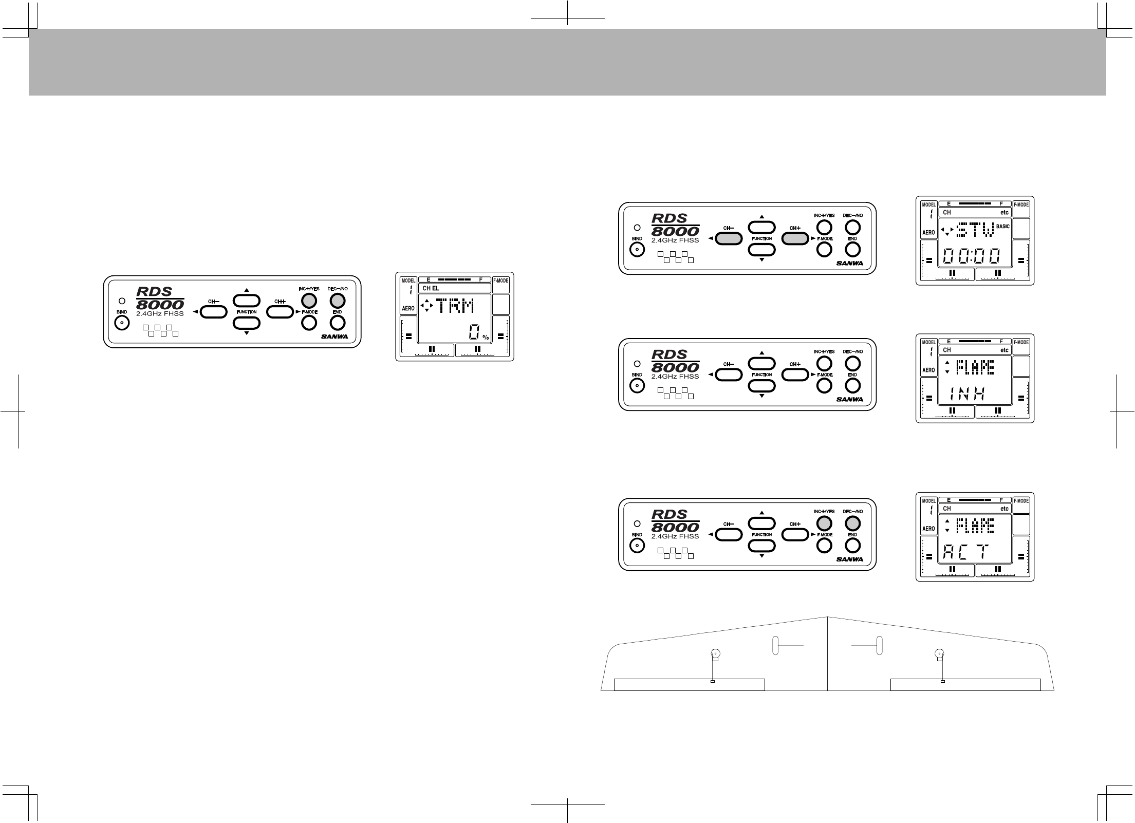
TRM(TRIMMEMORY)
TheRDS8000offerstheTrimMemoryFunctiononallfouroftheflightcontrolchannelsandtheFlapChannel.
TrimMemoryforElevator,Aileron,Throttle,andRudderisinputbytheDigitalTrimkeys.Itcanalsobeset
whenyouusetheINC+/YESorDEC-/NOkeystoinputtrim.
AnytrimthatyousetwhileyourmodelisinflightbyuseoftheDigitalTrimkeyswillautomaticallybestored
inmemoryforthatspecificchannelandmodel.
TheTrimvaluein%thatyousetduringflightisshownontheTRMscreenforeachChannel.Inaddition,
therearebargraphindicatorsthatshowhowmuchtrimhasbeensetforElevator,Aileron,Throttleand
Rudderchannels.
3-POSITIONFLAPS(FLAPSWITCH)
Usingchannel6asaflapsonlychannel,youareabletoadjustthe3flappositions.Up0%flaps,50%flaps
and100%fullflapsdown.
Bystartinginthedefaultscreen,pushthefunctionCH+keytomovethecursertotherightuntilyoureach
theP-F.AllofyourflapadjustmentisdonewiththeCNTandEPA.
YouwillbeusingyourEPAandservocenteringtochangethepercentagesofhowmuchflapyouwouldlike.
Firstmovethe3-positionswitchtothemiddleposition.Thiswillcentertheservo.Withoutusingtheservo
centeringfeature,installtheservoarmsothearmisascloseto90degaspossible.
Nowmovethe3-positionflapswitchtotheuppositionandsetupyourlinkagesoyourflapswillbeat0%.
Afteryourlinkageissetyoucannowmovethe3-positionswitchtothemiddle.Thiswillmoveyourflaps
downtothe50%position.Movingthe3-positionswitchtothelastorfulldownpositionwillgiveyoufull
100%flapsdown.
Withthe3-positionswitchinthemidposition,youcanadjusttheamountofflapsdowninthispositionwith
theservocenteringfeature.Remember,changingtheservocenteringwillchangebothupanddownend
points.Besuretoreadjustbothendpointsafteryouchangetheservocentering.
Afteradjustingthemidflapposition,youcannowadjustboththeupandfulldownpositionswiththeEPA
feature.
FLAPE(FLAPERONS)
TheFlaperonfunctioncanbeusedtoobtaintwoseparateaileronchannelswithaservoineachwing.Itcan
alsobeusedsostripaileronsactasflapsanddeployinadownwarddirectiontocreatebothliftanddrag.
Inthefollowingexample,theaileronswillbeprogrammedtoactasflapsthatarecontrolledbytheFlap/FL-EL
switch.
Pressthe(CH–)orthe(CH+)keytoselect“etc”ontheChannelindicator.
Next,presstheFUNCTIONdownkeyseveraltimestoseethefollowingscreen.
Now,presstheINC+/YESortheDEC-/NOkeytosettheFLAPEfunctiontoActive.Theaileronstickwill
nowoperatetwoservosonreceiverchannels#2and#6.PresstheENDkeytoreturntotheSTWscreenat
thetopofthemenu.
BottomView
LeftWingChannel#2
RightWingChannel#6
Servolinkagemustbeontheoutersideoftheservowhenmountedlikeaboveexample.
4746
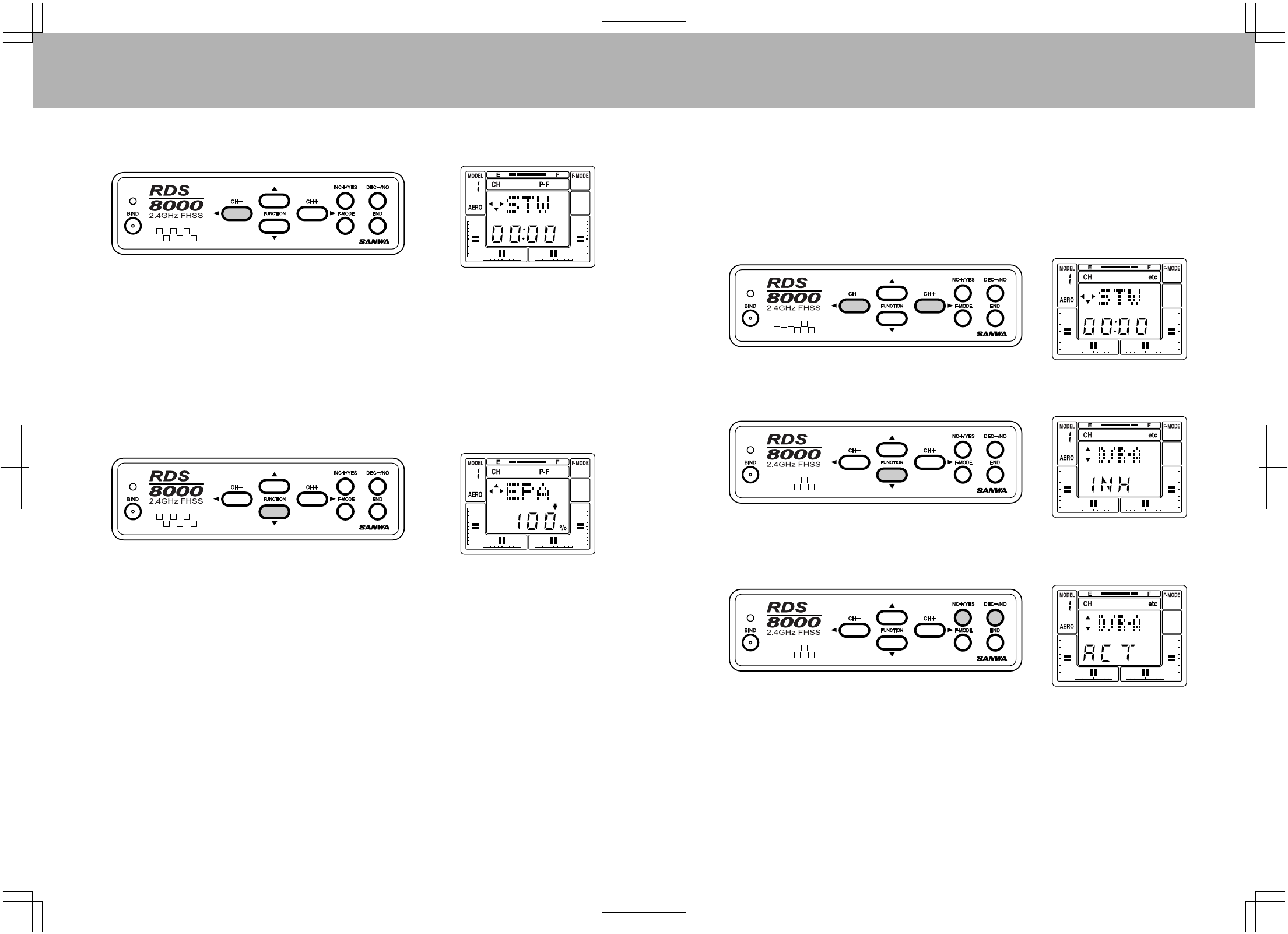
Pressthe(CH–)keytoselectP-FontheChannelindicator. ALARMS
D/R-A(DUALRATEALARM)
THROTTLESTICKHIGH
TheRDS8000offersan“ALARM”functiontowarnyouifyouturnyourtransmitteronwhileaDualRateSwitch
isactivated,andanothertowarnyouifyouturnthetransmitteronwhiletheThrottleStickisinanyposition
otherthanFull-Lowthrottle.TH-Hi!WillbedisplayedontheLCDscreenuntilyouplacetheThrottlestickin
thefull-lowposition.
ToactivatetheD/R-A(DualRatealarm),pressthe(CH–)orthe(CH+)keytoselect“etc”ontheChannel
indicator.
PresstheFUNCTIONdownkeyseveraltimestoscrolldownthemenuitemsandselecttheD/R-Ascreen.
Next,presseithertheINC+/YESortheDEC-/NOkeytosetD/R-AtoACTive.
IfaDualRateswitchisONwhenyouturnONthetransmitter,anaudiosignalof3beepswilloccur
approximatelyevery15secondsuntilyouturnoffadualrateswitch.
YoucanturnofftheDualRatealarmbypressingeithertheINC+/YESortheDEC-/NOkeytochange
D/R-AtoINHibit.
NotethattheHigh-ThrottleStickalarmisalwaysactive.
NOTE:TheRDS8000transmitterwillalsosoundanalarmifthepowerswitchisleftonwithoutany
movementofthecontrolsforaperiodoftimethatexceeds15minutes.ThescreenwillshowPWR!.
UsetheFUNCTIONdownkeytoscrolldowntoFLAPEPA(endpointadjust).Notethatthedefaultsettingis
+100%.Therangeofadjustmentisfrom0to150%.PresseithertheINC+/YESortheDEC-/NOkeyto
changethevalueofthefunction.ThethreepositionFLAP/FL-ELswitchwhichislocatedonthetoprightof
thetransmitteractivatedFlaperons.ThenormalpositionforFlaperonsatneutralpositioniswiththeswitch
towardsyou.NotethattheLeftAileronchannelmustbepluggedintoChannel2ofyourreceiverandthe
RightAileronintochannel6.TodisabletheFLAPswitch,setallthreeoftheFLAPEPA'sto0%.
UsetheFLAPTRM(trim)functiontofinetuneflapoperation.NotethatFLAPTRIMwillaffectallthreeFLAP
EPA's.
4948
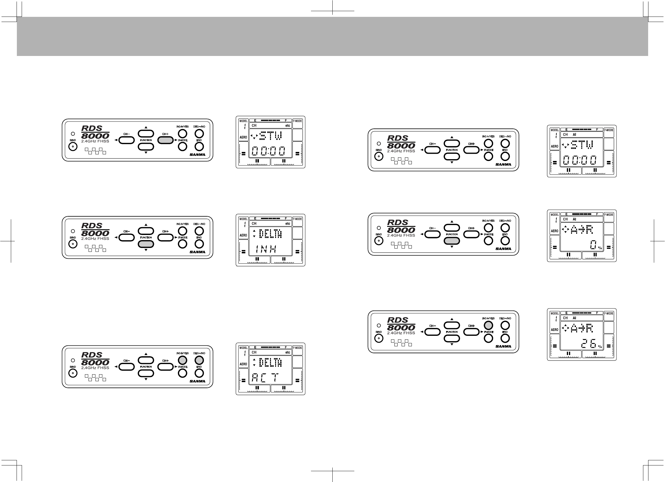
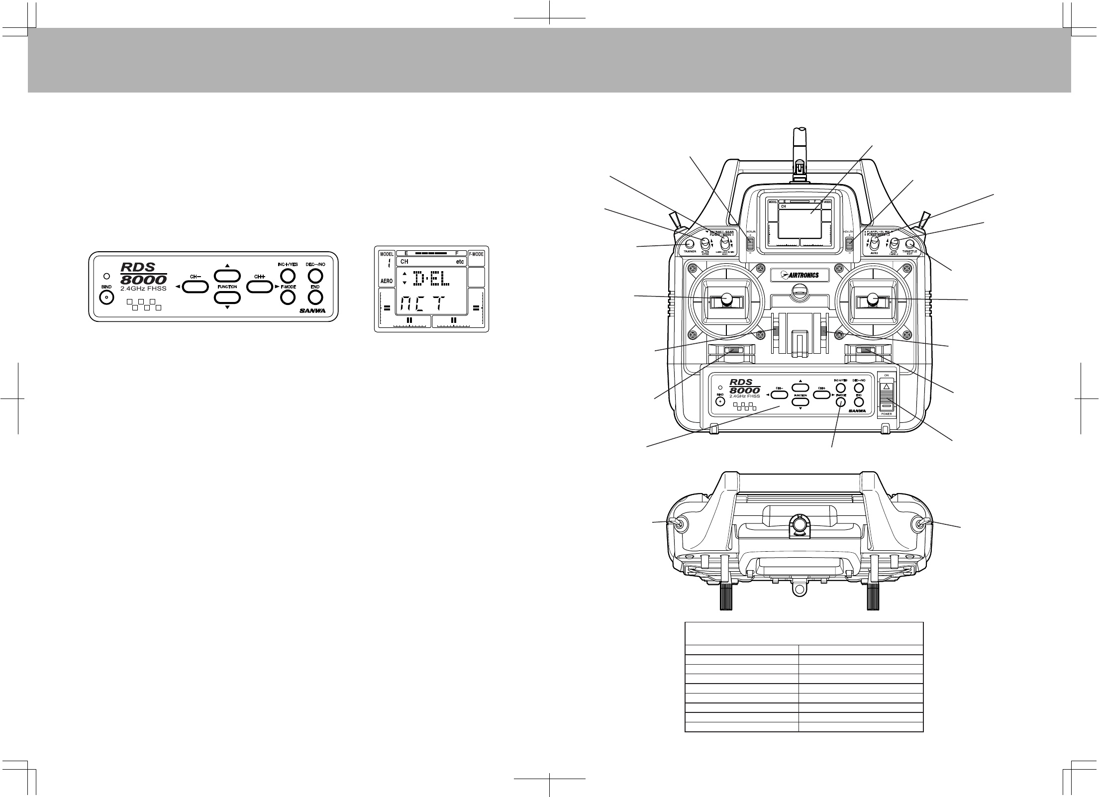
DELTA(ELEVONS)
DELTAmixcanbeusedinaflying-wingtypemodeltoprovideELEVONcontrol,wheretheelevatorand
aileronfunctionsarecombined.
ToaccesstheDELTAfunction,useeitherthe(CH–)orthe(CH+)keytoselecttheSTWscreen.
PresstheFUNCTIONdownkeytoscrolldowntotheDELTAscreen.
NowpresstheINC+/YESkeytochangethedisplaytoACT(Active).NotethatyoucannothaveFLAPE
(Flaperon)ActivewhenDELTAisActiveandviceversa.WhenDELTAisActive,youwillhavetwochannels
assignedforELEVONcontrol.Plugthesetwoservosintochannels#1and#2ofyourreceiver.Thetwo
servoswillnowrespondtomovementoftheelevator/aileroncontrolstick.EndPointAdjustmentsforelevator
andaileroncanthenbemadefortheamountofthrowrequired.
PresstheENDkeytoreturntotheSTWscreen.
A>R(AILERON-RUDDERMIX)
TheRDS8000providesthecapabilitytoprogramyouraircraftsothatAileronstickdeflectionwillalso
causetherudderservotorespondinthesamedirection,(rightaileron=rightrudder).Thisautomatic
coordinationofrudderwithaileronisusefulinmanyhigh-wing/scalemodelsthatsufferfromadverseyaw
withaileronapplication.Notethattherudderservowillstillrespondtorudderstickmovementaswellas
withaileronstickmovement.
TouseA>R(aileron-rudder)mixing,firstaccesstheAL(aileron)channelontheChannelindicator.
Next,presstheFUNCTIONdownkeytoselecttheA>Rdisplay.
PresstheINC+/YESkeytoadjusttheamountofmixingthatwilloccur.
YoucannowactivatetheAL>RUmixswitch,locatedabovethethrottle/rudderstickassembly,toturn-onor
offtheAL>RUmixfunction.PresstheINC+/YESandDEC-/NOkeyssimultaneouslyifyoudesiretoreset
A>RUto0%.
5150
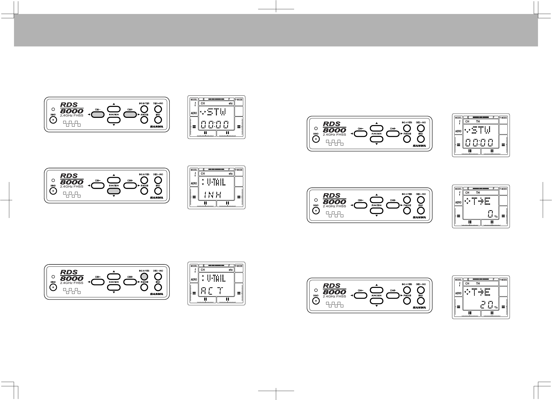
V-TAIL(RUDDER-ELEVATORMIX)
TheRDS8000transmitterhastheabilitytocontrolsailplanesorpoweredmodelsthatuseaV-Tailcontrol
system.Intheseaircraftthetwotailcontrolsperformbothaselevatorsandasrudders.Twoservosandtwo
channels(receiverchannels#1and#4arerequiredforV-Tailoperation).
ToselecttheV-Tailoperation,firstpresseitherthe<CH-ortheCH+>keytoaccessthe“etc”channel
indicator.
Next,presstheFUNCTIONdownkeytoscrolldowntotheV-TAILdisplay.
PresstheINC+/YESkeytoseethefollowingscreenwhichwillactivatetheV-TAILfunction.Ifyoupressthe
DEC-/NOortheINC+/YESkeyyoucantogglefromINH(Inhibit)toACT(Active).YoucanusetheRudder
andElevatorServoRev(Reverse)andEPA(EndPointAdjustment)functionstofinetuneyourset-up.
YoumayusetheAileron>RuddermixingfunctiontoallowoperationoftheV-Tailrudderswiththerightaileron
controlstick.SeeAL>RUmixing,page49.
T>E(THROTTLE-ELEVATORMIX)
TheRDS8000allowsautomaticadjustmentofElevatortrimasyouadvanceorretardthethrottlestick.This
isavaluableoptionasmostsailplanesneedachangeinpitchtrimwhenflapsaredeployed.Bymakingthis
adjustmentwithanelectronicmixer,thepilotdoesnothavetoaltertheelevatordigitaltrimseachtimeflaps
areused,andthusdoesnothavetore-trimtheelevatorsfornormalflight.Thisfeaturecanalsobeusedon
anengine-poweredmodeltomakesmallelevatortrimcorrectionsaspowerisappliedorreduced.
TousetheT>E(Throttle-Elevator)mix,presseitherthe(CH–)or(CH+)keytoselectTHontheCHindicator
screen.(NotethatyoumustbeontheSTWscreentomovehorizontallyacrosstheentireCHindicatorscreen).
PresstheFUNCTIONdownkeytoseethefollowingT>Escreen.
PresstheINC+/YESortheDEC-/NOkeytosetavalueforT>Emixing.Therangepossibleisfrom–100%
to+100%.Fornowinthisexample,presstheINC+/YESkeytoinsertavalueof20%fortheT>Emix.
Flighttestingwillalwaysberequiredtodeterminetheoptimumamountofmix.
PresstheINC+/YESandDEC-/NOkeyssimultaneouslytoresetT>Emixtothedefaultvalueof0%.
5352
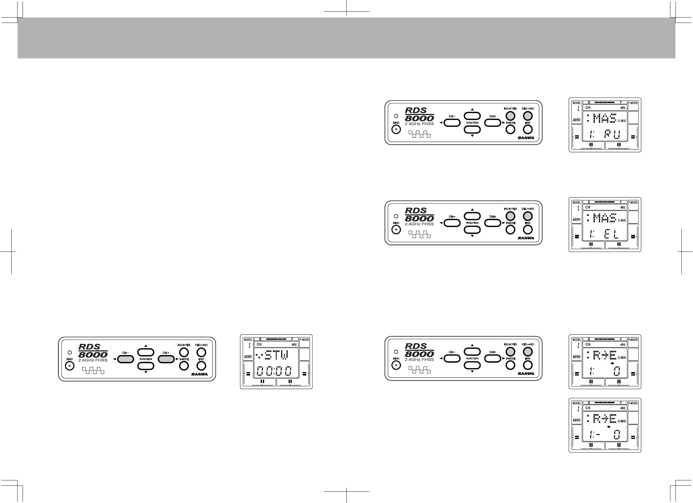
COMPENSATIONMIXERS(C-Mix)
TheRDS8000hastwocompensationmixerstohandleadvancedmixingneeds.Theseareinaddition
tothe
predefinedmixers.
ACompensationMixerallowsonetransmittercontrolinputtoaffecttwoflightfunctions.
AcommonmixwouldbeAilerontoRuddertoachievecoordinatedturnswithoutmovingtherudderstick.
However,theRDS8000providesapredefinedmixerforthisfunction.
Pressthe(CH+)keytomoveacrosstheCHindicatorandaccessthe“etc”screen.NextpresstheFUNCTION
downkeyandlocatethefollowingscreennamesinorder:
MAS1:EL=(C-Mix#1Masterchannel)exampleEL“Elevator”
SLV1:EL=(C-Mix#1SlaveChannel)exampleEL“Elevator”
E>E1:0%=(C-Mix#1mixingpercentage)Adjustfrom+150%to-150%example“ElevatortoElevator”
MAS2:EL=(C-Mix#1Masterchannel)exampleEL“Elevator”
SLV2:EL=(C-Mix#1SlaveChannel)exampleEL“Elevator”
E>E2:0%=(C-Mix#1mixingpercentage)Adjustfrom+150%to-150%example“ElevatortoElevator”
(AIRCRAFT)
BothC-Mix1andC-Mix2areoperatedbyoneswitchlocatedonthefrontupperleftsideofthetransmitter
andismarkedinredlettering.
(HELICOPTER)
BothC-Mix1andC-Mix2canbeturnedonandoffbyusingtheslideswitchlocatedonthefrontupper
rightareaofthetransmittermarkedinblueletteringC-Mix1,2.
Thefollowingexampleuse,C-Mix1tomixRuddertoElevatorasmaybeneededforknifeedgeflight.
Startbypressingthe(CH+)keyuntilyoureach“etc”.
NowusetheFUNCTIONdownkeyuntilyoureachthe(MAS1:)screen.NextusetheINCorDECkeysuntil
theRU(rudder)isselected.ThiswillbeyourMasterchannel.
NextpresstheFUNCTIONdownkeyoncetoselect(SLV1:)screen.NowusetheINCorDECkeysuntilyou
reachEL(elevator).ThiswillbeyourSlavechannel.
NextpresstheFUNCTIONdownkeyoncetoselect(R>E1:)screen.
BymovingtheRudderstickyouwillseethearrowindicatorsonthescreenchangedirectionsaccordingtothe
directionyoumovethestick,leftandright.YoucansettheC-Mixforbothdirectionsindependently.For
example,whenyouareinaknife-edgeandyougiveitrightrudderbuttheplanepullstothetopoftheaircraft
youcansimplymovedthesticktotherightandpresstheINCorDECkeysandobservetheelevatormovement.
Ifincreasingthenumbermovestheelevatorinthewrongdirection,youcandecreasethenumberintothe
negativesidetochangethedirectionofthecompensation.Onlyuseasmallamountofcompensationatfirst.
Youcansettheleftcompensationinthesamemanorifanycompensationisneeded.
WhentheC-Mixpercentagesinbothdirectionsareat“0”,therewillbe
nocompensationmixing.
5554
Thisfunctioncausestheflapstodeploywhentheelevatorcontrolstickismovedupordown.Itcanbeused
withaseparateflapservowithanoutputonthereceiverschannel#6orasflaperonswithtwoaileronservos
onchannel#2and#6.Thisfunctionismostcommonlyusedforaerobaticmodelswheredeployingflaps(or
flaperons)withelevatorcontrolmaketightercornersonmaneuverssuchasthesquareloop.Inordertouse
thisfunctionwiththetwoaileronservooptionyoumustfirstactivatetheFLAPERONfunction.Toactivate,
movethechannelselectorbypressingtheCH+keyuntilyoureach“etc”.NowpresstheFUNCTIONDOWN
keyseveraltimestoreachthe“FLAPE”screenandusetheYESorNOkeystoactive.PresstheENDkey2
timestoreturntotheMainscreen.
NOTE1:BASICmustbeturnedOFFforthisfeaturetooperate.
NOTE2:Flapswitchmustbeinthedefaut“UP”position.WhenactivatingtheFLAPEfunction,ifboth
servosmoveoffcenterwhenactivatingtheFLAPEfunctionthenmovetheflapswitchdown.Thiswillkeep
thecenteringoftheservoscorrect.
NextpresstheCH+keytomovetothe“EL”indicator.PresstheFUNCTIONdownkeyuntilyoureachE>F
0%screen.Nowyoucanaddelevatortoflapamount.Adjustmentisfrom0to100%.
CAUTION:
OnceyouactivatetheE>Fmixerbysettingavalue,itwillbeactiveatalltimesandtheaircraftwillrespond
toallcontrolinputssinceyoucannotturnitonoroffwithaswitch.YoucanuseaCompensationMixer
featuretouseaswitchinstead.
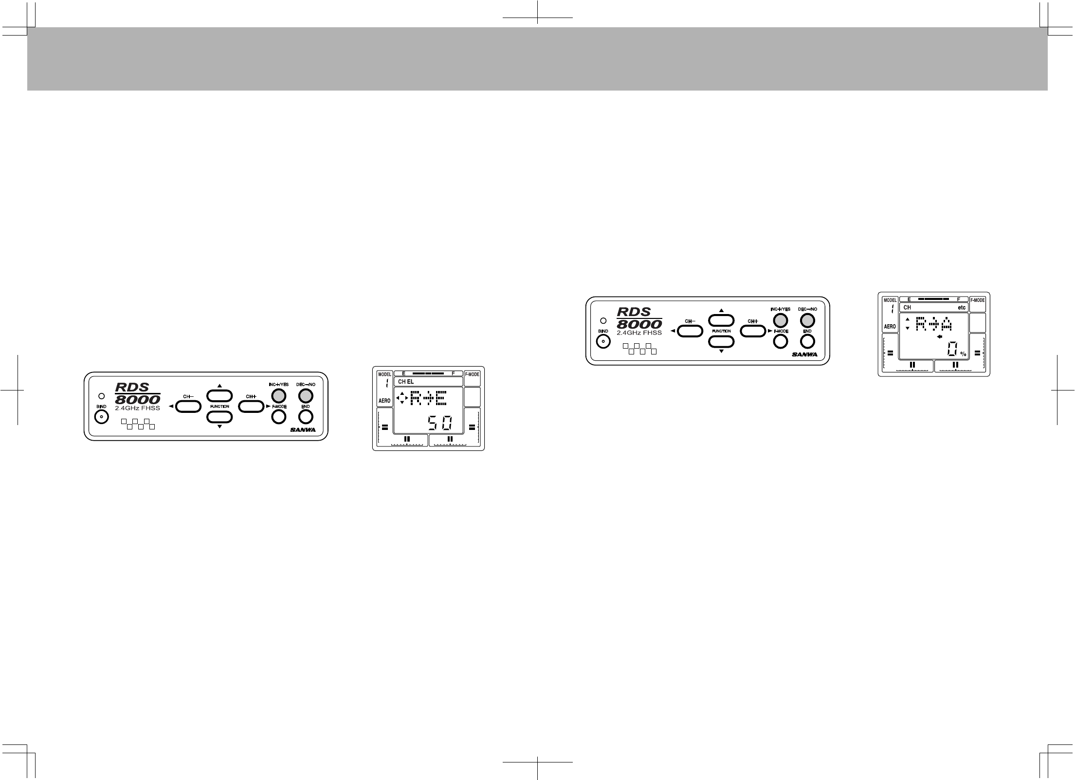
ELEVATOR-FLAPMIXING
Whenyouusethisfunctionyoucancausetheaileronstomoveleftandrightwhentheruddercontrolstickis
movedleftorright.Thepurposeofthismixeristoallowonetransmittercontrolinputtoaffectflightfunctions.
Acommonusewouldbeinknife-edgeflightwhereyouneedasmallcorrectioninailerontopreventroll
coupling.Tosetupsuchamix,usetheCH+keytoselectRUontheCHindicator.
NextpresstheFUNCTIONdownkeyuntilyoureachR>A0%screen.Nowyoucanaddruddertoaileronmix.
Adjustmentisfrom100to-100%.
Youcansetbothleftandrightruddertoaileronmixseparately.Bymovingtherudderstickyouwillseetheleft
orrightindicatordisplayonthescreen.Forexampleyoucansetleftmixat20%andrightat-30%depending
onthedirectionyouneedforthemix.
NOTE1:BASICmustbeturnedOFFforthisfeaturetooperate.
CAUTION:
OnceyouactivatetheR>Amixerbysettinginavalue,itwillbeactiveatalltimesandtheaircraftwill
respondtoallcontrolinputssinceyoucannotturnitonoroffwithaswitch.YoucanuseaCompensation
Mixerfeaturetouseaswitchinstead.
RUDDER-AILERONMIXING
RUDDER-ELEVATORMIXING
Ruddertoelevatormixingisused,forexample,wheninaknife-edgeflight,astheaircraftpullstothebellyor
canopywhenrudderisadded.
5756
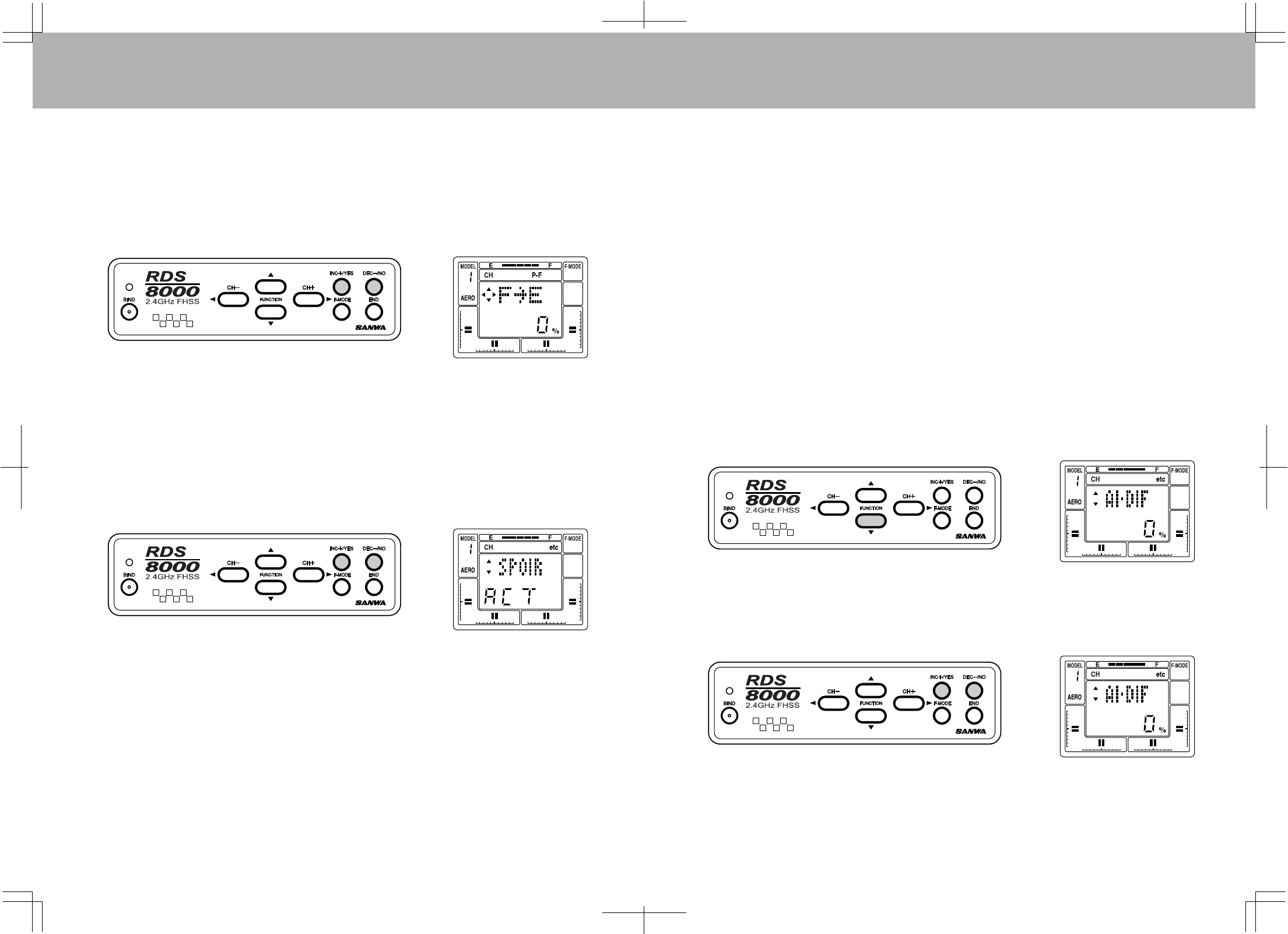
FLAP-ELEVATORMIXING
Thisfeatureisusedwhenyoudeploytheflaps.Normallywhenyoudroptheflapsonanaircraftitwillstartto
climb.Addingsomedownelevatorwillhelpreduceit.Adjustmentisfrom(100)to(-100)%.
NOTE1:BasicmustbeturnedOFFbeforethisfeaturewilloperate.
FromtheMainscreen,presstheCH+keyuntiltheP-FdisplaysintheCHscreenarea.Nowusethe
FUNCTIONdownkeytoselecttheF>Escreen.UsetheINC+/YESorDEC-/NOkeystosetthepercentages.
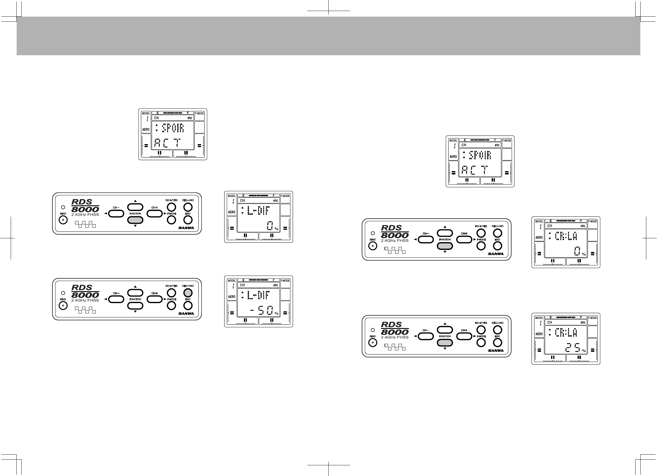
SPOIR(SPOILERON)
TheRDS8000hastheabilitytocontroldifferentfixed-wingaircrafttypes,includingconventionalsingle-aileron
servoordual-aileronservosonindividualchannelswithdifferentialadjustmentandwingswith
flaperons/spoilerons.TheSpoileronfunctionisnormallyusedwithsailplanes.
UsetheCH+keytomovetheCHindicatorto"etc".NowusetheFUNCTIONdownkeytodisplaytheSPOIR
screen.ActivatetheSPOIRbypressingtheINC+/YESorDEC-/NOkeys.
Inordertousetwoseparateaileronservochannelsand/orhaveelectronicailerondifferential,pressthe
INC+/YESkeytomaketheSPOIRreadACT(Active).Notethatitisonlypossibletoelectronicallyadjust
ailerondifferentialthrow,whenyouchoosetouseTWOCHANNELSforaileron,withaservooneachsideof
thewingdrivingthatwing’sservo.PressingtheINC+/YESortheDEC-/NOkeywilltogglethefunction
between“INH”and“ACT”settings.
WhenSPOIRisACTIVE,youwillhavetwochannelsassignedtotheaileron/spoileronfunction.Plugthese
servosintochannels#2and#6ofyourreceiver.Notethatbothservoswillrespondequallywhenyoumove
theaileronstickonthetransmitter.
IfAL-DIF(AileronDifferential)issetto0%,theservoswillmoveequallyinresponsetoleftandright
transmitteraileronstickmovement.IfavalueisinsertedforAL-DIFwhenusingtheSPOIRfunction,the
FLAPSTICK(throttle)willdeterminewhenAL-DIFbecomeseffectiveforasailplane.
AL-DIF(AILERONDIFFERENTIAL)
TheRDS8000hastheabilitytocontrolseveralaircraft‘wing’types,includingconventionalsingleaileronservo,
dual-aileronservosonindividualchannelswithelectronicdifferentialadjustmentanddelta(or“flyingwing”)
configurationswithElevons.ItisonlypossibletoelectronicallyadjustdifferentialwhenusingTWO
CHANNELSforailerons,withoneservooneachsideofthewingdrivingthatwing’saileron.TheAL-DIF
(ailerondifferential)functiononlyappliestotheDELTAandFLAPEmenufunctions.
Differentialreferstotheratioofup-to-downmovementofeachaileron.Manyaircraftneedmoremovement
fromtheupwarddeflectingaileronthanfromthedownwarddeflectingaileroninordertoeliminateunwanted
yawwhenaileronsareapplied.
NotethatdifferentialfortheSPOIR(Spoileron)function,usedwithsailplanesiscontrolledbytheL-DIF
(landingdifferential)function.AL-DIFhasnoeffectofSPOIR!
Thefollowingexample,assumesyouwanttohaveseparateservosforaileroncontrol.Sinceyoumusthave
twoservostoobtainelectronicdifferential,thefirstthingtodoisactivateFLAPE(Flaperons).Younowhave
twochannelsassignedtotheaileron/flaperonfunction.PlugtheseservosintoCHANNELS#2and#6ofyour
receiver.Notethatbothservoswillrespondequallywhenyoumovethetransmitter’saileroncontrolstick.
Ifyoudonotwanttheaileronstoactasflaps,selectP-HontheChannelindicator,anddisabletheFLAP
switchbysettingFLAPEPAto0%upanddown.
PresstheFUNCTIONdownkeytoselecttheAL-DIF(ailerondifferential)screen.
Next,presstheINC+/YESkeytosetavalueforailerondifferential.Inthisexamplethedifferentialissetto
50%.Thismeansthatthedownwarddeflectingaileronwillmovehalfasmuchasdoestheupward-deflecting
aileron.Thefinaladjustmentswillbedeterminedbyactualflighttesting.
Theabovedisplayshowstheamountofdifferentialthatwehavepresentlyprogrammed.Therangeof
adjustmentisfrom–100%to+100%.Defaultis0%.Ifthedifferentialyousetisinthewrongdirection,i.e.,
lessup-deflectionthandown-deflection,changethepolarityofthevaluethatyouprogrammedbyusingthe
INC+/YESorDEC-/NOkeys.
5958
L-DIF(LANDINGDIFFERENTIAL)
TheL-DIF(landingdifferential)functionenablestheaileronsofasailplanetobeeffectivewheneverboththe
leftandrightaileronsareraisedwhenCROWorSPOILERONareusedinlanding.Typicalthermalsailplanes
requireabouttwiceasmuchuptravelasdowntraveloftheaileronstoproduceacoordinatedturn.
TheRDS8000allowsyoutosettheamountofdifferentialailerontravelduringthelandingmode.TouseL-DIF
theSPOIR(Spoileron)functionmustbesettoActive.Seepage56andactivatetheSPOIRfunction.
Next,presstheFUNCTIONdownkeytoscrolltotheL-DIF(landingdifferential)screen.
Now,presstheDEC-/NOkeytosetavalueof–50%forL-DIF.
NotethattheapplicationofLandingDifferentialiscontrolledbythepositionoftheFLAP(throttle)stick.As
youbringthestickdownanddeployyourflaps,theaileronlandingdifferentialincreasestotheamountthat
youprogrammed.IntheaboveexamplewesetL-DIFto–50%.However,thepolarityofthesettingdepends
onyourspecificservoinstallation,i.e.,thesettingcaneitherbepositiveornegative.
Moveyouraileronstickfromsidetosideandobservethechangeintheratioofuptodowntravelasyou
bringtheFLAPstickdown.
TherangeofadjustmentofL-DIFisfrom–100%to+100%.ToresetL-DIFtothedefaultvalueof0%,press
boththeINC+/YESandDEC-/NOkeyssimultaneously.
FlighttestingwillberequiredtodeterminetheoptimumsettingforyourL-DIF..
CR:LA(CROWLEFTAILERON)
CR:RA(CROWRIGHTAILERON)
Inlandingmode,theflapsprovidealargeamountofbothliftanddrag.Thiscausestheplaneto
flyveryslowlyanddescendgently.Onverylightsailplanestherateofdescentmaybesoslowthattheplane
tendsto“floatrightpast”thelandingspot.CROW(bothaileronsup)addsquiteabitofdragwhiledecreasing
lift.Thisincreasestherateofdescent(steepenstheglideslope)andimprovescontrollability.Theamountof
CROWthatisusedshouldbeadjustedtosuitpersonalpreference.Ingeneral,higherwing-loadingsailplanes
requirelessCROWbecausetherateofdescentwillprobablyalreadybehighenough.
InordertoprogramtheCROWfunctionyoumusthavepreviouslyselectedtheSPOIR(Spoileron)functionand
setittoActive.
PresstheFUNCTIONdownkeytoselecttheCR:LA(Crowleftaileron)screen.
Next,presstheINC+/YESkeytoprogramavalueof25%.HerewehavesetCROWfortheLeftAileronat
25%.TheLeftAileronnowwillraise25%ofitstravelupwardwhiletheflapsdeploydownwardwhileinthe
LandingMode.TheLandingMode,FlapdeploymentandCROWareallcontrolledbythepositionofthe
FLAP(throttle)stick.TherangeofadjustmentforCROWis+100%to–100%.Thedefaultvalueis0%.
Now,presstheFUNCTIONdownkeytomovedowntotheCR:RA(CROWrightaileron)screen.Pressthe
INC+/YESkeytosetitat25%.NowbothaileronsrespondidenticallytotheCROWcommand.
6160
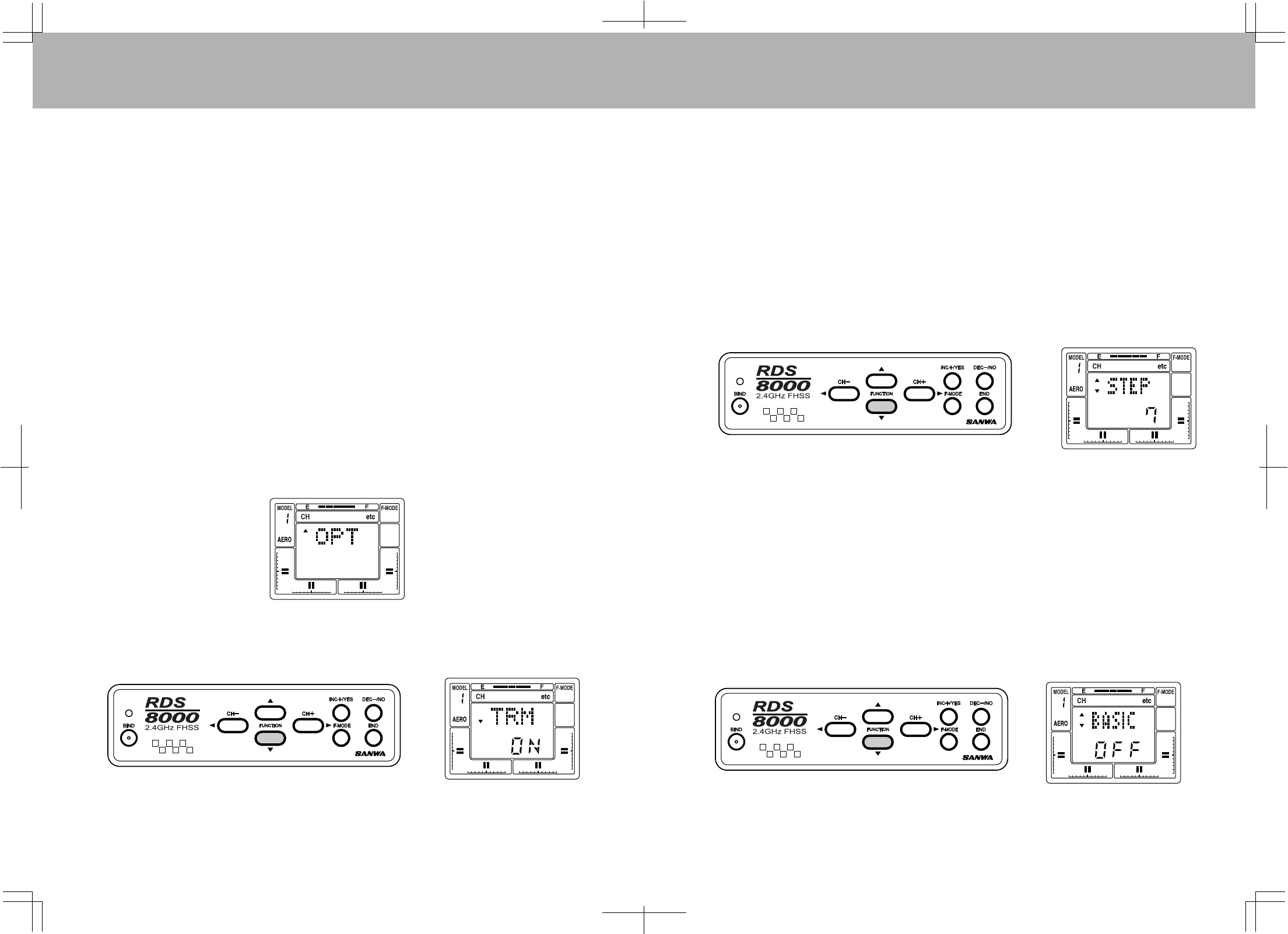
OPTIONMENUSCREEN
IntheadvancedprogrammingyouhavetheabilitytoturnoffunusedprogrammingscreenswiththeOPTION
MENUSCREEN.Thisisveryusefulandconvenientwhenoneofyourmodelsonlyrequiressome
features.Forexample,oneaircraftisusedasatrainerandyoudonotneedtouseanyC-MIX,CROW,
AI-DIF,DELTA,V-TAIL,youcangototheOPTscreenandturnthemoffsotheywillnotdisplayinthenormal
programmingscreens.Ifyoudecidelaterthatyouwanttouseafeatureyouhaveturnedoff,youcanat
anytimeusetheOPTtoturnthefeaturebackon.
Turningoffthefeatureonlyremovesitfromtheprogrammingscreen.Itwillnot,however,turnoffthe
feature.Example,youhadactivatedyourFLAPEforFlaperonsandthenintheOPTscreenyou
turnedFLAPEoff.YourFlaperonswillstillbeactivebutyouwillnotseetheFLAPEscreeninthe
programmingmenu.
Thisfeatureisbestusedonanaircraftorhelicopterafteryouhavesetupyour“needonallthetime”
features.Forexampletheswashplatetypeforahelicopter,onceyouselecttheswashplatetype
youcanthenturntheswashplatetypescreenoffbecauseyouhavenoadjustmentsinthatscreen,
andbyturningthescreenoffyouwillnotmistakenlychangetheswashplatetype.
Beforeturningoffanyunused-featurescreens,makesuretheyareatthedefaultsettingordonothaveany
affectonacontrolsurface.
UsetheCH+keytomovetothe"etc"intheCHareaofthemainscreen.NextusetheFUNCTIONdownkey
untilyoureachtheOPTscreen.NowpresstheYESkey,theOPTwillnowflash3times.Nowyoucanuse
theFUNCTIONdownkeytoviewallthefeaturescreensthatcanbeturnedoff.Turningthefeatureonoroff
isdonebyusingtheYESorNOkeys.AfterselectingYESorNO,youcannowpresstheENDkeytoexitout
oftheOPTscreen.PressingEND3timeswillbringyoutothemainscreen.
NOTE1:
NOTE2:
STEP(TRIMSTEP)
AnytrimthatyousetwhileyourmodelisinflightbyuseoftheDigitalTrimkeyswillautomaticallybestored
inmemoryforthatspecificchannelandmodel,providingthatTRMwaspreviouslyturnedOFFinthe
OPTIONSsectionoftheprogram.
TheTrimvaluein%thatyousetduringflightisshownontheTRMscreenforeachChannel.Inaddition,
therearebargraphindicatorsonthescreenthatshowhowmuchtrimhasbeensetforElevator,Aileron,
ThrottleandRudderchannels.
TheamountthattheTrimFunctionchangeseverytimeyoupresstheDigitalTrimkeyi.e.,theTrimAuthority,
isvariable,anditcanbesetbytheuser.Forinitialtestflightsofyourmodelitisrecommendedthatitbeset
atavalueof7toallowformaximumabilitytotrimyourmodel.Afteryourfirstflightandyouraircrafthasbeen
trimmed,youcanthenprogramamorepreciseadjustmentfortrimauthoritybyusingtheSTEPfunction.
TochangetheTrimAuthority,accesstheSTWscreenforELaspreviouslyexplained.PresstheCH+key
severaltimestoselectthe“etc”screen.NowpresstheFUNCTIONdownkeyuntilyoufindthefollowing
screenthatindicatesSTEP.
IfyouwanttochangetheTrimAuthoritytoalessernumbertomaketheDigitalTrimkeyslesssensitivefora
finersetting,presstheDEC-/NOkey.Ifyouwanttoincreasethesensitivitytoobtainagreaterchange,
presstheINC+/YESkey.ThemaximumvalueofTrimAuthorityis15andtheminimumvalueis0.
CAUTION:Ifsettozero,youdonothaveanyTrimcapability.
.
BASICMENU
BydefaulttheBASICaircraftandhelicopterprogrammingmenuareon,givingyouthebasicfeatures
includedintheRD8000.ByturningBASICOFF,youareturningontheADVANCEDaircraftorhelicopter
programmingmenu.
ToturnBASICOFF,presstheCH+keyuntilyoureach“etc”intheCHareaonthemainscreen.Nowpress
theFUNCTIONdownkeyuntilyoureachtheBASICONscreen.PresstheYESorNOkeytoturnonthe
Advancedprogrammingmenu.PresstheENDkey2timestoreturntothemainscreen.
6362
DUALELEVATORMIXING
YourRDS8000offersDUALELEVATORMIXINGthatallowsyoutouseaseparateservoforeachelevatorhalf.
YouuseChannels1and7onthereceiverforthisfeature.
ActivatingtheDualElevatorfeaturewillautomaticallydisableyourAUX-1channel7switchandwillallow
channel7tobeusedwiththeelevatorstick.
YouwillbeabletosettheEPA,REV,CENTERandFAILsafeseparatelyforbothchannels.UseChannel1
foryourleftelevatorandusechannel7foryourrightelevator.
RDS8000Transmitter-HELICOPTER
TrainerSwitch
Gyro
AUX1
DigitalHoverPitchINC/DEC
DigitalHoverThrottleINC/DEC
LiquidCrystalDisplay
Throttle(U/D)
Rudder(L/R)
ThrottleDigitalTrim
RudderDigitalTrim
PanelInputKeys
AUX-2
C-Mix1,2
ThrottleCutSwitch
MainPowerSwitch
FlightModeSelector
FlightMode3
(SeePage77to
changeF.M.switch
locations)
FlightModeN,1,2
(SeePage77to
changeF.M.switch
locations)
ElevatorDigitalTrim
AileronDigitalTrim
Elevator(U/D)
Aileron(L/R)
92824ZReceiverChannelAssignments
ReceiverSlotNumber
1
2
3
4
5
6
7
8
PluginServoFor:
Elevator(F/A)Cyclic
Aileron(L/R)Cyclic
Throttle
Rudder(TailRotor)
Gyro
CollectivePitch
AUX1
AUX2/Battery
AUX-1andAUX-2:
AUX-1.PresstheCH-keytoselectCH7ontheChannelIndicator.WhenAUX-1(Channel7)isnotused
forDualElevator(D-EL)controlandisinhibited,thefunctioncanbeturnedonandoffbytheAUX-1switch
whichislocatedabovethethrottlegimbal.ServoReverse,Center,andEPAadjustmentscanbemadeatthe
Channel7menu.NotethatChannel7canbemixedwithanyotherchannelusingtheCompensationMixers.
AUX-2.PresstheCH-keytoselectCH8ontheChannelIndicator.TheAUX-2,Channel8menuprovides
adjustmentsforServoReverse,Center,andEPA.Channel8canbemixedwithanyotherchannelusingthe
CompensationMixers.
6564
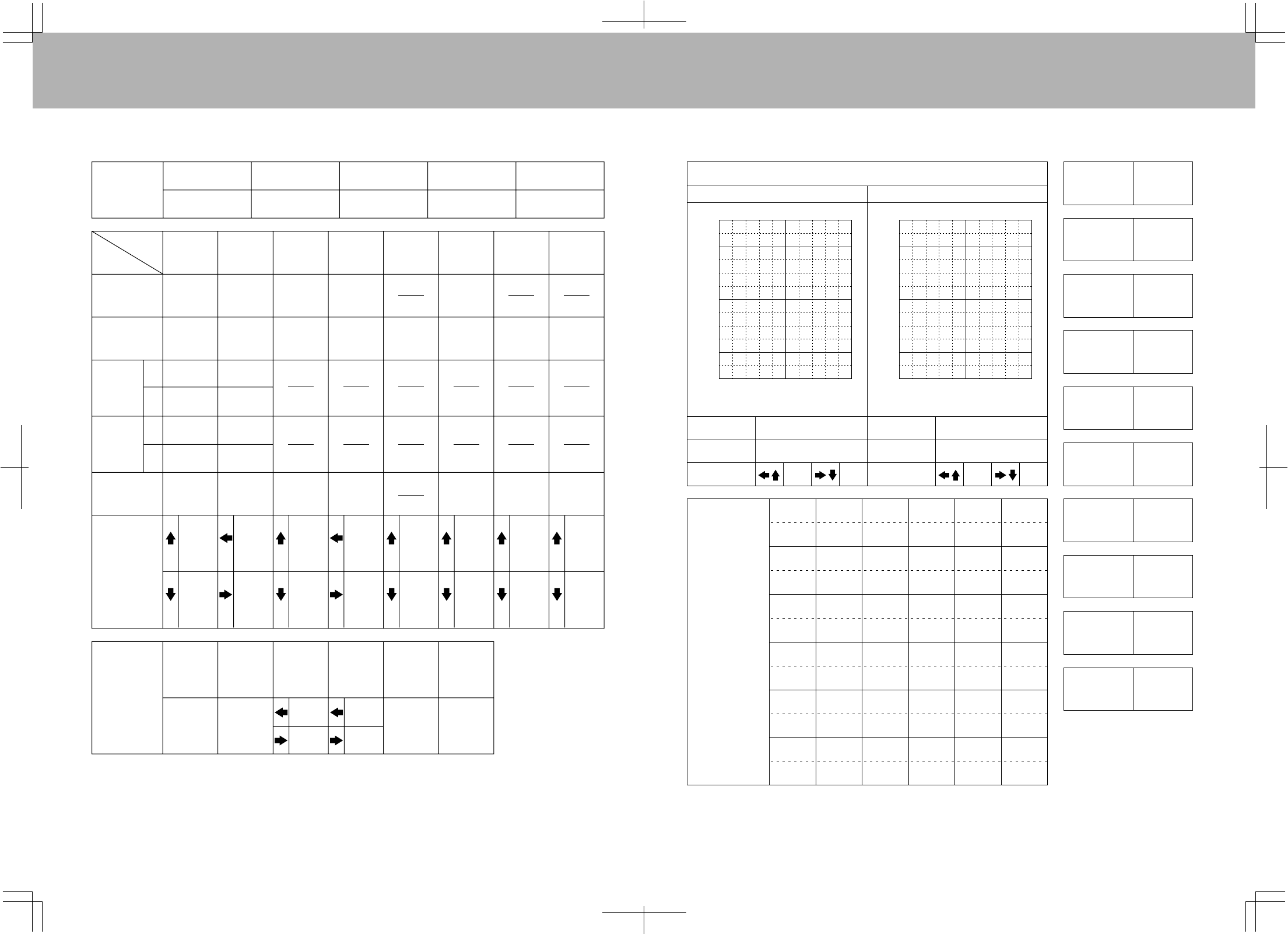
(RxChannel) CH EL AL TH RU G P/F 78etc
STW STW STW STW STW STW STWSTWSTW
REV REV REV REV REV REV REVREVM-SL
D/R D/R CNT D/R GYR CNT CNTCNTTYP
CNT CNT EPA CNT EPA EPAEPARST
EPAEPA CV-PH EPA CV-PH BASICON
CV-P3 RV.H CV-P3
CV-P2 RV.M CV-P2
CV-P1 RV.L CV-P1
CV-PL CV-PL
(RxChannel) CH EL AL TH RU G P/F 78etc
STW STW STW STW STW STW STWSTWSTW
TRM TRM TRM TRM REV REV REVREVM-SL
REV REV REV REV GYR CNT CNTCNTNAM
D/R D/R CNT D/R EPA EPAEPAMAS1
EXP EXP EPA EXP CV-PH
CNTCNT CV-PH CNT CV-P3 E>E1
EPA EPA CV-P3 EPA CV-P2 MAS2
CV-P2 RV-H CV-P1 S
SLV1
LV2
CV-P1 RV-M CV-PL E>E2
CV-PL RV-L STWset
T-CUT INTset
STEP
TYP
SW-R
CPY
RST
CLK
DTM
SWH
BASICOFF
OPT
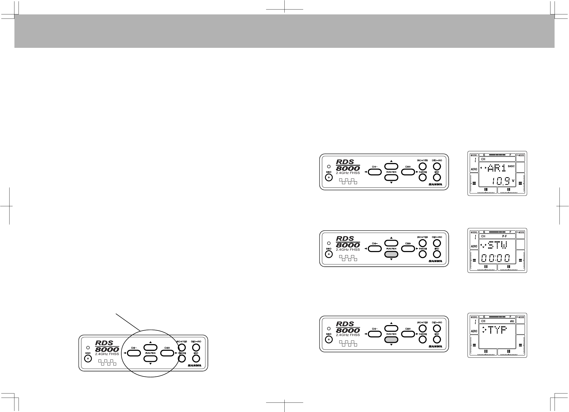
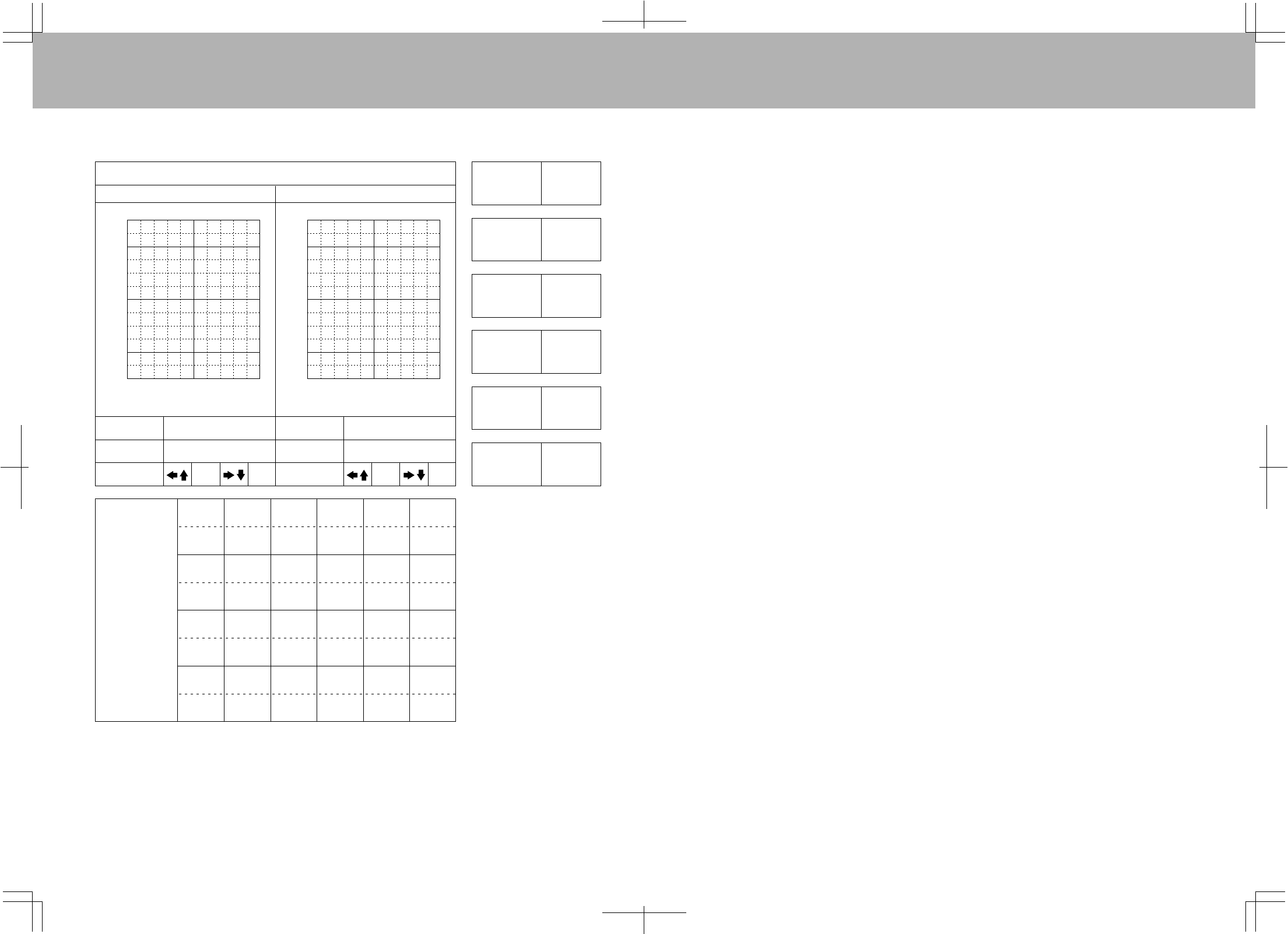
NOTE:Usethe(CH-)and(CH+)keystomovehorizontallywithinthesamefunction.
UsetheFUNCTIONUPandFUNCTIONDOWNkeystomoveverticallywithinthemenu.
ThesmalltrianglestotheleftofthefunctionthatshowsontheLCDscreenindicatesthedirectionthatyou
canmovehorizontallyandverticallyinthemenu.
Usethefourcenterbuttonsinthefunctionpaneltonavigatethroughthemenus.
(UP/DOWN/LEFT/RIGHT)
HELICOPTERBASICMENUSTRUCTURE
HELICOPTERADVANCEDMENUSTRUCTURE
PROGRAMMINGFORHELICOPTER
INITIALSET-UPOFTYP(MODELTYPE)
TheRDS8000transmitterisfactory-programmedforbothfixed-wingaircraft
andhelicoptermodels.Ifyoufly
onlyhelicoptermodelaircraft,youcanchangemodel’s1,3,5,7and9tohelicopter.
TurnthetransmitterpowerONandpresstheENDkeyuntilyoucometothedefaultmainscreen.Theinital
screenwillshowAR1whichindicatestheaircrafttypeaswellasshowingtheNiCdbatteryvoltage.
Pressthe(CH+)keytoscrollacrosstheCH(channel)indicatoronthescreento“etc”.
PresstheFUNCTIONdownKeyoncetoaccesstheTYP(modeltype)screen.
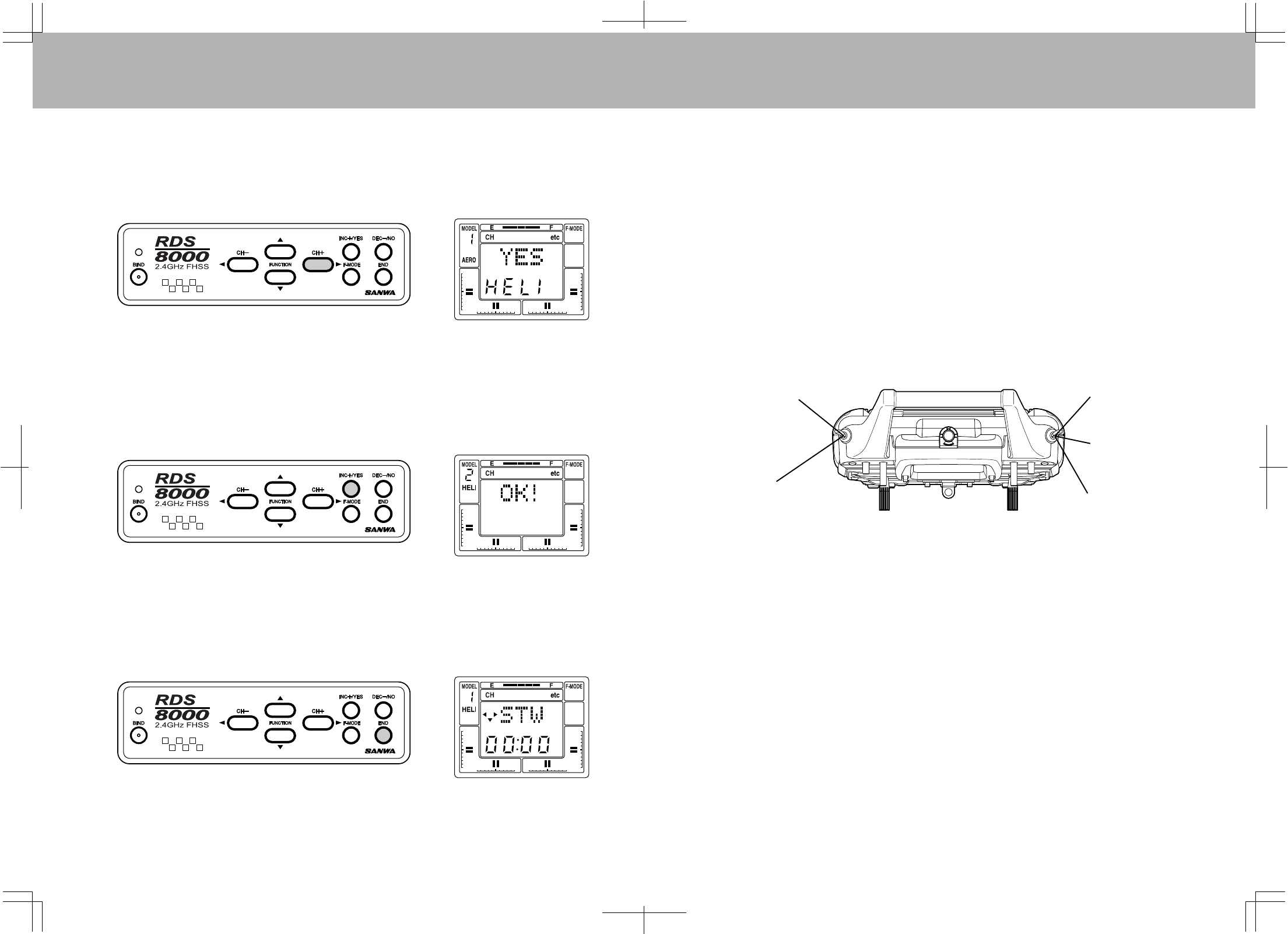
6766
Notethatoneofthesmalltriangularindicatorswillbeblinkingtoshowthatyoushouldpressthe(CH+)key.
Therefore,pressthe(CH+)keyandthescreenwillchangetoreadHELIwithaflashingYES.
Toconfirmthechangeofaircrafttype,presstheINC+/YESkey.ThescreenwillthenchangetoreadOK!
AsshownonscreenbelowtoindicatethemodeltypehasbeenchangedtoHELIfrommodel#1.Pressthe
ENDkeytwicetoreturntotheSTWscreen.
PresstheENDkeytwicetoreturntotheSTWscreen.Thesameprocedureasnotedabovecanbeusedto
changeModel#3,5,7,9fromAEROtoHELI.
PITCHCURVES(FLIGHTMODES)
TheRDS8000allowsyoutocustomizefourdistinctflightmodesforeachhelicoptermodel.
Thefourpitchcurves(flightmodes)availableforeachhelicoptermodelare:
N…………………………..SelectCurveN--NORMAL
1…………………………...SelectCurveOne–IDLEUP1
2…………………………...SelectCurveTwo–IDLEUP2
3…………………………...SelectCurveThree--HOLD
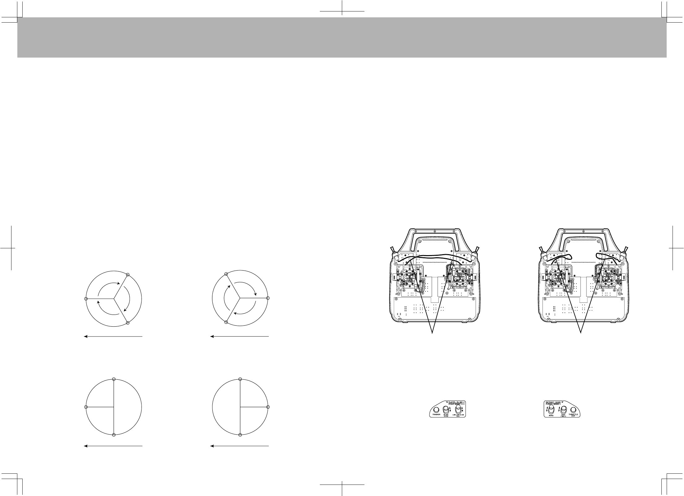
SelectingapitchcurveisdonebyactivatingthetwoFLIGHTMODEswitcheslocatedonthetopofthe
transmitter,asshownbelow.Thedefaultpositionsareasindicted.
NotethatBOTHF-MODEswitchesmustbepositionedtowardyoutoselectF-MODENORMAL.
CAUTION:FlightModes1,2and3.Ifeitheroneisactivatedwhenyouturnonthetransmitter,anaudio
alarmwillsound.Youmustalwaysbeawareofwhichflightmodeyouhaveselectedbeforestartingyour
engineorattemptingflight!
NOTE:Seepage77onhowtoreversethe2-positionand3-positionswitches.NormalHELIflyinginthe
U.S.A.hasthe3-positionswitchontheleftsideofthetransmitter.
F-Mode3orHold:
Switchpositioned
awayfromyou
F-ModeNormal:Switchpositioned
towardsyou
F-Mode2:
Switchpositioned
awayfromyou
F-Mode1:
Switchpositionedin
center
F-ModeNormal:
Switchpositioned
towardyou
ON
POWER
6968
Thepitchcurveforeachflightmodehasfivepointsthatcanbeadjustedtosuityourspecificneeds.Within
eachpitchcurvethesepointsarereferredtoasPH(highpitch),P3,P2,P1andPL(lowpitch).Therangeof
valuesanddefaultsettingsforeachisshownbelow.ToactivateP3andP1,presstheYESkeywheninP3or
P1screens.Tosetbacktodefault,pressboththeYESandNOkeysatthesametime.
CurvePoint
PH
P3
P2
P1
PL
PH
P3
P2
P1
PL
PH
P3
P2
P1
PL
Minimum
-25%
-25%
-25%
-25%
-25%
-25%
-25%
-25%
-25%
-25%
-25%
-25%
-25%
-25%
-25%
Default
100%
INH
50%
INH
0%
100%
INH
50%
INH
0%
0%
INH
0%
INH
0%
Maximum
125%
125%
125%
125%
125%
125%
125%
125%
125%
125%
125%
125%
125%
125%
125%
FLIGHTMODE
Normal
F.Mode1and2
F.Mode3orHold
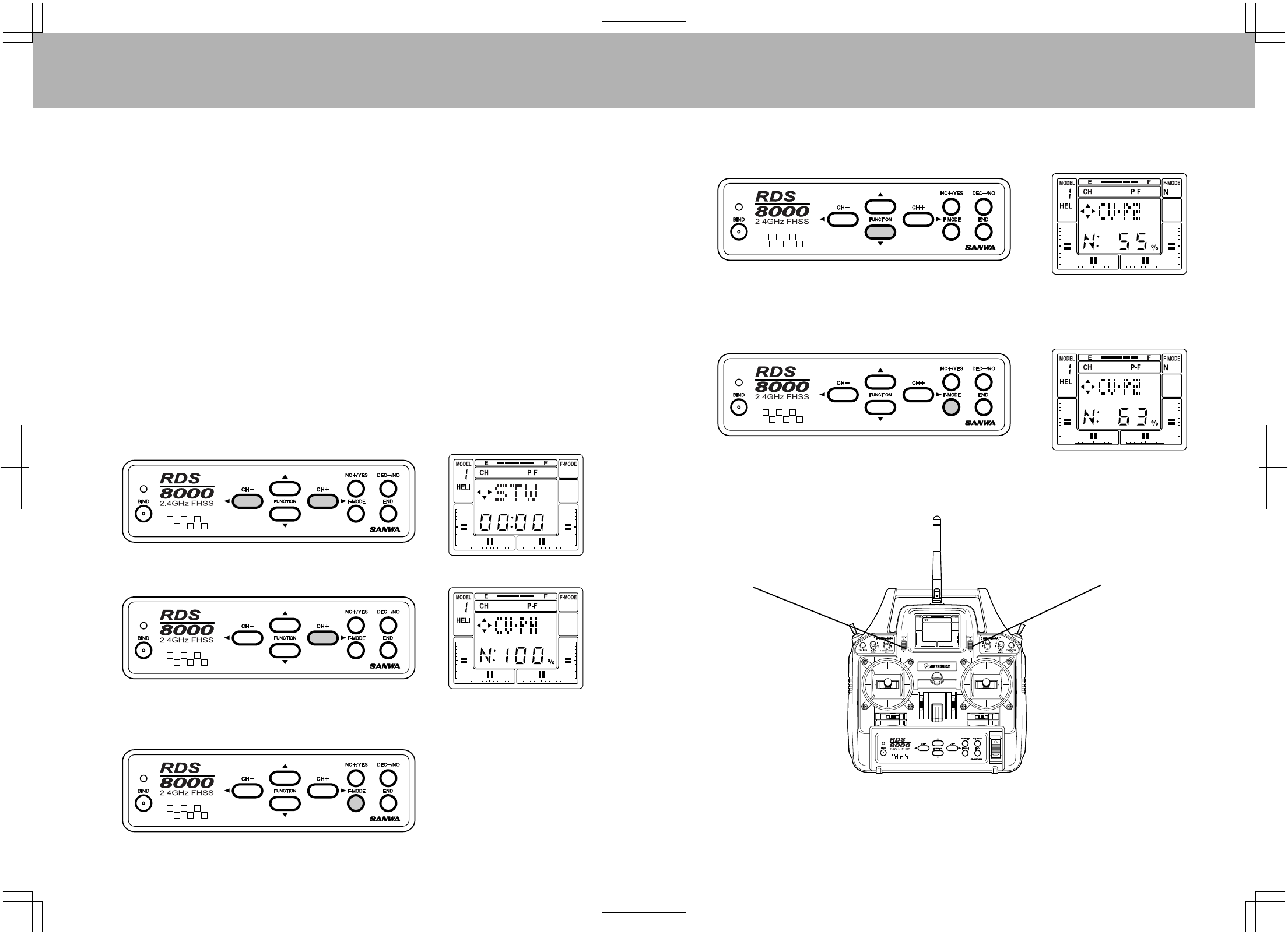
Toprogramyourpitchcurves,pressthe(CH–)or(CH+)keytoselectP-FontheChannelindicator.
Next,presstheFUNCTIONdownkeyandscrolldowntotheCV-PHscreen.
PresstheF-MODE(flightmode)switchtotogglethroughmodes1,2,3andNormal.
NowusetheF-MODEswitchtoselectthespecificflightmodetoadjust.Asanexample,ifyouwanttoadjust
CV-P2inNormalflightmode,presstheFUNCTIONdownkeytoselectCV-P2.Thedefaultvalueforthe
Normalflightmodeof55%willbeshown.
PresstheINC+/YESkeytosetanincreaseinvalueorpresstheDEC-/NOkeytosetalesservalue.Press
bothINC+/YESandDEC-/NOkeyssimultaneouslytoreturntothedefaultvalue.
InnormaloperationyouwillusuallysettheapproximateHoveringPitchwiththesoftwareinthePitch
screensthenadjustasneededforvariousweatherandflyingconditionswiththeHOV-PI(hoverpitch)
digitaltrimswitch.
HOV-TH+-
DigitalTrim
HOV-PI+-
DigitalTrim
FinetuningtheHoverPitchisalsoavailablebytheHOV-PTdigitaltrimswitchlocatedabovethethrottlestick.
NOTE:HOV-PIandHOV-THtrimsareusedonlyforadjustmentinflightmodeN(normal).
TheyhavenoaffectonFlightMode1or2.
7170
THROTTLECURVES(FLIGHTMODES)
Thethrottlecurveforeachflightmodehasfivepointsthatcanbeadjustedtosuityourspecificneeds.Within
eachthrottlecurvethesepointsarereferredtoasPH(highpitch)P3,P2,P1andPL(lowpitch).Therange
ofvaluesanddefaultsettingsforeachisshownbelow.ToactivateP3andP1,presstheYESkeywheninP3
orP1screens.Tosetbacktodefault,pressboththeYESandNOkeysatthesametime.
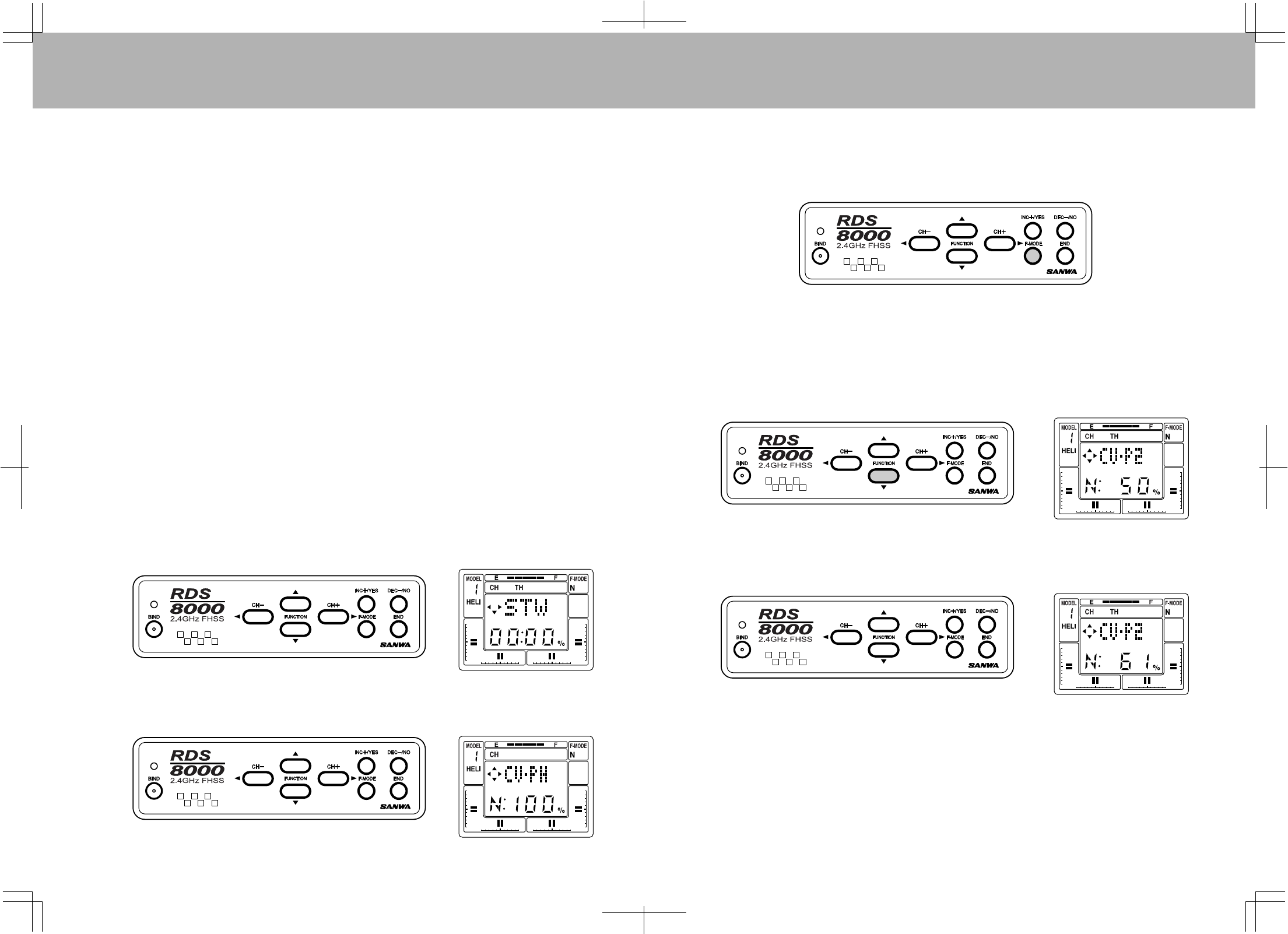
Toprogramyourthrottlecurves,pressthe(CH–)or(CH+)keytoselectP-FontheChannelindicator.
Next,presstheFUNCTIONdownkeyandscrolldowntotheCV-PHscreen.
CurvePoint
PH
P3
P2
P1
PL
PH
P3
P2
P1
PL
PH
P3
P2
P1
PL
Minimum
-25%
-25%
-25%
-25%
-25%
-25%
-25%
-25%
-25%
-25%
-25%
-25%
-25%
-25%
-25%
Default
100%
INH
50%
INH
0%
100%
INH
50%
INH
0%
0%
INH
0%
INH
0%
Maximum
125%
125%
125%
125%
125%
125%
125%
125%
125%
125%
125%
125%
125%
125%
125%
FLIGHTMODE
Normal
F.Mode1and2
F.Mode3orHold
NowusetheF-MODEswitchtoselectthespecificflightmodetoadjust.Asanexample,ifyouwanttoadjust
CV-P2inNormalflightmode,presstheFUNCTIONdownkeytoselectCV-P2.Thedefaultvalueforthe
Normalflightmodeof50%willbeshown.
PresstheINC+/YESkeytosetanincreaseinvalueorpresstheDEC-/NOkeytosetalesservalue.Press
bothINC+/YESandDEC-/NOkeyssimultaneouslytoreturntothedefaultvalue.
FinetuningoftheHoverThrottleisalsoavailablebytheHOV-THdigitaltrimswitchlocatedabovetheelevator
stick.
PresstheF-MODE(flightmode)switchtotogglethroughmodes1,2,3andNormal.
7372
REVOLUTIONMIXING
TheRDS8000providesforsettingRevolutionMixingforeachofthefourFlightModes.EachFlightModehas
itsowncurveforadjustingtailrotorpositioninresponsetothethrottle/collectivestickmovements.The
defaultsettingsforRV.H(RevolutionMixingHighPoint),RV.M(RevolutionMixingMidPoint),andRV.L
(RevolutionMixingLowPoint)areasfollows:
FLIGHTMODE
Normal
F.Mode#1
F.Mode#2
F.Mode#3
RV.H
20%
0%
0%
0%
RV.M
0%
-2%
-5%
0%
RV.L
-20%
-5%
-10%
0%
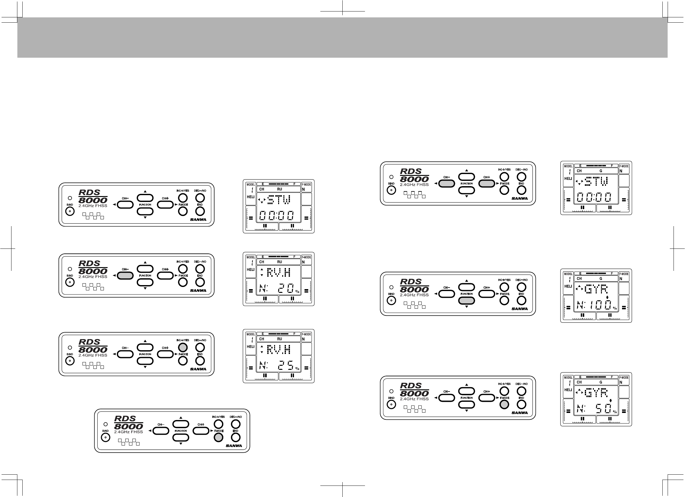
ToprogramRevolutionMixing,presseitherthe(CH–)or(CH+)keytoselectRU(rudder)ontheChannel
indicator.
Next,presstheFUNCTIONdownkeytoselectRV.H,whichistherevolutionmixinghighpoint.
UsetheINC+/YESorDEC-/NOkeytochangethedefaultvalueifyoudesiretodosoforanyofthethree
flightmodes.Inthisexample,wehavesetRV.HfortheNormalflightmodeto+25%.
ThesameprocedurecanbeusedtoinputvaluesforRV.MandRV.L.PresstheFlightModeswitchtoselect
thedifferentFlightModes.
GYROADJUSTMENT
TheRDS8000allowsyoutosettheGyrosensitivityofyourhelicopter’sgyroifithasthatcapability.Thegain
ofthegyrocanbeadjustedforallofthefourFlightModes2settingsforeach.Inthismannerthepilotcan
adjustthegyroforasuitablelevelofsensitivity(gain)foroneflightmode(forinstance,hover),andby
changingtoadifferentflightmodealterthesensitivityformoreorlessstabilization.Notethatyoumust
beusingagyrothatoffersremotesensitivityadjustment.
Presseitherthe(CH–)orthe(CH+)keytoselectG(Gyro)ontheChannelindicator.
Now,presstheFUNCTIONdownkeyseveraltimestoaccesstheGYR(gyro)screen.Thedisplaywilllook
likethefollowingscreenwhentheNormalflightmodeisselected.
Toadjustthegyrosensitivityforaspecificflightmode,presseithertheINC+/YESorDEC-/NOkey.Default
valuesare:Normal100%,F.Mode#150%,F.Mode#260%andF.Mode#3100%.Therangeofadjustment
isfrom–150%to+150%.PresstheFlightModeswitchtochangefromoneflightmodetoanother.
Fine-tuningofyourgyrosensitivityforthevariousflightmodescanbeaccomplishedbyflighttests.
7574
TRM(TRIMMEMORY)
TheRDS8000offerstheTrimMemoryFunctiononallfourflightcontrolchannels.TrimMemoryforElevator,
Aileron,Throttle,andRudderisinputbytheDigitalTrimkeys.ItcanalsobesetwhenyouusetheINC+/YES
orDEC-/NOkeystoinputtrim.
AnytrimthatyousetwhileyourmodelisinflightbyuseoftheDigitalTrimkeyswillautomaticallybestored
inmemoryforthatspecificchannelandmodel.
TheTrimvaluein%thatyousetduringflightisshownontheTRMscreenforeachChannel.Inaddition,
therearebargraphindicatorsonthescreenthatshowhowmuchtrimhasbeensetforElevator,Aileron,
ThrottleandRudderchannels.
D/R(DUALRATE)
DualRateadjustmentsallowyoutoswitchfromyour“standard”controldeflectiontoareducedamountof
throwbyusingyourflightmodeswitches.Theactualspeedofsignalprocessingandservomovementarenot
affectedbytheDualRatesettings,onlytheamountoftotalthrowavailable.
TheRDS8000allowsDualRatesettingsforAileron,ElevatorandRudder.To accesstheDualRatesettingfor
ElevatorwhenyouareontheSTWorREVscreen,presstheFUNCTIONdownkeytoreachthisscreen.
Thescreentellsyouthepresentratestatusandtheflightmodethatyouhaveselected.Weareshowingan
examplefortheElevatorchannel.However,alloftheotherchannelsaresetinthesameway.
DualRatesettingscanbevariedfrom0to150%foreachflightmode,N,1,2and3.Defaultforallflight
modesis100%.Selecteachflightmodeusingthe“F-MODE”keyandsetthevaluefordualrate.
Aninitialsettingof50%isagoodstartingpointandyoucantailoritlaterfollowingatestflight.
CAUTION:Priortotakingoffyourmodel,checkthepositionsofyourflightmodeswitchesandmakesure
theyareinthepositionyouwant.
DTM(DYNAMICTRIMMEMORY)
DynamicTrimMemory(DTM)isanadvancedfunctionthatcanbeusedinconjunctionwiththeFlightMode
OPTIONS.Whenactivated,DynamicTrimMemoryallowsyoutomaketrimchangeswhileinanyflightmode
WITHOUTaffectinganyotherflightmodeormodel.
FlightModesareusedtoallowactivationoftheDTMfunction.Thefourflightmodesare:
NORMAL
F.M.#1………….IDLE-UP1
F.M.#2………….IDLE-UP2
F.M.#3...............THOTTLEHOLD
ActivatingDTMwillallowtrimchangesmadeinoneflightmodetoaffectONLYthatspecificmode.To
activateDynamicTrimMemory,pressthe(CH+)orthe(CH–)keytoselect“etc”ontheChannelindicator.
Now,presstheFUNCTIONdownkeytoscrolldownthemenutotheDTMscreen.
PresstheINC+/YESortheDEC-/NOkeytochangeDTMtoACT(active).Pressingeitherkeywilltoggle
theindicationfromACTtoINH.PresstheENDkeytoreturntotheSTWscreen.
Onceactivated,theDynamicTrimMemoryfunctionistransparenttothepilot.SimplyactivateaFlightMode,
(forinstance“Normal”)andtrimtheaircraftforstablehoverusingthedigitaltrimkeys.Then,switchto
anotherflightmode,anddothesameasdesired.Notethatwhenyouchangeflightmodes,theservos
affectedbytheDTMfunctionwillreturntotheoriginalneutralpositionregardlessofthevalueoftrimforthe
previousflightmode.However,thethrottlechannelisanexceptiontotherule.Thetrimthatissetforone
flightmodewillaffectallotherflightmodes.Alsobeawarethatthethrottletrimkeyonlyaffectsthelow
throttlepositionofthethrottleservo.ThrottletrimDOESNOTaffectthecollectivepitchservo.
7776
SWH(SWASHPLATETYPE)
YourRDS8000allowsyoutoselecttheSWH(Swash)modeofoperatingthemainrotorpitch,whichis
controlledbytheSwashPlatemovingupordown.WhentheSwashModeisselected,theoutputsofthe
Elevator,AileronandPitchservosaremixedtocontrolthepitchofthehelicopter'smainrotor.Cyclic,
Collective,PitchMixing(CCPM)canonlybeusedonahelicopterthatisdesignedforCCPM.Theservosare
mountedonthesideframesdirectlyundertheSwashPlatewithadirectlinkageconnectionfromtheservo
armtotheSwashPlate.Thisinstallationisdesignedtoeliminateanyslopthatcanoccurwithmultiple
linkagesandlevers.Thethreeservosaremixedinvariouswaystoobtainthecontrolresponsethatis
neededforAileron,ElevatorandPitchcontrol.
TheRDS8000cancontrolthefollowingtypes:
NOR
CP3F
CP3B
CP4F
CP4B
Normaltype.Theelevator,aileronandpitchservosareindependentofeachotheronthereceiver
channels.
Threejointballsarelocatedinatriangle.TheElevballislocatedinfront.
SameasCP3FbutElevatorballislocatedintherearorback.
TheElevatorballjointislocatedat90degreesfromtheAileronballjoint.TheElevatorballjointis
locatedinthefront.
ThesameasCP4FexcepttheElevatorballislocatedintherearorback.
ThefollowingdrawingsillustratethevarioustypesofCCPMavailablewiththeRDS8000.
CCP3(F)
(CP3F)
CCP3(B)
(CP3B)
CCP4(F)
(CP4F)
CCP4(B)
(CP4B)
Elevator
Elevator Elevator
Elevator
Aileron
Aileron
Aileron
Pitch
Pitch
Aileron
Pitch
Pitch
Front
Front
Front
Front
120° 120°
120° 120°
120° 120°
CHANGINGFLIGHTMODE1and2SwitchLocations
Fromthefactory,flightmode1switchisontherighttoptoggleandflightmode2isonthelefttoptoggle
switch.Someflyerspreferflightmode1switchonthelefttopandflightmode2ontherighttopswitch.
Thefollowingwillbehowtochangeflightmode1and2switchlocations.
1
2
3
4
5
6
7
8
9
10
11
12
13
RemovetheNiCdbatterycoverandNiCdbatterypack.
Removetheantennabyunscrewingitcounterclockwise.
Removeall8screwslocatedonthebackofthetransmitter.Refertopage12forscrewlocations.
Removebothleftandrightswitchretainernutslocatedontopoftheswitches.
Cutbothleftandrightwiretiesholdingthewiringtobothswitches.
Withablackmarkerpenputadotontheplasticbaseoftheswitchtoindicatetherearoftheswitch.
Thiswillhelptonotmistakenlyfliptheswitchover.
Removebothswitchesbyslidingthemdownintothetransmittercaseandchangethelocations.
Reinstallbothswitchretainernutsandsecureinplace.
Arrangebothswitchwiresawayfromanymovingpartsandsecurewithnewwireties,makingsure
thewireswillnotgetinthewayoftheantennaasitisbeingreinstalled.
ReinstallthetransmitterrearcaseandbecarefulwhenplacingitovertheNiCdbatteryconnectorpins.
Reinstallall8casescrews.
ReinstallAntennabyscrewingclockwise.
ReinstalltheNiCdbatteryandbatterycover.
Before After
WireTielocations WireTielocations
Afteryouhavechangedtheswitches,youcanreplacethetwofrontswitchidentifyinglabels.
(newlabelsaresupplied)
Useasmallscrewdrivertopryuptheoldlabel.Becarefulnottodamagetheplastictransmitter
case.Next,peelthebackingoffthenewlabelandsecureinplace.
Newswitchlocationlabels
WARNING:
Anymodificationsmadetothetransmitterotherthanchangingtheflightmodeswitchlocationswillvoidany
andallwarrantiescoveredbyAirtronicsInc.
7978
RDS8000/TYPE:AERO
MODEL#.............................................................MODELNAME....................................................
RDS8000/TYPE:AERO
MODEL#.............................................................MODELNAME....................................................
WING TYPE
TRM
FUNCTION
REV
NOR / REV NOR / REV NOR / REV NOR / REV NOR / REV NOR / REV NOR / REV NOR / REV
CNT
MIX
E → F
EPA
DN
D/R
1%
%
%
%
%
UP
%
%
%
%
%
%
%
% % % %
2
1
2
EXP
CH (1)EL
NORMAL
SPOIRON(GLID)
DELTA
FLAPERON
& V-TAIL
SPOIRON
& V-TAIL(GLID)
FLAPERON
& DUALELEVATOR
SPOIRON
& DUALELEVATOR
V-TAIL FLAPERON DUALELEVATOR
LT
RT
HI
%
LO
%
%
%
%
%
%
%
%
%
%
% % % % %
% % % % %
% %
%
LT
RT
HI
LO
1
2
A → R R → A
%
R → E
%
%
%
F → E T → E
(2)AI (3)TH (4)RU (5)G (6)F (7)7(8)8
TRM
ON/OFF
E→F
ON/OFF
T・CUT
ON/OFF
INT
ON/OFF
V-TAIL
ON/OFF
D・EL
ON/OFF
REV
ON/OFF
A→R
ON/OFF
STEP
ON/OFF
CLK
ON/OFF
AI-DIF
ON/OFF
D/R
ON/OFF
R→A
ON/OFF
NAM
ON/OFF
TYP
ON/OFF
L-DIF
ON/OFF
EXP
ON/OFF
T→E
ON/OFF
C・M1
ON/OFF
SW・R
ON/OFF
FLAPE
ON/OFF
CR:LA
ON/OFF
CNT
ON/OFF
R→E
ON/OFF
C・M2
ON/OFF
CPY
ON/OFF
SPOIR
ON/OFF
CR:RA
ON/OFF
EPA
ON/OFF
F→E
ON/OFF
STW
ON/OFF
RST
ON/OFF
DELTA
ON/OFF
D/R・A
ON/OFF
T・CUT
1
MAS
EL AI TH RU GE FL 7 8
R/L
150
(%)
100
50
0
VALUE VALUE
−50
−100
−150
NEUTRAL
MASTER STICK TRAVEL
L/H
SLV
VALUE % %
EL AI TH RU GE FL 7 8
2
C-MIX
%
OPT
ALL ON
:
NOR /
REV
INH /
ACT
ON /
OFF
%
%
%
%
STW
STEP
SW・R
AI-DIF
L-DIF
CR:LA
CR:RA
D/R・A
BASIC
MAS
EL AI TH RU GE FL 7 8
R/L
150
(%)
100
50
0
−50
−100
−150
NEUTRAL
MASTER STICK TRAVEL
L/H
SLV
VALUE % %
EL AI TH RU GE FL 7 8
8180
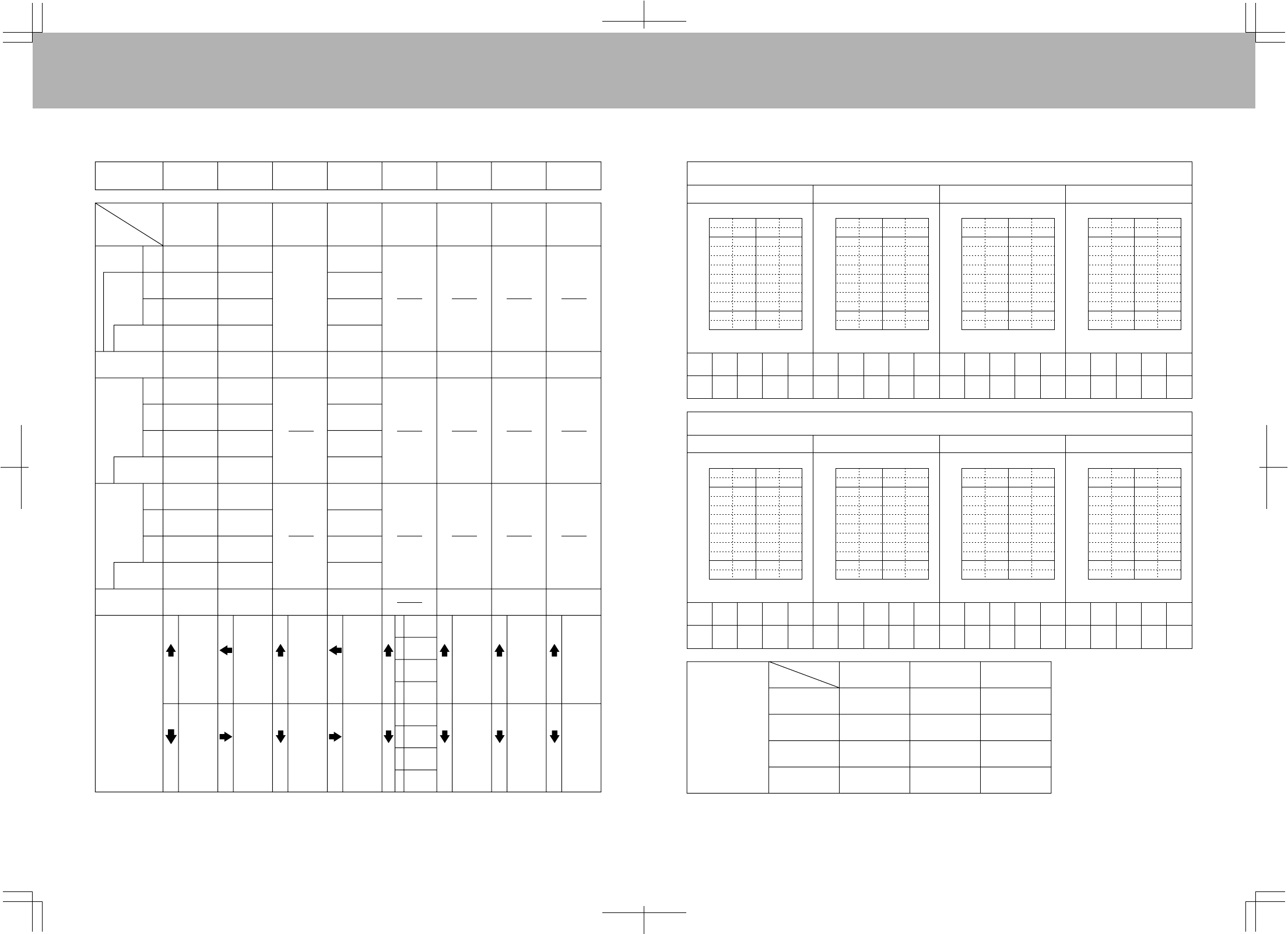
RDS8000/TYPE:HELI
MODEL#.............................................................MODELNAME....................................................
RDS8000/TYPE:HELI
MODEL#.............................................................MODELNAME....................................................
SWASH TYPE
TRM
DTM
ACT
REV
CNT
EPA
DN
D/R
N
1
2
3(HOLD)
%
%
%
UP
%
EXP
NORMAL
LT
%
RT
HI
LO
LT
%
%
%
RT
N
1
2
3H
N
1
2
3H
HI
LO
CP3F CP3B CP4F CP4B
N
1
2
3(HOLD)
%
%
%
%
N
1
2
3(HOLD)
%
%
%
%
%
%
%
%
%
%
%
%
%
%
%
%
%
% % % % % %
% % % % % %
%
%
%
%
%
%
%
%
% % % % % %
%
%
%
%
%
%
%
%
%
%
%
NOR / REV NOR / REV NOR / REV NOR / REV NOR / REV NOR / REV NOR / REV NOR / REV
CH (1)EL (2)AI (3)TH (4)RU (5)G (6)P(7)7(8)8
FLIGHT MODE N
PL P1
% % % % %
P2 P3 PH
125
(%)
100
75
50
VALUE
VALUE
VALUE
VALUE
VALUE
VALUE
VALUE
VALUE
25
0
−25
POINT
PL P1 P2 P3 PH
FLIGHT MODE 1
TH-CV
PL P1
% % % % %
P2 P3 PH
125
(%)
100
75
50
25
0
−25
POINT
PL P1 P2 P3 PH
FLIGHT MODE 2
PL P1
% % % % %
P2 P3 PH
125
(%)
100
75
50
25
0
−25
POINT
PL P1 P2 P3 PH
FLIGHT MODE 3 (HOLD)
PL P1
% % % % %
P2 P3 PH
125
(%)
100
75
50
25
0
−25
POINT
PL P1 P2 P3 PH
FLIGHT MODE N
PL P1
% % % % %
P2 P3 PH
125
(%)
100
75
50
25
0
−25
POINT
PL P1 P2 P3 PH
FLIGHT MODE 1
PI-CV
PL P1
% % % % %
P2 P3 PH
125
(%)
100
75
50
25
0
−25
POINT
PL P1 P2 P3 PH
FLIGHT MODE 2
PL P1
% % % % %
P2 P3 PH
125
(%)
100
75
50
25
0
−25
POINT
PL P1 P2 P3 PH
FLIGHT MODE 3 (HOLD)
PL P1
% % % % %
P2 P3 PH
125
(%)
100
75
50
25
0
−25
POINT
PL P1 P2 P3 PH
RV PL PM PH
N
1
2
3(HOLD)
% % %
% % %
% % %
% % %
FUNCTION
8382
RDS8000/TYPE:HELI
MODEL#.............................................................MODELNAME....................................................
VALUE
T・CUT
1
MAS
R/L
150
(%)
100
50
0
VALUE
0
−50
−100
−150
NEUTRAL
MASTER STICK TRAVEL
L/H
SLV
VALUE % %
2
C-MIX
%
TRM
ON/OFF
TH・C
ON/OFF
C・M1
ON/OFF
SW・R
ON/OFF
DTM
ON/OFF
OPT
ALL ON
:
NOR /
REV
INH /
ACT
ON /
OFF
STW
STEP
SW・R
DTM
BASIC
REV
ON/OFF
PI・C
ON/OFF
C・M2
ON/OFF
CPY
ON/OFF ON/OFF
D/R
ON/OFF
T・CUT
ON/OFF
STW
ON/OFF
RST
ON/OFF
SWH
EXP
ON/OFF
RVL
ON/OFF
INT
ON/OFF
CNT
ON/OFF
STEP
ON/OFF
CLK
ON/OFF
EPA
ON/OFF
NAM
ON/OFF
TYP
ON/OFF
MAS
R/L
150
(%)
100
50
−50
−100
−150
NEUTRAL
MASTER STICK TRAVEL
L/H
SLV
VALUE % %
EL AI TH RU GY PI 7 8
EL AI TH RU GY PI 7 8
EL AI TH RU GY PI 7 8
EL AI TH RU GY PI 7 8