Sanyo Electric Co CPE-310-200 W-CDMA subscriber terminal User Manual odsp3
Sanyo Electric Co Ltd W-CDMA subscriber terminal odsp3
Contents
- 1. Quick reference guide
- 2. User manual part 1
- 3. User manual part 2
User manual part 2

51
Tr o u bleshooting
If multiple TCP/IP connections are listed, select the one that
contains "Ethernet", "NIC", or "10/100 MB" in its name, go to
step 4.
If TCP/IP is not listed, install it:
iClick Add.
The Select Network Component Type window opens.
ii Select Protocol from the list.
iii Click Add.
The Select Network Protocol window opens.
iv Select Microsoft from the Manufacturers list.
vSelect TCP/IP from the Network Protocols list.
vi Click OK.
vii Insert the Windows 98 or ME CD or reboot the computer if
prompted to do so.
viii If the PC reboots, repeat steps 1 to 3.
4Check TCP/IP properties:
iClick Properties with the correct TCP/IP connection selected.
The TCP/IP Properties window opens to the IP Address tab.
ii Make sure the Obtain an IP address automatically radio
button is enabled.
iii Click the DNS Configuration tab.
iv Make sure the Disable DNS radio button is enabled.
vClick OK on the TCP/IP Properties window.
vi Click OK on the Network window.
vii Restart the computer if prompted to do so.
5Check your Internet connection by launching a Web browser on
the computer connected to the indoor unit.
If your browser automatically opens to your service provider’s
Web site, full service has already been activated and you can
begin using your SOMAport for Internet service.
If your browser does not automatically open to your service
provider’s Web site, go to step 6.
6Enter a valid Internet address (such as www.google.com) in the
Address field and press Enter.
If the Web page opens, full service has already been activated
and you can begin using your SOMAport for Internet service.

52
Tr o u bleshooting
If your service provider’s Web page opens, activate full service
by following the sign-up procedure that is provided on the Web
site.
If your computer attempts an Internet connection using an old
dial-up connection, see "The Computer Uses an Old Dial-Up
Connection" on page 46.
If you do not establish an Internet connection, see "Finding
Causes of Computer Problems" on page 36.
To change network settings in Windows 2000
1Right-click the My Network Places icon and choose Properties
from the pull-down menu.
The Network and Dial-up Connections window opens.
2Select the Local Area Connection icon.
If there are multiple local area connections, read the device
name beside each icon and double-click the one that is
associated with the Ethernet card.
If there is no icon, the Ethernet card has not been properly
installed. Install the Ethernet card by following the
manufacturer’s instructions, then return to this procedure.
The Local Area Connection Status window opens.
3Click Properties.
The Local Area Connection Properties window opens.
4Select Internet Protocol (TCP/IP).
If Internet Protocol (TCP/IP) is not listed, install it as follows:
iClick Install.
The Select Network Component Type window opens.
ii Select Protocol from the list.
iii Click Add.
The Select Network Protocol window opens.
iv Select Internet Protocol (TCP/IP).
vClick OK.
vi Insert the Windows 2000 CD or reboot the computer if
prompted to do so.
vii If the PC reboots, repeat steps 1 to 4.

53
Tr o u bleshooting
5Check TCP/IP properties:
iClick Properties.
ii The Internet Protocol (TCP/IP) Properties window opens to the
General tab.
iii Make sure the Obtain an IP address automatically radio
button is enabled.
iv Make sure the Obtain DNS server address automatically
radio button is enabled.
vClick OK on the Internet Protocol (TCP/IP) Properties window.
vi Click OK on the Local Area Connection Properties window.
vii Click Close on the Local Area Connection Status window.
viii Restart the computer if prompted to do so.
6Check your Internet connection by launching a Web browser on
the computer connected to the indoor unit.
If your browser automatically opens to your service provider’s
Web site, full service has already been activated and you can
begin using your SOMAport for Internet service.
If your browser does not automatically open to your service
provider’s Web site, go to step 7.
7Enter a valid Internet address (such as www.google.com) in the
Address field.
If the Web page opens, full service has already been activated
and you can begin using your SOMAport for Internet service.
If your service provider’s Web page opens, activate full service
by following the sign-up procedure that is provided on the Web
site.
If your computer attempts to connect to the Internet using an
old dial-up connection, see "The Computer Uses an Old Dial-
Up Connection" on page 46.
If you do not get an Internet connection, see "Finding Causes
of Computer Problems" on page 36.

54
Tr o u bleshooting
To change network settings in Windows XP
1Choose Start → Settings → Network Connections.
The Network Connections window opens.
2Select the Local Area Connection icon.
If there are one or more Local Area Connection icons,
double-click the Local Area Connection icon that is associated
with the Ethernet card.
If there is no icon, the Ethernet card has not been properly
installed. Install the Ethernet card by following the
manufacturer’s instructions, then return to this procedure.
The Local Area Connection Status window opens.
3Click Properties.
The Local Area Connection Properties window opens.
4Select Internet Protocol (TCP/IP).
If Internet Protocol (TCP/IP) is not listed, install it as follows:
iClick Install.
The Select Network Component Type window opens.
ii Select Protocol from the list.
iii Click Add.
The Select Network Protocol window opens.
iv Select Internet Protocol (TCP/IP).
vClick OK.
vi Insert the Windows XP CD or reboot the computer if prompted
to do so.
vii Once TCP/IP has been installed, repeat steps 1 to 4.
5Check TCP/IP properties:
iClick Properties.
The Internet Protocol (TCP/IP) Properties window opens to the
General tab.
ii Make sure the Obtain an IP address automatically radio
button is enabled.
iii Make sure the Obtain DNS server address automatically
radio button is enabled.
iv Click OK on the Internet Protocol (TCP/IP) Properties window.

55
Tr o u bleshooting
vClick OK on the Local Area Connection Properties window.
vi Click Close on the Local Area Connection Status window.
vii Restart the computer if prompted to do so.
6Check your Internet connection by launching a Web browser on
the computer connected to the indoor unit.
If your browser automatically opens to your service provider’s
Web site, full service has been activated.
If your browser does not automatically open to your service
provider’s Web site, go to step 6.
7Enter a valid Internet address (such as www.google.com) in the
Address field and press Enter.
If the Web page opens, full service has already been activated
and you can begin using your SOMAport for Internet service.
If your service provider’s Web page opens, activate full service
by following the sign-up procedure that is provided on the Web
site.
If your computer attempts an Internet connection using an old
dial-up connection, see "The Computer Uses an Old Dial-Up
Connection" on page 46.
If you do not get an Internet connection, see "Finding Causes
of Computer Problems" on page 36.
To change network settings in Mac OS 8 and 9
NOTE: Your computer must have an Ethernet card and Open
Transport networking software to connect to the Internet.
1Click the Apple icon and choose Control Panels > TCP/IP.
The TCP/IP window opens.
2Select Ethernet from the Connect via pop-up menu.
3Select Using DHCP Server from the Configure pop-up menu.
4Close the TCP/IP control panel.
If you made any changes, save them when prompted.
5Restart your computer.
6Check your Internet connection by launching a Web browser on
the computer connected to the indoor unit.

56
Tr o u bleshooting
If your browser automatically opens to your service provider’s
Web site, full service has already been activated.
If your browser does not automatically open to your service
provider’s Web site, go to step 7.
7Enter a valid Internet address (such as www. google.com) in the
Address field.
If the Web page opens, full service has already been activated
and you can begin using your SOMAport for Internet service.
If your service provider’s Web page opens, activate full service
by following the sign-up procedure that is provided on the Web
site.
If you do not establish an Internet connection, see "Finding
Causes of Computer Problems" on page 36.
To change network settings in Mac OS X
1Click the Apple icon and choose System Preferences.
2Choose View → Network.
3Choose Built-in Ethernet from the Show pop-up menu.
4Click the TCP/IP tab, if necessary.
5Choose Using DHCP from the Configure pop-up menu.
6Click Apply Now.
7Restart your computer.
8Check your Internet connection by launching a Web browser on
the computer connected to the indoor unit.
If your browser automatically opens to your service provider’s
Web site, full service has already been activated.
If your browser does not automatically open to your service
provider’s Web site, go to step 6.
9Enter a valid Internet address (such as www.google.com) in the
Address field and press Enter.
If the Web page opens, full service has already been activated
and you can begin using your SOMAport for Internet service.

57
Tr o u bleshooting
If your service provider’s Web page opens, activate full service
by following the sign-up procedure that is provided on the Web
site.
If you do not establish an Internet connection, see "Finding
Causes of Computer Problems" on page 36.

58
Tr o u bleshooting
IP ADDRESS NEEDS
TO BE RENEWED
If you cannot connect to the Internet even after you have checked all cabling and
network settings and have rebooted the computer, follow the appropriate procedure
in this section to manually obtain a new IP address.
To obtain a new IP address (Windows 95 only)
1Choose Start → Run.
2Enter winipcfg in the Open field and click OK.
The IP Configuration window opens.
3Select the network interface that has a default gateway of
192.168.1.1 from the pull-down list.
4Click Release All.
5Force your computer to obtain a new IP address by clicking
Renew All.
Wait until the fields in the IP Configuration window have values in
them or an error message appears. If you close this program
before it has completed its task, you will have to reboot your
computer before you can use your Internet service.
6Close the IP Configuration window.
To obtain a new IP address (all other versions of Windows)
1Open a command window using one of the following methods:
In Windows 2000 or XP, choose
Start → Programs → Accessories → Command Prompt.
In Windows 98 or ME, choose Start → Programs → MS-
DOS Prompt.
The command window opens.

59
Tr o u bleshooting
2Force your computer to obtain a new IP address by typing the
appropriate command from the following table:
The Windows IP configuration is displayed.
3Look for the output section related to the network interface for the
SOMAport.
Example:
Ethernet adapter:
IP address............. : 65.94.64.233
Subnet Mask............ : 255.255.255.0
Default Gateway........ : 192.168.1.1
4Close the MS-DOS Prompt or Command Prompt window.
Operating System Command
Windows 98 or ME ipconfig /renew_all ↵
Windows 2000 or XP ipconfig /renew ↵

60
Tr o u bleshooting

61
SPECIFICATIONS
Release Outdoor SOMAport R3.0
Internal antenna Type: internal passive-steered array antenna
Internal antenna gain: 4.5 dBi
Reciever noise figure: 6 dB
Transmitted EIRP: 31.5 dBm
RF output power: 27 dBm
Device ports and
Interfaces Telephone
Telephone terminal interface (RJ-11 jacks) (2)
Data
Data terminal interface (RJ-45 Ethernet 10Base-T)
AC Adapter
AC Adapter (Coaxial DC Power Jack, 30AV/2A)
Between Outdoor Unit and Indoor Unit
CAT-5 Ethernet w/Power feed and two telephone lines
Lights
(Indoor Unit) Power, Network
Power
Requirements Power Supply
Type: U.S./International 100/240V AC-DC external power supply
Cable: Power cord with non-wall-mounted AC-to-DC transformer
Environmental
Specifications
(Outdoor Unit)
Temperature
Operating: 5°C to 40°C (+46°F to +104°F) (w/o Heater)
Humidity
Operating: 0% to 85%, noncondensing
Altitude
Operating: 2438 m (8000 feet)
Water Proof
IP25
Packaging Dimensions
Outdoor Unit
Height: 18.5 cm (7.3 inches)
Width: 21 cm (8.3 inches)
Depth: 21 cm (8.3 inches)
Weight: 3 kg (6.7 pounds)
Volume: 8000 cc
Indoor Unit
4.6 cm (1.8 inches)
10.4 cm (4.1 inches)
8.4 cm (3.3 inches)
0.3 kg (0.7 pounds)
400 cc
Regulatory
Certifications IEC 61000-4-5 class 3
CE
CB Scheme (IEC60950-1)
FCC Part 15B, Part 24 (PCS Only)

62

OUTDOOR SOMAPORT
INSTALLATION GUIDE
Part 006217 revision 01
WARNING: The installation procedures described in this
chapter are intended only for qualified technicians. Non-
qualified personnel should not perform this installation.


65
Introduction ....................................................................... 67
Overview ......................................................................................... 68
System Components ........................................................................ 69
The Outdoor Unit Assembly ........................................................... 70
Do You Have Everything? ............................................................... 71
Antenna ........................................................................................... 74
Safety Precautions ............................................................................ 75
Installing the Outdoor Unit ............................................... 77
Installation Overview ....................................................................... 78
Installation Guidelines and Requirements ........................................ 79
Estimating Cable Requirements ....................................................... 81
Assembling Mounting Bracket and Pipe .......................................... 82
Installing the Outdoor Unit on Solid wood or Lap Siding ............... 87
Installing the Outdoor Unit on Brick or Poured Concrete ............... 91
Installing the Outdoor Unit on a Cinder-block or Hollow wall ....... 94
Installing the Outdoor Unit on a Roof ............................................. 96
Attaching the Outdoor Unit to the Mounting Assembly .................. 99
Installing the Indoor Unit ................................................ 101
An overview of the Installation ....................................................... 102
Choosing the Best Location for the Indoor Unit ............................ 103
Routing Cable to the Indoor Unit ................................................. 104
Connecting the Power Supply and Powering on the Indoor Unit .. 107
Connecting Computers and Telephones to the Indoor Unit .......... 108
CONTENTS

66

67
This chapter provides an overview of the Outdoor SOMAport.
Contents
Overview ............................................................................................................. 68
System Components ........................................................................................... 69
The Outdoor Unit Assembly ................................................................................ 70
Do You Have Everything? ................................................................................... 71
Antenna ............................................................................................................... 74
Safety Precautions .............................................................................................. 75
INTRODUCTION

68
Introduction
OVERVIEW
The Outdoor SOMAport™ subscriber terminal provides high-speed Internet access
and telephone service. The SOMAport works like a cell phone, in that it
communicates with your service provider’s network over the air and does not require
a special wire connection.
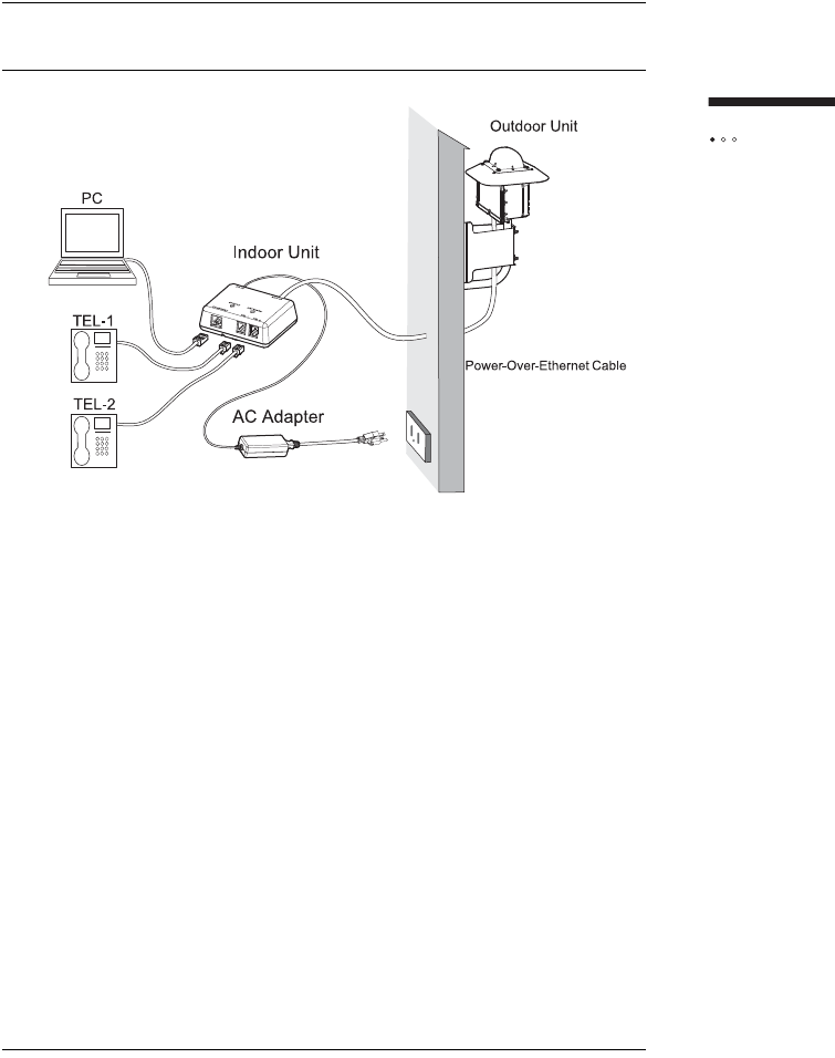
The SOMAport consists of two parts: an outdoor unit and an indoor unit. After
installing the SOMAport, simply plug-in the indoor unit and connect it to your
computer using the provided Ethernet cable. The SOMAport will automatically
connect to your service provider and you can setup your account using a Web
browser.
If you are using your SOMAport to provide telephone service, you can connect
ordinary telephones to it.
Internet service
The SOMAport provides a high-speed, "always on" internet connection, which
means you can be connected to the Internet and still use your telephone. The
SOMAport is designed to be left on – it should not be turned off when not in use.
Telephone service
The telephone service provided by the SOMAport is independent and separate from
your phone service. Wireless services may differ from your traditional wired services.
Consult with your wireless service provider for details.
69
Introduction
SYSTEM COMPONENTS
Outdoor Unit: The outdoor unit is a ruggedized box, typically pipe-mounted, that
contains a radio modem and an internal antenna. It uses a single cable (CAT5) that
transmits data, telephone, and power to and from the indoor unit.
Indoor Unit: The indoor unit is placed inside subscriber’s residence and connects to
the subscriber’s computer and telephones. The indoor unit also functions as an AC
adapter for the outdoor unit.
70
Introduction
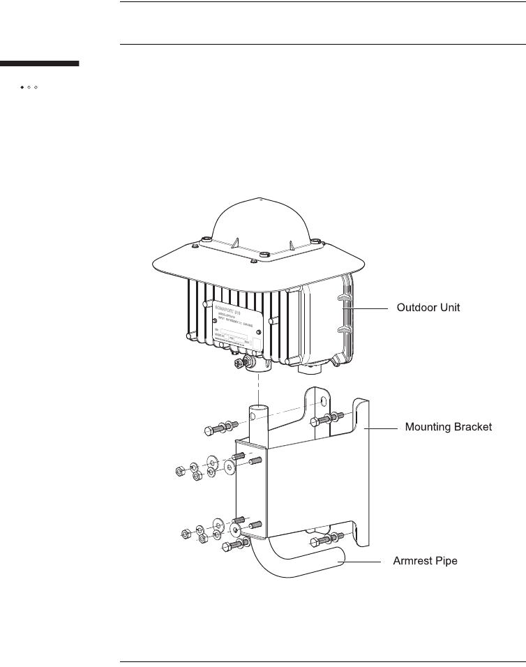
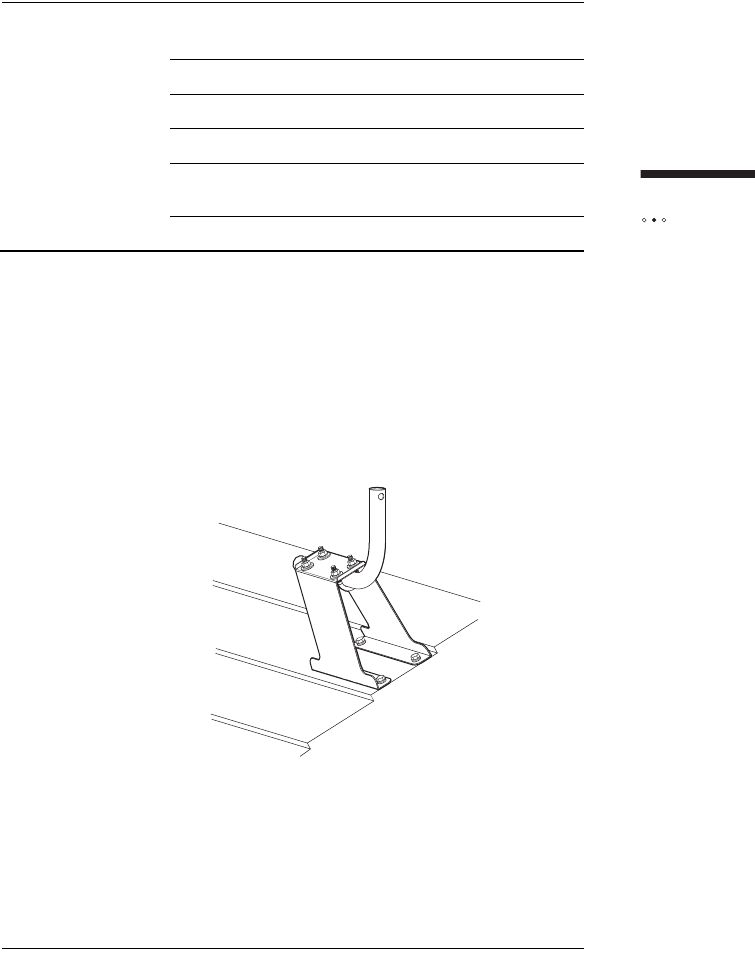
THE OUTDOOR UNIT ASSEMBLY
The following illustration shows the three main pieces that are shipped and that
must be assembled as part of the installation.
Outdoor unit
Mounting bracket
Armrest pipe

71
Introduction
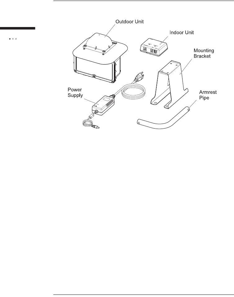
DO YOU HAVE EVERYTHING?
Before you begin, make sure you have everything you will need during the
installation.
The basic Outdoor SOMAport kit
Verify that the kit contains the following parts:
Outdoor unit
Armrest pipe
Mounting bracket
Power supply
Indoor unit
Wood screws 3.1 x 32 (4)
Hexagon P-Less anchors 6 x 45 (4)
Flat washers, nominal diameter 6 (8)
Spring washers, nominal diameter 6 (8)
Hexagon nuts M6 (4)
U-bolts M6 (2)
User Guide
Installation Guide
72
Introduction
The installation kit
The installation kit is an optional set of mounting hardware provided for subscribers
who want to install the outdoor unit themselves. The kit contains the hardware you
need to install the outdoor unit on a variety of surfaces (wall or roof). If you have
this kit, verify that it contains the following parts
CAT5 cable assembly kit
Cable: AWG26 4P EM-TPMC-C5 (SLA) (Oki Electric Cable)
Outdoor unit side RJ-45 connector:
CN078P-080-001 (YAMAICHI)
CN078A-2023 (YAMAICHI)
CN078A-2010 (YAMAICHI)
CN078A-2003 (YAMAICHI)
Indoor unit side RJ-45 connector:
CN078P-080-0001 (YAMAICHI)
CN078A-2001 (YAMAICHI)
Oxide-inhibiting compound
10 cable clips

73
Introduction
Materials and tools
In addition, you need the following materials and tools, which are not supplied with
the basic Outdoor SOMAport or installation kits:
8, 10, 13 mm socket or open-end or box-end wrench or small adjustable
wrench
Phillips-head screw driver No.2
Pencil or chalk
Carpenter’s level
Silicone sealant
Double-expansion anchors
Electric drill with one of the following drill bits:
Diameter (Ø) 2.0, Ø4.5 Woodworking drill (if installing on wood or a roof)
Ø5.3 concrete drill (if installing on concrete or brick)
Ø10-20 mm woodworking or concrete drill (if you make hole for passing the
cable)
Sticking-by-pressure tool (for RJ-45)
Covering slit tool (for RJ-45)
Guide insertion tool (for RJ-45)
Network cable tester (for RJ-45)

74
Introduction
ANTENNA
The outdoor unit communicates with a cellular tower operated by your wireless
service provider. The outdoor unit contains an antenna that automatically steers
itself toward the best signal when you plug in the SOMAport. It also periodically
checks to see if the current antenna direction is optimal and adjusts automatically if
required.
!WARNING: While this device is in operation, a separation
distance of at least 20 centimeters (8 inches) must be
maintained between the radiating antenna and any person
exposed to the transmitter in order to meet the FCC RF
exposure guidelines. No change to the antenna or device is
permitted. Doing so may result in the installed system
exceeding RF exposure requirements. This device must
not be co-located or operating in conjunction with any other
antenna or radio transmitter. Installers and end users must
follow the installation instructions provided in this guide.

75
Introduction
SAFETY PRECAUTIONS
In addition to the safety instructions on page 11, follow these guidelines when
installing the Outdoor SOMAport:
Carefully survey the job site before beginning the installation to locate secure
handholds, dangerous conditions (such as power lines and weak roofs), and
the safest and most convenient placements for ladders.
Do not climb on a wet or icy roof.
Do not attempt high installations on windy days.
Use only the sturdiest commercial-grade ladders – those with wide, slip
preventive rungs and bases.
Do not position ladders at an angle steeper than 70°. Steeper angles can cause
a ladder to slip sideways.
Dig the base of the ladder into the ground if possible.
Do not place ladders on slate that is wet or hot.
Wear rubber-soled, low-heeled shoes or boots.
Wear a pair of durable but flexible protective gloves whenever they won’t
interfere with the installation process.
Take care not to bump or bang the outdoor unit against anything.
Perform as many installation steps as possible on the ground.
!WARNING: The outdoor unit must not be used indoors. It
must be mounted on a permanent outdoor structure.
!WARNING: Do not connect any third-party devices to the
outdoor unit, CAT5 cable, or indoor unit. Damage may
occur.

76
Introduction

77
This chapter describes how to install the outdoor unit using a variety of mounting
options. Be sure to read the important safety information in the front pages of this
manual before beginning an installation.
Contents
Installation Overview ........................................................................................... 78
Installation Guidelines and Requirements ........................................................... 79
Estimating Cable Requirements .......................................................................... 81
Assembling Mounting Bracket and Pipe .............................................................. 82
Installing the Outdoor Unit on Solid wood or Lap Siding ..................................... 87
Installing the Outdoor Unit on Brick or Poured Concrete .................................... 91
Installing the Outdoor Unit on a Cinder-block or Hollow wall .............................. 94
Installing the Outdoor Unit on a Roof .................................................................. 96
Attaching the Outdoor Unit to the Mounting Assembly ........................................ 99
INSTALLING THE
OUTDOOR UNIT

78
Installing
the outdoor unit
INSTALLATION OVERVIEW
Before you begin the installation, make sure you have read the important notice on
page 13 and the safety instructions on page 11.
Installation tasks
To install the outdoor unit, you must carry out the following tasks in the specified
order.
Step Page
1 Choose a site. 78
2 Estimate cabling requirements. 81
3 Assemble mounting bracket and armrest pipe. 82
4 Install the outdoor unit on one of the following surfaces.
External wall with a wood or lap siding surface
External wall with a brick or poured concrete surface
External hollow or cinder block wall
Rooftop
87
91
94
96
5 Attach the outdoor unit to the armrest pipe. 99

79
Installing
the outdoor unit
INSTALLATION GUIDELINES
AND REQUIREMENTS
Guidelines
Follow these guidelines to optimize the received radio signal. The outdoor unit
works best when:
Installed at the highest possible point
Placed as far away as possible from obstructions, such as trees or tall buildings
Requirements
The installation must meet the following requirements:
The outdoor unit must not be used indoors. The outdoor unit must be
installed on an outdoor permanent structure such as a roof or an external
wall.
All four sides of the outdoor unit must be unobstructed. Leave a clear zone of
at least 6 cm (2.4 inches) around the outdoor unit.
The installed height of the outdoor unit must be at least 3 m (10 feet) to
ensure that it is safely out of reach. For example, if the outdoor unit is
installed on the side of a building, it should be at least 3 m (10 feet) off the
ground. If installed on a rooftop that is accessible, the outdoor unit must be
at least 3 m (10 feet) above the rooftop.
!WARNING: While this device is in operation, a separation
distance of at least 25 cm must be maintained between the
radiating antenna inside the outdoor unit and the bodies of
all persons exposed to the transmitter in order to meet the
FCC RF exposure guidelines. Making changes to the
antenna or the device is not permitted. Doing so may result
in the installed system exceeding RF exposure
requirements. This device must not be co-located or
operated in conjunction with any other antenna or radio
transmitter. Installers and end users must follow the
installation instructions provided in this guide.

80
Installing
the outdoor unit
!WARNING: Do not touch (or allow the outdoor unit or any
cabling or ladder to touch) power lines, electric lights, and
power circuits, as contact with them may be fatal. Locate
the outdoor unit more than 6 m (20 feet) from overhead
power lines. If any part of the outdoor unit comes into
contact with a power line, call your local power company.
Do not try to remove it yourself.

81
Installing
the outdoor unit
ESTIMATING CABLE REQUIREMENTS
After you have selected the location for the installation, decide where you want the
cable to enter the building and estimate how much cable you will need.
Cable restrictions
You must use CAT5 cable to connect the outdoor unit to the indoor unit. The total
length of the CAT5 cable must not exceed 50 m (167 feet). You cannot use a line
amplifier.
To estimate how much cable is required
1ldentify where the indoor unit is located.
2Estimate the amount of cable required for a CAT5 cable.
82
Installing
the outdoor unit
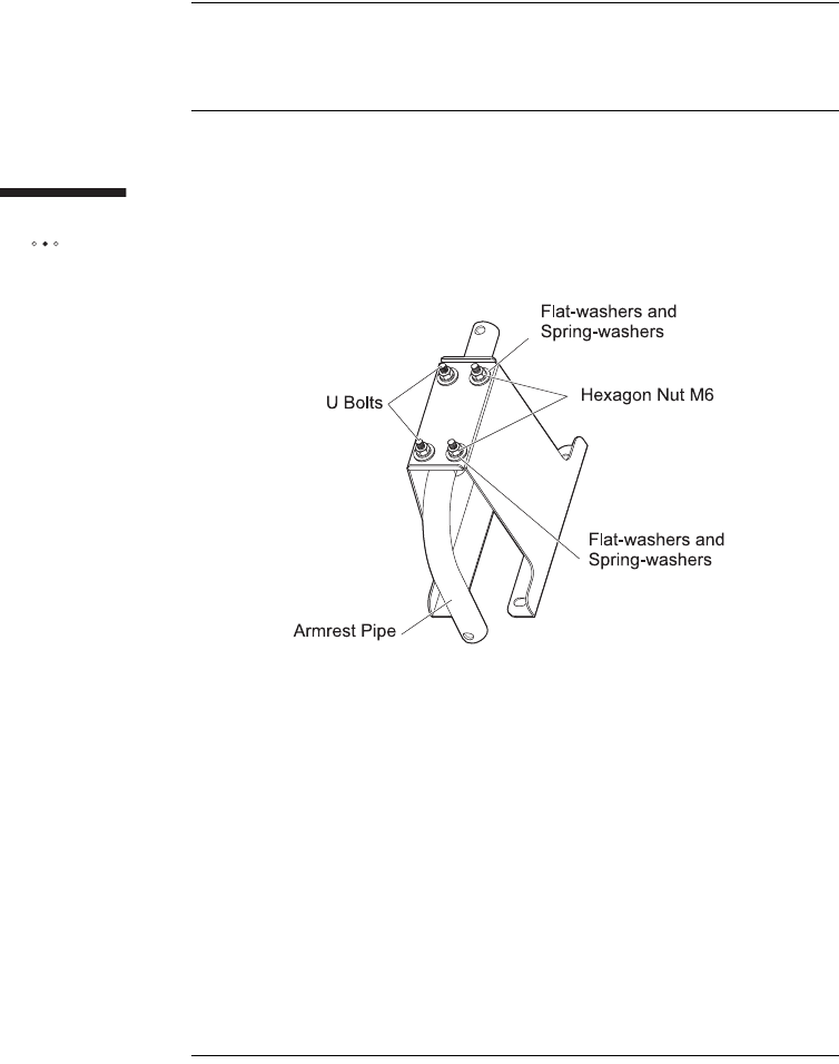
ASSEMBLING MOUNTING BRACKET
AND PIPE
This section describes how to attach mounting bracket to the outdoor unit.The
recommended procedure is to attach the bracket-and-pipe assembly to the mounting
surface (wall or roof) and then attach the outdoor unit to the armrest pipe. This
makes it easier to handle the assembly while attaching it to the mounting surface.
.

83
Installing
the outdoor unit
Tools and materials
Make sure you have the following items on hand before you begin.
Materials Mounting bracket
Armrest pipe
Flat washers, nominal diameter 6 (4)
Spring washers, nominal diameter 6 (4)
Hexagon nuts M6 (4)
U-bolt M6 (2)
Tools 8, 10 mm open-end or box-end wrench or a small
adjustable wrench
84
Installing
the outdoor unit
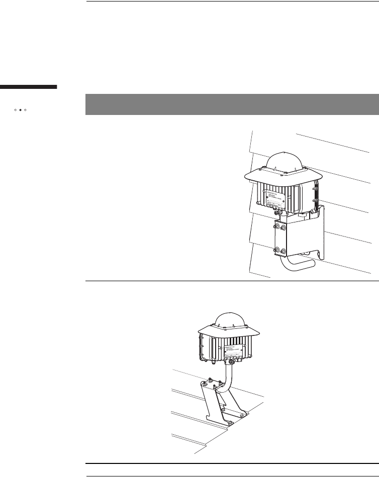
Mounting Options
The way in which you assemble mounting bracket and armrest pipe depends on the
mounting option you choose. The following table shows sample wall and rooftop
installations to illustrate how the parts must be assembled for each mounting option.
The procedure on page 85 describes how to attach the armrest pipe to mounting
bracket for the various mounting options.
Option Sample Installation
Wall
Rooftop
85
Installing
the outdoor unit
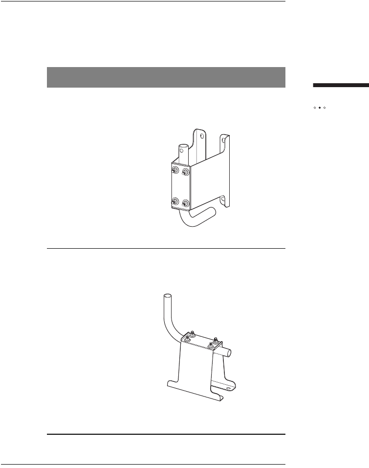
To assemble the mounting bracket and pipe
1Slide the mounting bracket over the long end of the armrest pipe
and then assemble it according to the mounting option you have
chosen:
Option Assembly
Wall Set free end of the armrest pipe toward the
installation surface.
Rooftop Set free end of the armrest pipe vertical
against the ground surface.

86
Installing
the outdoor unit
2Put two U-bolts thourgh the hole of the mouting bracket from
inside of the bracket.
3Attach flat washers, spring washers, and nuts in this order onto U-
bolts sticking out of the mounting bracket.
4Insert longer straight end of the armrest pipe into the space
between U-bolts and the mounting bracket, then tighten the nuts of
U-bolts.
NOTE: Do not fully tighten the hex nuts yet. You may need to
adjust the orientation of the pipe.
5Fully tighten the nuts to fix the armrest pipe in the direction suitable
for the installation position.
WARNING: Make sure the indoor unit is powered off
before you install the outdoor unit and connect any cables
to it.
87
Installing
the outdoor unit
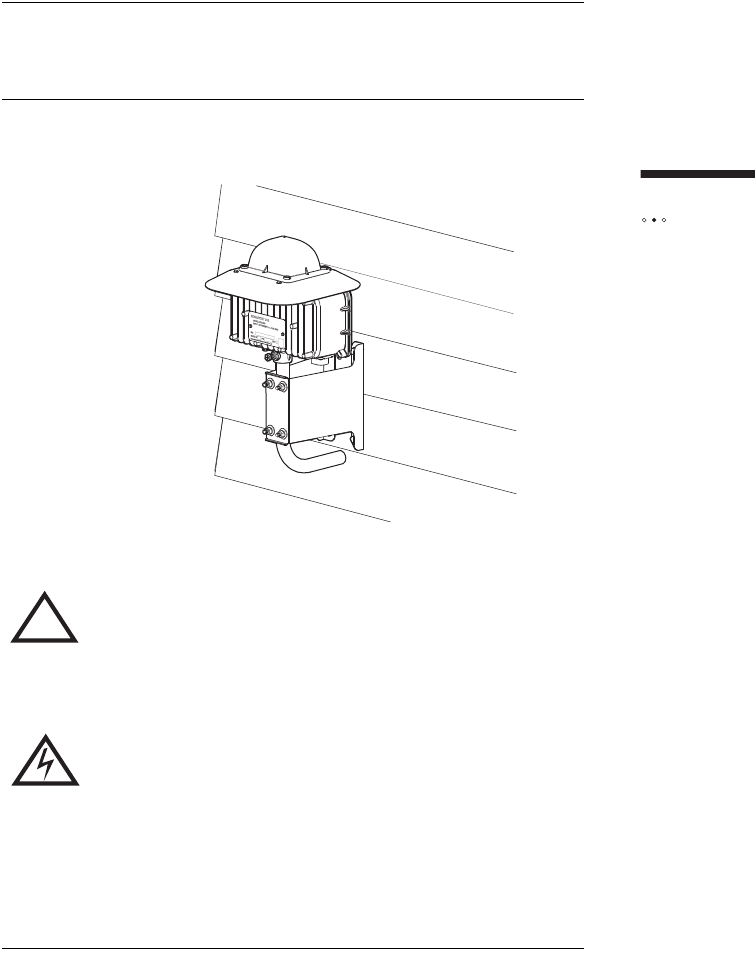
INSTALLING THE OUTDOOR UNIT
ON SOLID WOOD OR LAP SIDING
The following illustration shows an installation on an external wall with wood or lap
siding.
!WARNING: Do not mount the outdoor unit on any type of
aluminum or vinyl siding or on any type of composite
paneling, such as fiber board, particle board, or strand
board. If the surface is made of wood, make sure it is
structurally sound.
WARNING: Do not touch (or allow the outdoor unit or any
cabling or ladder to touch) power lines, electric lights, and
power circuits, as contact with them may be fatal. Locate
the outdoor unit more than 6 m (20 feet) from overhead
power lines. If any part of the outdoor unit comes into
contact with a power line, call your local power company.
Do not try to remove it yourself.

88
Installing
the outdoor unit
Tools and materials
Make sure you have the following items on hand before you begin.
Materials Hex P-Less anchors 6 x 45 (4)
Flat-washers, nominal diameter 6 (4)
Spring-washers, nominal diameter 6 (4)
Tools Woodworking Ø4.5 mm drill bit
Carpenter’s level
Screwdriver
Hammer
8, 10 mm open-end or box-end wrench or a small adjustable
wrench
Pencil or chalk

89
Installing
the outdoor unit
To install the mounting assembly on a wall made of wood
or lap siding
1Locate the center of a stud if you are mounting the outdoor unit on:
Lap siding
Wood siding that is less than 3.5 cm thick.
ATTENTION: Do not mount the outdoor unit near the edge of a
stud. Make sure you mount it on the center of a stud.
2Hold mounting bracket-and-pipe assembly in a position in which its
center line is centered on a stud or solid wood surface.
3Use a level to verify that the center line of mounting bracket is
perfectly vertical.
4Use a pencil or a piece of chalk to mark the position of the holes in
mounting bracket:
If you are installing the outdoor unit on a stud, mark the
locations of the two center holes, which are positioned over
the stud.
If you are not installing the outdoor unit on a stud, mark the
positions of the four holes that are located in the four corners
of mounting bracket. Do not mark the center holes.
5Remove mounting bracket-and-pipe assembly.
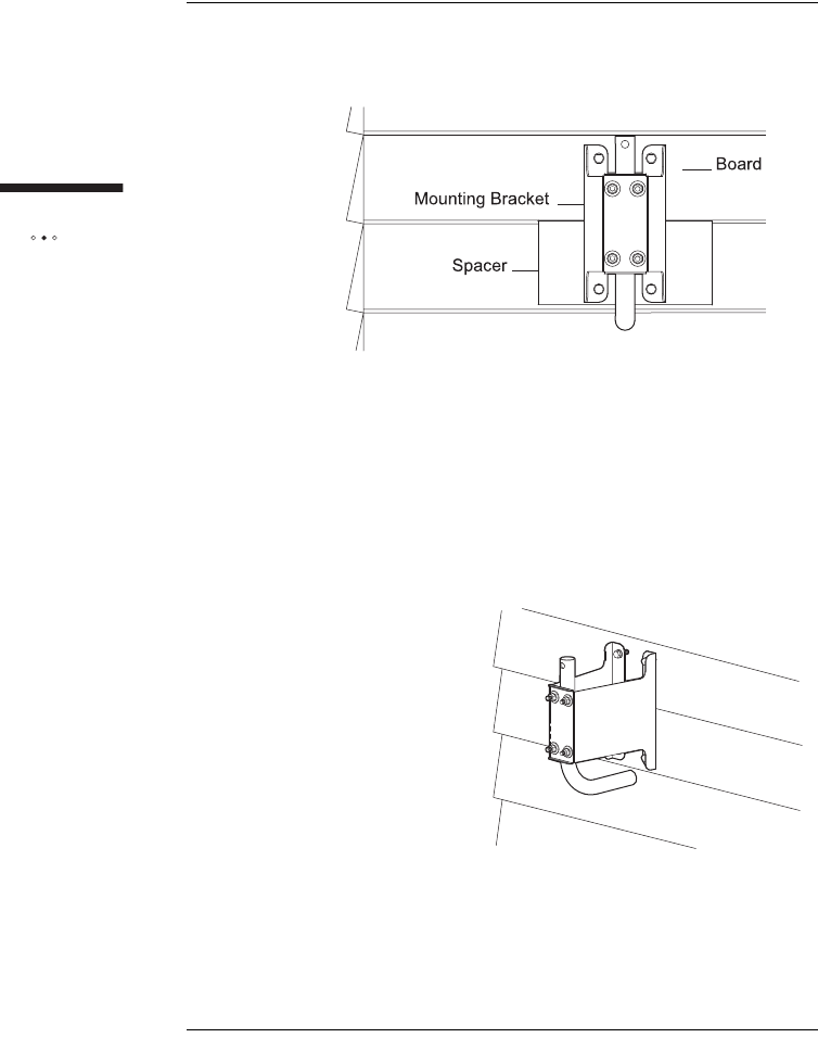
6If the mounting bracket spans two pieces of siding, use a spacer
made of solid wood or plastic.
iPosition the mounting bracket-and-pipe assembly so that most
of the mounting bracket’s base is on the top board.
90
Installing
the outdoor unit
ii Install the spacer on the bottom board to help hold the bottom
of the mounting bracket in place.
7Drill a 4.5 mm hole in each of the locations you marked.
8Hold mounting bracket-and-pipe assembly over the holes so that
the long end of the pipe points straight up.
9Insert 6 x 45 mm Hex P-Less anchor in each of the holes to attach
the mounting bracket to the wall.
10 Tighten the screws to secure mounting bracket-and-pipe assembly
to the wall.
11 Attach the outdoor unit to the mounting assembly as described in
the section "Attaching the Outdoor Unit to the Mounting Assembly"
on page 99.
91
Installing
the outdoor unit
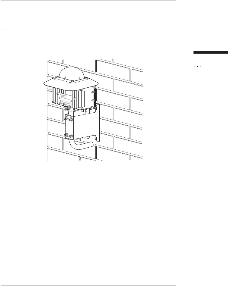
INSTALLING THE OUTDOOR UNIT
ON BRICK OR POURED CONCRETE
The following illustration shows an installation on an external wall that is made of
brick or poured concrete.
This installation option requires the use of wall anchors, which must have a strength
of at least 135 kg (300 pounds) of pull-out pressure. Equivalent double-expansion
anchors are recommended.

92
Installing
the outdoor unit
Tools and materials
Make sure you have the following items on hand before you begin.
To install the outdoor unit on brick or poured concrete
1Hold mounting bracket-and-pipe assembly in position on the
mounting surface.
NOTE: Do not drill into mortar joints. Ensure the holes are
positioned over brick.
2Use a level to verify that the center line of mounting bracket is
perfectly vertical.
3Use a pencil or a piece of chalk to mark the position of the four
holes that are located in the four corners of mounting bracket.
4Remove mounting bracket-and-pipe assembly.
5Drill a hole of sufficient diameter in each of the locations you
marked to a depth equal to or slightly greater than the length of the
expansion anchor.
6Insert a double-expansion anchor in each hole. The top end of the
anchor should be flush or slightly below the base material surface.
7Hold mounting bracket-and-pipe assembly over the holes so that
the long end of the armrest pipe points straight up.
Materials Four equivalent double-expansion anchors
Four machine screws of a size appropriate for the double-
expansion anchors
Tools Electric drill with a masonry bit of a size that is appropriate for
the double-expansion
Carpenter’s level
Screwdriver
Hammer
8, 10, 13 mm open-end or box-end wrench or a small
adjustable wrench
Pencil or chalk
93
Installing
the outdoor unit
8Insert a machine screw in each of the holes to attach the mounting
bracket to the wall.
9Tighten the screws to secure mounting bracket-and-pipe assembly
to the wall.
10 Attach the outdoor unit to the mounting assembly as described in
the section "Attaching the Outdoor Unit to the Mounting Assembly"
on page 99.

94
Installing
the outdoor unit
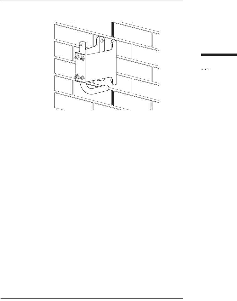
INSTALLING THE OUTDOOR UNIT
ON A CINDER-BLOCK OR HOLLOW WALL
Tools and materials
Make sure you have the following items on hand before you begin.
To install the outdoor unit on a hollow or cinder block wall
1If you are installing the outdoor unit on cinder block, you must
install the toggle bolts in the core of the block. To find the correct
location on the block:
iMeasure 19 cm (7.5 inches) from one side of the block.
ii Mark this location on the block.
2Hold the mounting bracket-and-pipe assembly in position on the
mounting surface (centered on the mark you made if installing the
outdoor unit on cinder block).
3Use a level to verify that the center line of the mounting bracket is
vertical.
4Use a pencil or a piece of chalk to mark the positions of the two
center holes of the mounting bracket.
5Remove the mounting bracket-and-pipe assembly.
6Drill a hole of sufficient diameter in each of the locations you
marked.
Materials Toggle bolts (4)
Tools Electric drill with a masonry bit of a size appropriate for the
toggle bolts
Carpenter’s level
Screwdriver
Hammer
8, 10, 13 mm open-end or box-end wrench or a small
adjustable wrench
Pencil or chalk
95
Installing
the outdoor unit
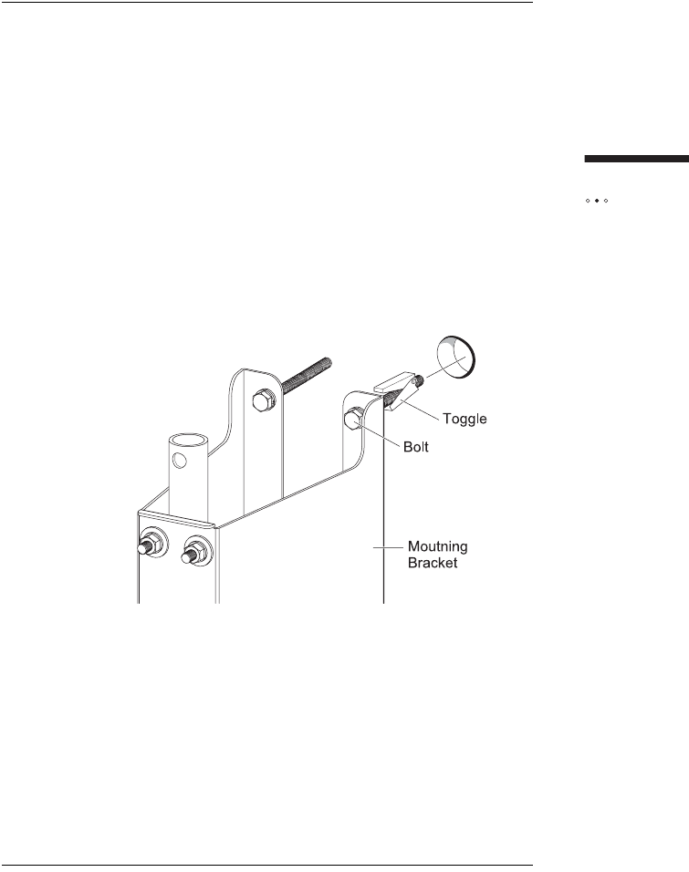
7Attach the toggle bolts to the mounting bracket:
iRemove the toggle (the wing-shaped anchor) from the bolt by
unscrewing it.
ii Screw the bolt into one of the center holes in the mounting
bracket.
iii Screw the toggle back onto the bolt.
NOTE: Do not screw the toggle on very far or it will not open
when you put it through the wall.
iv Repeat steps i to iii for the other hole.
8Attach the bracket-and-pipe assembly to the wall:
iHold the mounting bracket-and-pipe assembly over the drilled
holes so that the long end of the mounting pipe is vertical.
ii Insert the toggle bolts into the drilled holes.
iii Tighten the toggle bolts, making sure that the long end of the
mounting pipe is vertical.
9Attach the outdoor unit to the mounting assembly as described in
the section "Attaching the Outdoor Unit to the Mounting Assembly"
on page 99.
96
Installing
the outdoor unit
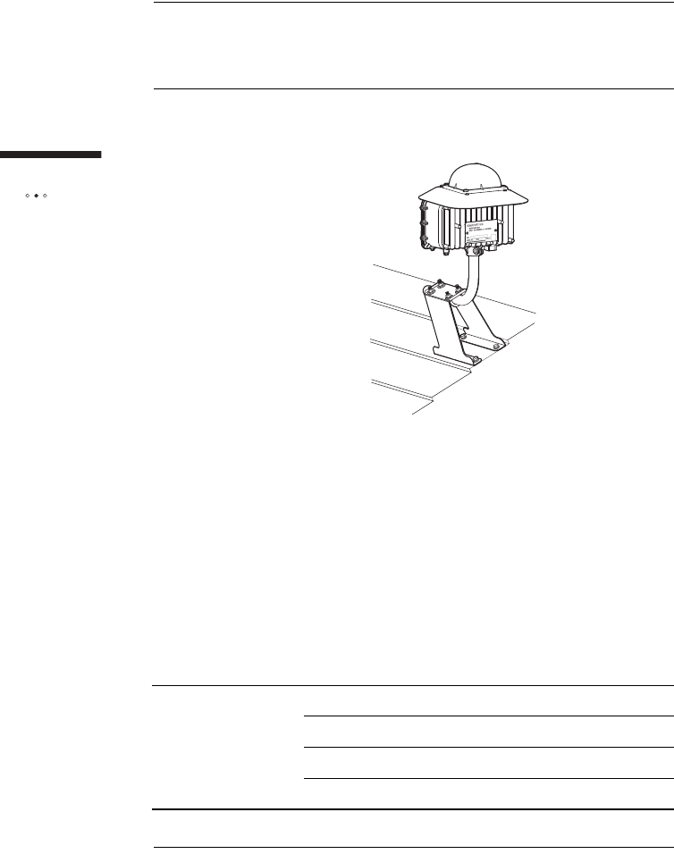
INSTALLING THE OUTDOOR UNIT
ON A ROOF
The following illustration shows a rooftop installation.
When installing the outdoor unit on a roof, install it in the highest possible location
to maximize the signal you receive.
ATTENTION: Under some conditions, walking on the roof can
cause damage, and improperly sealed mounting holes can
cause leaks. Use caution when installing the outdoor unit on the
roof.
Tools and materials
Make sure you have the following items on hand before you begin.
Materials Hex P-Less anchors 6 x 45 (4)
Flat-washers, nominal diameter 4
Spring-washers, nominal diameter 4
Roofing sealant
97
Installing
the outdoor unit
To install the mounting assembly on a roof
1Locate a rafter.
NOTE: At least two of the holes in the bracket must be
positioned over the rafter.
2Hold the long end of the bracket base across a rafter so that it is
perpendicular to, rather than parallel to, the center line of the
rafter.
3Use a carpenter’s level to make sure the center line of the bracket
is perfectly horizontal.
4Use a pencil or a piece of chalk to mark the positions of the four
holes that are located in the four corners of mounting bracket.
Tools Woodworking Ø4.5 mm drill bit
Carpenter’s level
Screwdriver
Hammer
8, 10, 13 mm open-end or box-end wrench or a small
adjustable wrench
Pencil or chalk

98
Installing
the outdoor unit
5Remove mounting bracket-and-pipe assembly.
6Drill a 4.5 mm hole in each of the locations you marked.
7Fill the holes you drilled with silicone sealant.
8Hold mounting bracket-and-pipe assembly over the holes.
9Insert a 6 x 45 mm lag Hex P-Less anchor in each of the holes to
attach the mounting bracket to the roof.
10 Tighten the screws to secure mounting bracket-and -pipe
assembly in place.
11 Use a level to see if a short end of the armrest pipe is pointing
straight up, if it is not perfectly vertical:
iUse a wrench to loosen the two U-bolts that secure mounting
bracket to the pipe.
ii Grasp the armrest pipe and rotate it until the short end of the
pipe is pointing up and is perfectly vertical.
iii Tighten the two U-bolts to hold the armrest pipe securely in a
vertical position.
12 Seal mounting bracket with roof sealant.
13 Attach the outdoor unit to the mounting assembly as described in
the section "Attaching the Outdoor Unit to the Mounting Assembly"
on page 99.
99
Installing
the outdoor unit
ATTACHING THE OUTDOOR UNIT
TO THE MOUNTING ASSEMBLY
Once mounting bracket-and-pipe assembly is securely attached to the mounting
surface and the armrest pipe is pointing straight up, you can attach the outdoor unit
to the mounting assembly.
At this point you should also attach the CAT5 cable to the bottom of the outdoor
unit in preparation for the wiring procedure that follows.
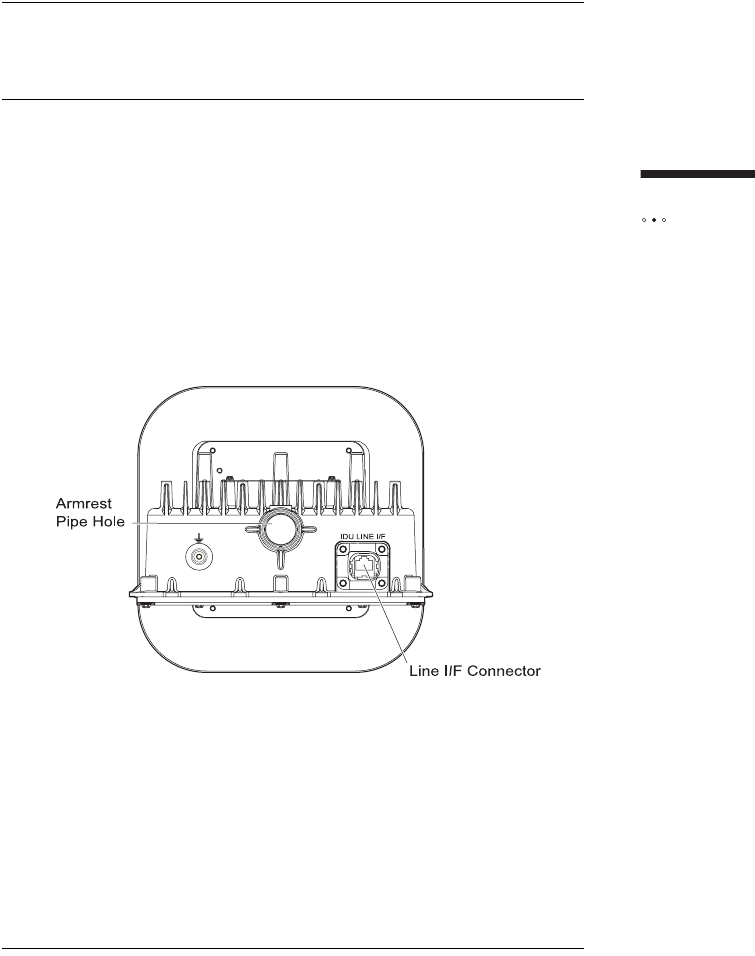
The bottom of the outdoor unit
The armrest pipe, CAT5 cable are attached to the bottom of the outdoor unit, as
described in this section.

100
Installing
the outdoor unit
Tools and materials
Make sure you have the following items on hand before you begin.
To attach the outdoor unit to the armrest pipe
1Attach the outdoor unit to the armrest pipe by sliding the hole on its
base over the armrest pipe.
2Secure the outdoor unit by tightening the M6 bolt at the outdoor
unit mount section.
3Secure detent of the M6 bolt with the M6 lock nut.
To attach the CAT5 cable to the outdoor unit
1Attach the waterproof RJ-45 connector (manufactured by
YAMAICHI) to one end of the CAT5 cable.
2Attach the waterproof RJ45 connector to Line I/F connector of the
outdoor unit.
NOTE: Make sure the connector is attached in the right
direction, and hooks on either side of the connector are
securely locked.
3Draw the other end of CAT5 cable inside to the installation position
of the indoor unit.
4Attach RJ-45 connector to the end of CAT5 cable to connect to the
indoor unit.
Materials Outdoor Unit
CAT5 cable and self-bonding tape
Tools Screwdriver
Sticking-by-pressure tool (for RJ-45)
Covering slit tool (for RJ-45)
Guide insertion tool (for RJ-45)
Network cable tester (for RJ-45)

101
This chapter describes how to connect computer and telephone equipment to the
indoor unit.
Contents
An overview of the Installation ........................................................................... 102
Choosing the Best Location for the Indoor Unit ................................................. 103
Routing Cable to the Indoor Unit ....................................................................... 104
Connecting the Power Supply and Powering on the Indoor Unit ...................... 107
Connecting Computers and Telephones to the Indoor Unit .............................. 108
INSTALLING THE
INDOOR UNIT

102
Installing
the indoor unit
AN OVERVIEW OF THE INSTALLATION
The following is an overview of the sequence of installation tasks required to connect
equipment to and power on the indoor unit.
Task See
1. Install the outdoor unit. "Install the Outdoor Unit" on page 77.
2. Choose a location for the
indoor unit. "Choosing the Best Location for the Indoor
Unit" on page 103.
3. Connect the power supply to
the indoor unit and plug in the
indoor unit to power it on.
"Connecting the Power Supply and
Powering on the Indoor Unit" on page 107.
4. Connect your computer to the
indoor unit. "Connecting a Computer via Ethernet" on
page 25.
5. If telephone service is available
in your area and you subscribe to
it, connect your telephone to the
indoor unit.
"Connecting Telephones to the Indoor Unit"
on page 26.
6. Connect to the Internet.
NOTE: You may have to activate
full service if your service
provider has not already done
so.
"Activating Service" on page 30.
103
Installing
t
he indoor unit
CHOOSING THE BEST LOCATION
FOR THE INDOOR UNIT
The indoor unit must be installed near a wall outlet. Choose the location feasible to
connect a PC and/or a telephone. Do not locate close to interfering appliances such
as a microwave.
104
Installing
the indoor unit
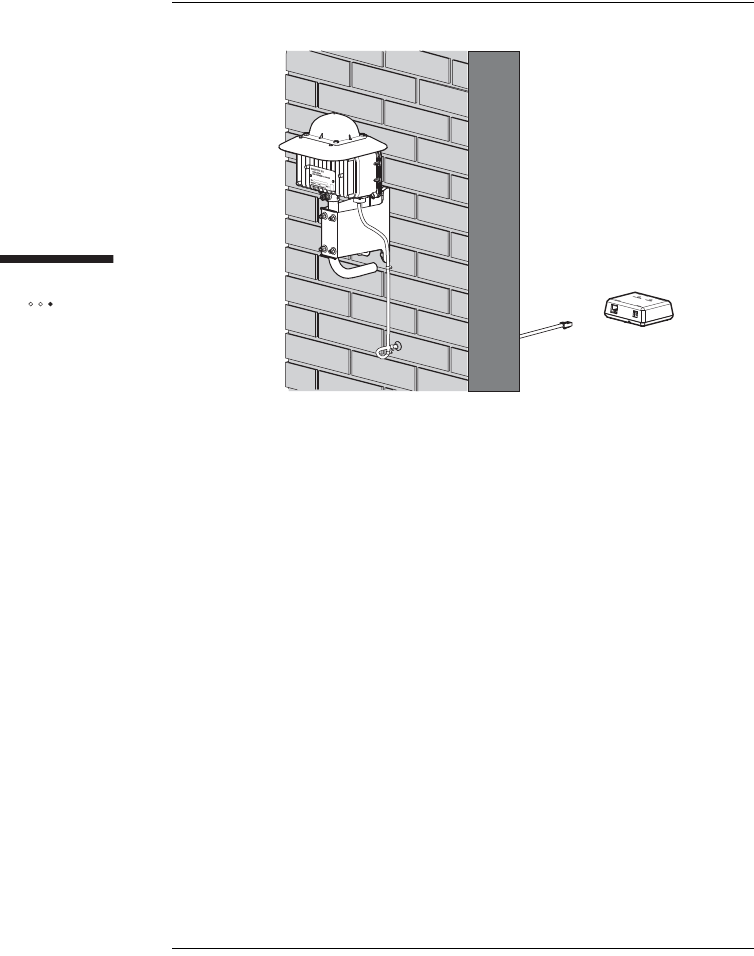
ROUTING CABLE TO
THE INDOOR UNIT
When routing cable to the indoor unit, you should select the shortest possible path
and always protect cable from physical damage.
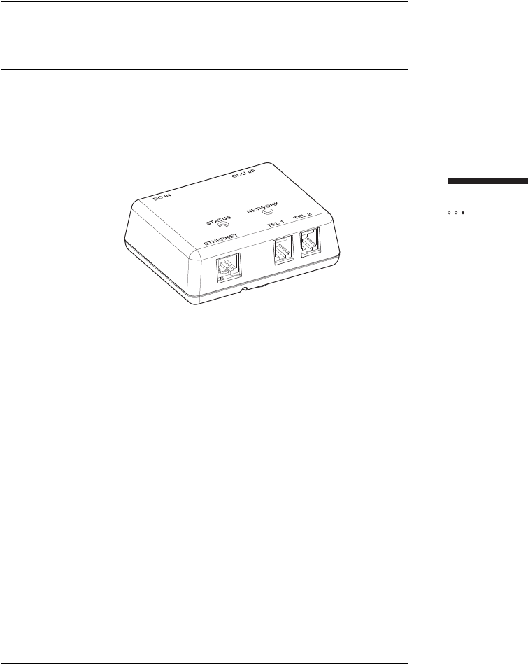
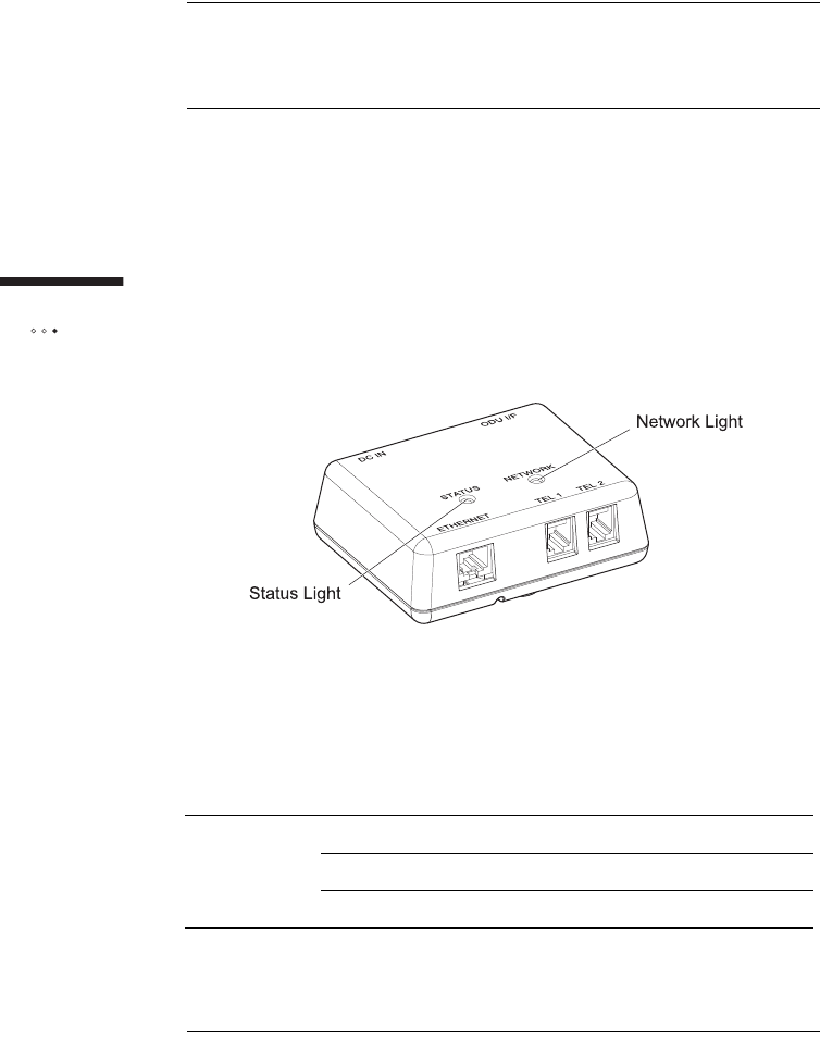
The indoor unit
The figure below shows the location of lights on the top of the indoor unit. The
Status light indicates the indoor unit is energized and the power is supplied to the
outdoor unit. The Status light is off when the SOMAport is powered off. See “Status
light” on page 21 for more information about the status light.
Tools and materials
Make sure you have the following items on hand before you begin.
Materials CAT5 cable
Cable clips
Silicone sealant

105
Installing
t
he indoor unit
To route the CAT5 cable from the outdoor unit to the
indoor unit
1Verify that there are no wires or pipes blocking the location where
you will be feeding the CAT5 cable into the building.
2Drill a hole in the wall where you want the CAT5 cable to enter the
building.
3Cable to the wall using cable clips.
4Make sure the outdoor unit is off.
ATTENTION: The outdoor unit must be off before you connect
the CAT5 cable to it.
5Feed the CAT5 cable into the building through the drilled hole. Add
a loop to the cable before it enters the building.
6Feed the CAT5 cable from the outdoor unit into the ODU I/F port
on the side of the indoor unit.
If you secure the indoor unit onto the wall, insert wood screws (3.1
x 32 mm) into two mount holes in the box and tighten them, then
close the cover. If not, simply close the cover. In case of securing
it onto the wall, ensure that the strength between the indoor unit
and the wall shall be 50 N or above.
Tool Drill with a 10-20 mm drill bit appropriate for the type of
material (such as wood or masonry)
Screwdriver
106
Installing
the indoor unit
7Seal the access point into the building with silicone sealant.
8Turn on the SOMAport. The SOMAport takes a few minutes to
start and connect to the network.
9Test the equipment that is attached to the SOMAport.
107
Installing
t
he indoor unit
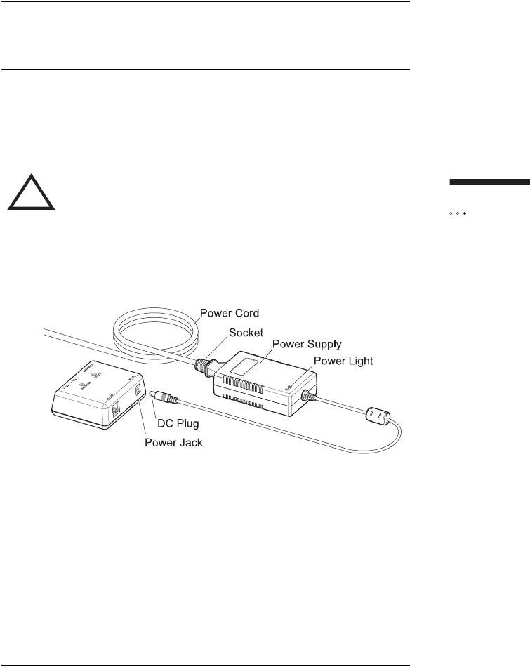
CONNECTING THE POWER SUPPLY
AND POWERING ON THE INDOOR UNIT
The indoor unit does not have a power switch. You turn on the indoor unit by
plugging it into a power outlet, and turn it off by unplugging it. When you plug in
the indoor unit, it starts, connects to your service provider’s network, and tunes itself
(acquires a radio channel).
To install the power supply and power on the indoor unit
1Insert the DC plug into the power jack of the indoor unit.
2Insert the socket end of the power cord into the power supply’s
receptacle.
3Insert the plug end of the power cord into a three-prong grounded
power outlet. The indoor unit powers on when you plug it in. There
is no power button. The light on the power supply turns on if it is
receiving power.
4The SOMAport takes up to five minutes to start, acquire a radio
signal, and connect to the network.
NOTE: If you ever need to disconnect the power supply,
disconnect the power cord from the power outlet first. Then
unplug the connector from the back of the indoor unit.
!WARNING: Use only the power supply and power cord
that came with the indoor unit. Using another power supply
may damage your equipment and poses the risk of shock
or electrocution.

108
Installing
the indoor unit
CONNECTING COMPUTERS AND
TELEPHONES TO THE INDOOR UNIT
For information about connecting a computer, see “Connecting a computer via
Ethernet” on page 25.
For information about connecting telephones, see “Connecting Telephones to the
Indoor Unit" on page 26.

109
A
activating service 30
antenna 19, 22, 61
B
cables
crossover 25, 106
Ethernet 25
calls are dropped 39, 41
C
computer equipment
connecting to a SOMAport
using the Ethernet port 20, 25, 33
connecting
an Ethernet hub 33
computer equipment
using the Ethernet port 20, 25, 33
multiple computers 31, 34
telephones 28
connecting telephones 26
D
dial tone
no 29
dial-up connection 46
E
Ethernet
cables 25
network settings
Mac OS 8 and 9 55
Mac OS X 56
Windows 2000 52
Windows 95 49
Windows 98 or ME 51
Windows XP 54
port 25, 45
F
fault conditions 43
full service
activating 29, 50
H
hub. See Ethernet and LANs
I
Internet
access problems 37
cannot connect to 58
disabling dial-up connection 46
Internet Explorer
LAN settings are incorrect 48
IP address
obtaining automatically
Windows 2000 58
Windows 95 58
Windows 98 and ME 59
Windows XP 59
J
jacks. See telephone jacks and power jack
L
LANsInternet Explorer settings incorrect 48
lights network 106
power 106
M
Mac OS
dial-up connection 46
network settings 55, 56
N
network settings
INDEX

110
changing
Mac OS 8 and 9 55
Mac OS X 56
Windows 2000 52
Windows 95 49
Windows 98 and ME 50
Windows XP 54
O
Outdoor SOMAport. See SOMAport
P
performance 14
ports Ethernet 20
power jack 24, 44, 109
power line 82, 89
power requirements 61
power supply
check 44
connecting 24
disconnect 24
powering on the SOMAport 24
problems
Internet connection 37
R
reception quality 41
restart
computer 50, 51, 53, 55, 56
Outdoor SOMAport 43
restricted access 30
S
safety instructions 11
safety precautions 12
separation distance 22
service modes 30
service providers 18, 22, 24, 26
services
activating 30
servicing 14
settings
Internet Explorer 48
signals
reception 41
strength 41
SOMAport
performance problems 41
restarting 43
SOMAports
connecting Ethernet hubs 33
maintenance and servicing 14
powering on 24
signal strength 41
T
telephone
poor voice quality 39
telephone calls
dropped 39
telephone jacks 20
test telephone service 29
two-line telephones 27, 28
V
voice quality 39, 41
W
warnings 11
Web pages 30
Windows 98
network settings 50
Windows 2000
network settings 52
Windows 95
network settings 49
Windows XP
network settings 54
wireless service provider 18