Sanyo Ks1872 Users Manual
ks2472 Installation_Manual_18KS72_24KS72
2015-01-26
: Sanyo Sanyo-Ks1872-Users-Manual-336249 sanyo-ks1872-users-manual-336249 sanyo pdf
Open the PDF directly: View PDF ![]() .
.
Page Count: 25
85264189988000 © SANYO 2006
In Canada
SANYO FISHER COMPANY SANYO Canada Inc.
A DIVISION OF SANYO NORTH AMERICA CORPORATION 300 Applewood Crescent, Concord
21605 Plummer Street Ontario, L4K 5C7, Canada
Chatsworth, CA 91311 U.S.A.
W
Contents Page
IMPORTANT!
Please Read Before Starting .................................. 2
1. GENERAL .......................................................... 3
1-1. Tools Required for Installation (not supplied)
1-2. Accessories Supplied with Unit
1-3. Optional Copper Tubing Kit
1-4. Type of Copper Tube and Insulation Material
1-5. Additional Materials Required for Installation
2. INSTALLATION SITE SELECTION ................... 4
2-1. Indoor Unit
2-2. Outdoor Unit
2-3. Baffle Plate for the Outdoor Unit
3. HOW TO INSTALL THE INDOOR UNIT ............. 7
3-1. Remove the Rear Panel from the Unit
3-2. Make a Hole
3-3. Install the Rear Panel on the Wall
3-4. Remove the Grille to Install the Indoor Unit
3-5. Shape the Indoor Side Tubing
3-6. Wiring Instructions
3-7. Recommended Wire Length and Diameter
3-8. Wiring Instructions for Inter-unit Connections
3-9. Mounting
3-10. Drain Hose
4. HOW TO INSTALL THE OUTDOOR UNIT ....... 17
4-1. Wiring Instructions for the Outdoor Unit
5. REFRIGERANT TUBING.................................. 18
5-1. Use of the Flaring Method
5-2. Flaring Procedure with a Flare Tool
5-3. Caution before Connecting Tubes Tightly
5-4. Connecting Tubing between Indoor and
Outdoor Units
5-5. Insulation of Refrigerant Tubing
5-6. Taping the Tubes
5-7. Finishing the Installation
6. AIR PURGING................................................... 20
IAir Purging with a Vacuum Pump (for Test Run)
IBasic Functions of the Service Valves
IPump Down
INSTALLATION INSTRUCTIONS
Model Combinations
Combine indoor and outdoor units only as listed
below.
Indoor Unit Outdoor Unit
KS1872 C1872
CL1872
KS2472 C2472
CL2472
Power Source:
60 Hz, single-phase, 230/208 V
– Inverter Split System Air Conditioner – COOL/DRY Model
This air conditioner uses the new refrigerant R410A.
Be sure to read the yellow instruction sheet
attached to the outdoor unit for models using the
new refrigerant R410A.
The illustrations are based on the typical appearance of
a standard model. Consequently, the shape may differ
from that of the air conditioner that you are installing.
NOTE
7. REMOTE CONTROL UNIT INSTALLATION
POSITION ......................................................... 24
7-1. Mounting on a Wall
8. ADDRESS SWITCH.......................................... 25
8-1. Address Setting of the Remote
Control Unit
05-326 AirCon_85264189988000 12/5/05 3:35 PM Page a
2
IMPORTANT!
Please Read Before Starting
This air conditioning system meets strict safety and operating
standards. As the installer or service person, it is an important
part of your job to install or service the system so it operates
safely and efficiently.
For safe installation and trouble-free operation, you
must:
GCarefully read this instruction booklet before beginning.
GFollow each installation or repair step exactly as shown.
GObserve all local, state, and national electrical codes.
GPay close attention to all warning and caution notices
given in this manual.
This symbol refers to a hazard
or unsafe practice which can
result in severe personal injury
or death.
This symbol refers to a hazard
or unsafe practice which can
result in personal injury or prod-
uct or property damage.
If Necessary, Get Help
These instructions are all you need for most installation
sites and maintenance conditions. If you require help for a
special problem, contact our sales/service outlet or your
certified dealer for additional instructions.
In Case of Improper Installation
The manufacturer shall in no way be responsible for improp-
er installation or maintenance service, including failure to
follow the instructions in this document.
SPECIAL PRECAUTIONS
When Wiring
ELECTRICAL SHOCK CAN CAUSE SEVERE
PERSONAL INJURY OR DEATH. ONLY A
QUALIFIED, EXPERIENCED ELECTRICIAN
SHOULD ATTEMPT TO WIRE THIS SYSTEM.
• Do not supply power to the unit until all wiring and tubing
are completed or reconnected and checked.
• Highly dangerous electrical voltages are used in this
system. Carefully refer to the wiring diagram and these
instructions when wiring. Improper connections and
inadequate grounding can cause accidental injury or
death.
• Ground the unit following local electrical codes.
• Connect all wiring tightly. Loose wiring may cause over-
heating at connection points and a possible fire hazard.
When Transporting
Be careful when picking up and moving the indoor and out-
door units. Get a partner to help, and bend your knees when
lifting to reduce strain on your back. Sharp edges or thin alu-
minum fins on the air conditioner can cut your fingers.
When Installing…
…In a Ceiling or Wall
Make sure the ceiling/wall is strong enough to hold the
unit’s weight. It may be necessary to construct a strong
wood or metal frame to provide added support.
…In a Room
Properly insulate any tubing run inside a room to prevent
“sweating” that can cause dripping and water damage to
walls and floors.
…In Moist or Uneven Locations
Use a raised concrete pad or concrete blocks to provide a
solid, level foundation for the outdoor unit. This prevents
water damage and abnormal vibration.
…In an Area with High Winds
Securely anchor the outdoor unit down with bolts and a
metal frame. Provide a suitable air baffle.
…In a Snowy Area (for Heat Pump-type Systems)
Install the outdoor unit on a raised platform that is higher
than drifting snow. Provide snow vents.
When Connecting Refrigerant Tubing
• Use the flare method for connecting tubing.
• Apply refrigerant lubricant to the matching surfaces of
the flare and union tubes before connecting them, then
tighten the nut with a torque wrench for a leak-free
connection.
• Check carefully for leaks before starting the test run.
When Servicing
• Turn the power OFF at the main power box (mains) before
opening the unit to check or repair electrical parts and
wiring.
• Keep your fingers and clothing away from any moving
parts.
• Clean up the site after you finish, remembering to check
that no metal scraps or bits of wiring have been left inside
the unit being serviced.
Others
• Ventilate any enclosed areas when installing or testing
the refrigeration system. Escaped refrigerant gas, on
contact with fire or heat, can produce dangerously
toxic gas.
• Confirm upon completing installation that no refrigerant
gas is leaking. If escaped gas comes in contact with a
stove, gas water heater, electric room heater or other heat
source, it can produce dangerously toxic gas.
WARNING
WARNING
CAUTION
CAUTION
05-326 AirCon_85264189988000 12/5/05 3:35 PM Page 2
3
1. General
This booklet briefly outlines where and how to install the
air conditioning system. Please read over the entire set
of instructions for the indoor and outdoor units and make
sure all accessory parts listed are with the system before
beginning.
1-1. Tools Required for Installation (not supplied)
1. Standard screwdriver
2. Phillips head screwdriver
3. Knife or wire stripper
4. Tape measure
5. Carpenter’s level
6. Sabre saw or key hole saw
7. Hacksaw
8. Core bits
9. Hammer
10. Drill
11. Tube cutter
12. Tube flaring tool
13. Torque wrench
14. Adjustable wrench
15. Reamer (for deburring)
1-2. Accessories Supplied with Unit
Table 1
1-3. Optional Copper Tubing Kit
Copper tubing for connecting the outdoor unit to the
indoor unit is available in kits which contain the narrow
and wide tubing, fittings and insulation. Consult your
nearest sales outlet or A/C workshop.
1-4. Type of Copper Tube and Insulation Material
If you wish to purchase these materials separately from
a local source, you will need:
1. Deoxidized annealed copper tube for refrigerant tub-
ing as detailed in Table 2.
Cut each tube to the appropriate lengths 1' to 1'4"
(30 cm to 40 cm) to dampen vibration between units.
Table 2
2. Foamed polyethylene insulation for the specified
copper tubes as required to precise length of tubing.
Wall thickness of the insulation should be not less
than 5/16" (8 mm).
3. Use insulated copper wire for field wiring. Wire size
varies with the total length of wiring. Refer to 3-6.
Wiring Instructions for details.
PartsFigure Q’ty PartsFigure Q’ty
1
1
2
Rawl plug
Tapping screw Hex wrench*
Truss-head
Phillips
5/32 ¥ 5/8" (4¥16 mm)
1
2
AAA alkaline
battery
10
8
1
PartsFigure Q’ty
Remote
control unit
Remote control
unit holder
Air clean filter
1
*Packed in the outdoor unit.
Clamp
Drain hose
adapter
Cushion
rubber*4
CAUTION Check local electrical codes
and regulations before
obtaining wire. Also, check
any specified instructions or
limitations.
Model Narrow Tube Wide Tube
Outer Dia. Thickness Outer Dia. Thickness
KS1872 1/4" (6.35 mm) 0.0314" (0.8 mm) 1/2" (12.70 mm) 0.0314" (0.8 mm)
KS2472 1/4" (6.35 mm) 0.0314" (0.8 mm) 5/8" (15.88 mm) 0.0393" (1.0 mm)
05-326 AirCon_85264189988000 12/5/05 3:35 PM Page 3
4
1-5. Additional Materials Required for Installation
1. Refrigeration (armored) tape
2. Insulated staples or clamps for connecting wire
(See local codes)
3. Putty
4. Refrigeration lubricant
5. Clamps or saddles to secure refrigerant tubing
2. Installation Site Selection
2-1. Indoor Unit
AVOID:
Gdirect sunlight.
Gnearby heat sources that may affect performance of the unit.
Gareas where leakage of flammable gas may be expected.
Gplaces where large amounts of oil mist exist.
DO:
Gselect an appropriate position from which every corner of
the room can be uniformly cooled. (High on a wall is best.)
Gselect a location that will hold the weight of the unit.
Gselect a location where tubing and drain hose have the
shortest run to the outside. (Fig. 1)
Gallow room for operation and maintenance as well as unre-
stricted air flow around the unit. (Fig. 2)
Ginstall the unit within the maximum elevation difference (H)
above or below the outdoor unit and within a total tubing length
(L) from the outdoor unit as detailed in Table 3 and Fig. 3a.
GInstall the indoor unit more than 3.3' (1 m) away from any
antenna or power lines or connecting wires used for television,
radio, telephone, security system, or intercom. Electrical noise
from any of these sources may affect operation.
Drain hose
Indoor unit
Outside drainage
Fig. 1
2" (5 cm)
min.
6" (15 cm)
min.
Front View
2" (5 cm)
min.
Fig. 2
INDOOR
UNIT
Tubing length (L)
OUTDOOR
UNIT
Elevation
difference (H)
Fig. 3a
WARNING To prevent abnormal heat genera-
tion and the possibility of fire, do
not place obstacles, enclosures
and grilles in front of or surround-
ing the air conditioner in a way
that may block air flow.
*If total tubing length becomes 25 to 98 ft. (Max.) or 33 to 131 ft. (Max.), charge additional refrigerant (R410A) by 0.27 oz./ft.
No additional charge of compressor oil is necessary.
Indoor unit
Floor level
Wall
Minimum height
from floor level
5' (1.5 m)
Fig. 3b
For stable operation of the
air conditioner, do not
install wall-mounted type
indoor units less than 5'
(1.5 m) from floor level.
CAUTION
Max. Allowable Tubing Limit of Tubing Limit of Elevation Required Amount of
Model Length at Shipment Length (L) Difference (H) Additional Refrigerant
(ft.) (ft.) (ft.) (oz./ft.)*
KS1872 25 98 49 0.27
KS2472 33 131 49 0.27
Table 3
05-326 AirCon_85264189988000 12/5/05 3:35 PM Page 4
5
2-2. Outdoor Unit
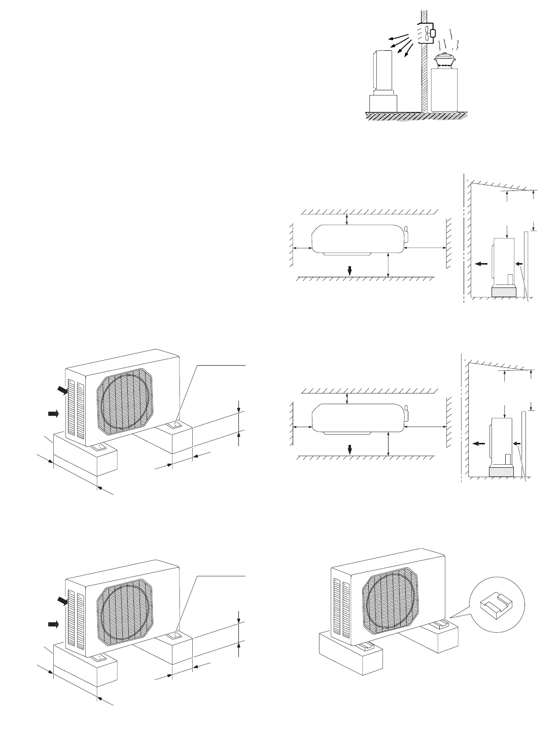
AVOID:
Gheat sources, exhaust fans, etc. (Fig. 4)
Gdamp, humid or uneven locations.
DO:
Gchoose a place as cool as possible.
Gchoose a place that is well ventilated.
Gallow enough room around the unit for air intake/
exhaust and possible maintenance. (Fig. 5a or 5b)
Gprovide a solid base (level concrete pad, concrete block,
4" ¥1'4" (10 ¥40 cm) or 6" ¥1'4" (15 ¥40 cm) beams
or equal), a minimum of 4" (10 cm) or 6" (15 cm) above
ground level to reduce humidity and protect the unit
against possible water damage and decreased service
life. (Fig. 5c or 5d)
GInstall cushion rubber under unit’s feet to reduce
vibration and noise. (Fig. 5e)
Guse lug bolts or equal to bolt down unit, reducing
vibration and noise.
GInstall in a location where no antenna of a television
or radio exists within 10' (3 m).
Outdoor unit
Hot air
Heat source
Exhaust fan
NO
Fig. 4
Fig. 5c
Air intake Min. 4" (10 cm)
Air discharge
Min.
2" (5 cm) Min.
1'4" (40 cm)
Valve
side
Min. 10"
(25 cm)
Min.
7' (2 m)
Min.
7' (2 m)
Ground
Obstacle
Obstacle above
Air discharge
Min. 4" (10 cm
)
Air intake
Air intake
Concrete
or equal
About 4" (10 cm)
Min. 4" (10 cm)
Anchor bolts
(4 pcs.)
About 1'4" (40 cm)
Fig. 5e
Cushion rubber
Fig. 5a
(C1872, CL1872)
Air intake Min. 8" (20 cm)
Air discharge
Min.
4" (10 cm) Min.
1'8" (50 cm)
Valve
side
Min. 10"
(25 cm)
Min.
7' (2 m)
Min.
7' (2 m)
Ground
Obstacle
Obstacle above
Air discharge
Min. 8" (20 cm)
Air intake
Fig. 5b
(C2472, CL2472)
(C1872, CL1872)
Fig. 5d
Air intake
Concrete
or equal
About 6" (15 cm)
Min. 6" (15 cm)
Anchor bolts
(4 pcs.)
About 1'4" (40 cm)
(C2472, CL2472)
05-326 AirCon_85264189988000 12/5/05 3:35 PM Page 5
6
2-3. Baffle Plate for the Outdoor Unit
(CLxx models only)
It is recommended to use baffle plates for models
CL1872 and CL2472. The baffle plates are not normally
required for the other models.
When the outdoor unit is installed in a position exposed
to strong wind (like seasonal winds with low air tempera-
ture in winter), baffle plates must be installed in front of
the outdoor unit. (Fig. 5f)
This unit is designed so that the fan of the outdoor unit
runs at low speed when the air conditioner is operated at
low outdoor air temperatures. When the outdoor unit is
exposed to strong wind, the system pressure drops
because of the freeze protector.
NOTE
Fig. 5f
Air discharge
6" min
Air discharge
6" min
Baffle
plate Baffle
plate
05-326 AirCon_85264189988000 12/5/05 3:35 PM Page 6
7
Set screw only for transportation
Fig. 6
Rear panel
marks
Fig. 7
Left
tubing
Right tubing
Downward tubing
Right-rear
tubing
(recommended)
Left-rear
tubing
Fig. 8
3. How to Install the Indoor Unit
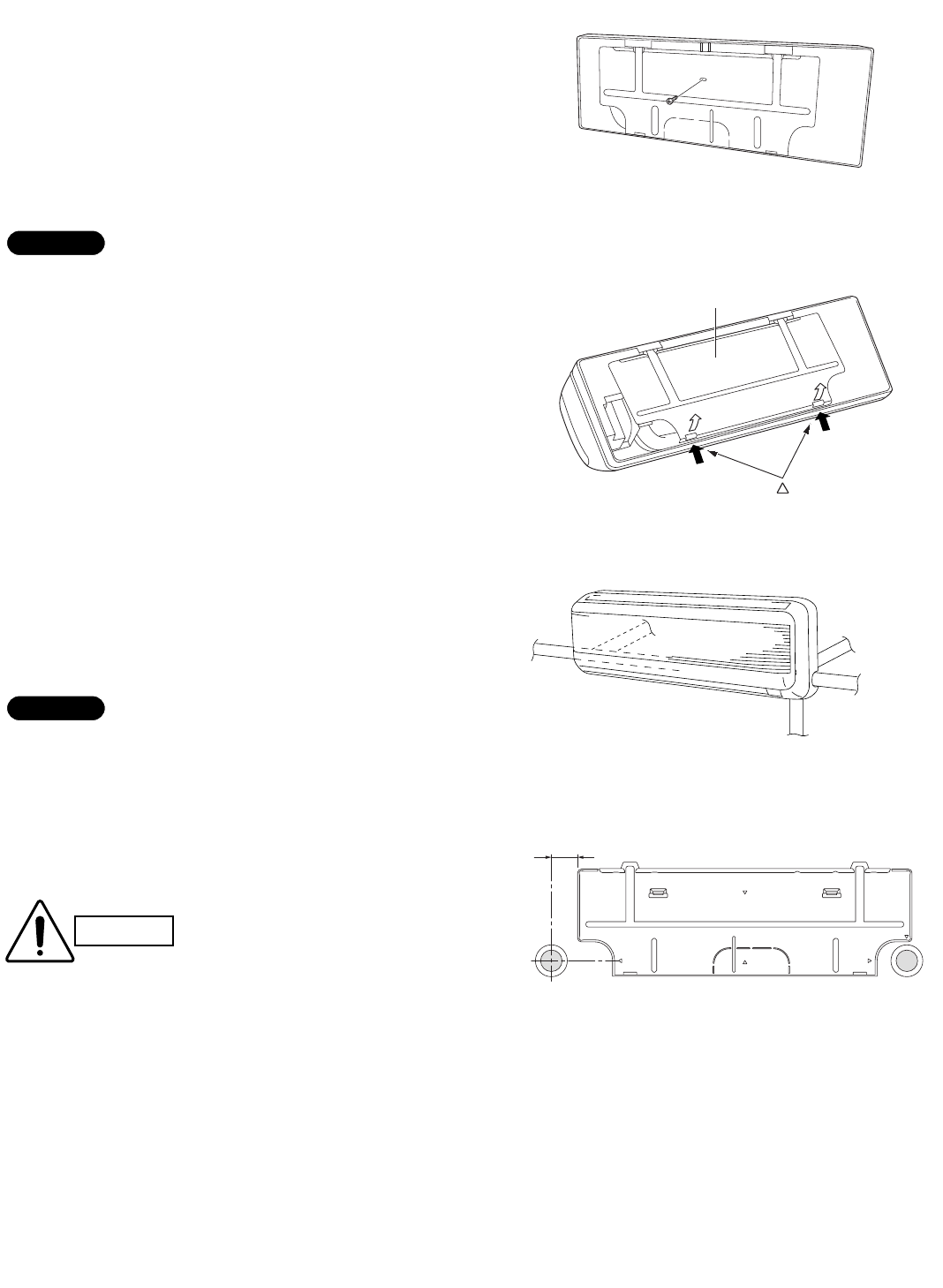
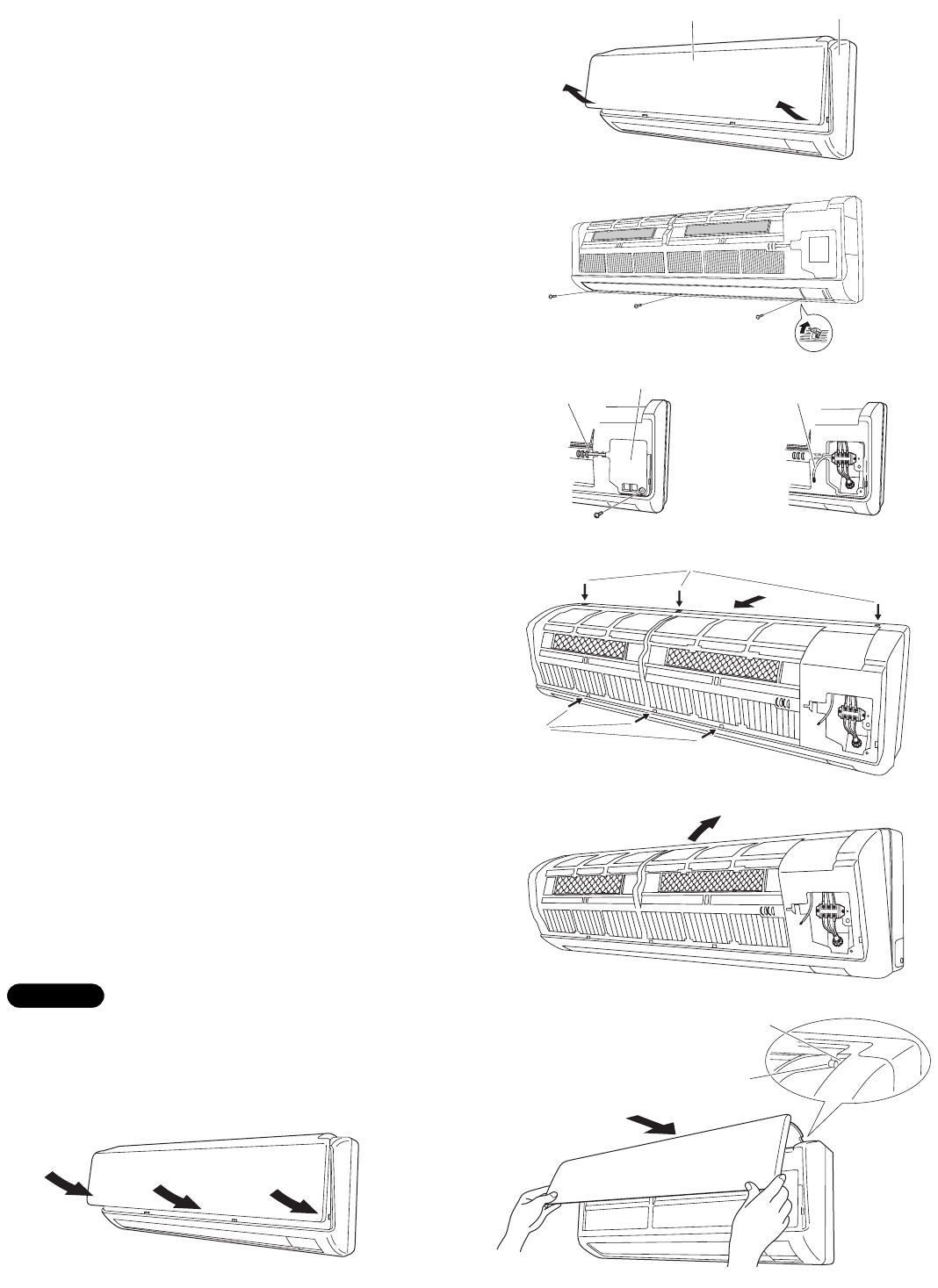
3-1. Remove the Rear Panel from the Unit
(1) Remove and discard the set screw on the rear
panel. (Fig. 6)
(2) Press the 2 LLmarks on the frame cover and disen-
gage the stationary tabs from the frame. (Fig. 7)
(3) Remove the rear panel.
Tubing can be extended in 5 directions as shown in Fig.
8. Select the direction you need providing the shortest
run to the outside unit.
GWhen left tubing is to be done, switch the drain hose
and drain cap. (For details, refer to “Switching drain
hose and drain cap” on page 14.)
3-2. Make a Hole
(1) Place the rear panel from the indoor unit on the wall
at the location selected. Make sure the panel is hori-
zontal, using a carpenter’s level or tape measure to
measure down from the ceiling. Wait until after cut-
ting the hole before attaching the rear panel to the
wall.
(2) Determine which side of the unit you should make
the hole for tubing and wiring. (Fig. 9)
In the case of left-rear tubing, use the measurement
points 2-3/8" (60 mm) from the edge of the rear panel for
precise placement of the hose outlet. (Fig. 9)
(3) Before making the hole, check carefully that no
studs or pipes are directly run behind the spot to be
cut.
The above precautions are also applicable if tubing
goes through the wall in any other location.
NOTE
NOTE
2-3/8" (60 mm)
Fig. 9
CAUTION Also avoid areas where elec-
trical wiring or conduits are
located.
05-326 AirCon_85264189988000 12/5/05 3:35 PM Page 7
8
Indoor
side
Outdoor
side
Hole should be made at a slight downward slant to the
outdoor side.
NOTE
Fig. 10
Plastic cover
INSIDE OUTSIDE
Wall
Slight
angle
PVC pipe
(Locally purchased)
Fig. 12
PVC pipe (Locally purchased)
Cut at sli
g
ht an
g
le
Fig. 11
(4) Using a sabre saw, key hole saw or hole-cutting drill
attachment, cut a hole in the wall. See Table 4 and
Fig. 10.
Table 4
(5) Measure the thickness of the wall from the inside
edge to the outside edge and cut PVC pipe at a
slight angle 1/4" (6 mm) shorter than the thickness of
the wall. (Fig. 11)
(6) Place the plastic cover over the end of the pipe (for
indoor side only) and insert the pipe in the wall. (Fig.
12)
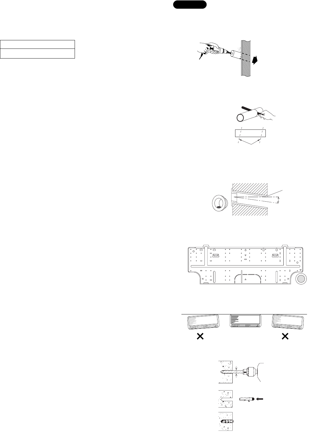
3-3. Install the Rear Panel on the Wall
Be sure to confirm that the wall is strong enough to sus-
pend the unit.
See either Item a) or b) below depending on the wall type.
a) If Wooden Wall
(1) Attach the rear panel to the wall with the 8 screws
provided. (Fig. 13)
If you are not able to line up the holes in the rear
panel with the beam locations marked on the wall,
use rawl plugs or toggle bolts to go through the
holes on the panel or drill 3/16" (5 mm) dia. holes in
the panel over the stud locations and then mount the
rear panel.
(2) Double check with a carpenter’s level or tape mea-
sure that the panel is level. This is important to
install the unit properly. (Fig. 14)
(3) Make sure the panel is flush against the wall. Any
space between the wall and unit will cause noise
and vibration.
b) If Block, Brick, Concrete or Similar Type Wall
Make 3/16" (4.8 mm) dia. holes in the wall. Insert rawl
plugs for appropriate mounting screws. (Fig. 15)
Hole Dia.
3-5/32" (80 mm)
Fig. 13
Fig. 14
3/16"
(4.8 mm) dia. hole
Rawl plug
Fig. 15
05-326 AirCon_85264189988000 12/5/05 3:35 PM Page 8
9
3-4. Remove the Grille to Install the Indoor Unit
Basically, these models can be installed and wired with-
out removing the grille. If access to any internal part is
needed, follow the steps as given below.
How to remove the grille
(1) Grasp both ends of the air intake grille, and remove
it by opening towards the front and pulling towards
you. (Fig. 16a)
(2) Remove the 3 screws. (Fig. 16b)
(3) Remove the screw on the right side cover plate and
open the cover. (Fig. 17a)
(4) Take out the thermistor from the grille. (Fig. 17b)
(5) Press the 3 tabs at the top of the grille and the 3
tabs on the front face to separate the grille from the
frame. (Fig. 18a)
(6) Pull the grill toward you to remove it.
How to replace the grille
(1) When installing the grille, place the bottom of the
grille into the frame first. (Fig. 18b)
Then insert the tabs on the top of the grille and on
the front face into the frame.
(2) Make sure that the grille and frame are firmly fitted
together by engaging the tabs.
(3) Attach the thermistor on the grille. (Fig. 17a)
(4) Close the cover and replace the screw. (Fig. 17a)
(5) Affix the grille with the 3 previously removed screws.
(Fig. 16b)
(6) Install the air intake grille.
(a) Allow the edge of the air intake grille to slide into the
top of the indoor unit, and then insert it all the way
inside. (Fig. 19a)
(b) Press the bottom right and left corners and center of
the air intake grille to attach it to the indoor unit.
(Fig. 19b)
Attach so that the round pins at the top right and left cor-
ners of the air intake grille are inserted into the grooves
at the top right and left of the indoor unit.
NOTE
Air intake grille Grille
Fig. 16a
Fig. 16b
Cover
Thermistor
Fig. 17a
Thermistor
Fig. 17b
Fig. 18a
Tab
Tab
Fig. 18b
Fig. 19b
Pin
Groove
Fig. 19a
05-326 AirCon_85264189988000 12/5/05 3:35 PM Page 9
10
3-5. Shape the Indoor Side Tubing
(1) Arrangement of tubing by direction
a) Right or left tubing
Cut out the corner of the right/left frame with a
hacksaw or the like. (Figs. 20 and 21)
b) Right-rear or left-rear tubing
In this case, the corner of the frame need not be
cut.
(2) To mount the indoor unit on the rear panel:
Hang the 2 mounting slots of the unit on the
upper tabs of the rear panel. (Fig. 22)
3-6. Wiring Instructions
General precautions on wiring
(1) Before wiring, confirm the rated voltage of the unit as
shown on its nameplate, then carry out the wiring
closely following the wiring diagram.
(2) Provide a power outlet to be used exclusively for
each unit, with a power supply disconnect and cir-
cuit breaker for overcurrent protection provided in
the exclusive line.
(3) To prevent possible hazards due to insulation failure,
the unit must be grounded.
(4) Each wiring connection must be done tightly and in
accordance with the wiring system diagram. Wrong
wiring may cause the unit to misoperate or become
damaged.
(5) Do not allow wiring to touch the refrigerant tubing,
compressor, or any moving parts of the fan.
(6) Unauthorized changes in the internal wiring can be
very dangerous. The manufacturer will accept no
responsibility for any damage or misoperation that
occurs as a result of such unauthorized changes.
Frame
Right tubing
outlet
Frame
Left tubing
outlet
Fig. 21
Fig. 22
Fig. 20
05-326 AirCon_85264189988000 12/5/05 3:35 PM Page 10
11
(A)+(B) (A) Power Supply Wiring Length (ft) (C) Control Fuse or Circuit AWG (B) Power Line Length (ft) Line Length (ft)
Model (#14) (#12) (#14) Breaker Capacity
C1872, C2472, CL1872, CL2472
131 (Max.) 230 (Max.) 65 (Max.) 20A
3-7. Recommended Wire Length and Diameter
Regulations on wiring diameter differ from locality to locality. For field wiring
requirements, please refer to your local electrical codes. Carefully observe these
regulations when carrying out the installation.
Table 5 lists recommended wire lengths and diameters for power supply systems.
Refer to the wiring system diagram (Fig. 23) for the meaning of (A), (B), and (C) in
Table 5.
Refer to your local codes or in the absence of local codes see the National Elec-
tric Code: ANSI/NFPA70.
NOTE
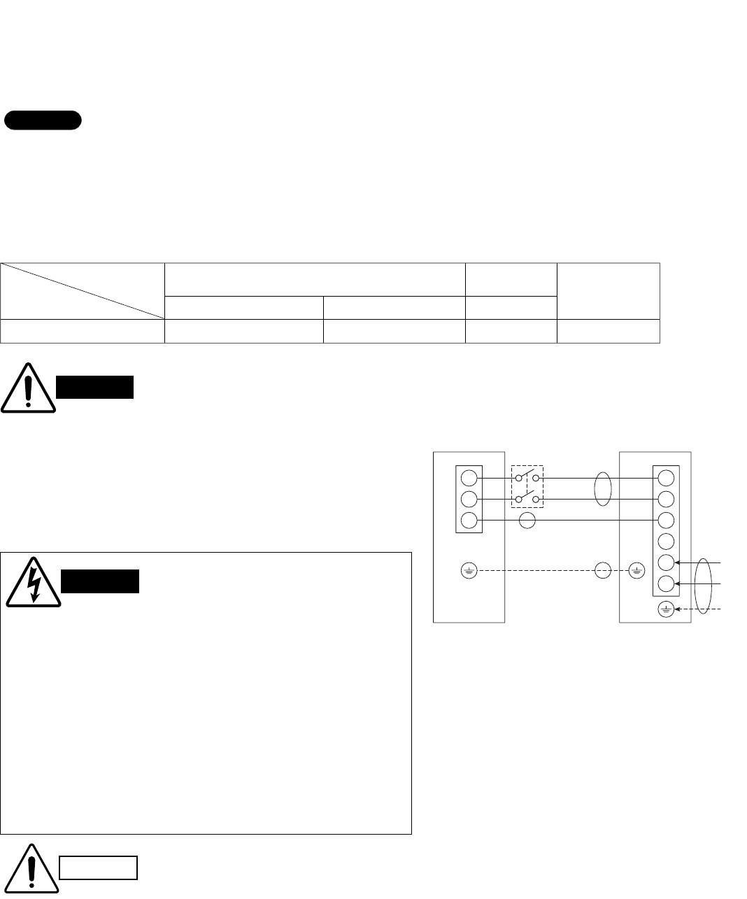
Fig. 23
WIRING SYSTEM DIAGRAM
WARNING
GBe sure to comply with local codes on running the wire
from the indoor unit to the outdoor unit (size of wire and
wiring method, etc.).
GEach wire must be firmly connected.
GNo wire should be allowed to touch refrigerant tubing, the
compressor, or any moving part.
Disconnect
switch
1
2
3
1
2
3
4
5
6
Grounding line
230/208V
230/208V
230/208V
INDOOR
UNIT OUTDOOR
UNIT
Field supply
Grounding
line
L1
L2
Power supply
Single phase 230/208V 60HZ
Ter minal Terminal
(A)
(B)
(C)
(B)
CAUTION
GBe sure to connect the power supply line to the outdoor unit as shown in the wiring diagram.
The indoor unit draws its power from the outdoor unit.
GDo not run wiring for antenna, signal, or power lines of television, radio, stereo, telephone,
security system, or intercom any closer than 3'4" (1 m) from the power cable and wires
between the indoor and outdoor units. Electrical noise may affect the operation.
GTo avoid the risk of electric shock, each air conditioner
unit must be grounded.
GFor the installation of a grounding device, please
observe local electrical codes.
GGrounding is necessary, especially for units using
inverter circuits, in order to release charged electricity
and electrical noise caused by high tension.
Otherwise, electrical shock may occur.
GPlace a dedicated ground more than 7' (2 m) away from
other grounds and do not have it shared with other elec-
tric appliances.
WARNING
# ... AWG (American Wire Gauge)
Table 5
05-326 AirCon_85264189988000 12/5/05 3:35 PM Page 11
12
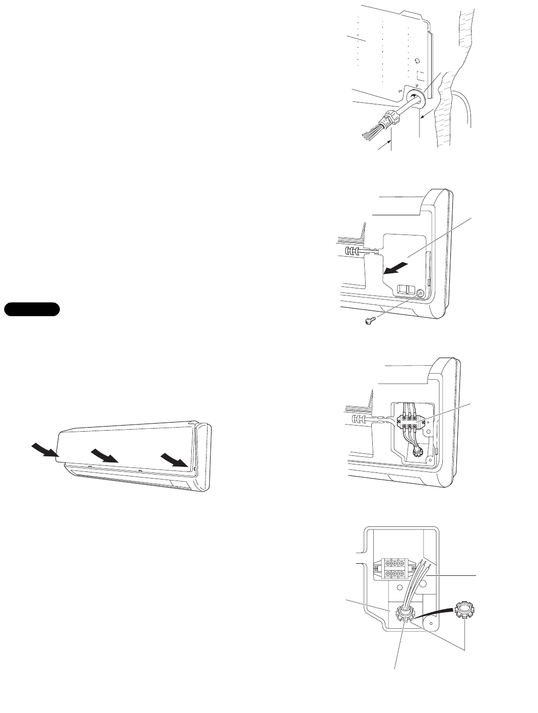
3-8. Wiring Instructions for Inter-unit Connections
(1) Insert the inter-unit wiring (according to local codes)
into the through-the-wall PVC pipe. Run the wiring
toward the indoor side allowing approx. 10" (25 cm)
to extend from the wall face. (Fig. 24)
(2) Grasp both ends of the air intake grille, and remove
it by opening towards the front and pulling towards
you.
(3) Remove the screw on the right side cover plate and
open the cover. (Fig. 25)
(4) Route the inter-unit wiring from the back of the
indoor unit and pull it toward the front for connec-
tion. (Fig. 26a, 26b)
(5) Connect the inter-unit wiring to the corresponding
terminals on the terminal plate (Fig. 26a, 26b) while
referring to the wiring diagram.
(6) Be sure to secure the wiring with the provided
clamp.
When closing the air intake grille, press the bottom right
and left corners and center. (Fig. 27)
Please refer to “How to replace the grille” on page 9 for
installing the air intake grille.
NOTE
Rear
panel
Wiring
Wall
10"
(25 cm)
Plastic
cover
Fig. 24
Cover
Fig. 25
Ter minal
plate
Fig. 26a
Inter-unit
wiring
Lock nut
Earth
plate
Top of conduit
connector
Fig. 26b
Fig. 27
05-326 AirCon_85264189988000 12/5/05 3:35 PM Page 12
13
When connecting each power wire to the corresponding
terminal, follow the instructions “How to connect wiring
to the terminal” and fasten the wire securely tight with
the fixing screw of the terminal plate.
How to connect wiring to the terminal
a) For Indoor Unit
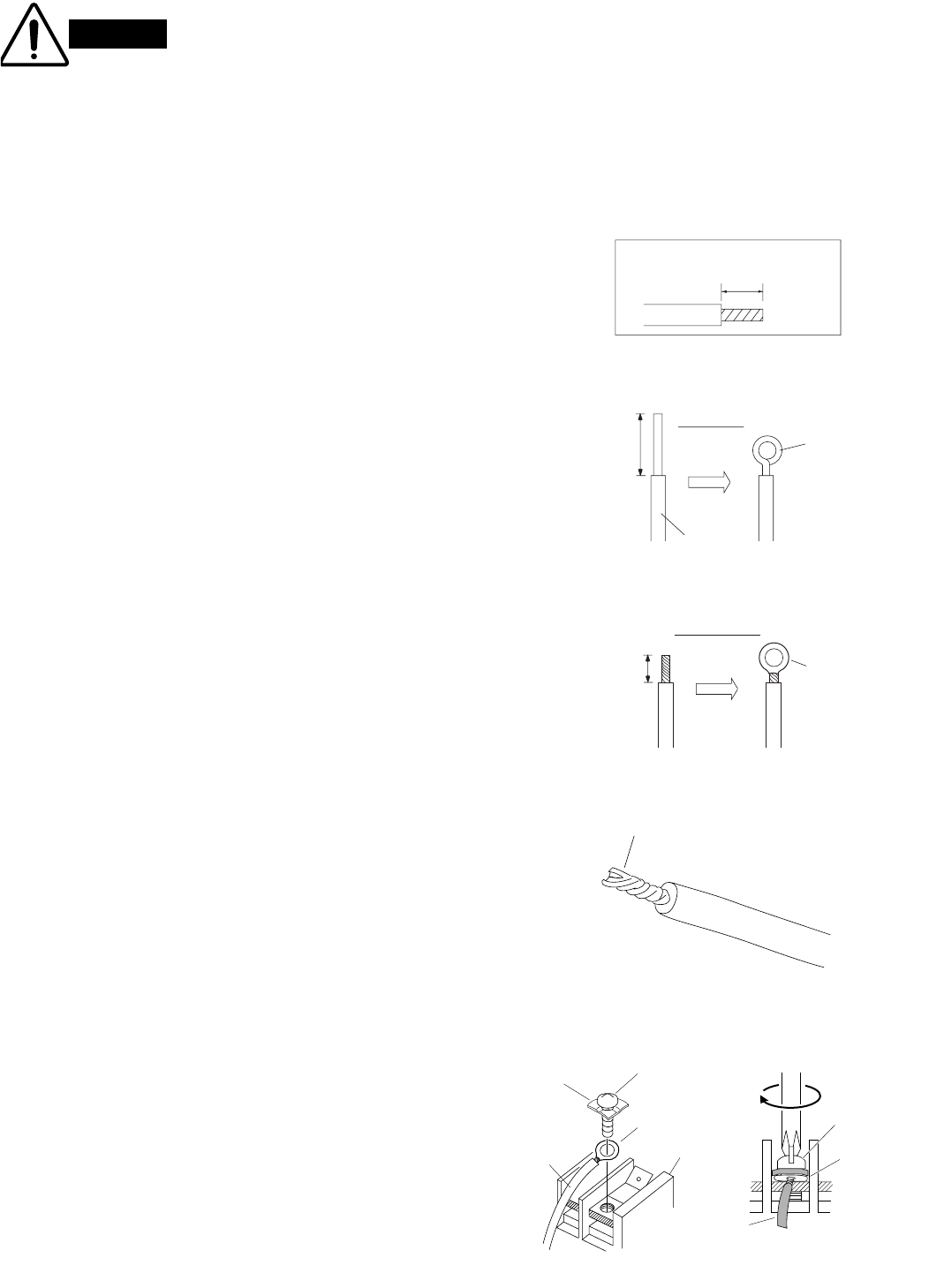
(1) Cut the wire end with a cutting pliers, then strip the
insulation to expose the wire about 9/32" (7 mm).
See the label (Fig. 28) near the terminal plate.
(2) Using a screwdriver, loosen the terminal screw on
the terminal plate.
(3) Insert the wire and tighten the terminal screw com-
pletely using a screwdriver.
b) For Outdoor Unit
IFor solid core wiring (or F-cable)
(1) Cut the wire end with a cutting pliers, then strip the
insulation to expose the solid wire about 15/16" (25
mm). (Fig. 29)
(2) Using a screwdriver, remove the terminal screw(s)
on the terminal plate.
(3) Using the pliers, bend the solid wire to form a loop
suitable for the terminal screw.
(4) Shape the loop wire properly, place it on the termi-
nal plate and fix it securely with the removed termi-
nal screw using a screwdriver.
IFor stranded wiring
(1) Cut the wire end with a cutting pliers, then strip the
insulation to expose the stranded wiring about 3/8"
(10 mm) and tightly twist the wire ends. (Figs. 30
and 31)
(2) Using a screwdriver, remove the terminal screw(s)
on the terminal plate.
(3) Using a ring connector fastener or pliers, securely
clamp each stripped wire end with a ring connector.
(Fig. 30)
(4) Place the ring connector wire, and replace and
tighten the removed terminal screw using a screw-
driver. (Fig. 32)
Solid wire
Loop
Insulation
Strip 15/16" (25 mm)
Fig. 29
STRIP
SIZE
9/32"
(7 mm)(ACTUAL
SIZE)
Fig. 28
Stranded wire
Ring
connector
Strip 3/8" (10 mm)
Fig. 30
Screw
Ring connector
Terminal plate
Wire
Special
washer
Fig. 32
Screw and
special washer
Ring
connector
Wire
WARNING Loose wiring may cause the
terminal to overheat or result
in unit malfunction. A fire
hazard may also exist. There-
fore, be sure all wiring is
tightly connected.
Twist wire ends
Fig. 31
05-326 AirCon_85264189988000 12/5/05 3:35 PM Page 13
14
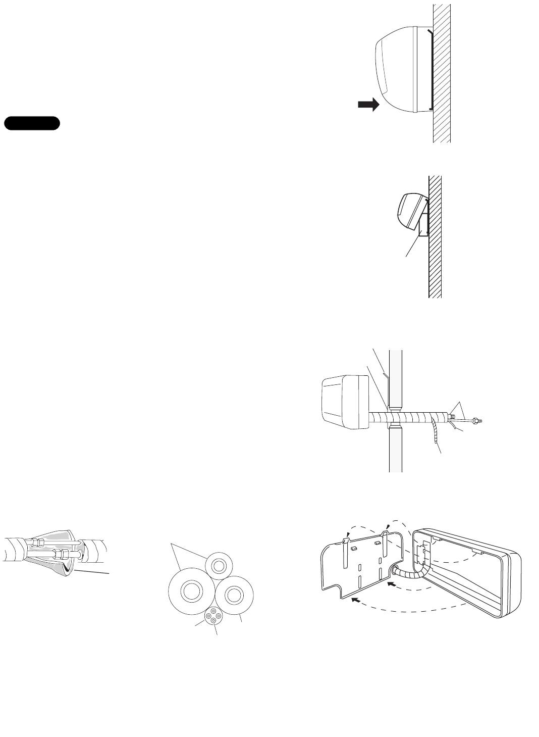
3-9. Mounting
(1) To install the indoor unit, mount the indoor unit onto
the 2 tabs on the upper part of the rear plate.
(2) Hold down the air discharge outlet and press the
lower part of the indoor unit until it clicks to securely
fasten to the 2 tabs on the lower part of the rear
plate. (Fig. 33)
For tubing, choose either the right or left tubing direction
and follow the steps below. This work can be made easi-
er by placing padding material (such as styrofoam) at the
rear right side of the indoor unit. (Fig. 34)
IRight-side tubing
(1) Shape the refrigerant tubing so that it can easily go
into the wall hole. (Fig. 35)
(2) Push the wiring, refrigerant tubing, and drain hose
through the hole in the wall. Adjust the indoor unit so
it is securely seated on the rear panel. (Fig. 36)
(3) Carefully bend the tubing (if necessary) to run along
the wall in the direction of the outdoor unit and then
tape as far as the fittings. (See Caution on page
18.) The drain hose should come straight down the
wall to a point where water runoff won’t stain the
wall.
(4) Connect the refrigerant tubing to the outdoor unit.
(After performing a leak test on the connecting part,
insulate it with the tubing insulation. (Fig. 37a)) Also,
refer to Section 5-4. Connecting Tubing between
Indoor and Outdoor Units.
(5) Assemble the refrigerant tubing, drain hose, and
conduit (including inter-unit wiring) as shown in
Fig. 37b.
NOTE
Cover
Refrigerant
tubing
Rear panel
Drain hose
Inter-unit
wiring
Fig. 35
Fig. 36
Fig. 33
Push
Fig. 34
Insulation
Fig. 37a
Fig. 37b
Refrigerant tubing
Drain hose
Conduit
Inter-unit wiring
Padding material
05-326 AirCon_85264189988000 12/5/05 3:35 PM Page 14
15
Hole in wall
Bent part
Narrow tube
Wide tube
Rear panel
Fig. 38
Drain cap
Drain hose
Fig. 39
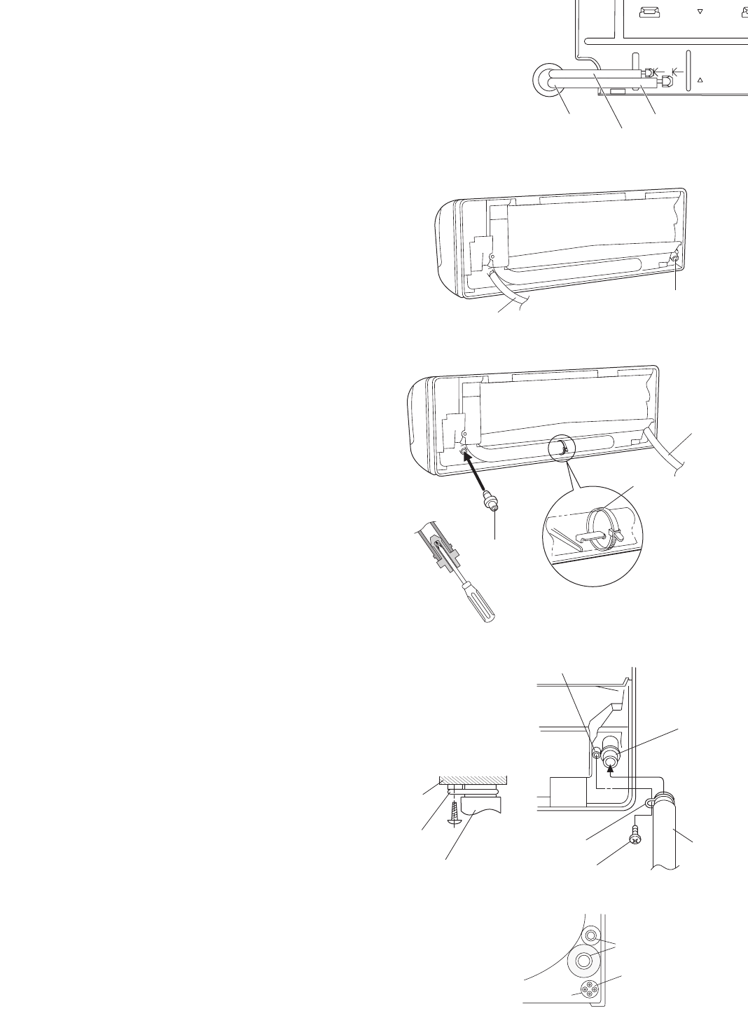
ILeft-side tubing
(1) Lead the tubing and drain hose through the wall,
allowing sufficient length for connection. Then bend
the tubing using a tube bender to make the attach-
ment. (Fig. 38)
(2) Switch the drain hose and drain cap.
Switching drain hose and drain cap
(a) Locate the drain hose and the drain cap. (Fig.
39)
(b) Remove the screws fastening the drain hose on
the right side, and pull out the drain hose to
remove it. (Fig. 39)
(c) Apply moderate force to pull off the drain cap
on the left side. (If you cannot pull it off by
hand, use a long-nose pliers.)
(d) Reattach the drain hose to the left side and the
drain cap to the right side. (Fig. 40a)
Drain hose
Slide the drain hose fully onto the drain pan outlet
until the drain hose edge is pushed into the insula-
tion. Check that the screw holes in the drain bracket
and the drain pan outlet are aligned and securely in
contact, then fasten them with the screw. (After
attaching the drain hose, check that it is attached
securely.) (Fig. 40c)
Drain cap
Use a Phillips screwdriver to push the drain cap in
firmly. (If it is difficult to push in, wet the cap with
water first.)
(3) Install the indoor unit on the rear panel.
(4) Connect the tubing and wiring led inside from out-
doors.
(5) After completing a leak test, bundle the tubing
together with armoring tape and store it inside the
tubing storage area at the back of the indoor unit
and hold it with clamps. (Figs. 40a and 41)
Fig. 40a
Fig. 40b
Fig. 40c
Fig. 41
Refrigerant tubing
Inter-unit wiring
Conduit
Screw
Drain hose
Drain pan outlet
Screw hole
Drain bracket
Drain cap
Clamp
Drain hose
Drain hose
Drain bracket
Insulation
05-326 AirCon_85264189988000 12/5/05 3:35 PM Page 15
16
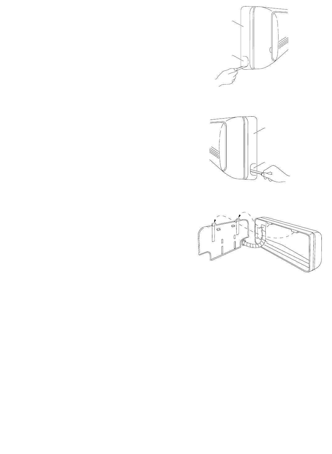
To unmount indoor unit
Press the 2 LLmarks on the lower part of the indoor unit
and unlatch the tabs. Then lift the indoor unit and
unmount. (Fig. 42)
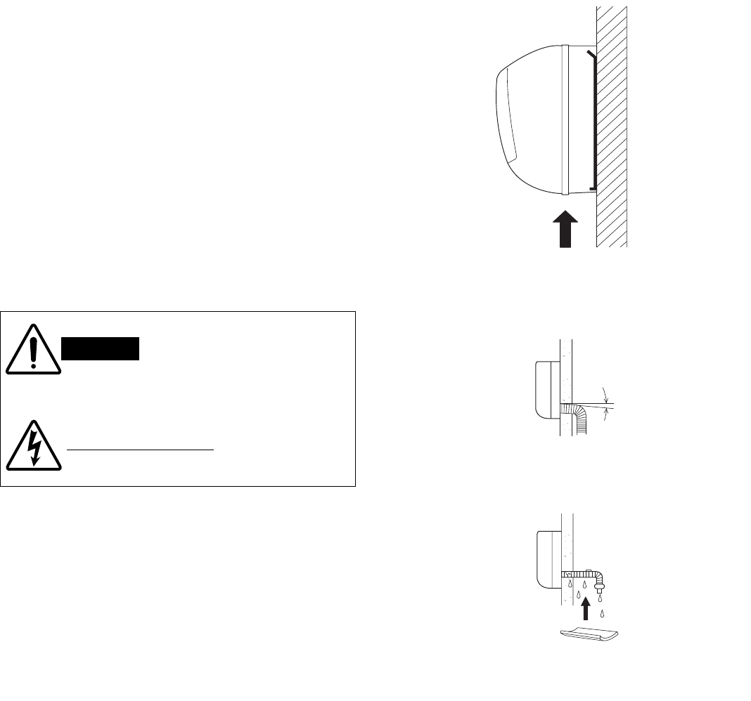
3-10. Drain Hose
a) The drain hose should be slanted downward to the
outdoors. (Fig. 43)
b) Never form a trap in the course of the hose.
c) If the drain hose will run in the room, insulate the
hose with insulation*so that chilled condensation
will not damage furniture or floors. (Fig. 44)
*Foamed polyethylene or its equivalent is recom-
mended.
WARNING
Risk of Electric Shock
Do not supply power to the
unit or operate it until all
tubing and wiring to the out-
side unit are completed.
Condensation
Insulation material
(Locally purchased)
must be used.
Fig. 44
Push
Fig. 42
Slant
Drain
hose
Indoor
unit
Fig. 43
05-326 AirCon_85264189988000 12/5/05 3:35 PM Page 16
17
4. How to Install the Outdoor Unit
First refer to Section 2. Installation Site Selection.
4-1. Wiring Instructions for the Outdoor Unit
Regulations on wire size differ from locality to locality. For
field wiring requirements, please refer to your local elec-
trical codes. Make sure that the installation fully complies
with all local and national regulations.
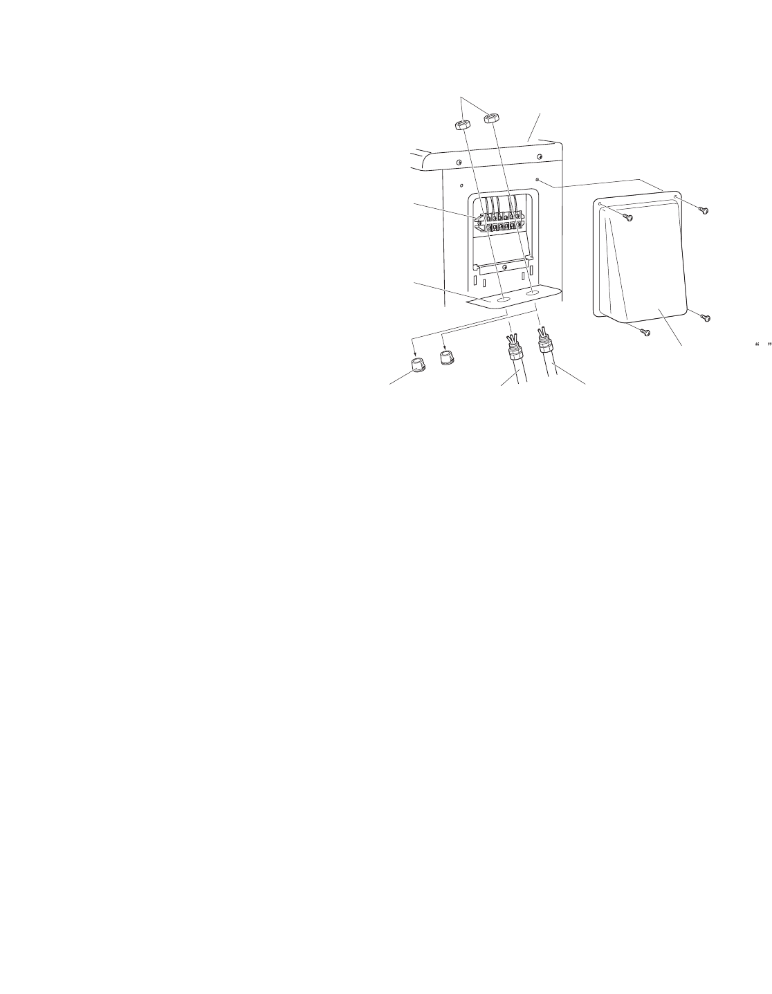
(1) Remove access panel “C”. (Fig. 46)
(2) Connect the inter-unit and power supply line accord-
ing to the drawing on the panel side.
(3) Be sure to size each wire allowing approx. 4"
(10 cm) longer than the required length for wiring.
Store excess wiring inside the cabinet.
(4) When connections are completed, check that all
connections are correct as shown in the wiring sys-
tem diagram on panel side.
(5) Be sure to ground the unit according to your local
codes.
Lock nut
Conduit
plate
Plug Inter unit
(Conduit)
Power supply
(Conduit)
Cabinet
Terminal
block
Access panel C
Fig. 46
05-326 AirCon_85264189988000 12/5/05 3:35 PM Page 17
18
5. Refrigerant Tubing
5-1. Use of the Flaring Method
Many of the conventional split system air conditioners
employ the flaring method to connect refrigerant tubes
which run between indoor and outdoor units. In this
method, the copper tubes are flared at each end and
connected with flare nuts.
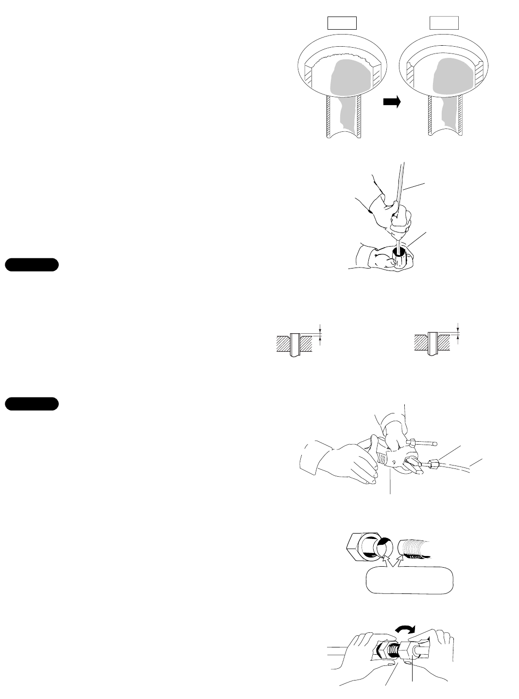
5-2. Flaring Procedure with a Flare Tool
(1) Cut the copper tube to the required length with a
tube cutter. It is recommended to cut approx. 12" to
20" (30 to 50 cm) longer than the tubing length you
estimate.
(2) Remove burrs at the end of the copper tube with a
tube reamer or file. This process is important and
should be done carefully to make a good flare.
(Fig. 47)
When reaming, hold the tube end downward and be
sure that no copper scraps fall into the tube. (Fig. 48)
(3) Remove the flare nut from the unit and be sure to
mount it on the copper tube.
(4) Make a flare at the end of copper tube with a flare
tool.*(Figs. 49a and 49b)
(*Use “RIGID” or equivalent.)
A good flare should have the following characteristics:
Ginside surface is glossy and smooth.
Gedge is smooth.
Gtapered sides are of uniform length.
5-3. Caution before Connecting Tubes Tightly
a) Be sure to apply a sealing cap or water-proof tape
to prevent dust or water from getting into the tubes
before they are used.
b) Be sure to apply refrigerant lubricant to the match-
ing surfaces of the flare and union before connect-
ing them together. This is effective for reducing gas
leaks. (Fig. 50)
c) For proper connection, align the union tube and
flare tube straight with each other, then screw in the
flare nut lightly at first to obtain a smooth match.
(Fig. 51)
NOTE
NOTE
Deburring
Before After
Fig. 47
Reamer
Copper
tubing
Fig. 48
Flare tool
Flare nut
Copper
tubing
Fig. 49b
Fig. 49a
Apply refrigerant
lubricant here and here
Fig. 50
Flare nut
Union
Fig. 51
0 to 0.0196"
(0 to 0.5 mm)
If the special R410A
flare tool is used:
0.0472" (1.2 mm)
If the previous flare tool
(clutch-type) is used:
Adjust so that the amount of tube
protrusion is as shown in the figure.
05-326 AirCon_85264189988000 12/5/05 3:35 PM Page 18
19
5-4. Connecting Tubing between Indoor and
Outdoor Units
a) Tightly connect the indoor side refrigerant tubing exten-
ded from the wall with the outdoor side tubing. (Fig. 52)
b) To fasten the flare nuts, apply specified torque as:
Table 6
5-5. Insulation of Refrigerant Tubing
To prevent heat loss and wet floors due to dripping of con-
densation, both tubes must be well insulated with a
proper insulation material. (Fig. 53)
The thickness of the insulation should be a minimum 5/16"
(8 mm). (Fig. 54)
5-6. Taping the Tubes
(1) At this time, the 2 refrigerant tubes (and electrical wire
if local codes permit) should be taped together with
armoring tape. The drain hose may also be included
and taped together as 1 bundle with the tubing.
(2) Wrap the armoring tape from the bottom of the outdoor
unit to the top of the tubing where it enters the wall. As
you wrap the tubing, overlap half of each previous tape
turn. (Fig. 55)
(3) Clamp the tubing bundle to wall, using 1 clamp approx.
every 47" (120 cm).
Do not wind the armoring tape too tightly, since this will
decrease the heat insulation effect. Also, be sure the con-
densation drain hose splits away from the bundle and drips
clear of the unit and the tubing.
5-7. Finishing the Installation
After finishing insulating and taping over the tubing, use
sealing putty to seal off the hole in the wall to prevent rain
and draft from entering. (Fig. 56)
NOTE
IMPORTANT
Indoor unit
Outdoor unit
Spanner
Torque wrench
Fig. 52
Insulation
Min.
5/16"
(8 mm)
Thickness:
min. 5/16"
(8 mm)
Fig. 54
Fig. 55
Clamp
Insulated tubes
Apply putty here
Tubing
Fig. 56
CAUTION After a tube has been insulat-
ed, never try to bend it into a
narrow curve, as this may
cause the tube to break or
crack.
Insulation
Fig. 53
Tube Dia. Tightening Torque
1/4" (6.35 mm) Approx. 120 – 160 lbs·in (140 – 180 kgf·cm)
3/8" (9.52 mm) Approx. 300 – 360 lbs·in (340 – 420 kgf·cm)
1/2" (12.70 mm) Approx. 430 – 540 lbs·in (490 – 610 kgf·cm)
5/8" (15.88 mm) Approx. 590 – 710 lbs·in (680 – 820 kgf·cm)
05-326 AirCon_85264189988000 12/5/05 3:35 PM Page 19
20
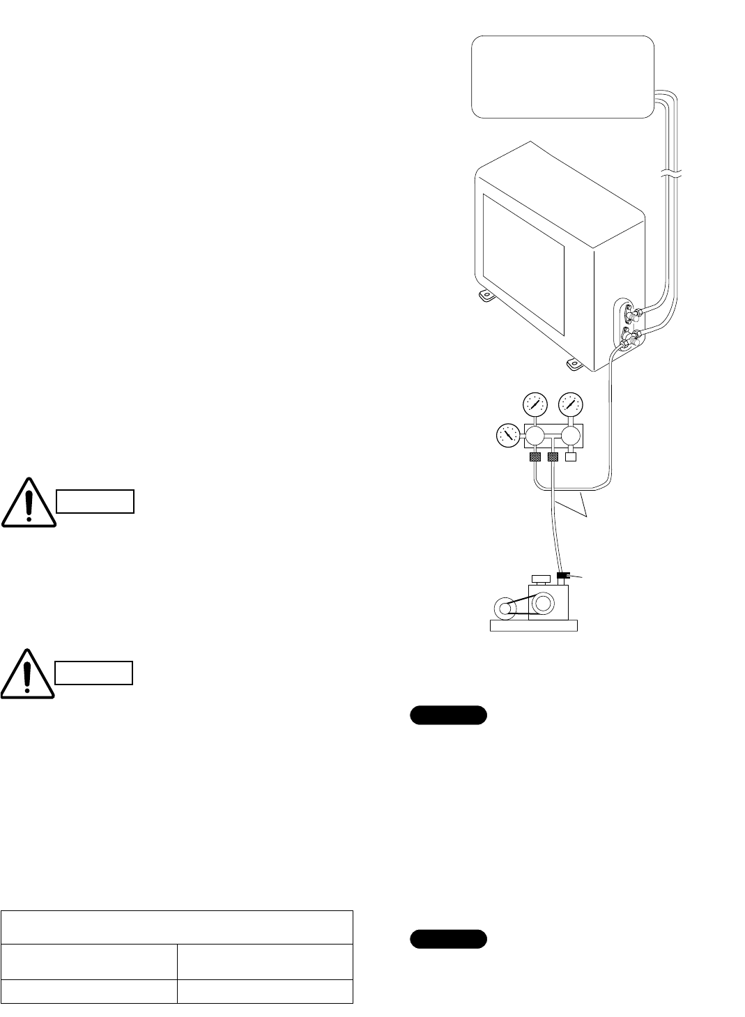
6. Air Purging
Air and moisture remaining in the refrigerant system
have undesirable effects as indicated below. Therefore,
they must be purged completely.
Gpressure in the system rises
Goperating current rises
Gcooling (or heating) efficiency drops
Gmoisture in the air may freeze and block capillary tubing
Gwater may lead to corrosion of parts in the refrigerant
system
IAir Purging with a Vacuum Pump (for Test Run)
(1) Check that each tube (both narrow and wide tubes)
between the indoor and outdoor units have been
properly connected and all wiring for the test run
has been completed. Note that both narrow and
wide tube service valves on the outdoor unit are
kept closed at this stage.
(2) Using an adjustable wrench or box wrench, remove
the valve caps from the service valve on both nar-
row and wide tubes.
(3) Connect a vacuum pump and a manifold valve (with
pressure gauges) to the service port on the wide
tube service valve. (Fig. 57)
(4) With the “Lo” knob of the manifold valve open, run
the vacuum pump. The operation time for the vacu-
um pump varies with tubing length and the capacity
of the pump. The following table shows the amount
of time for evacuation:
Table 7
HiLo
Indoor unit
Outdoor unit
Manifold valve
(Exclusively for R410A)
Pressure
gauge
Vacuum pump
Charging hose
(Exclusively for R410A)
Vacuum pump adapter
(Exclusively for R410A)
(with reverse flow prevention)
Fig. 57
CAUTION Be sure to use a manifold valve
for air purging. If it is not avail-
able, use a stop valve (field sup-
ply) for this purpose. The “Hi”
knob of the manifold valve must
always be kept closed.
The required time in Table 7 is calculated based on the
assumption that the ideal (or target) vacuum condition
is around 10 mmHg abs.
NOTE
Required time for evacuation when
100 liter/h vacuum pump is used
If tubing length is If tubing length is
less than 33 ft. (10 m) more than 33 ft. (10 m)
10 min. or more 15 min. or more
CAUTION
The service port on the wide tube
service valve uses a Schrader core
valve to access the refrigerant sys-
tem. The valve core is similar to
those used in automobile tires.
Therefore, be sure to use a vacuum
hose connector which has a push-
pin inside.
To prevent other refrigerants from being mistakenly
charged to units which use R410A, the size of the
charge port on the service valve is different from the
one for other refrigerant types. For servicing such as
recharging, the specified charging hose, manifold and
vacuum pump adapter (with reverse flow prevention)
for R410A must be used.
NOTE
05-326 AirCon_85264189988000 12/5/05 3:35 PM Page 20
21
(5) With the vacuum pump still running, close the “Lo”
knob of the manifold valve. Then stop the vacuum
pump.
(6) With the accessory hex wrench, turn the valve stem
on the narrow tube service valve counter-clockwise
by 90 degrees (1/4 turn) for 10 seconds, and then
turn the stem clockwise to close it again. (Fig. 58)
(7) Leak test all joints at the tubing (both indoor and out-
doors) with soapy water. Bubbles indicate a leak. Tight-
en the joint more when leaks, then check if there is no
leak. Be sure to wipe off the soap with a clean cloth.
(8) With the hex wrench, turn the wide tube service
valve stem counter-clockwise to fully open the valve.
(9) Turn the narrow tube service valve stem counter-
clockwise to fully open the valve.
(10) Loosen the vacuum hose connected to the wide
tube service port slightly to release the pressure.
Then, remove the hose.
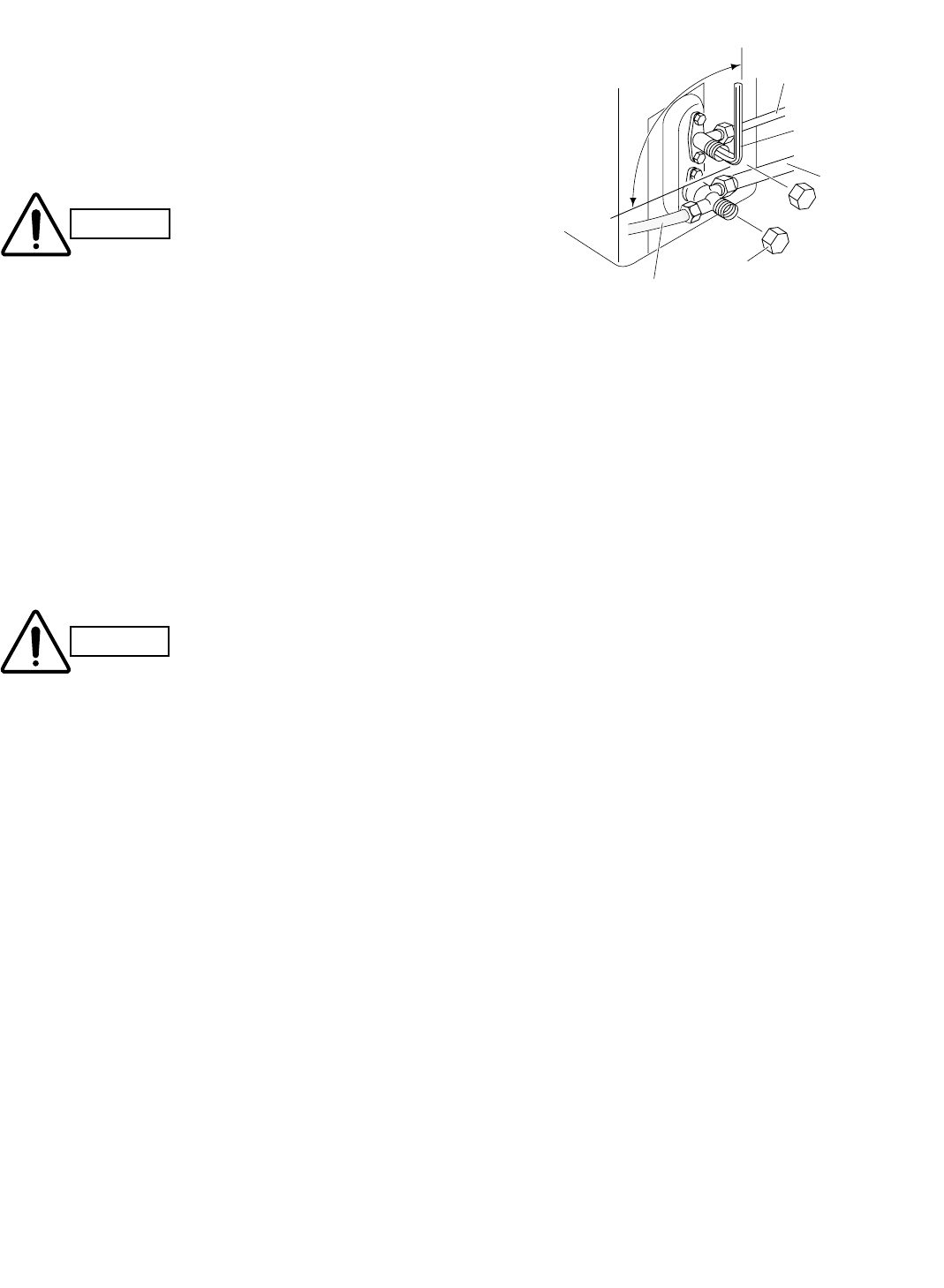
(11) Fasten the valve cap on the wide tube service port
securely with an adjustable wrench or box wrench.
Next, mount the valve cap on the service valve and
tighten it to 170 lbs·in (200 kgf·cm) with a torque
wrench. This process is very important to prevent
gas from leaking from the system.
(12) Test run the air conditioner. (See next page.)
(13) While the air conditioner is running, apply liquid
soap to check for any gas leaks around the service
valves or caps.
(14) If there is no leakage, stop the air conditioner.
(15) Wipe off the soap on the tubing.
This completes air purging with a vacuum pump and the
air conditioner is ready for actual operation.
CAUTION Be sure to completely insert
the hex wrench before
attempting to turn the valve.
Fig. 58
CAUTION This may cause the refriger-
ant gas to leak. In order to
avoid this, take off the hose
quickly.
90° (1/4 turn) Narrow tube
Hex wrench
Wide tube
Valve cap
Vacuum hose to manifold valve
05-326 AirCon_85264189988000 12/5/05 3:35 PM Page 21
22
How to Test Run the Air Conditioner
After turning on power to the air conditioner, use the remote
controller and follow the steps below to conduct the test run.
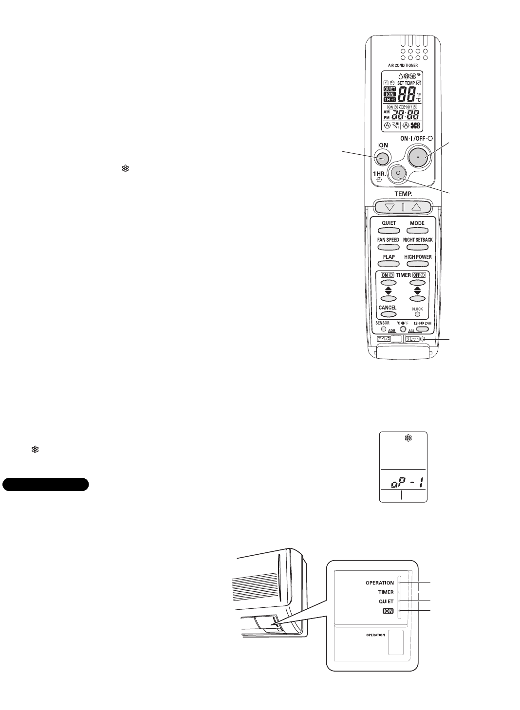
(1) Set the remote controller in Test Run mode.
(Fig. 59a)
a) Press and hold the ION button.
b) Then press and hold the 1HR TIMER button.
c) At the same time, press the ACL (reset) button once.
Use a pointed object such as the tip of a pen to press
the ACL button.
• After a few seconds, “ ” appears and “oP-1” blinks in
the remote controller display area.
(Fig. 59b)
d) Release the 1HR TIMER button.
e) Release the ION button.
(2) Start Cooling mode test run by pressing the ON/OFF
operation button of the remote controller. (Fig. 59a)
• This starts the fan producing uncooled forced air with
the 4 indicator lamps (OPERATION lamp, TIMER
lamp, QUIET lamp, and ION lamp) on the main unit
blinking. (Fig. 59c)
• After 3 minutes, the system shifts into cooling opera-
tion, and cool air will start to be felt. Cool mode test
run is unaffected by the room temperature.
(3) Press the ON/OFF operation button of the remote con-
troller again to stop the test run. (Fig. 59a)
(4) Finally press the ACL (reset) button of the remote con-
troller to release it from Test Run mode to return to nor-
mal mode. (Fig. 59a)
• “ ” and “oP-1” will disappear from the remote con-
troller display area.
After the test run is completed, be sure to press the ACL
(reset) button to return to normal mode. The air conditioner
will not operate correctly if this is not done.
IMPORTANT
Fig. 59a
Fig. 59b
Fig. 59c
A
1HR.
TIMER
ON/OFF
operation
ACL
(Reset)
ION
button
button
button
button
OPERATION lamp
TIMER lamp
QUIET lamp
ION lamp
05-326 AirCon_85264189988000 12/5/05 3:35 PM Page 22
23
IPump Down
Pump down means collecting all refrigerant gas in the
system back into the outdoor unit without losing any of
the gas. Pump down is used when the unit is to be
moved or before servicing the refrigerant circuit.
Pump Down Procedure
Be sure to carry out pump down with the unit in
cooling mode.
(1) Connect the Lo side charging hose of the manifold
valve to the service port on the wide tube service
valve.
(2) Using a hex wrench, turn the narrow tube service
valve clockwise all the way to close the service
valve. (Be sure to confirm that the wide tube service
valve is fully open.)
(3) Press the operation button and start cooling oper-
ation.
(4) When the low pressure gauge reading falls to 14.2 to
7.1 psi (1 to 0.5 kg/cm2), fully close the wide tube
valve stem. Then quickly stop the unit.
(5) Disconnect all gauges and hoses, and replace the
valve caps as they were before.
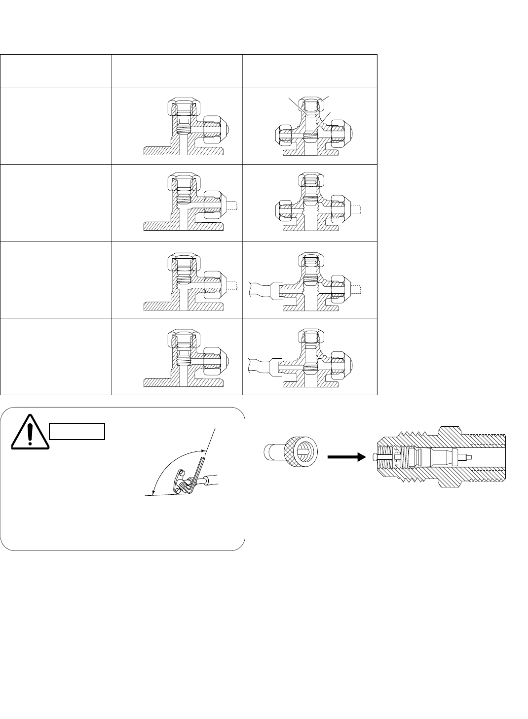
IBasic Functions of the Service Valves
The basic functions of the service valves are given in Table 8 below.
Action Narrow Tube Service
Valve (2-Way)
Wide Tube Service
Valve (3-Way)
CLOSED
Fully OPEN
Fully OPEN
Shipping
Operating and
test running
the air conditioner
Measuring pressure
and gas charging
Air purging with
a vacuum pump
CLOSED
Valve cap
Stem
O-ring
*
*
Table 8
*The service port on the wide tube ser-
vice valve uses a Schrader core valve
to access the refrigerant system.
Therefore, be sure to use a hose con-
nector which has a push-pin inside.
(Fig. 60a)
PUSH
Hose with push-pin
Service valve
Fig. 60a
Close
Hex
wrench
Open
Fig. 60b
CAUTION
When opening or clos-
ing the service valve
stem, use the accessory
hex wrench. Be sure to
fully seat the wrench
before turning the valve.
05-326 AirCon_85264189988000 12/5/05 3:35 PM Page 23
24
7. Remote Control Unit Installation Position
The remote control unit can be operated from either a
non-fixed position or a wall-mounted position.
To ensure that the air conditioner operates correctly, do
not install the remote control unit in the following places:
GIn direct sunlight
GBehind a curtain or other place where it is covered
GMore than 26' (8 m) away from the air conditioner
GIn the path of the air conditioner’s airstream
GWhere it may become extremely hot or cold
GWhere it may be subject to electrical or magnetic
interference
GWhere there is an obstacle between the remote con-
trol unit and the air conditioner (since a check signal
is sent from the remote control unit every 5 minutes)
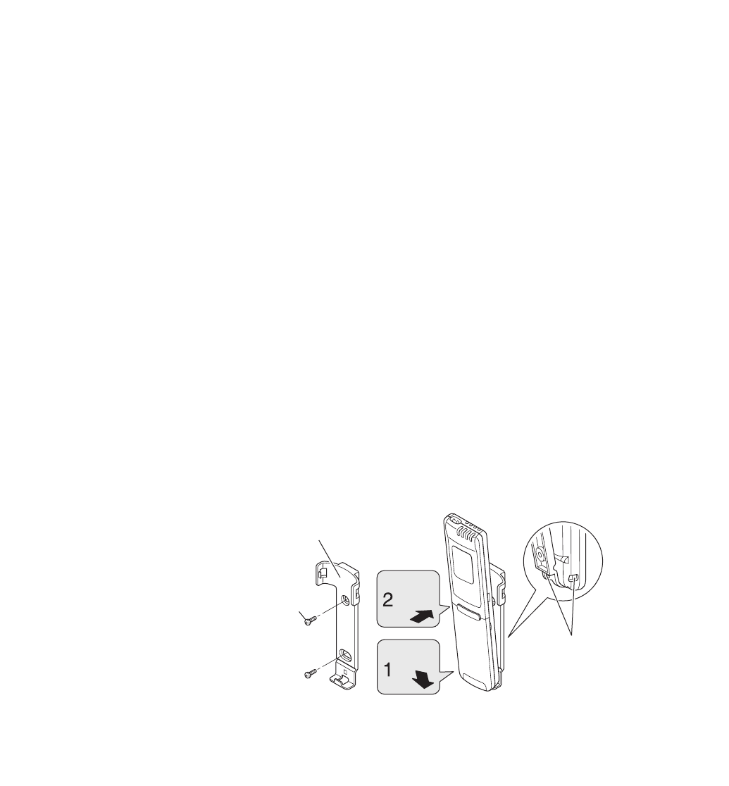
7-1. Mounting on a Wall
Before mounting the remote control unit, press the
ON/OFF operation button at the mounting location to
make sure that the air conditioner operates from that
location. The indoor unit should make a beeping sound
to indicate that it has received the signal.
Hole
Remote control unit mount
Mounting screws
5/32 × 5/8" (4 × 16 mm)
(Included)
Rear side
Press
Set in
place To prevent loss of the remote control
unit, you can connect the remote
control unit to the mount by passing
a string through the remote control
unit and attachment hole.
Fig. 61
To take out the remote control unit, pull it forward.
05-326 AirCon_85264189988000 12/5/05 3:35 PM Page 24
25
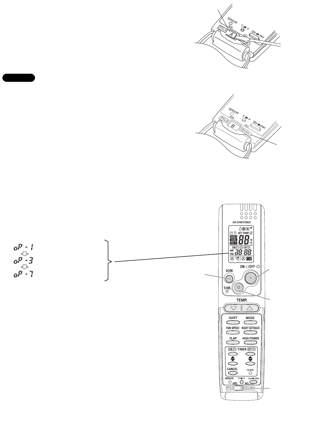
8. Address Switch
8-1. Address Setting of the Remote Control Unit
The address can be set in order to prevent interference
between remote controllers when two Sanyo indoor units
are installed near each other. The address is normally
set to “A.” To set a different address, it is necessary to
change the address on the second remote controller.
Once changed, you cannot restore the original address
setting of the air conditioner.
(1) Switch on the power source.
(2) Break the address-setting tab marked “A” on the
second remote controller to change the address
(Fig. 62). When the tab is removed, the address is
automatically set to B (Fig. 63).
(3) Press and hold the remote controller ION button and
1 HR TIMER button. At the same time, press the
ACL(reset) button. Use a thin object such as the tip
of a pen to press the ACL button. When this has
been done, “oP-1” (test run) appears, blinking, in the
remote controller clock display area.
(4) Each time the 1 HR TIMER button is pressed, the
display changes as shown below. Press this button
2 times to change the display to “oP-7” (address
setting). (Fig. 64)
(5) “oP-7” has now been selected for address setting.
(6) Press the ON/OFF operation button on the remote
controller. (Fig. 64) Check that the “beep”signal-
received sound is heard from the second indoor unit
(approximately 5 times). The sound you hear is the
signal that the remote controller address has been
changed.
(7) Finally press the remote controller ACL (reset) but-
ton to cancel the blinking “oP-7” display.
(Fig. 64)
Changing of the second remote controller address is
now completed.
Test run mode
Selfdiagnostic mode
Address setting mode
NOTE
Fig. 62
Fig. 63
Fig. 64
Tab
ACL button
A
1HR.
TIMER
ON/OFF
operation
ACL
(Reset)
ION
button
button
button
button
05-326 AirCon_85264189988000 12/5/05 3:35 PM Page 25
