Sanyo Stb0810C1 Users Manual
STB1020C1 to the manual 7d29215c-90e3-449e-9284-519af047db1a
2015-01-26
: Sanyo Sanyo-Stb0810C1-Users-Manual-336986 sanyo-stb0810c1-users-manual-336986 sanyo pdf
Open the PDF directly: View PDF ![]() .
.
Page Count: 52
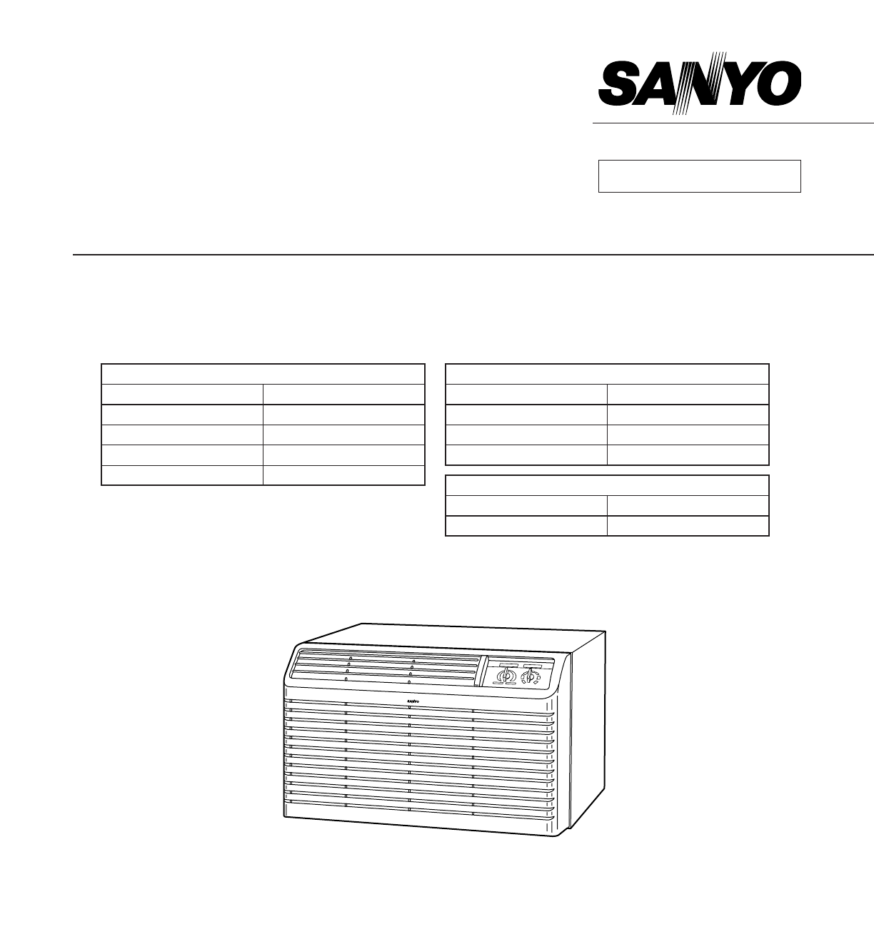
TECHNICAL & SERVICE MANUAL
STB0810C1 STB0811C1
STB1010C1 STB1023C1
STB1020C1 STB1123C1
STB1220C1 STB0823H1
REFERENCE NO. SM700487
SANYO 26˝ THROUGH THE WALL
AIR CONDITIONERS & HEAT PUMP
FILE NO.
STB0810C1 STB0811C1
STB1010C1 STB1023C1
STB1020C1 STB1123C1
STB1220C1 STB0823H1
Destination: U.S.A.
Model No. Product Code No.
STB0810C1–S 1 851 005 66
STB1010C1–S 1 851 005 65
STB1020C1–S 1 851 005 68
STB1220C1–S 1 851 005 67
Model No. Product Code No.
STB0811C1–S 1 851 005 69
STB1023C1–S 1 851 005 51
STB1123C1–S 1 851 005 70
COOLING ONLY MODEL COOLING & ELECTRIC HEATING MODEL
HEAT PUMP MODEL
Model No. Product Code No.
STB0823H1–S 1 851 005 52
IMPORTANT!
Please Read Before Starting
This air conditioner meets strict safety and operating
standards. As the installer or service person, it is an
important part of your job to install or service the system so it
operates safely and efficiently.
For safe installation and trouble-free operation, you
must:
• Carefully read the INSTRUCTION MANUAL and
INSTALLATION INSTRUCTIONS attached to each air
conditioner before beginning.
• Follow each installation or repair step exactly as shown.
• Observe all local, state, and national electrical codes.
• Pay close attention to all warning and caution notices given
in this manual.
This symbol refers to a hazard or unsafe practice which can
result in severe personal injury or death.
This symbol refers to a hazard or unsafe practice which can
result in personal injury or product or property damage.
If Necessary, Get Help
These instructions are all you need for most installation sites
and maintenance conditions. If you require help for a special
problem, contact our sales/service outlet or your certified
dealer for additional instructions.
SPECIAL PRECAUTIONS
When Wiring
ELECTRICAL SHOCK CAN CAUSE SEVERE PERSONAL
INJURY OR DEATH. ONLY A QUALIFIED, EXPERIENCED
ELECTRICIAN SHOULD ATTEMPT TO WIRE THIS
SYSTEM.
• All wiring must conform to local electrical codes.
• Each unit must be properly grounded with a ground (or
earth) wire or through the supply wiring.
• DO NOT, under any circumstances, cut or remove the third
(ground) prong from the power cord plug.
• DO NOT use an adapter Plug or extension cord.
• DO NOT use a damaged power cord, plug, or wall outlet.
Replace them immediately.
• DO NOT change the internal wiring or any part of the
system.
• DO NOT turn the air conditioner on and off by plugging and
unplugging. Use the Operation switch.
When Transporting
Be careful when picking up and moving the air conditioner.
Get a partner to help, and bend your knees when lifting to
reduce strain on your back. Sharp edges or thin aluminum
fins on the air conditioner can cut your fingers.
When Installing
Place of Installation
• If possible, install the unit in a shady location.
• Install it at a spot where optimum air circulation can be
obtained. No chairs or other obstructions are allowed in
front of the air conditioner.
• Keep enough space from any outside obstruction (wall,
bush, etc.).
• As a safety measure, it is recommended that two people
install the unit.
• Hold the unit securely, and be careful not to drop any parts
if the air conditioner is being installed on an upper floor of a
multistory building.
When Servicing
• Turn the power OFF at the main power box (mains) before
opening the unit to check or repair electrical parts and
wiring.
• Keep fingers and clothing away from any moving parts.
• Clean up the site after you finish, remembering to check
that no metal scraps or bits of tools have been left inside
the unit being serviced.
Others
• Ventilate any enclosed areas when installing or testing the
refrigeration system. Escaped refrigerant gas, on contact
with fire or heat, can produce dangerously toxic gas.
• Confirm upon completing installation that no refrigerant gas
is leaking. If escaped gas comes in contact with a stove,
gas water heater, electric room heater or other heat source,
it can produce dangerously toxic gas.
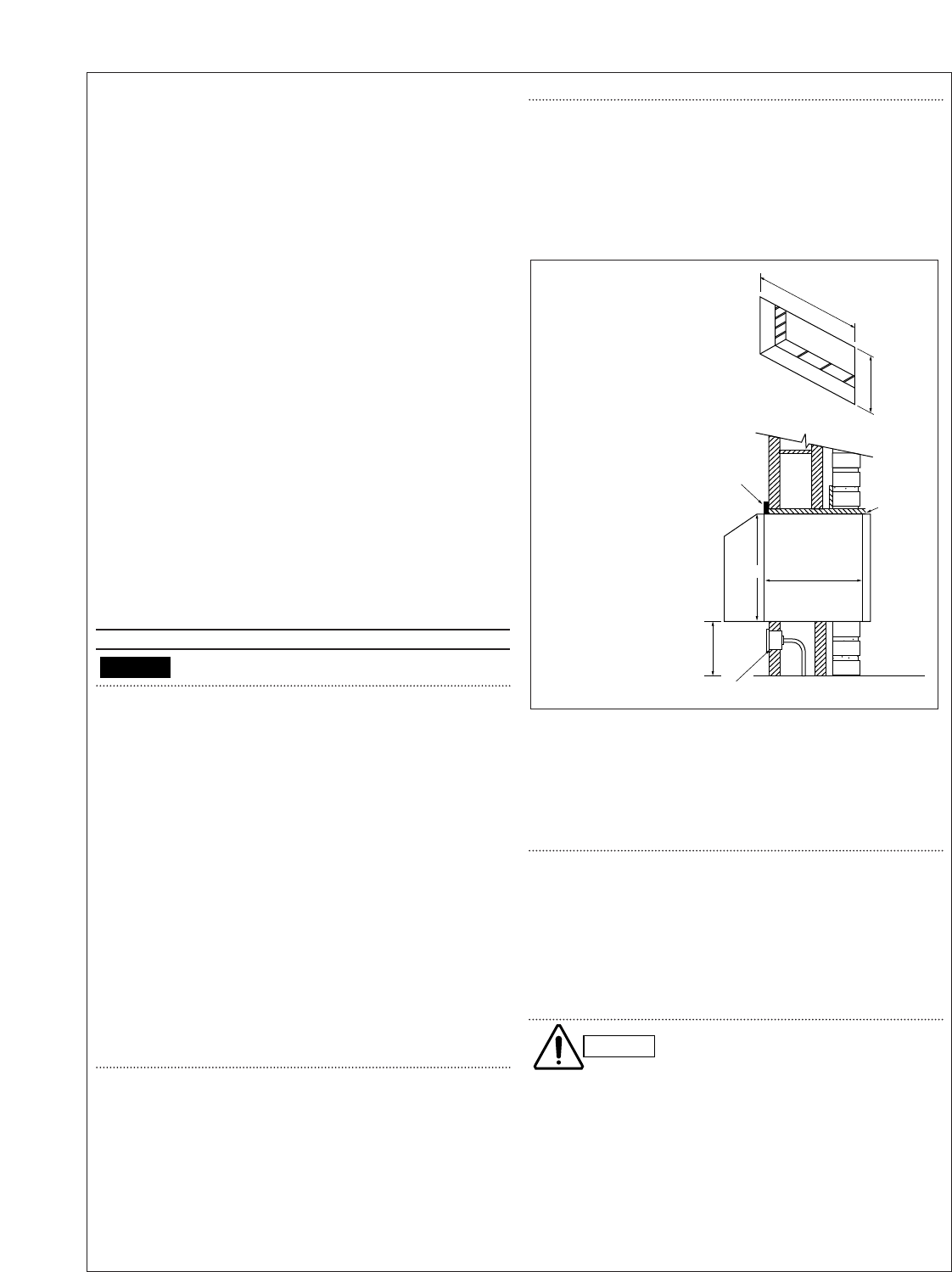
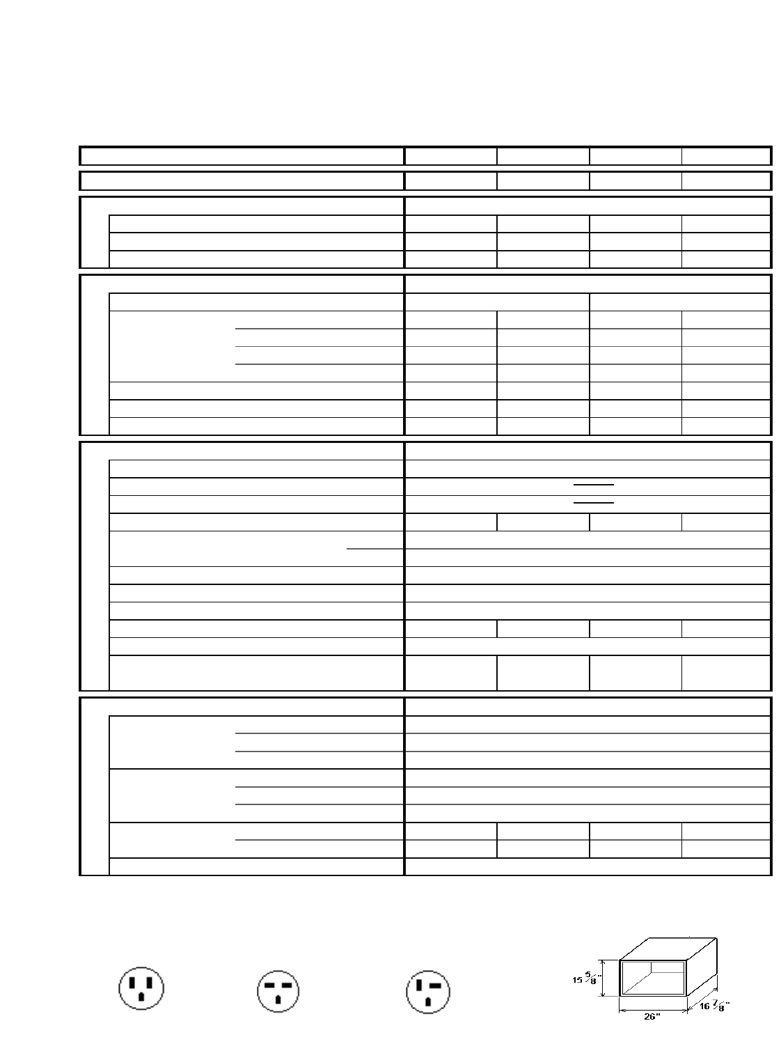
CAUTION
Dimension of
Wall Opening
Wall opening of
26-1/8" x 15-3/4"
is required
Be sure to use lintel
to support the block
and brick above the
sleeve to retain the
weight of the unit
Minimum Wall Sleeve Opening
Trim
molding
(if desired)
Minimum
5" from
the floor
Caulk
(4sides)
OutsideRoom side 16
7
/
8
"
15
3
/
4
26
1
/
8
15
7
/
8
"
Box and receptacle
WARNING
i
ii
HOW TO USE THIS MANUAL
This manual is designed to help service personnel to understand basic functions, operation and possible troubles
and their remedies on SANYO 26˝ Through The Wall Air Conditioner. You can use this manual both as a reference
to find specific information about the capacity, construction of the unit, and as a source of information to help you
set up and maintain the air conditioner. Please use this manual to make your work easier, keep the air conditioner
functioning well, and keep your customer satisfied.
Please read IMPORTANT ! precautional information on the previous page before you start actual work.
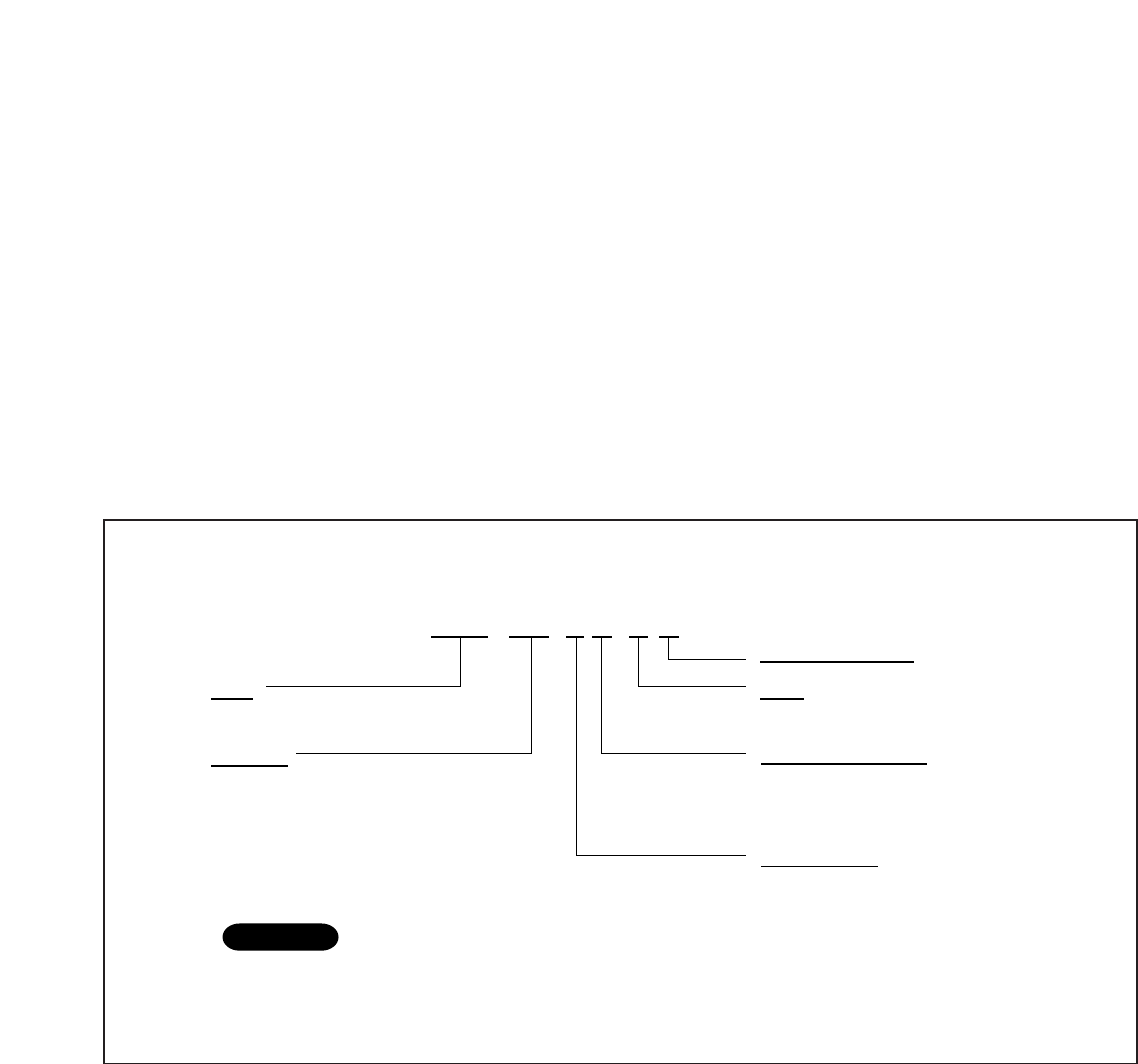
SANYO 26˝ THROUGH THE WALL A/C MODEL IDENTIFICATION
SANYO 26˝ Through The Wall Air Conditioner is identified by a model number. Cooling or heating capacity,
electrical information and special features included on the air conditioner are indicated on the model number.
STB 1 0 2 3 C 1
Type
STB : SANYO 26˝ Thru the wall
Capacity
08 : 8,000 BTU/h class
10 : 10,000 BTU/h class
11 : 11,000 BTU/h class
12 : 12,000 BTU/h class
Electric Heater Size
0 : No Electric Heater
1 : 1.2 kW
3 : 3.4 kW
Power Supply
1 : 60Hz 115 V
2 : 60Hz 230 / 208 V
Type
C : Cooling H : Heat Pump
Development Flag
NOTE
Example
To identify the correct model number of your air conditioner, you must find the nameplate.
The name plate is usually located in front of electric component box (behind the grille).
First, remove the grille to access the electric component box.

iii
Table of Contents Page
1. OPERATING RANGE ............................................................................................................................... 1
2. SPECIFICATIONS
2-1. Unit Specifications.......................................................................................................................... 2
2-2. Major Component Specifications ................................................................................................... 4
2-3. Other Component Specifications.................................................................................................... 6
3. DIMENSIONAL DATA............................................................................................................................... 7
4. REFRIGERANT FLOW DIAGRAM .......................................................................................................... 8
5. PERFORMANCE DATA
5-1. Cooling Capacity ........................................................................................................................... 9
5-2. Heating Capacity ........................................................................................................................... 17
6. ELECTRICAL DATA
6-1. Electrical Characteristics ............................................................................................................... 18
6-2. Electrical Wiring Diagrams ............................................................................................................ 21
6-3. P.C.B. Ass'y (Printed Pattern) ........................................................................................................ 27
7. TROUBLESHOOTING
7-1. Check before and after troubleshooting ........................................................................................ 28
7-2. Air conditioner does not operate .................................................................................................... 29
7-3. Some part of air conditioner does not operate .............................................................................. 31
7-4. Air conditioner operates, but abnormalities are observed ............................................................. 33
7-5. If a sensor is defective ................................................................................................................... 34
8. CHECKING ELECTRICAL COMPONENTS
8-1. Measurement of Insulation Resistance .......................................................................................... 35
8-2. Checking Motor Capacitor.............................................................................................................. 36
8-3. Checking Fan Motor Winding ......................................................................................................... 36
8-4. Checking Compressor Motor Winding............................................................................................ 36
8-5. Checking Thermistor ...................................................................................................................... 36
9. DISASSEMBLY PROCEDURE
9-1. Removing Front Grille..................................................................................................................... 37
9-2. Removing Wall Sleeve ................................................................................................................... 37
9-3. Removing Electrical Component Box............................................................................................. 37
9-4. Removing Electric Heater............................................................................................................... 38
9-5. Removing Blower Wheel ................................................................................................................ 39
9-6. Removing Evaporator..................................................................................................................... 39
9-7. Removing Condenser..................................................................................................................... 40
9-8. Removing Propeller Fan................................................................................................................. 40
9-9. Removing Fan Motor...................................................................................................................... 41
10.FUNCTION
10-1. Room temperature Control ............................................................................................................ 42
10-2. Defrosting Operation (Heating)....................................................................................................... 45
.................................................................................................................................................. 46
APPENDIX
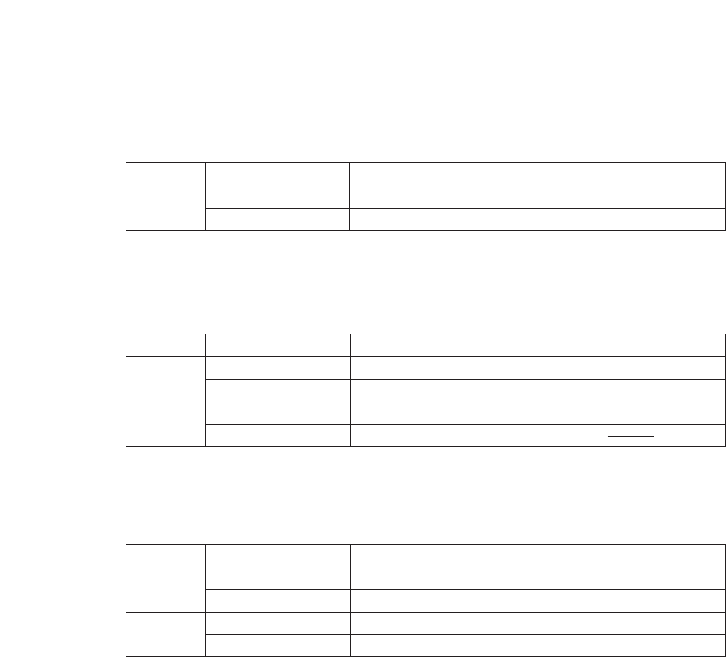
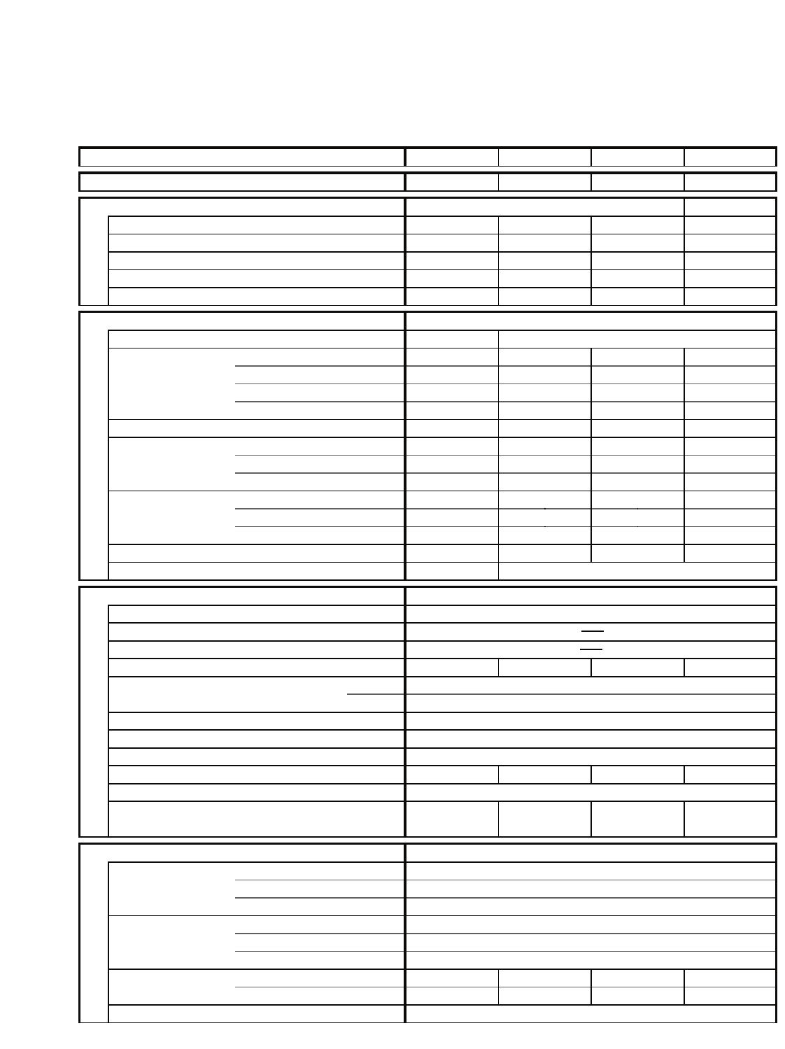
1. OPERATING RANGE
Temperature Indoor Air Intake Temp. Outdoor Air Intake Temp.
Cooling Maximum 95°F D.B. / 71°F W.B. 115°F D.B.
Minimum 67°F D.B. / 57°F W.B. 67°F D.B.
1
Temperature Indoor Air Intake Temp. Outdoor Air Intake Temp.
Cooling Maximum 95°F D.B. / 71°F W.B. 115°F D.B.
Minimum 67°F D.B. / 57°F W.B. 67°F D.B.
Heating Maximum 80°F D.B. / 67°F W.B.
Minimum — D.B. / — W.B.
■COOLING ONLY MODEL
Models STB0810C1 STB1010C1 STB1020C1 STB1220C1
■HEAT PUMP MODEL
Model STB0823H1
Temperature Indoor Air Intake Temp. Outdoor Air Intake Temp.
Cooling Maximum 95°F D.B. / 71°F W.B. 115°F D.B.
Minimum 67°F D.B. / 57°F W.B. 67°F D.B.
Heating Maximum 80°F D.B. / 67°F W.B. 75°F D.B. / 65°F W.B.
Minimum — D.B. / — W.B. 17°F D.B. / 15°F W.B.
■COOLING & ELECTRIC HEATING MODEL
Models STB0811C1 STB1023C1 STB1123C1
2
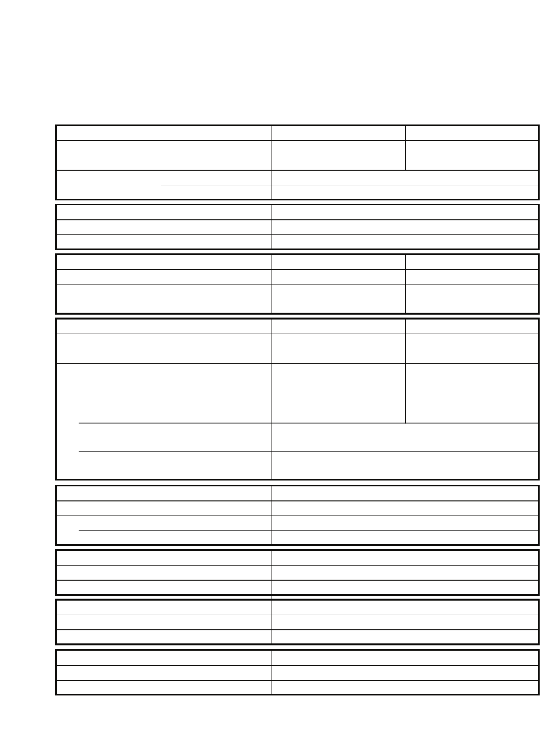
2. SPECIFICATIONS
2-1. Unit Specifications
Model Number STB0810C1 STB1010C1 STB1020C1 STB1220C1
Voltage (V) 115 115 230 / 208 230 / 208
Performance COOLING
Cooling Capacity BTU/h 8,200 10,200 9,700 / 9,500
11,500 / 11,300
Air Flow....Hi CFM (CMM) 270 (7.65) 270 (7.65) 270 (7.65) 270 (7.65)
Dihumidification Pints/h 2.0 2.7 2.6 3.2
Electrical Rating
Available voltage range V 104 ~ 126 253 ~ 187
Cooling Amperes A 8.3 10.6 5.0 / 5.3 6.1 / 6.6
Watts W 940 1,200 1,140 / 1,110 1,350 / 1,330
Power factor % 98 98 99 / 100 96 / 97
EER BTU/hW 8.7 8.5 8.5 / 8.5 8.5 / 8.5
Starting amperes A 43 53 30 34
Recommeded Circuit Protection A 15 15 15 15
Plug Type Parallel Parallel Tandem Tandem
Features
Controls / Temperature control Mechanical / Thermostat
Control unit
Timer
Fan speeds 2 2 2 2
Airflow direction (Indoor) Horizontal Manual
Vertical Manual
Air filter Washable
Air exhaust Yes
Compressor Rotary (Hermetic)
R22-Amount charged at shipment OZ 20.1 28.2 23.3 28.2
Refrigerant control Capillary tube
Operation sound Indoor : Hi / Lo dB-A 57 / 55 60 / 57 60 / 57 60 / 57
Outdoor : Hi / Lo dB-A 63 / 60 68 / 64 68 / 64 68 / 64
Dimensions & Weight
Unit dimensions Height In 15-3/4
(Refer to page 7) Width In 25-15/16
Depth In 21-1/2
Package dimensions Height In 18-5/16
Width In 29-1/8
Depth In 24-11/16
Weight Net lbs 82 90 89 93
Shipping lbs 93 101 100 104
Shipping volume Cuft 7.62
DATA SUBJECT TO CHANGE WITHOUT NOTICE.
Parallele
115V
15AMP
Tandem
230/208V
15AMP
Perpendicular
230/208V
20AMP
Wall Receptacles
Wall Sleeve Dimension
Remarks: Rating conditions are:
Cooling : Indoor air temperature 80°F D.B. / 67°F W.B. Heating : Indoor air temperature 70°F D.B.
Outdoor air temperature 95°F D.B. / 75°F W.B. Outdoor air temperature 47°F D.B. / 43°F W.B.
Models STB0810C1 STB1010C1 STB1020C1 STB1220C1
3
Models STB0811C1 STB1023C1 STB1123C1 STB0823H1
Model Number STB0811C1 STB1023C1 STB1123C1 STB0823H1
Voltage (V) 115 230 / 208 230 / 208 230 / 208
Performance COOLING & ELECTRIC HEATING HEAT PUMP
Cooling Capacity BTU/h 8,000 9,500 / 9,300
11,300 / 11,000
8,000 / 7,800
Heat pump Capacity BTU/h — — — 7,500 / 7,400
Electric Heating Capacity BTU/h 4,040 11,250 / 9,200 11,250 / 9,200 11,250 / 9,200
Air Flow....Hi CFM (CMM) 250 (7.08) 250 (7.08) 250 (7.08) 250 (7.08)
Dihumidification Pints/h 2.0 2.6 3.2 2.0
Electrical Rating
Available voltage range V 104 ~ 126 253 ~ 187
Cooling Amperes A 8.3 5.0 / 5.3 6.0 / 6.5 4.2 / 4.5
Watts W 920 1,120 / 1,090 1,330 / 1,310 940 / 920
Power factor % 96 97 / 99 96 / 97 97 / 98
EER BTU/hW 8.7 8.5 / 8.5 8.5 / 8.5 8.5 / 8.5
Starting amperes A 43 30 34 25
Heat pump Amperes A — — — 4.0 / 4.3
Watts W — — — 880 / 870
COP W / W — — — 2.5 / 2.5
Electric Heater Amperes A 12.0 15.5 / 14.2 15.5 / 14.2 15.5 / 14.2
Watts W 1,350 3,550 / 2,930 3,550 / 2,930 3,550 / 2,930
Element kW 1.22 3.4 3.4 3.4
Recommeded Circuit Protection A 15 20 20 20
Plug Type Parallel Perpendicular
Features
Controls / Temperature control Mechanical / Thermostat
Control unit
Timer
Fan speeds 2 2 2 2
Airflow direction (Indoor) Horizontal Manual
Vertical Manual
Air filter Washable
Air exhaust Yes
Compressor Rotary (Hermetic)
R22-Amount charged at shipment OZ 20.1 23.3 27.2 28.2
Refrigerant control Capillary tube 3
Operation sound Indoor : Hi / Lo dB-A 57 / 55 60 / 56 60 / 56 57 / 55
Outdoor : Hi / Lo dB-A 64 / 61 68 / 62 68 / 62 64 / 61
Dimensions & Weight
Unit dimensions Height In 15-3/4
(Refer to page 7) Width In 25-15/16
Depth In 21-1/2
Package dimensions Height In 18-5/16
Width In 29-1/8
Depth In 24-11/16
Weight Net lbs 82 89 95 90
Shipping lbs 93 100 106 101
Shipping volume Cuft 7.62
DATA SUBJECT TO CHANGE WITHOUT NOTICE.
4
2-2. Major Component Specifications
Models STB0810C1 STB1010C1 STB1020C1 STB1220C1
Model Number STB0810C1 STB1010C1 STB1020C1 STB1220C1
Controller PCB
Part No.
Controls
Control circuit fuse
Compressor
Type Rotary (Hermetic) Rotary (Hermetic) Rotary (Hermetic) Rotary (Hermetic)
Compressor model C-1R62H2D C-R80H2C C-R76H6K C-R95H6C
( Parts code No. ) ( 80663842-S ) ( 80680342-S ) ( 80677946-S ) ( 80695246-S )
Source 115V 1-phase 60Hz 115V 1-phase 60Hz 230-208V 1-phase 60Hz 230-208V 1-phase 60Hz
Nominal output W625 800 750 950
Compressor oil ... Amount cc SUNISO 4GSD-T....350 SUNISO 4GSD-T....350 SUNISO 4GSD-T....350 SUNISO 4GSD-T....450
Coil resistance (at 77°F) ΩC-R: 1.010 C-R: 0.639 C-R: 2.288 C-R: 1.886
C-S: 5.996 C-S: 2.410 C-S: 5.385 C-S: 0.639
Safety device Type External protector External protector External protector External protector
Overload relay MRA98869-9200 MRA98748-9200 MRA98735-9201 MRA99038-9201
Operating temp. Open °F 293±9 302±9 311±9 293±9
Close °F 156±20 156±20 156±20 156±20
Operating amp.(at 77 °F) Trip in 6 to sec.at 30.5A Trip in 6 to 16 sec. at 40A Trip in 6 to 16 sec. at 24A Trip in 6 to 16 sec. at 24A
Run capacitor µF 25 35 20 22.5
VAC 400 400 400 400
Fan & Fan Motor
Fan Type Indoor (Dia. / Depth) In Centrifigal (Dia 7-3/32 : Depth 3-17/32)
Outdoor (Dia. / Depth) In Puropeller (Dia 12-19/32 : Depth 3-3/8)
Fan motor model ... Q'ty KFC6S-91A1P...1 KFC6S-91A6P...1
Source 115V 1-phase 60Hz 230-208V 1-phase 60Hz
No. of poles ... rpm, High (V) 6...1,110(115V) 6...1,080(208V) 1,100(230V)
Nominal output W90 90
Coil resistance (at 68°F) ΩBLU-BLN: 16.59 WHT-BLN: 60.10
BLU-YEL: 7.84 WHT-BLN: 33.46
BLU-PNK: 17.19 WHT-PNK: 59.31
Safety device Type Thermal protector Thermal protector
Operating temp. Open °F 248±9 248±9
Close °F 171±27 171±27
Run capacitor µF 16 4
VAC 220 440
Heat Exch. Coil
Evaporator Coil Aluminum plate fin / Copper tube
Rows 2223
Fins per inch 19.5 19.5 19.5 15.9
Face area
ft21.049 1.049 1.049 1.049
Condenser Coil Aluminum plate fin / Copper tube
Rows 2333
Fins per inch 18.1 14.1 14.1 18.1
Face area
ft21.075 1.075 1.075 1.075
DATA SUBJECT TO CHANGE WITHOUT NOTICE.
5
Models STB0811C1 STB1023C1 STB1123C1 STB0823H1
Model Number STB0811C1 STB1023C1 STB1123C1 STB0823H1
Controller PCB
Part No. 851-0-5171-660-00
Controls POW-STBH
Control circuit fuse
Compressor
Type Rotary (Hermetic) Rotary (Hermetic) Rotary (Hermetic) Rotary (Hermetic)
Compressor model C-1R62H2D C-R76H6K C-R95H6C C-1R65H6W
( Parts code No. ) ( 80663842-s) ( 80677946-S ) ( 80695246-S ) ( 80665146-S )
Source 115V 1-phase 60Hz 230-208V 1-phase 60Hz 230-208V 1-phase 60Hz 230-208V 1-phase 60Hz
Nominal output W625 750 950 650
Compressor oil ... Amount cc SUNISO 4GSD-T....350 SUNISO 4GSD-T....350 SUNISO 4GSD-T....450 SUNISO 4GSD-T....350
Coil resistance (at 77°F) ΩC-R: 1.010 C-R: 2.288 C-R: 1.886 C-R: 3.311
C-S: 5.996 C-S: 5.385 C-S: 0.639 C-S: 3.529
Safety devices
Type External protector External protector External protector External protector
Overload relay MRA98869-9200 MRA98735-9201 MRA99038-9201 MRA99082-9201
Operating temp. Open °F 293±9 311±9 293±9 293±9
Close °F 156±20 156±20 156±20 156±20
Operating amp.(at 77 °F) Trip in 6 to sec.at 30.5A Trip in 6 to 16 sec. at 24A Trip in 6 to 16 sec. at 24A Trip in 6 to 16 sec. at 16.5A
Run capacitor µF 25 20 22.5 22.5
VAC 400 400 400 400
Fan & Fan Motor
Fan Type Indoor (Dia. / Depth) In Centrifigal (Dia 7-3/32 : Depth 3-17/32)
Outdoor (Dia. / Depth) In Puropeller (Dia 12-19/32 : Depth 3-3/8)
Fan motor model ... Q'ty KFC6S-91A1P...1 KFC6S-91A6P...1
Source 115V 1-phase 60Hz 230-208V 1-phase 60Hz
No. of poles ... rpm, High (V) 6...1,110(115V) 6...1,080(208V) 1,100(230V)
Nominal output W90 90
Coil resistance (at 68°F) ΩBLU-BLN: 16.59 WHT-BLN: 60.10
BLU-YEL: 7.84 WHT-BLN: 33.46
BLU-PNK: 17.19 WHT-PNK: 59.31
Safety device Type Thermal protector Thermal protector
Operating temp. Open °F 248±9 248±9
Close °F 171±27 171±27
Run capacitor µF 16 4
VAC 220 440
Heat Exch. Coil
Evaporator Coil Aluminum plate fin / Copper tube
Rows 2 2 3 3
Fins per inch 19.5 19.5 15.9 14.1
Face area
ft21.049 1.049 1.049 1.049
Condenser Coil Aluminum plate fin / Copper tube
Rows 2 3 3 3
Fins per inch 18.1 14.1 18.1 14.1
Face area
ft21.075 1.075 1.075 1.075
DATA SUBJECT TO CHANGE WITHOUT NOTICE.
6
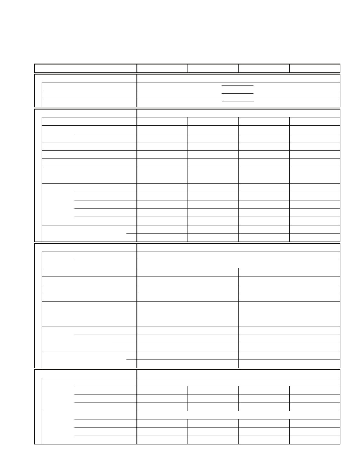
2-3. Other Component Specifications
Models STB0810C1 STB1010C1 STB1020C1 STB1220C1
STB0811C1 STB1023C1 STB1123C1 STB0823H1
Room Thermostat YTB-2U136 YTB-2U358
Model STB1020C1 STB0810C1 STB0811C1 STB1023C1
STB1220C1 STB1010C1 STB1123C1
Openrating temp. Cold °F ON: 65 / OFF: 61±3 (Diff: 4 Deg)
Warm °F ON: 90 / OFF:86
PTC Thermister (for compressor start up) PTH491A04AR470N500
Model STB0810C1 STB0811C1
Resistance at 77°F Ω47±30%
Relay (Heater) VC20A-115-S VC20A-230-S
Model STB0811C1 STB1023C1 STB1123C1
Coil rating AC115V , 60Hz AC208/230V , 60Hz
Contact rating AC265V , 22A AC265V , 22A
Electoric Heater Ass'y AH-H06S AH-H10S
Model STB0811C1 STB1023C1 STB0823H1
STB1123C1
Heater Element Rating 1.22 kW , 115V 3.4 kW , 230V
Resistance Ω 9.5±1.5% (at 68°F) 13.6±1.5% (at 68°F)
Watt Dinsty
w/in28.9 13.2
Dimension In Dia 3/8 , Leng 36 Dia 3/8 , Leng 36
Heater Thermo. Type CS-7L
Openrating temp °F OFF : 122±5 / ON : 95±9
Fuse Type SF-152U
Openrating temp °F 306±5
Power Trnsformer ATR-J64ULN2
Model STB0823H1
Rating Primary AC220V , 60Hz
Secondary AC19V , 0.3A
Thermister (Room sensor) PBC-41E-S29
Model STB0823H1
Resistance at 32°F kΩ15±5%
Thermister (Outdoor coil) PBC-41E-S14
Model STB0823H1
Resistance at 32°F kΩ15±5%
4-way Valve (Solenoid coil) CHV-01AQ503UA1(Coil) / CHV-01U1(Valve)
Model STB0823H1
Coil raiting AC208/230V (60Hz) , 6W
7
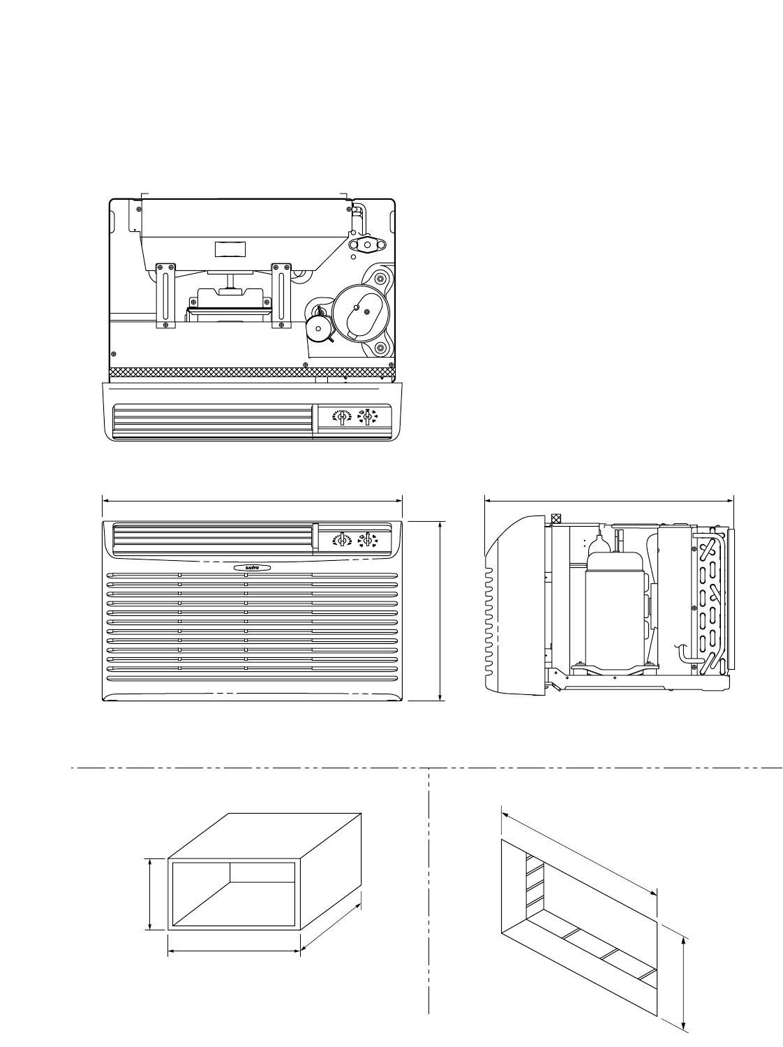
3. DIMENSIONAL DATA
Models STB0810C1 STB1010C1 STB1020C1 STB1220C1
STB0811C1 STB1023C1 STB1123C1 STB0823H1
21 -1/2"
25 -15/16"
15 -3/4"
Front view
Top view
Side view
26 -1/8"
■ Wall Sleeve Dimension
26"
16 -7/8"
15 -3/4"
15 -5/8"
■ Dimension of Wall Opening
■ Unit Dimension
Minimum Wall
Sleeve Opening
Wall opening of
26-1/8˝ x 15-3/4˝
is required
Unit : inch
Unit : inch
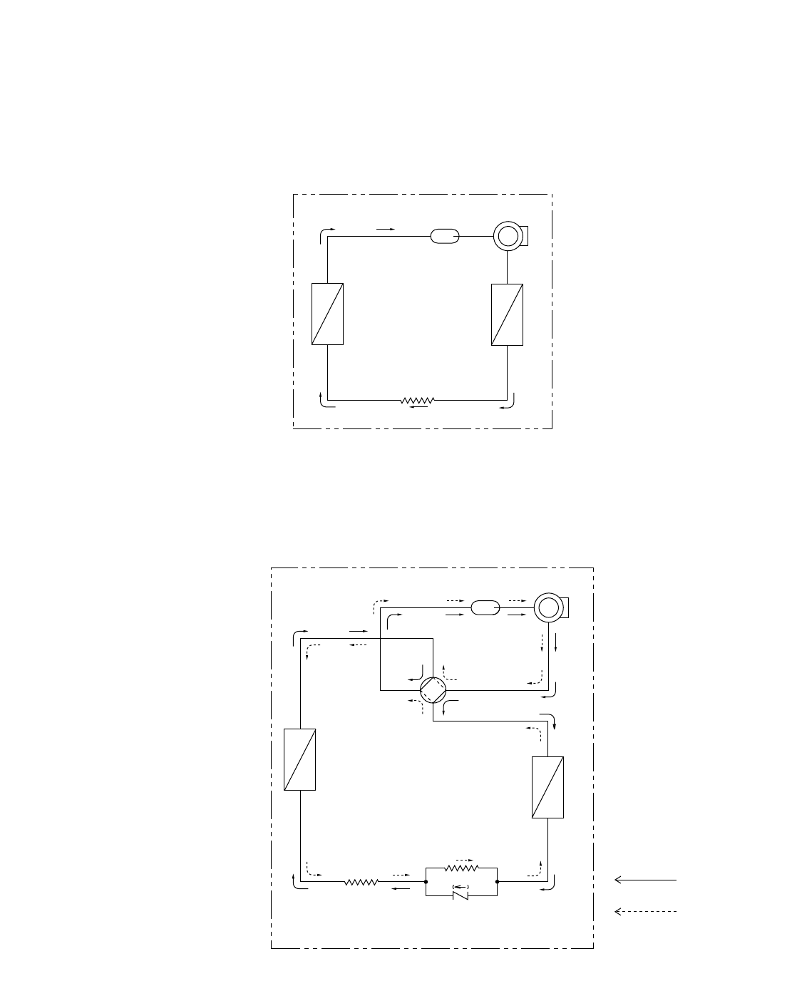
4. REFRIGERANT FLOW DIAGRAM
Compressor
4-way
valve
Accumulator
Outdoor heat
exchanger
Indoor heat
exchanger
Cooling cycle
Heating cycle
Capillary
tube
Capillary
tube
Check
valve
Model STB0823H1
Compressor
Accumulator
Condenser
Evaporator
Capillary
tube
Models STB0810C1 STB1010C1 STB1020C1 STB1220C1
STB0811C1 STB1023C1 STB1123C1
8

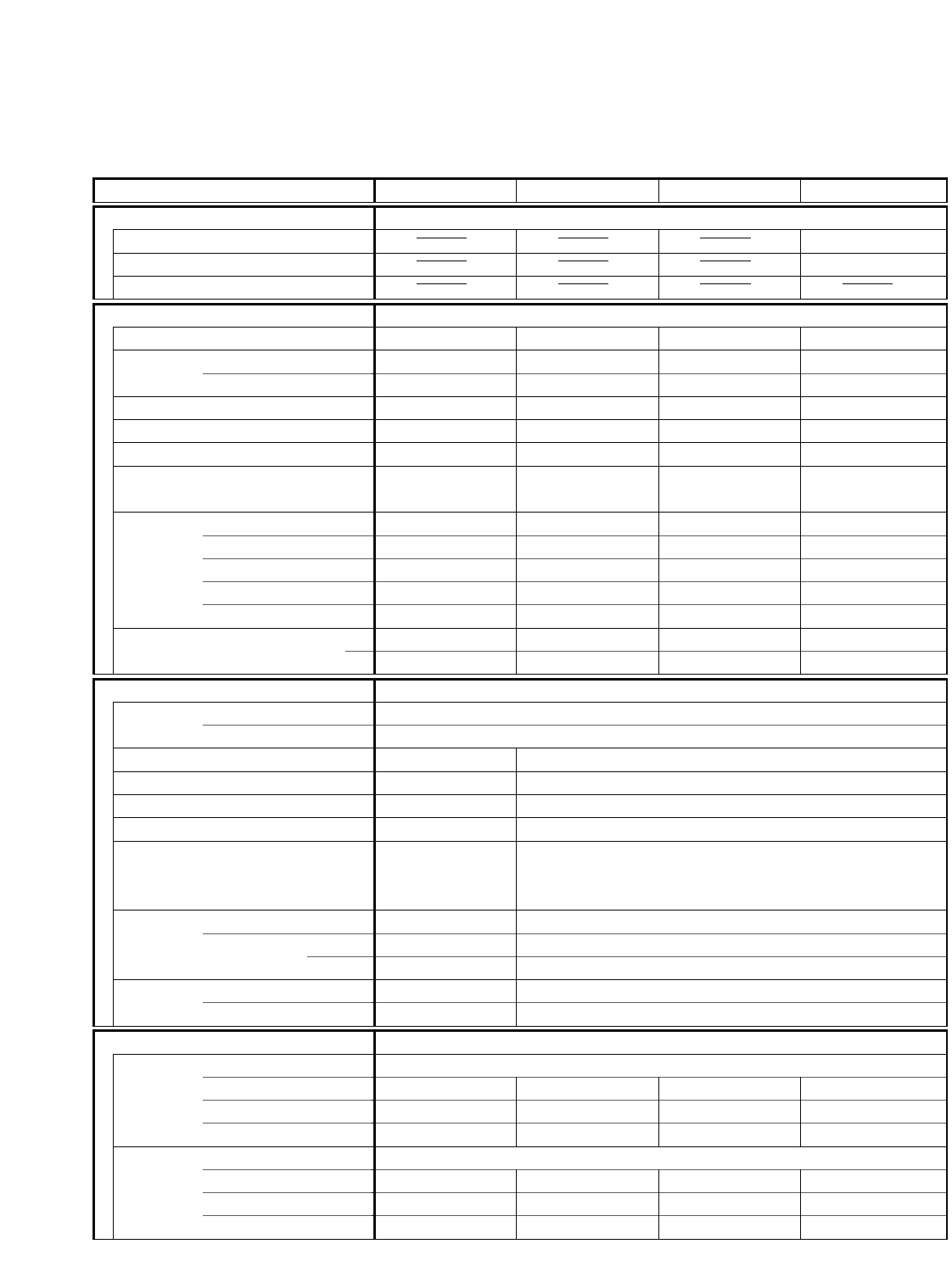
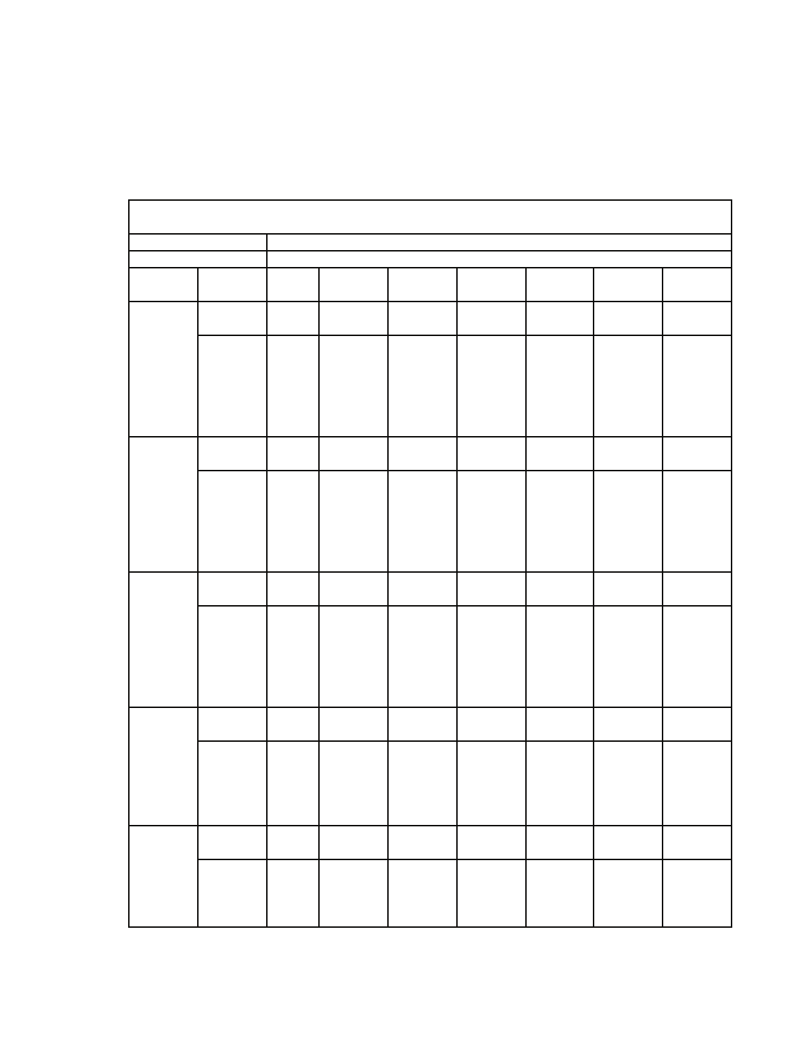
5. PERFORMANCE DATA
5-1. Cooling Capacity
115 V Single phase 60 Hz
RATING CAPACITY 8,200 BTU/h
AIR FLOW RATE 270 CFM
EVAPORATOR CONDENSER
ENT. TEMP. °F (°C) OUTDOOR AMBIENT TEMP. °F( °C)
W.B. D.B. 67 75 85 95 105 110
(19.4) (23.9) (29.4) (35.0) (40.6) (43.3)
TC 8,260 7,900 7,540 7,180 6,750 6,210
CM 0.60 0.65 0.70 0.75 0.79 0.84
70 (21.1) SHC 6,260 6,100 5,940 5,780 5,580 5,350
59 73 (22.8) SHC 7,310 7,150 6,990 6,830 6,630 6,210
(15.0) 77 (25.0) SHC 8,260 7,900 7,540 7,180 6,750 6,210
80 (26.7) SHC 8,260 7,900 7,540 7,180 6,750 6,210
84 (28.9) SHC 8,260 7,900 7,540 7,180 6,750 6,210
88 (31.1) SHC 8,260 7,900 7,540 7,180 6,750 6,210
TC 9,350 8,480 8,090 7,710 7,250 6,670
CM 0.62 0.67 0.72 0.77 0.81 0.86
70 (21.1) SHC 5,170 5,010 4,840 4,680 4,490 4,260
63 73 (22.8) SHC 6,220 6,060 5,890 5,730 5,540 5,310
(17.2) 77 (25.0) SHC 7,270 7,110 6,940 6,780 6,590 6,360
80 (26.7) SHC 8,320 8,160 7,990 7,710 7,250 6,670
84 (28.9) SHC 8,860 8,480 8,090 7,710 7,250 6,670
88 (31.1) SHC 8,860 8,480 8,090 7,710 7,250 6,670
TC 9,430 9,020 8,610 #8,200 7,710 7,090
CM 0.64 0.69 0.74 0.79 0.84 0.89
70 (21.1) SHC 4,050 3,890 3,730 3,570 3,380 3,150
67 73 (22.8) SHC 5,100 4,940 4,780 4,620 4,430 4,200
(19.4) 77 (25.0) SHC 6,150 5,990 5,830 5,670 5,480 5,250
80 (26.7) SHC 7,200 7,040 6,870 6,720 6,530 6,290
84 (28.9) SHC 8,250 8,090 7,920 7,770 7,580 7,090
88 (31.1) SHC 9,300 9,020 8,610 8,200 7,710 7,090
TC 10,000 9,560 9,130 8,690 8,170 7,520
CM 0.66 0.71 0.76 0.82 0.86 0.91
73 (22.8) SHC 3,970 3,820 3,660 3,500 3,320 3,090
70 77 (25.0) SHC 5,020 4,860 4,710 4,550 4,370 4,140
(21.1) 80 (26.7) SHC 6,070 5,910 5,760 5,600 5,420 5,190
84 (28.9) SHC 7,120 6,960 6,810 6,650 6,470 6,240
88 (31.1) SHC 8,170 8,010 7,860 7,700 7,520 7,290
TC 10,610 10,150 9,670 9,130 8,540 7,950
CM 0.67 0.73 0.78 0.84 0.89 0.94
73 77 (25.0) SHC 3,850 3,690 3,530 3,360 3,170 2,970
(22.8) 80 (26.7) SHC 4,900 4,740 4,580 4,400 4,220 4,020
84 (28.9) SHC 5,950 5,790 5,630 5,450 5,260 5,070
88 (31.1) SHC 7,000 6,840 6,680 6,500 6,310 6,120
TC : Total Cooling Capacity (BTU/h)
SHC :
Sensible Heat Capacity (BTU/h)
CM : Compressor Input (kW)
Rating conditions (#Mark) are
Outdoor Ambient Temp. 95°F (35°C) D.B.
Indoor Air Intake Temp. 80°F (26.7°C) D.B. / 67°F (19.4°C) W.B.
9
Model STB0810C1

115 V Single phase 60 Hz
RATING CAPACITY 10,200 BTU/h
AIR FLOW RATE 270 CFM
EVAPORATOR CONDENSER
ENT. TEMP. °F (°C) OUTDOOR AMBIENT TEMP. °F( °C)
W.B. D.B. 67 75 85 95 105 110
(19.4) (23.9) (29.4) (35.0) (40.6) (43.3)
TC 10,280 9,830 9,380 8,940 8,390 7,730
CM 0.80 0.87 0.93 1.00 1.06 1.13
70 (21.1) SHC 7,220 7,000 6,790 6,580 6,320 6,020
59 73 (22.8) SHC 8,270 8,050 7,840 7,630 7,370 7,070
(15.0) 77 (25.0) SHC 9,320 9,100 8,890 8,680 8,390 7,730
80 (26.7) SHC 10,280 9,830 9,380 8,940 8,390 7,730
84 (28.9) SHC 10,280 9,830 9,380 8,940 8,390 7,730
88 (31.1) SHC 10,280 9,830 9,380 8,940 8,390 7,730
TC 11,630 10,550 10,070 9,590 9,010 8,290
CM 0.82 0.89 0.95 1.02 1.09 1.15
70 (21.1) SHC 6,130 5,910 5,700 5,490 5,240 4,930
63 73 (22.8) SHC 7,180 6,960 6,750 6,540 6,290 5,980
(17.2) 77 (25.0) SHC 8,230 8,010 7,800 7,580 7,330 7,030
80 (26.7) SHC 9,280 9,060 8,850 8,630 8,380 8,080
84 (28.9) SHC 10,330 10,110 9,900 9,590 9,010 8,290
88 (31.1) SHC 11,030 10,550 10,070 9,590 9,010 8,290
TC 11,730 11,220 10,710 #10,200 9,590 8,820
CM 0.85 0.92 0.98 1.05 1.12 1.19
70 (21.1) SHC 5,000 4,780 4,570 4,360 4,110 3,810
67 73 (22.8) SHC 6,050 5,830 5,620 5,410 5,160 4,860
(19.4) 77 (25.0) SHC 7,090 6,880 6,670 6,460 6,210 5,910
80 (26.7) SHC 8,140 7,930 7,720 7,510 7,260 6,960
84 (28.9) SHC 9,190 8,980 8,770 8,560 8,310 8,010
88 (31.1) SHC 10,240 10,030 9,820 9,610 9,360 8,820
TC 12,430 11,890 11,350 10,810 10,160 9,350
CM 0.87 0.94 1.01 1.08 1.15 1.22
73 (22.8) SHC 4,900 4,690 4,480 4,280 4,040 3,740
70 77 (25.0) SHC 5,950 5,740 5,530 5,330 5,090 4,790
(21.1) 80 (26.7) SHC 7,000 6,790 6,580 6,380 6,140 5,840
84 (28.9) SHC 8,050 7,840 7,630 7,430 7,190 6,890
88 (31.1) SHC 9,100 8,890 8,680 8,480 8,240 7,940
TC 13,190 12,620 12,030 11,350 10,630 9,880
CM 0.89 0.97 1.04 1.11 1.18 1.26
73 77 (25.0) SHC 4,760 4,550 4,340 4,100 3,860 3,610
(22.8) 80 (26.7) SHC 5,810 5,600 5,390 5,150 4,900 4,650
84 (28.9) SHC 6,850 6,650 6,440 6,200 5,950 5,700
88 (31.1) SHC 7,900 7,700 7,490 7,250 7,000 6,750
TC : Total Cooling Capacity (BTU/h)
SHC :
Sensible Heat Capacity (BTU/h)
CM : Compressor Input (kW)
Rating conditions (#Mark) are
Outdoor Ambient Temp. 95°F (35°C) D.B.
Indoor Air Intake Temp. 80°F (26.7°C) D.B. / 67°F (19.4°C) W.B.
10
Model STB1010C1

230 V Single phase 60 Hz
RATING CAPACITY 9,700 BTU/h
AIR FLOW RATE 270 CFM
EVAPORATOR CONDENSER
ENT. TEMP. °F (°C) OUTDOOR AMBIENT TEMP. °F( °C)
W.B. D.B. 67 75 85 95 105 110
(19.4) (23.9) (29.4) (35.0) (40.6) (43.3)
TC 9,770 9,350 8,920 8,500 7,980 7,350
CM 0.76 0.82 0.88 0.94 0.97 1.00
70 (21.1) SHC 6,980 6,780 6,580 6,380 6,140 5,860
59 73 (22.8) SHC 8,030 7,830 7,630 7,430 7,190 6,910
(15.0) 77 (25.0) SHC 9,080 8,880 8,680 8,480 7,980 7,350
80 (26.7) SHC 9,770 9,350 8,920 8,500 7,980 7,350
84 (28.9) SHC 9,770 9,350 8,920 8,500 7,980 7,350
88 (31.1) SHC 9,770 9,350 8,920 8,500 7,980 7,350
TC 11,060 10,030 9,570 9,120 8,570 7,890
CM 0.78 0.84 0.90 0.97 1.00 1.02
70 (21.1) SHC 5,890 5,690 5,490 5,290 5,050 4,760
63 73 (22.8) SHC 6,940 6,740 6,540 6,340 6,100 5,810
(17.2) 77 (25.0) SHC 7,990 7,790 7,580 7,390 7,150 6,860
80 (26.7) SHC 9,040 8,840 8,630 8,440 8,200 7,890
84 (28.9) SHC 10,090 9,890 9,570 9,120 8,570 7,890
88 (31.1) SHC 10,490 10,030 9,570 9,120 8,570 7,890
TC 11,150 10,670 10,180 #9,700 9,120 8,390
CM 0.80 0.87 0.93 1.00 1.03 1.06
70 (21.1) SHC 4,760 4,560 4,360 4,160 3,930 3,650
67 73 (22.8) SHC 5,810 5,610 5,410 5,210 4,980 4,700
(19.4) 77 (25.0) SHC 6,860 6,660 6,460 6,260 6,030 5,750
80 (26.7) SHC 7,910 7,710 7,510 7,310 7,080 6,800
84 (28.9) SHC 8,960 8,760 8,560 8,360 8,130 7,850
88 (31.1) SHC 10,010 9,810 9,610 9,410 9,120 8,390
TC 11,820 11,310 10,800 10,280 9,670 8,890
CM 0.83 0.89 0.96 1.03 1.06 1.09
73 (22.8) SHC 4,670 4,470 4,280 4,090 3,860 3,580
70 77 (25.0) SHC 5,720 5,520 5,330 5,140 4,910 4,630
(21.1) 80 (26.7) SHC 6,770 6,570 6,380 6,190 5,960 5,680
84 (28.9) SHC 7,820 7,620 7,430 7,240 7,010 6,730
88 (31.1) SHC 8,870 8,670 8,480 8,290 8,060 7,780
TC 12,550 12,000 11,440 10,800 10,110 9,400
CM 0.84 0.92 0.98 1.05 1.09 1.12
73 77 (25.0) SHC 4,530 4,340 4,140 3,920 3,690 3,450
(22.8) 80 (26.7) SHC 5,580 5,390 5,190 4,970 4,740 4,500
84 (28.9) SHC 6,630 6,440 6,240 6,020 5,790 5,550
88 (31.1) SHC 7,680 7,490 7,290 7,070 6,840 6,600
TC : Total Cooling Capacity (BTU/h)
SHC :
Sensible Heat Capacity (BTU/h)
CM : Compressor Input (kW)
Rating conditions (#Mark) are
Outdoor Ambient Temp. 95°F (35°C) D.B.
Indoor Air Intake Temp. 80°F (26.7°C) D.B. / 67°F (19.4°C) W.B.
11
Model STB1020C1

230 V Single phase 60 Hz
RATING CAPACITY 11,500 BTU/h
AIR FLOW RATE 270 CFM
EVAPORATOR CONDENSER
ENT. TEMP. °F (°C) OUTDOOR AMBIENT TEMP. °F( °C)
W.B. D.B. 67 75 85 95 105 110
(19.4) (23.9) (29.4) (35.0) (40.6) (43.3)
TC 11,590 11,080 10,580 10,070 9,460 8,710
CM 0.92 0.99 1.06 1.14 1.21 1.28
70 (21.1) SHC 7,880 7,620 7,370 7,130 6,830 6,480
59 73 (22.8) SHC 8,930 8,670 8,420 8,180 7,880 7,530
(15.0) 77 (25.0) SHC 9,980 9,720 9,470 9,230 8,930 8,580
80 (26.7) SHC 11,030 10,770 10,520 10,070 9,460 8,710
84 (28.9) SHC 11,590 11,080 10,580 10,070 9,460 8,710
88 (31.1) SHC 11,590 11,080 10,580 10,070 9,460 8,710
TC 13,110 11,890 11,350 10,810 10,160 9,350
CM 0.94 1.02 1.09 1.17 1.24 1.31
70 (21.1) SHC 6,790 6,530 6,280 6,040 5,740 5,390
63 73 (22.8) SHC 7,840 7,580 7,330 7,090 6,790 6,440
(17.2) 77 (25.0) SHC 8,890 8,630 8,380 8,140 7,840 7,490
80 (26.7) SHC 9,940 9,680 9,430 9,190 8,890 8,540
84 (28.9) SHC 10,990 10,730 10,480 10,230 9,940 9,350
88 (31.1) SHC 12,040 11,780 11,350 10,810 10,160 9,350
TC 13,220 12,650 12,070 #11,500 10,810 9,950
CM 0.97 1.05 1.13 1.21 1.28 1.35
70 (21.1) SHC 5,650 5,400 5,150 4,900 4,620 4,260
67 73 (22.8) SHC 6,700 6,450 6,200 5,950 5,670 5,310
(19.4) 77 (25.0) SHC 7,750 7,500 7,250 7,000 6,720 6,360
80 (26.7) SHC 8,800 8,550 8,300 8,050 7,770 7,410
84 (28.9) SHC 9,850 9,600 9,350 9,100 8,810 8,460
88 (31.1) SHC 10,900 10,650 10,400 10,150 9,860 9,510
TC 14,020 13,410 12,800 12,190 11,460 10,540
CM 1.00 1.08 1.16 1.24 1.32 1.39
73 (22.8) SHC 5,550 5,300 5,050 4,810 4,530 4,190
70 77 (25.0) SHC 6,600 6,350 6,100 5,860 5,580 5,230
(21.1) 80 (26.7) SHC 7,650 7,400 7,150 6,910 6,630 6,280
84 (28.9) SHC 8,700 8,450 8,200 7,960 7,680 7,330
88 (31.1) SHC 9,750 9,500 9,250 9,010 8,730 8,380
TC 14,880 14,230 13,560 12,800 11,980 11,140
CM 1.02 1.11 1.19 1.27 1.35 1.43
73 77 (25.0) SHC 5,380 5,140 4,890 4,620 4,330 4,040
(22.8) 80 (26.7) SHC 6,430 6,190 5,940 5,670 5,380 5,090
84 (28.9) SHC 7,480 7,240 6,990 6,720 6,430 6,140
88 (31.1) SHC 8,530 8,290 8,040 7,770 7,480 7,190
TC : Total Cooling Capacity (BTU/h)
SHC :
Sensible Heat Capacity (BTU/h)
CM : Compressor Input (kW)
Rating conditions (#Mark) are
Outdoor Ambient Temp. 95°F (35°C) D.B.
Indoor Air Intake Temp. 80°F (26.7°C) D.B. / 67°F (19.4°C) W.B.
12
Model STB1220C1
115 V Single phase 60 Hz
RATING CAPACITY 8,000 BTU/h
AIR FLOW RATE 250 CFM
EVAPORATOR CONDENSER
ENT. TEMP. °F (°C) OUTDOOR AMBIENT TEMP. °F( °C)
W.B. D.B. 67 75 85 95 105 110
(19.4) (23.9) (29.4) (35.0) (40.6) (43.3)
TC 8,060 7,710 7,360 7,010 6,580 6,060
CM 0.59 0.64 0.68 0.73 0.79 0.85
70 (21.1) SHC 5,970 5,810 5,650 5,490 5,300 5,070
59 73 (22.8) SHC 6,940 6,780 6,620 6,460 6,270 6,040
(15.0) 77 (25.0) SHC 7,910 7,710 7,360 7,010 6,580 6,060
80 (26.7) SHC 8,060 7,710 7,360 7,010 6,580 6,060
84 (28.9) SHC 8,060 7,710 7,360 7,010 6,580 6,060
88 (31.1) SHC 8,060 7,710 7,360 7,010 6,580 6,060
TC 9,120 8,270 7,900 7,520 7,070 6,500
CM 0.61 0.65 0.70 0.75 0.81 0.87
70 (21.1) SHC 4,960 4,800 4,630 4,470 4,290 4,050
63 73 (22.8) SHC 5,930 5,770 5,610 5,450 5,260 5,030
(17.2) 77 (25.0) SHC 6,900 6,740 6,580 6,420 6,230 6,000
80 (26.7) SHC 7,870 7,710 7,550 7,390 7,070 6,500
84 (28.9) SHC 8,650 8,270 7,900 7,520 7,070 6,500
88 (31.1) SHC 8,650 8,270 7,900 7,520 7,070 6,500
TC 9,200 8,800 8,400 #8,000 7,520 6,920
CM 0.62 0.67 0.72 0.77 0.84 0.90
70 (21.1) SHC 3,920 3,750 3,600 3,440 3,250 3,020
67 73 (22.8) SHC 4,890 4,730 4,570 4,410 4,220 3,990
(19.4) 77 (25.0) SHC 5,860 5,700 5,540 5,380 5,200 4,970
80 (26.7) SHC 6,830 6,670 6,510 6,350 6,170 5,940
84 (28.9) SHC 7,800 7,640 7,480 7,330 7,140 6,910
88 (31.1) SHC 8,780 8,610 8,400 8,000 7,520 6,920
TC 9,750 9,330 8,900 8,480 7,970 7,340
CM 0.64 0.69 0.74 0.80 0.86 0.92
73 (22.8) SHC 3,840 3,680 3,530 3,370 3,190 2,970
70 77 (25.0) SHC 4,810 4,660 4,500 4,350 4,160 3,940
(21.1) 80 (26.7) SHC 5,790 5,630 5,470 5,320 5,130 4,910
84 (28.9) SHC 6,760 6,600 6,440 6,290 6,110 5,880
88 (31.1) SHC 7,730 7,570 7,420 7,260 7,080 6,850
TC 10,350 9,900 9,430 8,900 8,340 7,750
CM 0.65 0.71 0.76 0.82 0.88 0.95
73 77 (25.0) SHC 3,720 3,570 3,410 3,230 3,040 2,860
(22.8) 80 (26.7) SHC 4,690 4,540 4,380 4,200 4,020 3,830
84 (28.9) SHC 5,660 5,510 5,350 5,180 4,990 4,800
88 (31.1) SHC 6,640 6,480 6,320 6,150 5,960 5,770
TC : Total Cooling Capacity (BTU/h)
SHC :
Sensible Heat Capacity (BTU/h)
CM : Compressor Input (kW)
Rating conditions (#Mark) are
Outdoor Ambient Temp. 95°F (35°C) D.B.
Indoor Air Intake Temp. 80°F (26.7°C) D.B. / 67°F (19.4°C) W.B.
13
Model STB0811C1

230 V Single phase 60 Hz
RATING CAPACITY 9,500 BTU/h
AIR FLOW RATE 250 CFM
EVAPORATOR CONDENSER
ENT. TEMP. °F (°C) OUTDOOR AMBIENT TEMP. °F( °C)
W.B. D.B. 67 75 85 95 105 110
(19.4) (23.9) (29.4) (35.0) (40.6) (43.3)
TC 9,570 9,160 8,740 8,320 7,820 7,200
CM 0.74 0.80 0.86 0.92 0.96 1.01
70 (21.1) SHC 6,700 6,500 6,300 6,100 5,860 5,580
59 73 (22.8) SHC 7,670 7,470 7,270 7,070 6,840 6,550
(15.0) 77 (25.0) SHC 8,640 8,440 8,240 8,040 7,810 7,200
80 (26.7) SHC 9,570 9,160 8,740 8,320 7,820 7,200
84 (28.9) SHC 9,570 9,160 8,740 8,320 7,820 7,200
88 (31.1) SHC 9,570 9,160 8,740 8,320 7,820 7,200
TC 10,830 9,820 9,380 8,930 8,390 7,720
CM 0.76 0.83 0.88 0.95 0.99 1.03
70 (21.1) SHC 5,690 5,490 5,290 5,090 4,850 4,570
63 73 (22.8) SHC 6,660 6,460 6,260 6,060 5,830 5,540
(17.2) 77 (25.0) SHC 7,630 7,430 7,230 7,030 6,800 6,510
80 (26.7) SHC 8,600 8,400 8,200 8,000 7,770 7,480
84 (28.9) SHC 9,580 9,370 9,170 8,930 8,390 7,720
88 (31.1) SHC 10,270 9,820 9,380 8,930 8,390 7,720
TC 10,930 10,450 9,980 #9,500 8,930 8,220
CM 0.79 0.85 0.91 0.98 1.02 1.07
70 (21.1) SHC 4,640 4,440 4,240 4,040 3,810 3,530
67 73 (22.8) SHC 5,610 5,410 5,210 5,020 4,790 4,500
(19.4) 77 (25.0) SHC 6,580 6,380 6,180 5,990 5,760 5,470
80 (26.7) SHC 7,550 7,350 7,150 6,960 6,730 6,450
84 (28.9) SHC 8,530 8,320 8,130 7,930 7,700 7,420
88 (31.1) SHC 9,500 9,300 9,100 8,900 8,670 8,220
TC 11,580 11,080 10,570 10,070 9,470 8,710
CM 0.81 0.87 0.94 1.01 1.05 1.10
73 (22.8) SHC 4,550 4,350 4,160 3,970 3,740 3,460
70 77 (25.0) SHC 5,520 5,330 5,130 4,940 4,710 4,440
(21.1) 80 (26.7) SHC 6,500 6,300 6,100 5,910 5,690 5,410
84 (28.9) SHC 7,470 7,270 7,080 6,880 6,660 6,380
88 (31.1) SHC 8,440 8,240 8,050 7,860 7,630 7,350
TC 12,290 11,760 11,200 10,570 9,900 9,210
CM 0.83 0.90 0.96 1.03 1.08 1.13
73 77 (25.0) SHC 4,410 4,220 4,020 3,800 3,570 3,340
(22.8) 80 (26.7) SHC 5,380 5,190 5,000 4,780 4,540 4,310
84 (28.9) SHC 6,360 6,160 5,970 5,750 5,520 5,280
88 (31.1) SHC 7,330 7,140 6,940 6,720 6,490 6,250
TC : Total Cooling Capacity (BTU/h)
SHC :
Sensible Heat Capacity (BTU/h)
CM : Compressor Input (kW)
Rating conditions (#Mark) are
Outdoor Ambient Temp. 95°F (35°C) D.B.
Indoor Air Intake Temp. 80°F (26.7°C) D.B. / 67°F (19.4°C) W.B.
14
Model STB1023C1

230 V Single phase 60 Hz
RATING CAPACITY 11,300 BTU/h
AIR FLOW RATE 250 CFM
EVAPORATOR CONDENSER
ENT. TEMP. °F (°C) OUTDOOR AMBIENT TEMP. °F( °C)
W.B. D.B. 67 75 85 95 105 110
(19.4) (23.9) (29.4) (35.0) (40.6) (43.3)
TC 11,380 10,890 10,400 9,900 9,300 8,560
CM 0.90 0.98 1.04 1.12 1.19 1.26
70 (21.1) SHC 7,610 7,360 7,110 6,860 6,570 6,210
59 73 (22.8) SHC 8,590 8,330 8,080 7,830 7,540 7,180
(15.0) 77 (25.0) SHC 9,560 9,300 9,050 8,800 8,510 8,160
80 (26.7) SHC 10,530 10,280 10,020 9,780 9,300 8,560
84 (28.9) SHC 11,380 10,890 10,400 9,900 9,300 8,560
88 (31.1) SHC 11,380 10,890 10,400 9,900 9,300 8,560
TC 12,890 11,680 11,150 10,620 9,980 9,190
CM 0.93 1.00 1.07 1.15 1.22 1.29
70 (21.1) SHC 6,610 6,350 6,100 5,850 5,560 5,200
63 73 (22.8) SHC 7,580 7,320 7,070 6,820 6,530 6,170
(17.2) 77 (25.0) SHC 8,550 8,290 8,040 7,790 7,500 7,150
80 (26.7) SHC 9,520 9,270 9,010 8,770 8,470 8,120
84 (28.9) SHC 10,490 10,240 9,990 9,740 9,450 9,090
88 (31.1) SHC 11,470 11,210 10,960 10,620 9,980 9,190
TC 13,000 12,430 11,870 #11,300 10,620 9,770
CM 0.96 1.03 1.11 1.19 1.26 1.33
70 (21.1) SHC 5,550 5,290 5,040 4,800 4,510 4,160
67 73 (22.8) SHC 6,520 6,260 6,020 5,770 5,480 5,130
(19.4) 77 (25.0) SHC 7,490 7,240 6,990 6,740 6,450 6,100
80 (26.7) SHC 8,460 8,210 7,960 7,710 7,430 7,070
84 (28.9) SHC 9,430 9,180 8,930 8,690 8,400 8,040
88 (31.1) SHC 10,410 10,150 9,900 9,660 9,370 9,020
TC 13,770 13,180 12,580 11,980 11,260 10,360
CM 0.98 1.06 1.14 1.22 1.30 1.37
73 (22.8) SHC 5,450 5,200 4,950 4,710 4,430 4,080
70 77 (25.0) SHC 6,420 6,170 5,920 5,680 5,400 5,050
(21.1) 80 (26.7) SHC 7,390 7,140 6,890 6,650 6,370 6,020
84 (28.9) SHC 8,360 8,110 7,870 7,630 7,340 6,990
88 (31.1) SHC 9,330 9,080 8,840 8,600 8,310 7,970
TC 14,620 13,980 13,320 12,580 11,770 10,950
CM 1.00 1.09 1.17 1.25 1.33 1.41
73 77 (25.0) SHC 5,290 5,040 4,790 4,520 4,230 3,940
(22.8) 80 (26.7) SHC 6,260 6,020 5,770 5,490 5,200 4,910
84 (28.9) SHC 7,230 6,990 6,740 6,460 6,170 5,880
88 (31.1) SHC 8,200 7,960 7,710 7,430 7,140 6,850
TC : Total Cooling Capacity (BTU/h)
SHC :
Sensible Heat Capacity (BTU/h)
CM : Compressor Input (kW)
Rating conditions (#Mark) are
Outdoor Ambient Temp. 95°F (35°C) D.B.
Indoor Air Intake Temp. 80°F (26.7°C) D.B. / 67°F (19.4°C) W.B.
15
Model STB1123C1

230 V Single phase 60 Hz
RATING CAPACITY 8,000 BTU/h
AIR FLOW RATE 250 CFM
EVAPORATOR CONDENSER
ENT. TEMP. °F (°C) OUTDOOR AMBIENT TEMP. °F( °C)
W.B. D.B. 67 75 85 95 105 110
(19.4) (23.9) (29.4) (35.0) (40.6) (43.3)
TC 8,060 7,710 7,360 7,010 6,580 6,060
CM 0.61 0.66 0.70 0.75 0.80 0.85
70 (21.1) SHC 5,980 5,810 5,650 5,490 5,300 5,070
59 73 (22.8) SHC 6,950 6,790 6,630 6,470 6,270 6,040
(15.0) 77 (25.0) SHC 7,920 7,710 7,360 7,010 6,580 6,060
80 (26.7) SHC 8,060 7,710 7,360 7,010 6,580 6,060
84 (28.9) SHC 8,060 7,710 7,360 7,010 6,580 6,060
88 (31.1) SHC 8,060 7,710 7,360 7,010 6,580 6,060
TC 9,120 8,270 7,900 7,520 7,070 6,500
CM 0.62 0.67 0.72 0.77 0.82 0.87
70 (21.1) SHC 4,960 4,800 4,640 4,480 4,290 4,060
63 73 (22.8) SHC 5,940 5,770 5,610 5,450 5,260 5,030
(17.2) 77 (25.0) SHC 6,910 6,750 6,580 6,430 6,240 6,000
80 (26.7) SHC 7,880 7,720 7,560 7,400 7,070 6,500
84 (28.9) SHC 8,650 8,270 7,900 7,520 7,070 6,500
88 (31.1) SHC 8,650 8,270 7,900 7,520 7,070 6,500
TC 9,200 8,800 8,400 #8,000 7,520 6,920
CM 0.64 0.69 0.74 0.80 0.85 0.90
70 (21.1) SHC 3,920 3,760 3,600 3,450 3,260 3,030
67 73 (22.8) SHC 4,890 4,730 4,570 4,420 4,230 4,000
(19.4) 77 (25.0) SHC 5,870 5,700 5,550 5,390 5,200 4,970
80 (26.7) SHC 6,840 6,680 6,520 6,360 6,170 5,950
84 (28.9) SHC 7,810 7,650 7,490 7,330 7,150 6,920
88 (31.1) SHC 8,780 8,620 8,400 8,000 7,520 6,920
TC 9,750 9,330 8,900 8,480 7,970 7,340
CM 0.66 0.71 0.76 0.82 0.87 0.92
73 (22.8) SHC 3,850 3,690 3,530 3,380 3,200 2,970
70 77 (25.0) SHC 4,820 4,660 4,510 4,350 4,170 3,950
(21.1) 80 (26.7) SHC 5,790 5,630 5,480 5,320 5,140 4,920
84 (28.9) SHC 6,760 6,610 6,450 6,300 6,110 5,890
88 (31.1) SHC 7,740 7,580 7,420 7,270 7,090 6,860
TC 10,350 9,900 9,430 8,900 8,340 7,750
CM 0.67 0.73 0.78 0.84 0.90 0.95
73 77 (25.0) SHC 3,730 3,570 3,410 3,240 3,050 2,860
(22.8) 80 (26.7) SHC 4,700 4,550 4,390 4,210 4,020 3,830
84 (28.9) SHC 5,670 5,520 5,360 5,180 5,000 4,810
88 (31.1) SHC 6,640 6,490 6,330 6,150 5,970 5,780
TC : Total Cooling Capacity (BTU/h)
SHC :
Sensible Heat Capacity (BTU/h)
CM : Compressor Input (kW)
Rating conditions (#Mark) are
Outdoor Ambient Temp. 95°F (35°C) D.B.
Indoor Air Intake Temp. 80°F (26.7°C) D.B. / 67°F (19.4°C) W.B.
16
Model STB0823H1
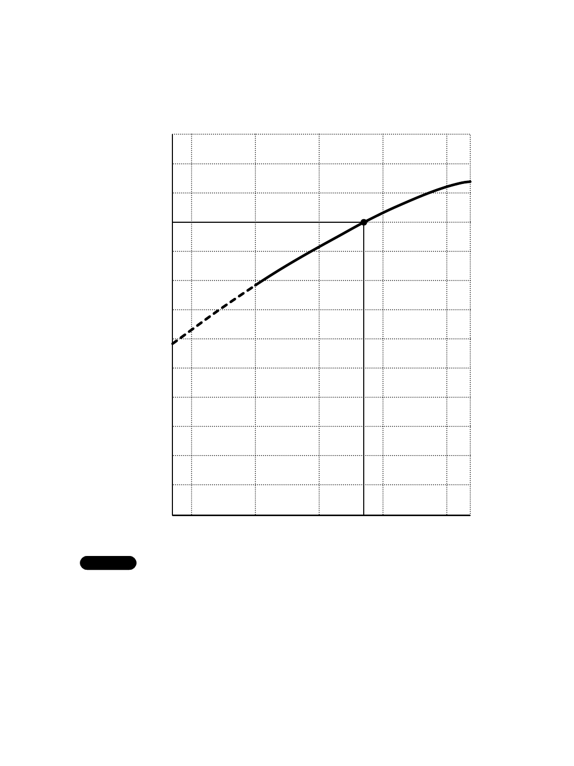
5-2. Heating Capacity (Heat pump Performance)
Model STB0823H1
17
Outdoor ambient temperature (°F DB)
0
10
20
30
40
50
60
70
80
90
100
110
120
Heating capacity ratio (%)
47 50 6040302017
1) ●… Point of rating condition
Black dot in the chart indicates the following rating condition.
Indoor: 70°F (21.1°C) D.B.
Outdoor: 47°F (8.3°C) D.B. / 43°F (6.1°C) W.B.
2) Above characteristics indicates heat pump heating operation, which does not include
elctric heater operation.
3) Because this air conditioner heats a room by drawing in the heat of the outside
air (heat pump system), the heating efficiency will fall off when the outdoor temperature
is very low, which consequently makes the room temperature decrease. At this time,
heat is provided by the electric heater instead of heat pump. See page 44 for detail.
NOTE
Fan speed : High
6. ELECTRICAL DATA
6-1. Electrical Characteristics
Model STB0810C1
Model STB1010C1
Model STB1020C1
Model STB1220C1
Outdoor Unit Complete Unit
Fan Motor Compressor
Performance at 230 / 208V 1-phase 60Hz
Rating Conditions Running Amps. A0.61 /0.64 5.49 /5.96 6.1 /6.6
Power Input kW 0.142 /0.132 1.208 /1.198 1.35 /1.33
Full Load Conditions Running Amps. A0.61 /0.64 6.29 /6.96 6.9 /7.6
Power Input kW 0.142 /0.132 1.428 /1.438 1.57 /1.57
Rating Conditions : Indoor Air Temperature 80°F (26.7°C) D.B. / 67°F (19.4°C) W.B.
Outdoor Air Temperature 95°F (35°C) D.B.
Full Load Conditions : Indoor Air Temperature 90°F (32.2°C) D.B. / 73°F (22.8°C) W.B.
Outdoor Air Temperature 110°F (43.3°C) D.B.
Outdoor Unit Complete Unit
Fan Motor Compressor
Performance at 230 / 208V 1-phase 60Hz
Rating Conditions Running Amps. A0.61 /0.64 4.39 /4.66 5.0 /5.3
Power Input kW 0.142 /0.132 0.998 /0.978 1.14 /1.11
Full Load Conditions Running Amps. A0.61 /0.64 4.99 /5.26 5.6 /5.9
Power Input kW 0.142 /0.132 1.118 /1.098 1.26 /1.23
Outdoor Unit Complete Unit
Fan Motor Compressor
Performance at 115V 1-phase 60Hz
Rating Conditions Running Amps. A1.26 9.34 10.6
Power Input kW 0.145 1.055 1.20
Full Load Conditions Running Amps. A1.26 11.04 12.3
Power Input kW 0.145 1.255 1.40
Outdoor Unit Complete Unit
Fan Motor Compressor
Performance at 115V 1-phase 60Hz
Rating Conditions Running Amps. A1.26 7.04 8.3
Power Input kW 0.145 0.795 0.94
Full Load Conditions Running Amps. A1.26 8.34 9.6
Power Input kW 0.145 0.935 1.08
Cooling only models
18
Model STB0811C1
Model STB1023C1
Model STB1123C1
Outdoor Unit Complete Unit
Fan Motor Compressor
Performance at 230 / 208V 1-phase 60Hz
Rating Conditions Running Amps. A0.61 /0.64 5.39 /5.86 6.0 /6.5
Power Input kW 0.142 /0.132 1.188 /1.178 1.33 /1.31
Full Load Conditions Running Amps. A0.61 /0.64 6.29 /6.86 6.9 /7.5
Power Input kW 0.142 /0.132 1.408 /1.408 1.55 /1.54
Rating Conditions : Indoor Air Temperature 80°F (26.7°C) D.B. / 67°F (19.4°C) W.B.
Outdoor Air Temperature 95°F (35°C) D.B.
Full Load Conditions : Indoor Air Temperature 90°F (32.2°C) D.B. / 73°F (22.8°C) W.B.
Outdoor Air Temperature 110°F (43.3°C) D.B.
Outdoor Unit Complete Unit
Fan Motor Compressor
Performance at 230 / 208V 1-phase 60Hz
Rating Conditions Running Amps. A0.61 /0.64 4.39 /4.66 5.0 /5.3
Power Input kW 0.142 /0.132 0.978 /0.958 1.12 /1.09
Full Load Conditions Running Amps. A0.61 /0.64 4.99 /5.26 5.6 /5.9
Power Input kW 0.142 /0.132 1.128 /1.088 1.27 /1.22
Outdoor Unit Complete Unit
Fan Motor Compressor
Performance at 115V 1-phase 60Hz
Rating Conditions Running Amps. A1.26 7.04 8.3
Power Input kW 0.145 0.775 0.92
Full Load Conditions Running Amps. A1.26 8.34 9.6
Power Input kW 0.145 0.945 1.09
Cooling & electric heating models
19
20
Model STB0823H1
COOLING
Outdoor Unit Complete Unit
Fan Motor Compressor
Performance at 230 / 208V 1-phase 60Hz
Rating Conditions Running Amps. A0.61 /0.64 3.59 /3.86 4.2 /4.5
Power Input kW 0.142 /0.132 0.798 /0.788 0.94 /0.92
Full Load Conditions Running Amps. A0.61 /0.64 4.29 /4.46 4.9 /5.1
Power Input kW 0.142 /0.132 0.948 /0.918 1.09 /1.05
Rating Conditions : Indoor Air Temperature 80°F (26.7°C) D.B. / 67°F (19.4°C) W.B.
Outdoor Air Temperature 95°F (35°C) D.B.
Full Load Conditions : Indoor Air Temperature 90°F (32.2°C) D.B. / 73°F (22.8°C) W.B.
Outdoor Air Temperature 110°F (43.3°C) D.B.
HEATING
Outdoor Unit Complete Unit
Fan Motor Compressor
Performance at 230 / 208V 1-phase 60Hz
Rating Conditions Running Amps. A0.61 /0.64 3.39 /3.66 4.0 /4.3
Power Input kW 0.142 /0.132 0.738 /0.738 0.88 /0.87
Full Load Conditions Running Amps. A0.61 /0.64 4.09 /4.51 4.7 /5.2
Power Input kW 0.142 /0.132 0.898 /0.888 1.04 /1.02
Rating Conditions : Indoor Air Temperature 70°F (21.1°C) D.B.
Outdoor Air Temperature 47°F (8.3°C) D.B. / 43°F (6.1°C) W.B.
Full Load Conditions : Indoor Air Temperature 80°F (26.7°C) D.B.
Outdoor Air Temperature 75°F (23.9°C) D.B. / 65°F (18.3°C) W.B.
Heat pump model
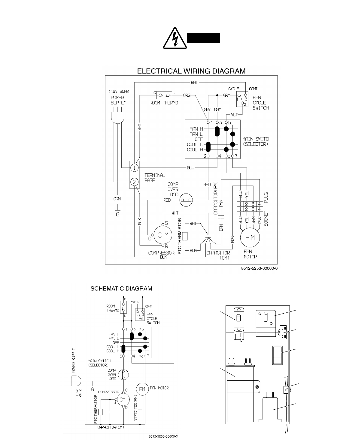
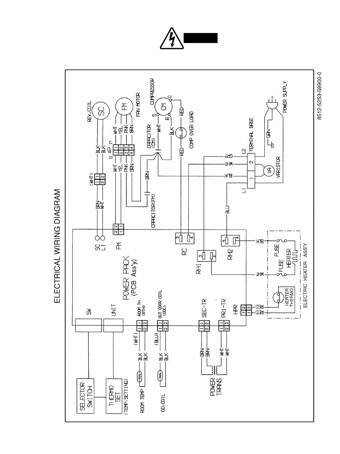
6-2. Electrical Wiring Diagrams
21
Models STB0810C1 STB1010C1
To avoid electrical shock hazard, be sure to
disconnect power before checking,
servicing and/or cleaning any electrical
WARNING
Room thermo Main switch
Capacitor
(FM)
Fancycle
switch
Capacitor
(CM)
Clip power
cord
Thermistor
LAYOUT FOR ELECTRIC PARTS
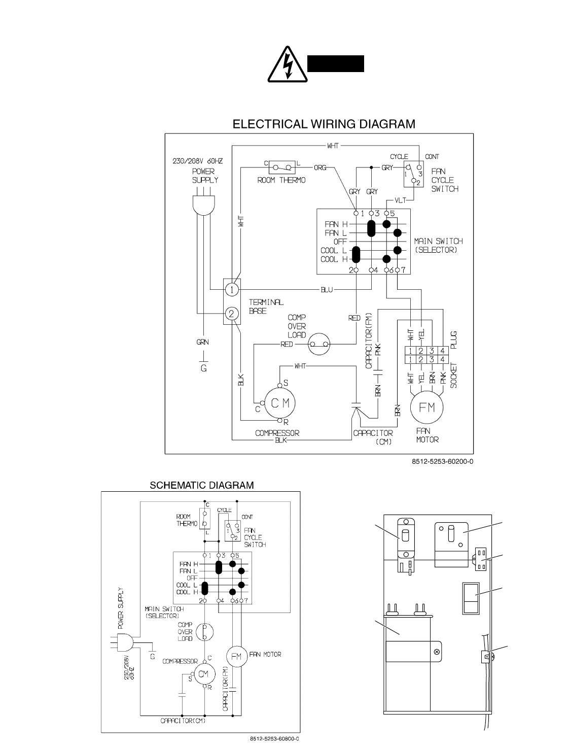
22
Models STB1020C1 STB1220C1
To avoid electrical shock hazard, be sure to
disconnect power before checking, servicing
and/or cleaning any electrical parts.
WARNING
Room thermo Main switch
Capacitor
(FM)
Fancycle
switch
Capacitor
(CM)
Clip power
cord
LAYOUT FOR ELECTRIC PARTS
23
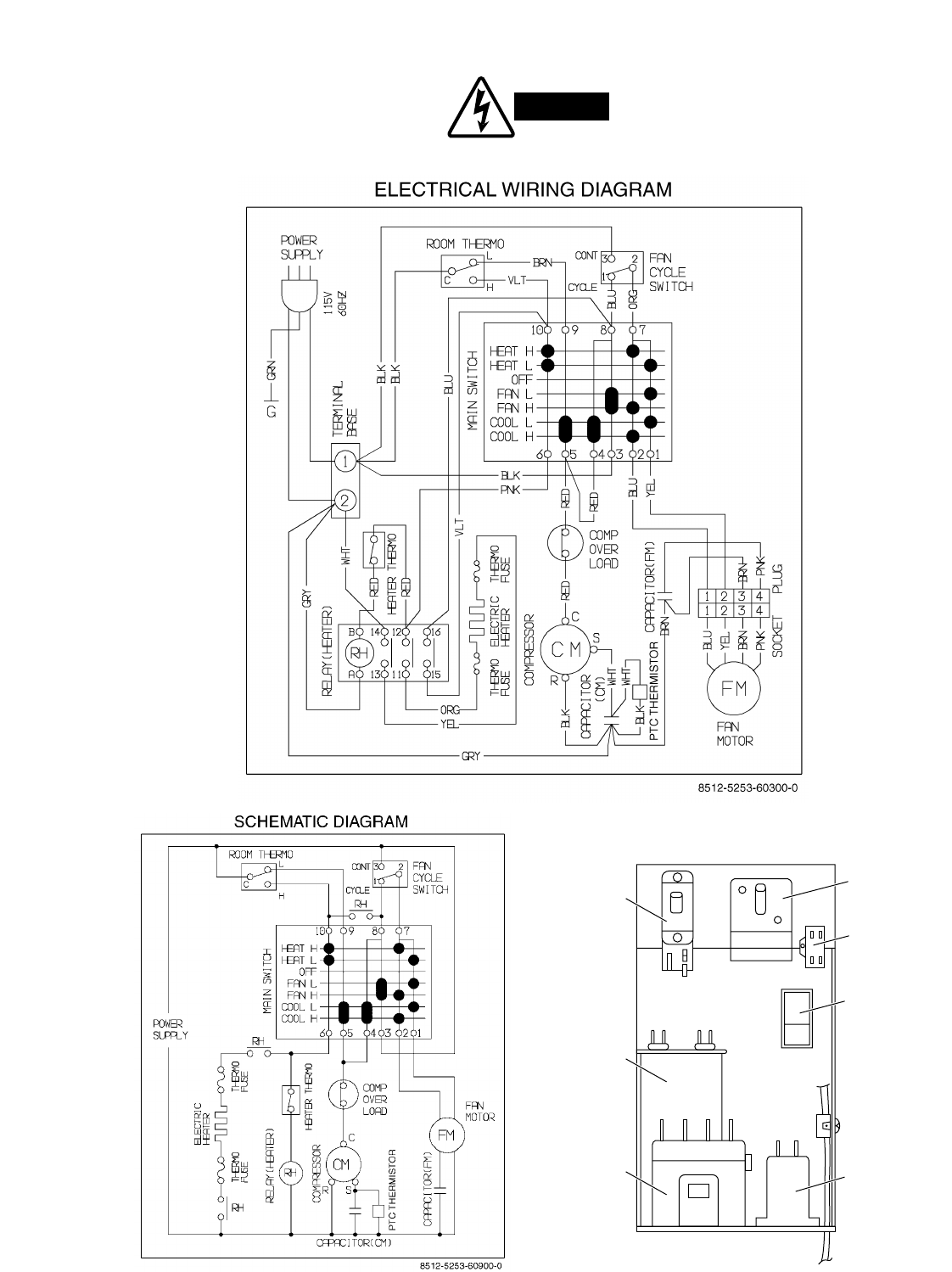
Model STB0811C1
To avoid electrical shock hazard, be sure to
disconnect power before checking, servicing
and/or cleaning any electrical parts.
WARNING
Room thermo Main switch
Capacitor
(FM)
Fancycle
switch
Thermistor
Capacitor
(CM)
Relay heater
LAYOUT FOR ELECTRIC PARTS
24
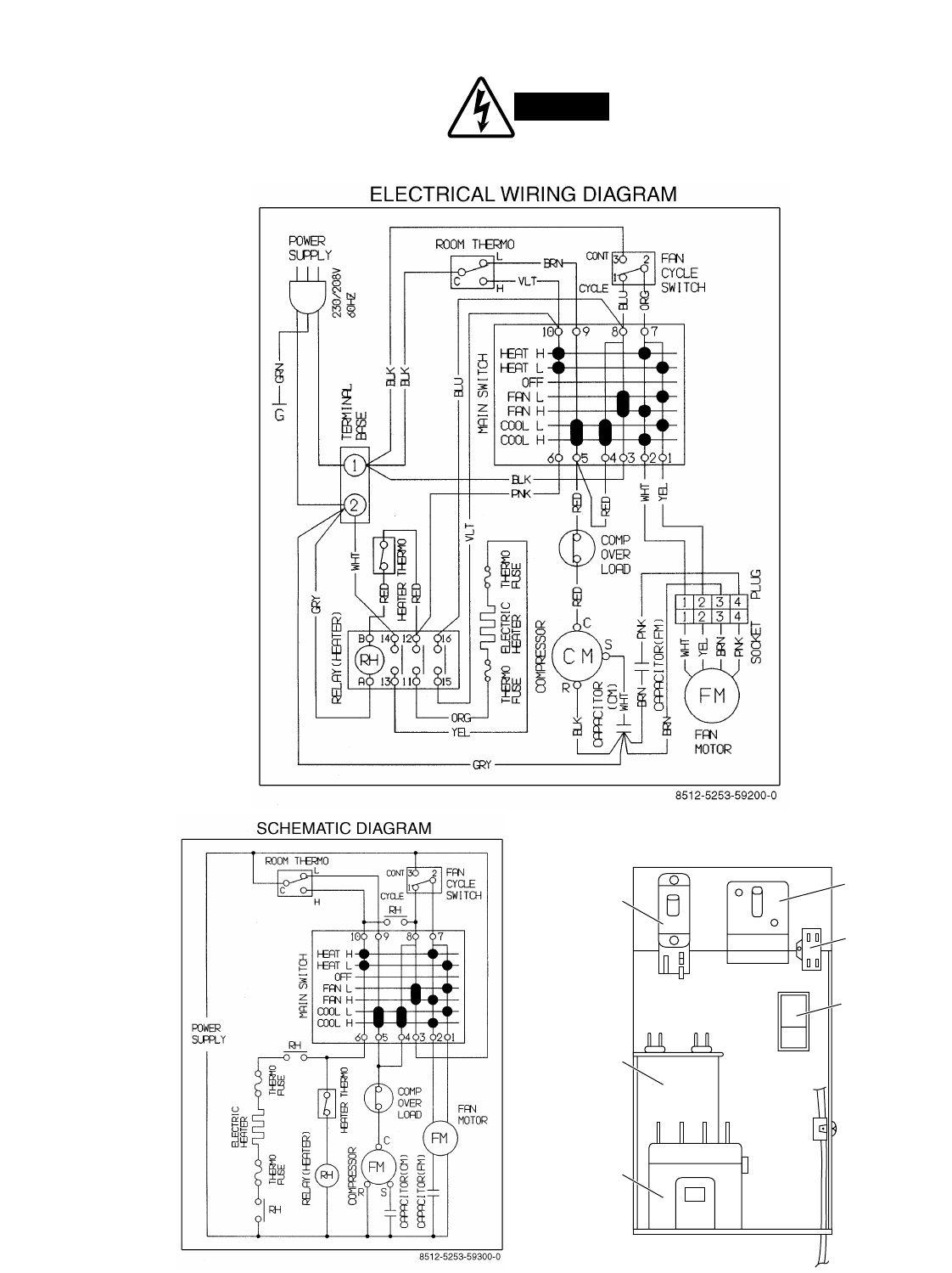
Models STB1023C1 STB1123C1
To avoid electrical shock hazard, be sure to
disconnect power before checking, servicing
and/or cleaning any electrical parts.
WARNING
LAYOUT FOR ELECTRIC PARTS
Room thermo Main switch
Capacitor
(FM)
Fancycle
switch
Capacitor
(CM)
Relay heater
25
Model STB0823H1
To avoid electrical shock hazard, be sure to
disconnect power before checking, servicing
and/or cleaning any electrical parts.
WARNING
26
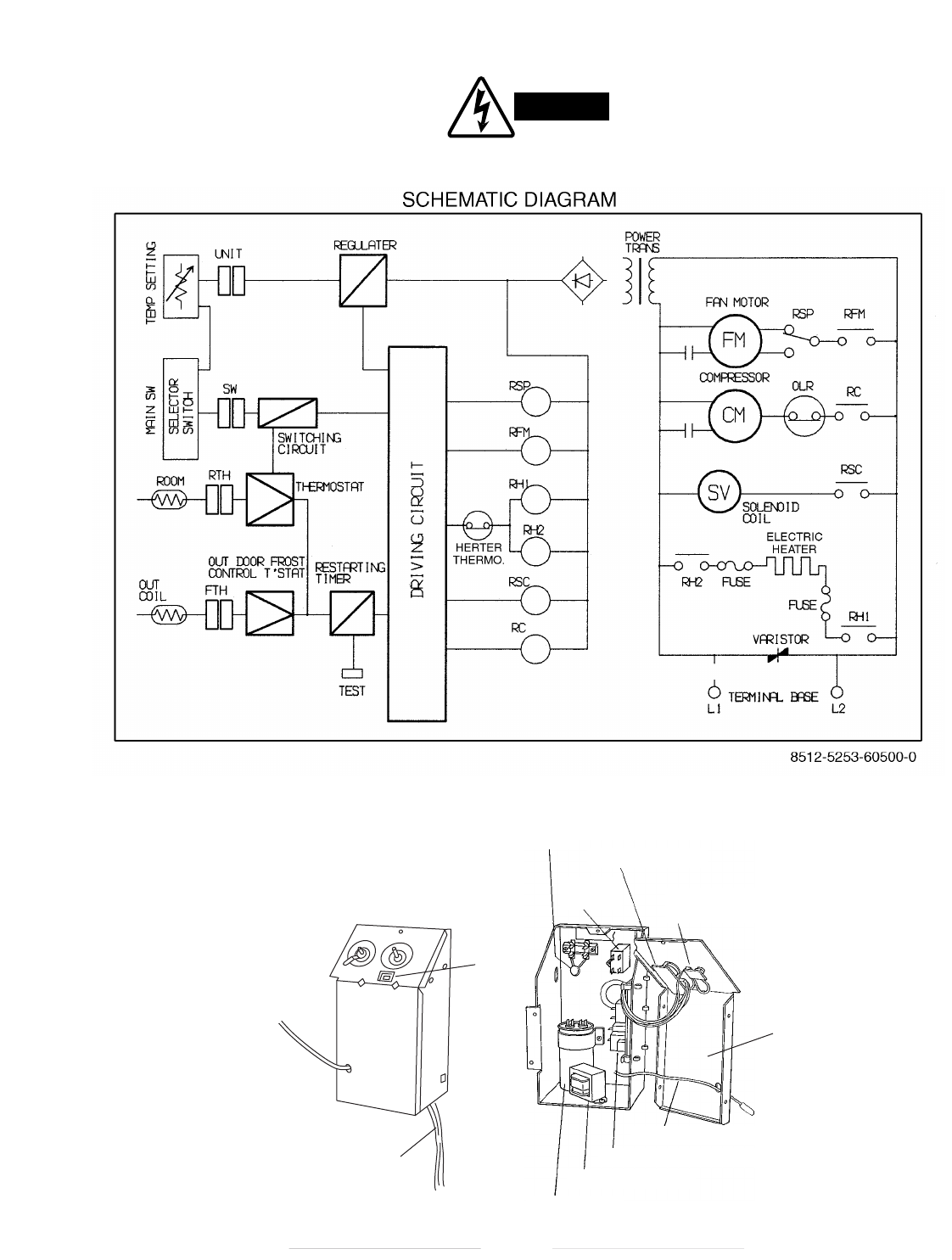
Model STB0823H1
To avoid electrical shock hazard, be sure to
disconnect power before checking, servicing
and/or cleaning any electrical parts.
WARNING
Capacitor
(FM)
Varistor
Capacitor (CM)
Power transformer
Power pack control PCB
Thermistor room temp.
Main control switch
Control switch
temp. setting
LAYOUT FOR ELECTRIC PARTS
BEFORE OPENING THE BOX
Fan
switch
Lid
Power cord
AFTER OPENING THE BOX
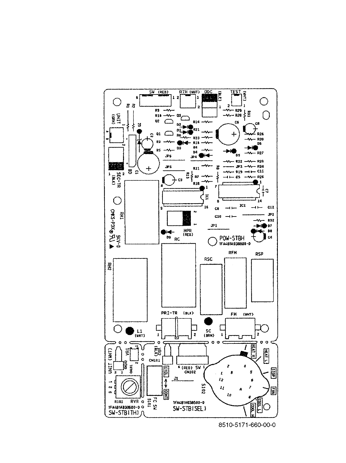
6-3. P.C.B. Ass'y (Printed Pattern)
27
POW–STBH (For model STB0823H1)
28
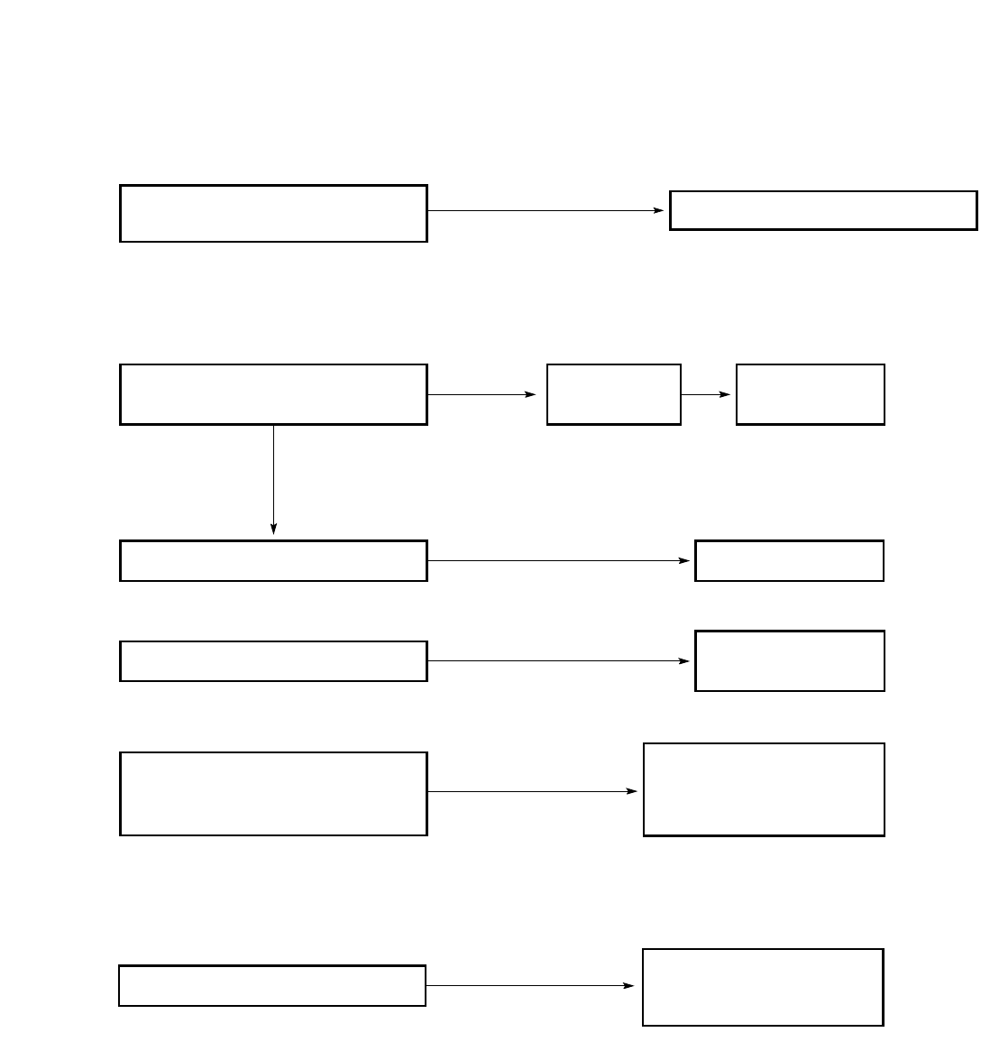
7. TROUBLESHOOTING
7-1. Check before and after troubleshooting
7-1-1. Check power supply.
●Check that voltage is in specified range (±10% of the rating).
●Check that power is being supplied.
7-1-2. Check lead wires and connectors.
●Check that coating of lead wires is not damaged.
●Check that lead wires and connectors are firmly connected.
●Check that wiring is correct.
WARNING
Hazardous voltage can cause ELECTRIC
SHOCK or DEATH. Disconnect power or turn
off circuit breaker before you start checking
or servicing.
7-2. Air conditioner does not operate.
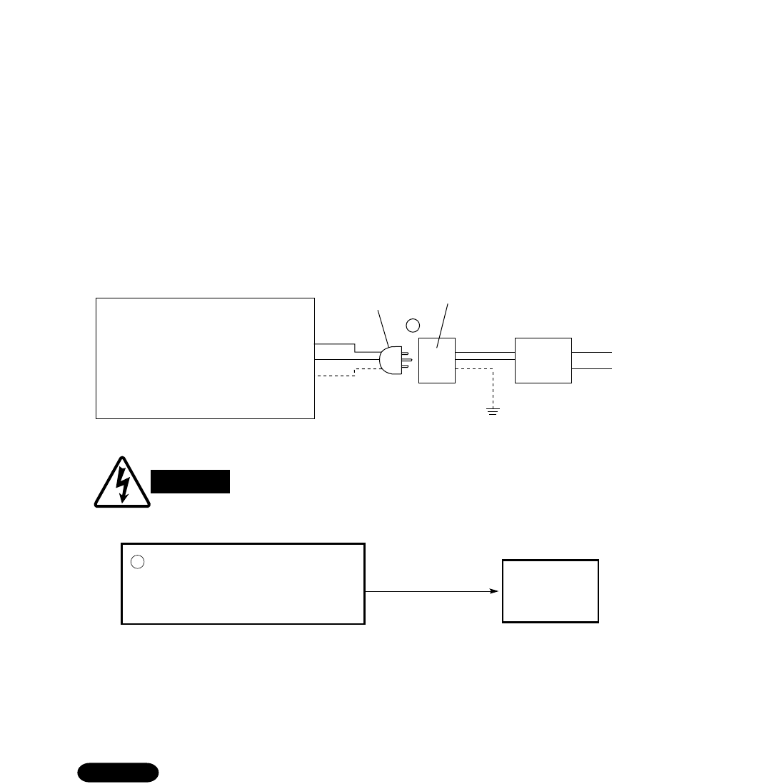
7-2-1. Circuit breaker trips (or fuse blows).
A. When the circuit breaker is set to ON, it is tripped soon. (Resetting is not possible.)
●There is a possibility of ground fault.
●Check insulation resistance.
If resistance value is 2MΩor less, insulation is defective (“NO”).
1. If any poorly insulated part is found, exclude that part from circuit with other parts properly connected, and then
measure insulation resistance of entire air conditioner again to locate defective part.
2. Replace defective part with new one.
NOTE
Measure insulation
resistance of electrical
parts.
(Example)
Compressor, Fan motor,
Capacitor, Relay etc.
NO
Set circuit breaker to OFF.
*
1Pull the power plug out of the
wall outlet.
Measure insulation resistance
of unit.
•
•
Insulation of
unit is
defective.
WARNING
Window type air conditioner
Power plug
Wall outlet
(Receptacle)
Power
supply
Circuit
breaker
Ground
1
29
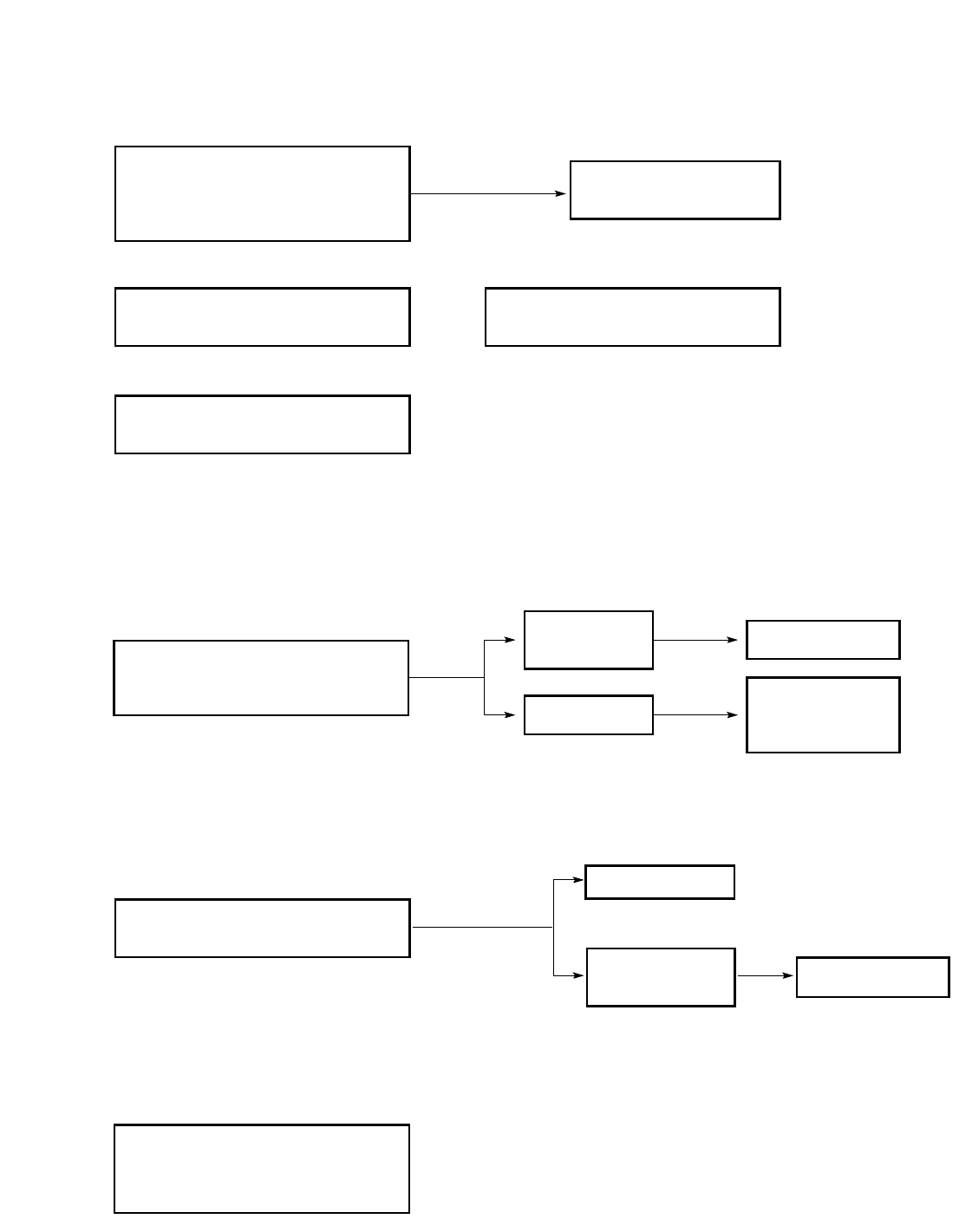
B. Circuit breaker trips in several minutes after turning the air conditioner on.
●There is a possibility of short circuit.
7-2-2. Neither fan motor nor compressor motor runs.
A. Power is not supplied.
B. Check "MODE selector" on the control panel.
C. Check transformer.
(Only for heat pump model)
•Check continuity of primary and
secondary winding to see if the lead
wires are disconnected.
•Check that MODE selector switch is
not set at "OFF".
Check PCB Ass'y.
If it is set at OFF.
Set to "COOL"
or "HEAT".
Set to "COOL".
(Cooling only models) and
(Cooling & electric heating models)
(Heat pump model)
NO
•Check power supply.
Power is being supplied to the unit.
Circuit breaker
is tripped.
Power failure
Reset breaker.
Wait for recovery
or contact power
company.
Replace with suitable
one (larger capacity).
•
•
•
NO
Check capacity of circuit breaker.
Capacity of circuit breaker is
suitable.
Measure resistance of fan motor
winding.
Measure resistance of compressor
motor winding.
•Measure resistance of 4-way valve's
winding.
(Only for heat pump model)
30
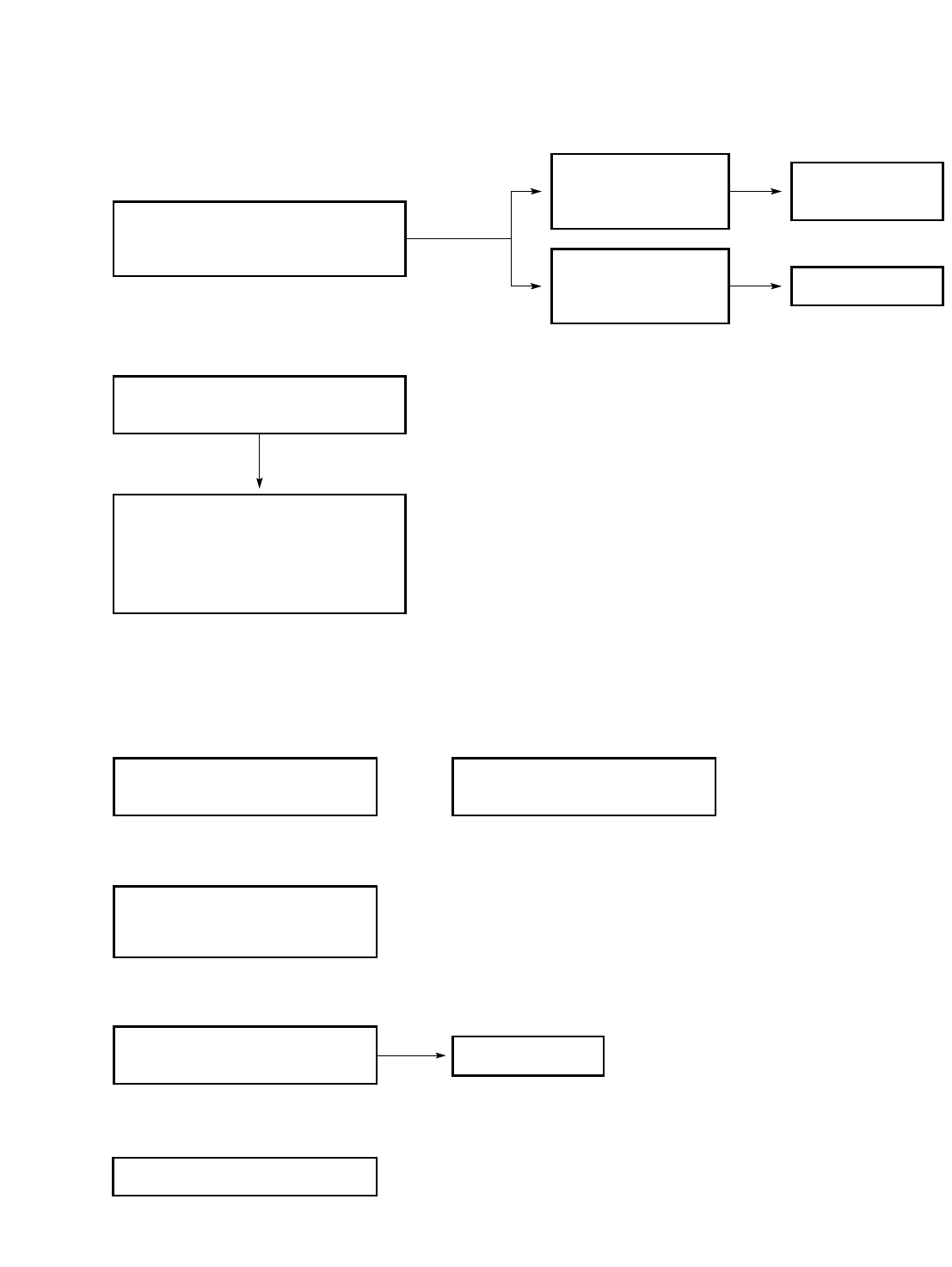
7-3. Some part of air conditioner does not operate.
7-3-1. Only fan does not run.
7-3-2. Electric heater does not work.
Both for (cooling & electric heating models) and (heat pump model)
•Measure resistance of electric
heater winding.
Blown
•Check continuity for thermal
fuses. Replace them.
•Measure coil resistance of
heater relay.
•Check PCB Ass'y. (Power pack)
(Only for heat pump model)
•Check to see if the circuit of
heater thermostat is opened or
closed ?
Fan cannot
be turned.
OK
•Check fan rotation.
Turn fan gently once or twice by
hand.
•Check fan casing
foreign matter on
inside.
Fan motor burnout
or foreign matter in
bearings.
Remove foreign
matter or repair.
Repair or replace.
•Measure resistance of fan motor
winding.
•Check fan motor capacitor and
4P-connectors (Socket and Plug).
•Check PCB Ass'y . (Power pack)
(Only for heat pump model)
31
7-3-3. Only compressor unit does not run.
A. Check setting temperature.
B. Check compressor and electrical parts.
●If the unit is turned off during cooling, DO NOT restart it immediately, as this
can damage it. Wait at least 3 minutes or so before starting it again.
●The compressor does not start up immediately even when the MODE selector
switch is set to COOL or HEAT (It starts operating in about 3 minutes).
●This is because rough 3-minute timer is built into the heat pump model in order
to protect the compressor. When operation is started up or restarted, the fan
operation begins immediately but the compressor starts operating after about
3-minute lag.
Heat pump model
Cooling & electric heating modelsCooling only models
CAUTION
•Check compressor motor
capacitor.
•Measure resistance of
compressor motor winding.
NO
YES
YES
Overload relay is working.
(OLR)
YES
Temperature of compressor
is abnormally high.
Refrigerant gas shortage. Charge refrigerant gas (R22).
Rotor may be locked up.
(Only for 115V models)
Check PTC thermistor.
•
NO
Is room temperature too low ?
Try to lower setting temperature by
thermostat knob cooler.
COOL mode
NO
Is room temperature too high ?
Try to raise setting temperature by
thermostat knob warmer.
HEAT mode (Only for heat pump model)
32
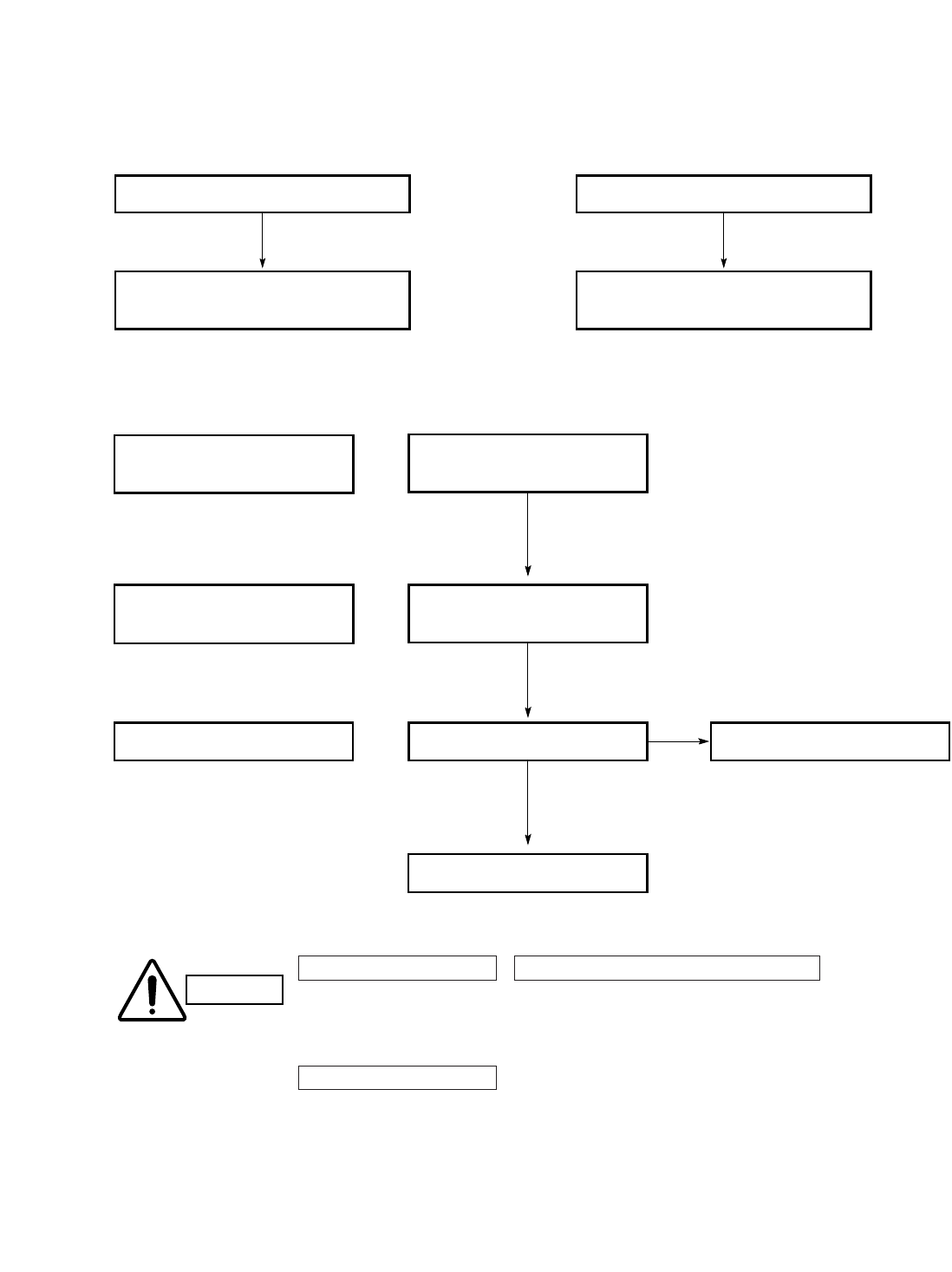
7-4. Air conditioner operates, but abnormalities are observed.
7-4-1. Operation does not switch from HEAT to COOL (or COOL to HEAT).
7-4-2. Poor cooling or heating.
7-4-3. Excessive cooling or heating.
NO
•Set temperature is suitable. Set temperature to higher or
lower value using thermostat.
Air filter is clogged.
Temperature
difference
is small.
YES
Temperature difference between
suction and discharge air is
large enough (In cooling operation:
approx. 14 °F or more).
Possibility of
gas shortage.
•Measure temperature of suction and
discharge air of air conditioner. Charge refrigerant
gas (R22).
Check for clogging of air filter.
•Fan speed is set to LOW.
Clean filter.
Set fan speed to HIGH.
•Review cooling load estimate,
if performance of air conditioner is
normal.
Reduce cooling or heating
load or replace the air
conditioner with larger
capacity.
•
Check PCB Ass'y . (Power pack)
OK
•Measure resistance of 4–way valve's
winding.
(Only for heat pump model)
33

7-5. If a sensor is defective. (Only for heat pump model)
7-5-1. Room temp. thermistor (RTH) is defective.
A. Open
When thermistor opens, the air conditioner will be in the following conditions
as the controller tries to detect extremely low room temperature.
a) In Cooling mode: The air conditioner soon stops and will not start again. (Thermo.OFF)
Compressor does not run.
b) In Heating mode: The air conditioner continues to operate. (Thermo.ON)
(Heat pump) Electric heater does not stop.
As a result, the room becomes too warm.
B. Short
When thermistor is short, the air conditioner will be in the following conditions
as the controller tries to detect extremely high room temperature.
a) In Cooling mode: The air conditioner continues to operate. (Thermo.ON)
Compressor does not stop.
As a result, the room becomes too cold.
b) In Heating mode: The air conditioner soon stops and will not start again. (Thermo.OFF)
(Heat pump) Neither compressor nor electric heater runs.
Definition of Open or Short Circuit of Sensor (Thermistor)
Open...A lead wire is broken or disconnected or the circuit inside the temperature sensor is open .
Short... The protective cover of a lead wire has been damaged, and the exposed wire is touching another metal
part, or both lead wires have become exposed and are touching each other. Alternatively, the circuit inside
the temperature sensor is closed.
NOTE
34
Temperature
sensor
Lead
wires
Thermistor Structure
35
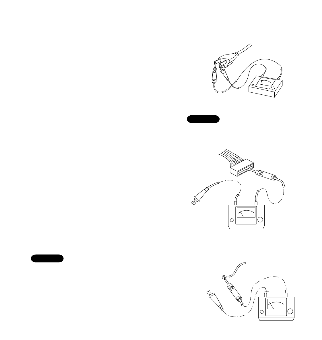
8-1. Measurement of Insulation
Resistance
●The insulation is in good condition if the resistance
exceeds 2MΩ.
8-1-1. Power Cord and Unit
Clamp the grounding prong of the power plug with a lead
clip of the insulation resistance tester and measure the
resistance by placing a probe on either of the two power
blade. (Fig. 1)
Then, also measure the resistance between the
grounding prong and other power blade. (Fig. 1)
8-1-2. Measurement of Insulation
Resistance for Electrical Parts
Disconnect the lead wires of the desired electric part
from terminal plate, switch, capacitor, etc. Similarly
disconnect the connector. Then measure the insulation
resistance.
(Figs. 2 to 3)
Refer to Electric Wiring Diagram.
If the probe cannot enter the poles because the hole is
too narrow then use a probe with a thinner pin.
NOTE
Power plug
Ground
Probe
Insulation tester
Fig. 1
Copper
tube or
metallic part
Clip
Insulation
tester
Probe
Fig. 2
Clip
Insulation
tester
Probe
Metallic
part
From fan motor,
compressor and
other parts
Fig. 3
Fig. 4
8. CHECKING ELECTRICAL COMPONENTS
The shape of the power plug may differ from that
of the air conditioner which you are servicing.
NOTE
36
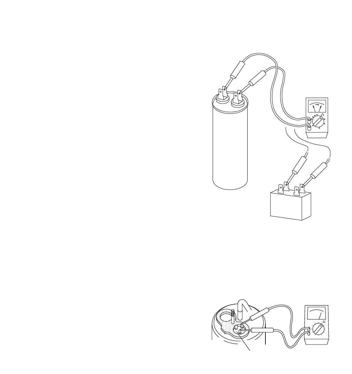
8-2. Checking Motor Capacitor
Remove the lead wires from the capacitor terminals, and
then place probes on the capacitor terminals as shown in
Fig. 4. Observe the deflection of the pointer, setting the
resistance measuring range of the multimeter to the
maximum value.
The capacitor is “good” if the pointer bounces to a great
extent and then gradually returns to its original position.
The range of deflection and deflection time differ
according to the capacity of the capacitor.
8-3. Checking Fan Motor Winding
Referring to the electrical diagram, disconnect fan motor
connectors, and measure the resistance between each
lead wire with a multimeter.
The multimeter should be set in the X1 range. If the fan
motor is hot, allow a few minutes until it gets cooled
down.
When the resistances between each lead wire are those
listed in "2-2. Major Component Specifications" the fan
motor should be normal.
Checking compressor motor winding can be done in the
similar manner.
Remove the terminal cover of the compressor motor,
setting the resistance measuring range of the multimeter
to "X1Ω" and check the continuity between each pair out
of the 3 terminals as shown in Fig. 5.
Refer to "2-2. Major Component Specifications" for coil
resistance.
8-6. Checking Thermistor
(Only for heat pump model)
Unplug the 2P connector connected to PCB Ass´y and
measure the resistance of the thermistor with a
multimeter, which is set in the X1 kΩrange.
If the thermistor is normal, the multimeter should read
approximately 15kΩat 32˚F.
Compressor motor
capacitor
Fan motor
capacitor
Multimeter
Fig. 4
Compressor motor
coil terminal
Multimeter
Fig. 5
8-4. Checking Compressor Motor Winding
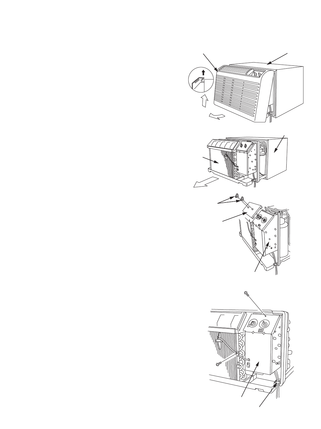
37
9-1. Removing Front Grille
1) Pull the bottom part of the front grille toward you.
(Fig. 1-➀)
2) Lift up and unhook the grille to remove it. (Fig. 1-➁)
9-2. Removing Wall Sleeve
(1) While supporting the bottom part of the unit, pull it
out of the wall sleeve. (Fig. 2)
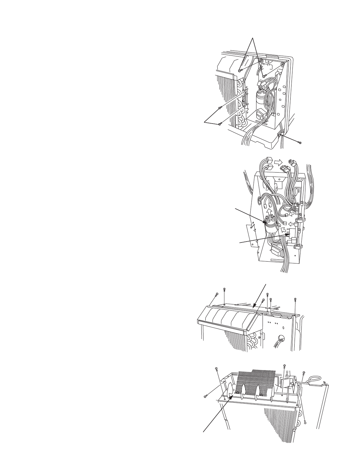
9-3. Removing Electrical Component
Box
(1) Remove knobs and the control panel from the
electrical component box.(Fig. 3)
(2) Remove the screws holding the lid of the electrical
component box, and also remove the wire clamp
holding the lead wires. (Fig. 4)
Fig. 4
Lid
Wire clamp
Fig. 3
Knob
Control
panel
Electrical compornent box
Fig. 2
Unit
Wall sleeve
Fig. 1
Front grille
➀
➁
Wall sleeve
9. DISASSEMBLY PROCEDURE
38
(3) Remove the following screws. (Fig. 5)
➀2 screws holding the component box
➁2 screws holding the ventilator knob
➂1 screw holding the power supply cord
(4) Disconnect the wiring connectors and lead wires
connecting the following electrical parts in the
electrical component box.(Fig. 6)
• Compressor motor capacitor
• Fan motor capacitor
9-4. Removing Electric Heater
(1) Remove the 6 screws holding the top cover plate.
(Fig. 7)
(2) Remove the 5 screws holding the blade Ass´y.
(Fig. 8)
Fig. 8
Blade Ass´y
Fig. 7
Top cover plate
Fig. 6
Fan motor capacitor
Compressor motor
capacitor
Fig. 5
➁
➀
➂
39
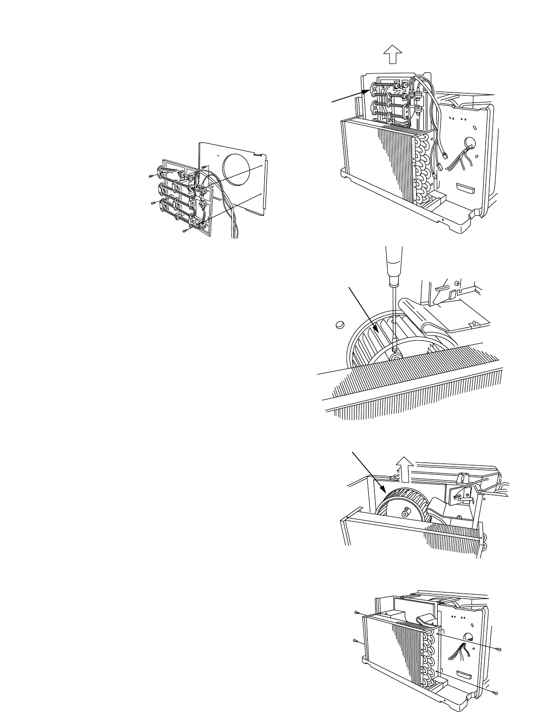
(3) Lift the electrical heater up out of the unit. (Fig. 9)
(4) Remove the 4 screws holding the electric heater
and take off the evaporator’s casing plate. (Fig. 10)
9-5. Removing Blower Wheel
(1) Remove the electric heater.
Refer to “9-4. Removing Electric Heater.”
(2) Loosen the bolt holding the blower wheel on the
motor shaft. (Fig. 11)
(3) Remove the blower wheel from the unit. (Fig. 12)
9-6. Removing Evaporator
(1) Remove the top cover plate and blade Ass´y.
Refer to “9-4. 1) and 2) Removing Electric Heater.”
(2) Remove the screws holding the evaporator.
(Fig. 13)
Fig. 13
Fig. 12
Blower wheel
Fig. 11
Blower wheel
Fig. 9
Electric
heater
Fig. 10
40
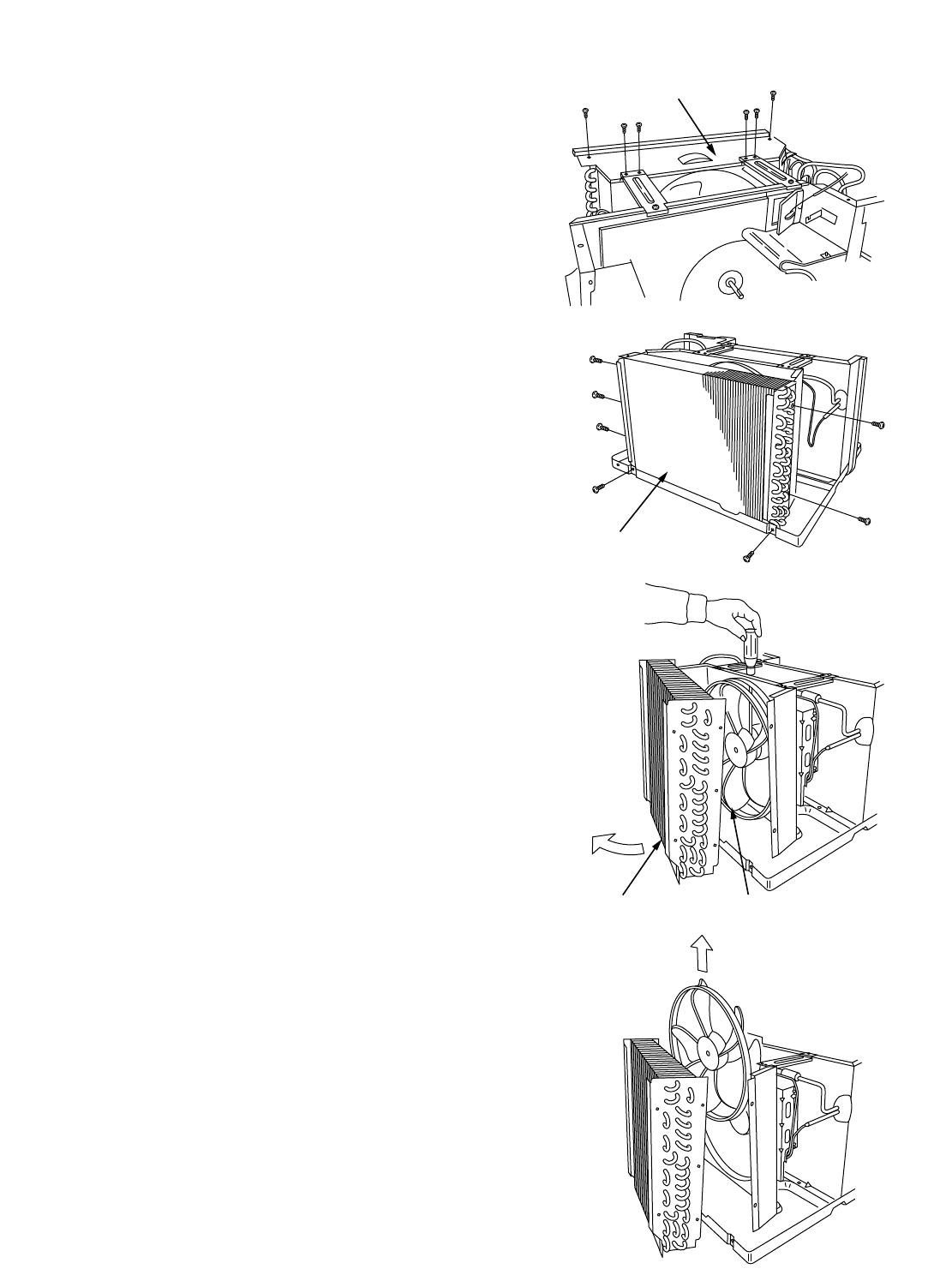
9-7. Removing Condenser
(1) Remove the screws holding the condenser casing.
(Fig. 14)
(2) Remove the screws holding the condenser.
(Fig. 15)
(3) Hold the lower part of the condenser with both
hands and tilt slightly, then lift up carefully to avoid
distorting the copper tube.
9-8. Removing Propeller Fan
(1) Remove the condenser.
Refer to “9-7. Removing Condenser.”
(2) Loosen the bolt holding the propeller fan on the
motor shaft. (Fig. 16)
(3) Remove the propeller fan from the motor shaft.
(Fig. 17)
Fig. 17
Fig. 16
Condenser Propeller fan
Fig. 15
Condenser
Fig. 14
Condenser casing
41
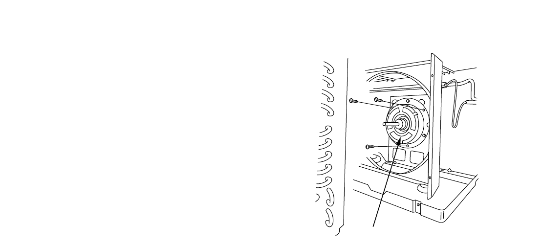
9-9. Removing Fan Motor
(1) Remove the condenser.
Refer to “9-7. Removing Condenser.”
(2) Remove the propeller fan.
Refer to “9-8. Removing Propeller Fan.”
(3) Remove the 3 screws of the fan motor mounting
plate. (Fig. 18)
Fig. 18
Fan motor
42
10. FUNCTION
10-1. Room Temperature Control
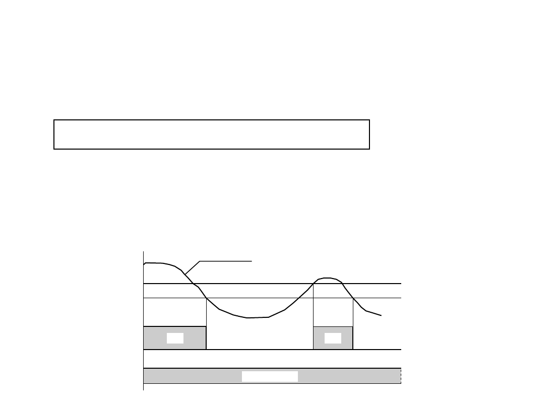
Room temperature control is obtained by cycling the compressor ON and OFF.
■Cooling
●Thermo. ON : When the room temperature rises above T + 4°F (T°F is set temperature).
Compressor ➞ON
●Thermo. OFF : When the room temperature falls below set temperature T°F.
Compressor ➞OFF
ON
ON
T °F
T+4 °F
set temp.
Compressor
Fan motor Set speed
Room temp.
OFFOFF OFF
Cooling Only Model
Models STB0810C1 STB1010C1 STB1020C1 STB1220C1
43
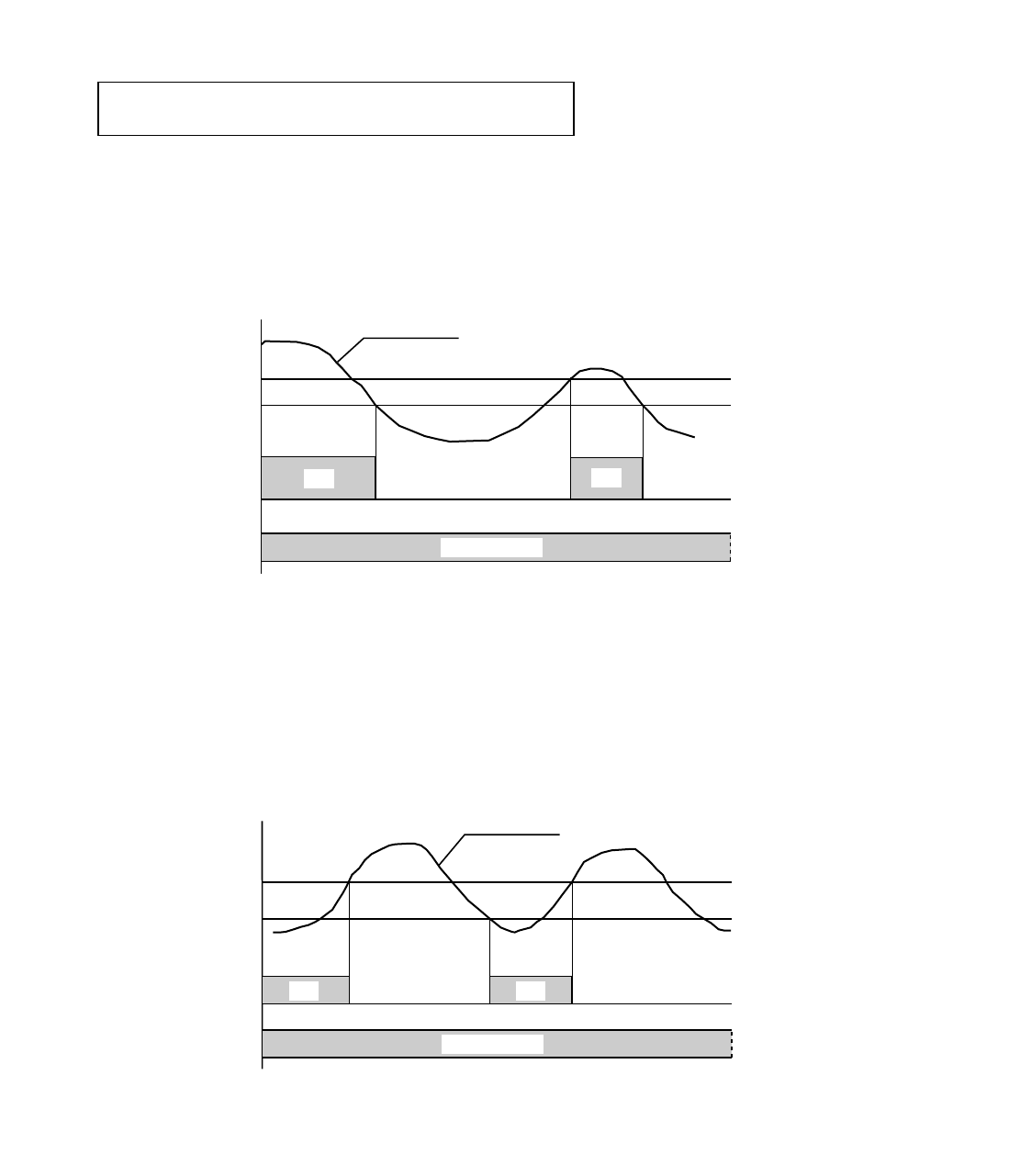
■Cooling
●Thermo. ON : When the room temperature rises above T + 4°F (T°F is set temperature).
Compressor ➞ON
●Thermo. OFF : When the room temperature falls below set temperature T°F.
Compressor ➞OFF
■Heating
●Heater ON : When the room temperature falls below T – 4°F (T°F is set temperature).
Heater ➞ON
●Heater OFF : When the room temperature rises above set temperature T°F.
Heater ➞OFF
T °F
T–4 °F
set temp.
Heater
Fan motor
ONON
Set speed
Room temp.
OFF OFF
ON
ON
T °F
T+4 °F
set temp.
Compressor
Fan motor Set speed
Room temp.
OFFOFF OFF
Cooling & Electric Heating Model
Models STB0811C1 STB1023C1 STB1123C1
44
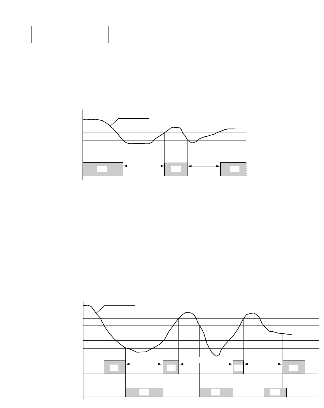
■Cooling
●Once the compressor stops, it will not start running again for about 3 minutes.
●Thermo. ON : When the room temperature rises above T + 1°F (T°F is set temperature).
Compressor ➞ON
●Thermo. OFF : When the room temperature falls below set temperature T°F.
Compressor ➞OFF
■Heating (Except during defrosting operation)
●Once the compressor stops, it will not start running again for about 3 minutes.
●Thermo. ON : When the room temperature falls below T°F (T°F is set temperature).
Compressor ➞ON
●Thermo. OFF : When the room temperature rises above T + 1°F.
Compressor ➞OFF
●Changeover to Heater ON : When the room temperature falls below T – 4°F, the unit turns off heat pump
operation and electric heater comes on instead of compressor.
●Changeover to Heat pump : When the room temperature rises above T – 3°F, the unit resumes heat pump
operation and compressor comes on instead of electric heater.
ON
ONON ON
ON ON
ON
ON
3 minutes
or more
T °F
T–3 °F
T+1 °F
T–4 °F
set temp.
Compressor
Heater
3 minutes 3 minutes
Room temp.
OFF OFF OFF OFF
OFFOFF OFFOFF OFF OFF
ONON ON
T °F
T+1°F
set temp.
Compressor
3 minutes
or more 3 minutes
Room temp.
OFF OFF
Heat Pump Model
Model STB0823H1
45
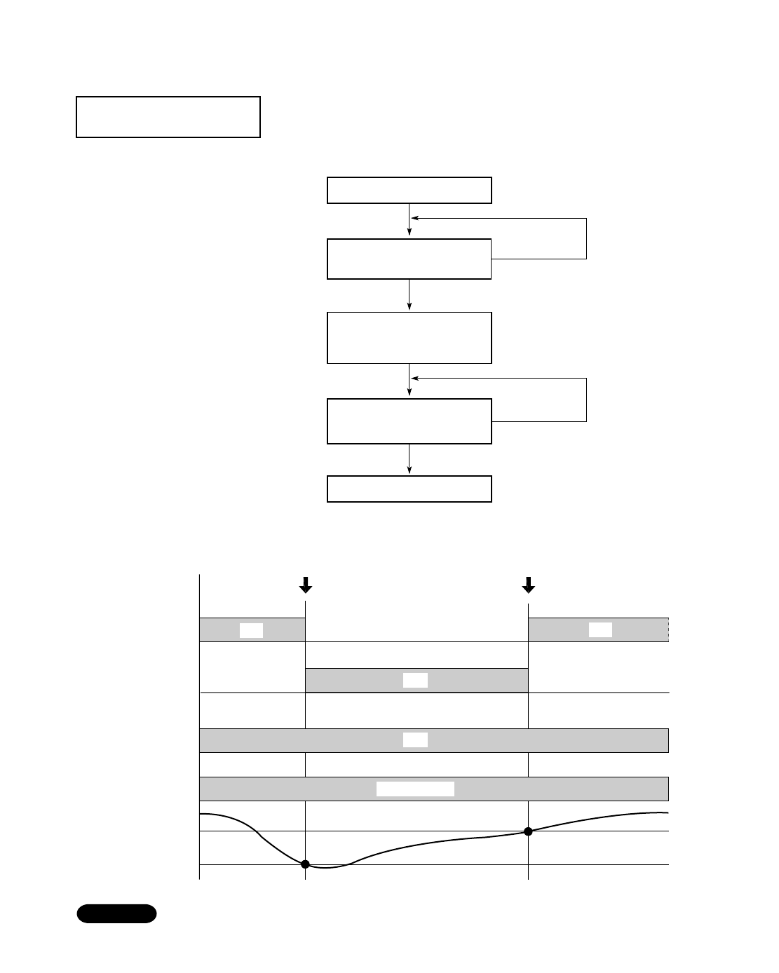
10-2. Defrosting Operation (Heating)
■ Defrosting Flowchart
■ Defrosting Mode Timing Chart
Once the air conditioner enters defrosting mode, it will not release defrosting until the
outdoor heat exchanger coil temperature rises above 39°F. During this period, heat is
provided by electric heater instead of by the heat pump.
NOTE
Outdoor heat
exch coil
temp.
Release of defrostingStart of defrosting
39 °F
14 °F
ON
Solenoid coil
(4-way valve)
Compressor OFF
ON ON
ON
Electric heater ON
ON
Fan motor
OFF OFF
Set speed
YES
YES
Temperature of outdoor heat
exchanger coil is blow 14°F.
Temperature of outdoor heat
exchanger coil is higher than
39°F.
Defrosting begins
Compressor ON
Release of defrosting
NO
NO
●Compressor ➞ OFF
●Electric Heater ➞ ON
Heat Pump Model
Model STB0823H1
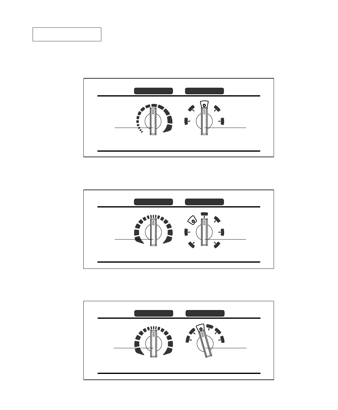
■ Heat Pump Model
Model STB0823H1
HIGH
THERMOSTAT SELECTOR
LOW OFF FAN
HEAT
COOLERWARMER
Thermostat Mode
selector
HEAT LOW
COOL
HIGH
COOL
■ Cooling & Electric Heating Model
Models STB0811C1 STB1023C1 STB1123C1
HIGH
THERMOSTAT SELECTOR
LOW
LOW
OFF
FAN
FAN
HEAT
COOLERWARMER
HEAT LOW
COOL
HIGH
HIGH
COOL
Thermostat Mode
selector
■ Cooling Only Model
Models STB0810C1 STB1010C1 STB1020C1 STB1220C1
THERMOSTAT SELECTOR
LOW OFF
FAN
FAN
COOLER
LOW
COOL
HIGHHIGH COOL
Thermostat Mode
selector
Control Panel
APPENDIX
46
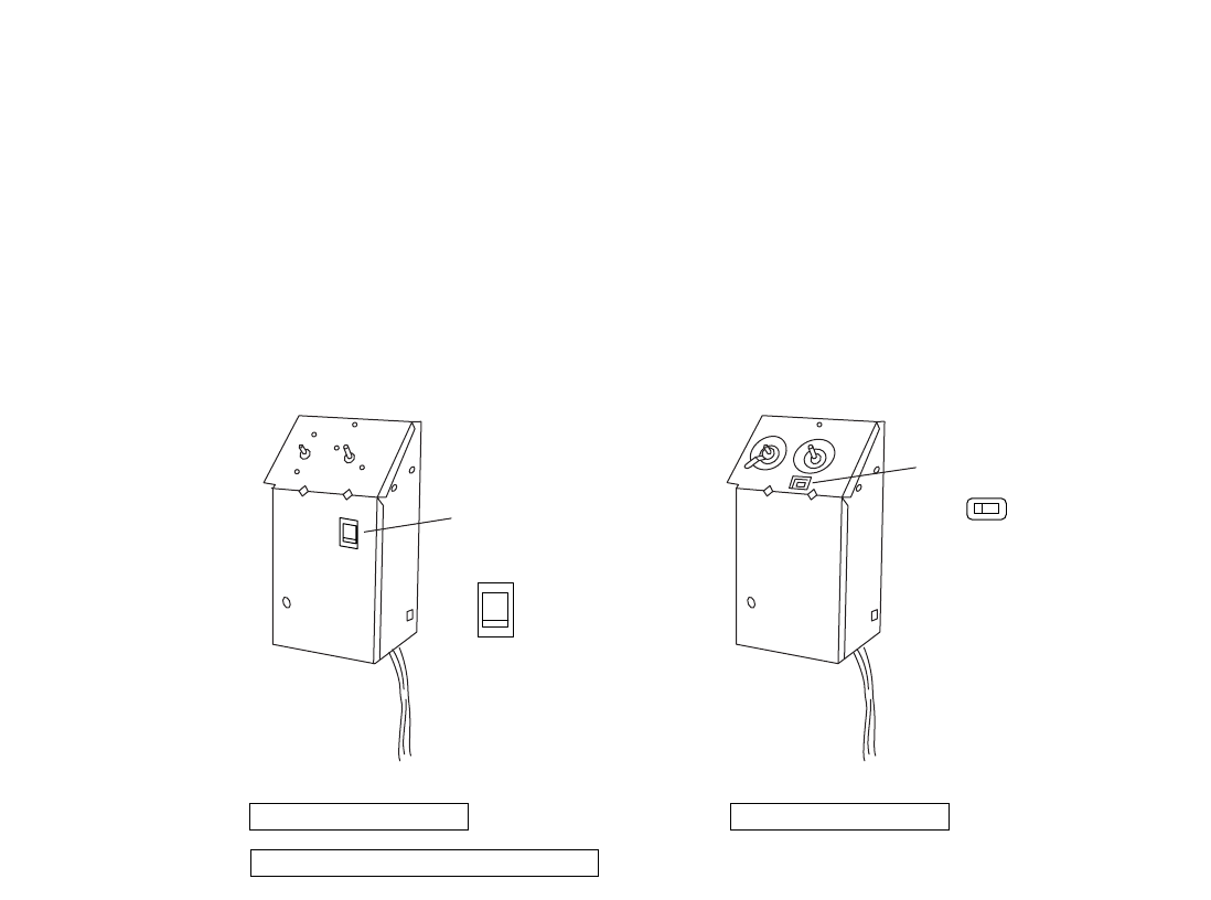
Cooling Only Model
Fan switch
Cooling & Electric Heating Model
Heat Pump Model
Fan switch
FAN
CONT
CYCLE
CONTCYCLE
The location of Fan Switch differ according to models.
When set to CYCLE, fan operation synchronizes with that of compressor's (or heater's) thermo ON and
thermo OFF, thereby saving power. When set to CONT, fan continues to operate regardless of thermo
ON or thermo OFF condition.
Fan Switch
47

For Parts or Service Contact
SANYO HVAC SERVICE CENTER
SANYO Fisher Service Company
1165 Allgood Road, Suite 22, Marietta, GA 30062 U.S.A.
300 Applewood Crescent, Concord, Ontario, L4K 5C7, CANADAMay. / 2001 / 850 Printed in Japan
