Sargent Instructions For Installing 1431 Series Door Closers (with Hold Open Arms 'H'/UH/HZ/HZA/PH9) A7140F Low Res
User Manual: Sargent Instructions for installing 1431 Series Door Closers (with Hold Open Arms 'H'/UH/HZ/HZA/PH9) Instruction Sheets
Open the PDF directly: View PDF ![]() .
.
Page Count: 8
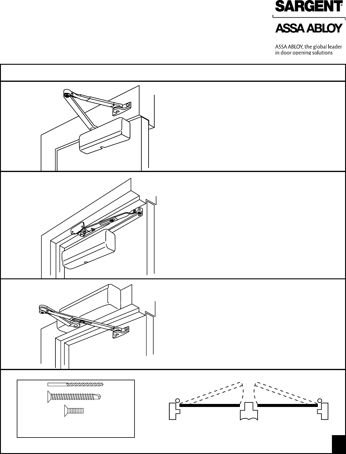
Installation Instructions based on Application and Arm type
Standard Mounting Application -
H arm
For Standard Application - the Door Closer is mounted
on the hinge side of door (see page 2)
Parallel Arm Application -
PH9 Arm
For Parallel Arm Application - the Door Closer is mounted
on the stop side of door (see page 4)
Top Jamb Application -
H, HZ & HZA Arm
For Top Jamb Application - the Door Closer is mounted on the
frame on the stop side of the door (see page 6)
LEFT
HAND DOOR
RIGHT
HAND DOOR
HINGE SIDE HINGE SIDE
STOP SIDESTOP SIDE
1
INSTRUCTIONS FOR
1431 Door Closer with Hold Open Arms
1431 SERIES ADJUSTABLE FROM SIZE 1 THRU 6
FOR INSTALLATION ASSISTANCE CALL SARGENT AT 1-800-727-5477 / www.sargentlock.com
Copyright © 2010, Sargent Manufacturing Company, an ASSA ABLOY Group company.
All rights reserved. Reproduction in whole or in part without the express written permission
of Sargent Manufacturing Company is prohibited.
A7140F 1
IMPORTANT NOTICE
PRE-DRILL 3/32” HOLES FOR SELF-TAPPING SCREWS
OR TAP #12-24 FOR MACHINE SCREWS
+
or
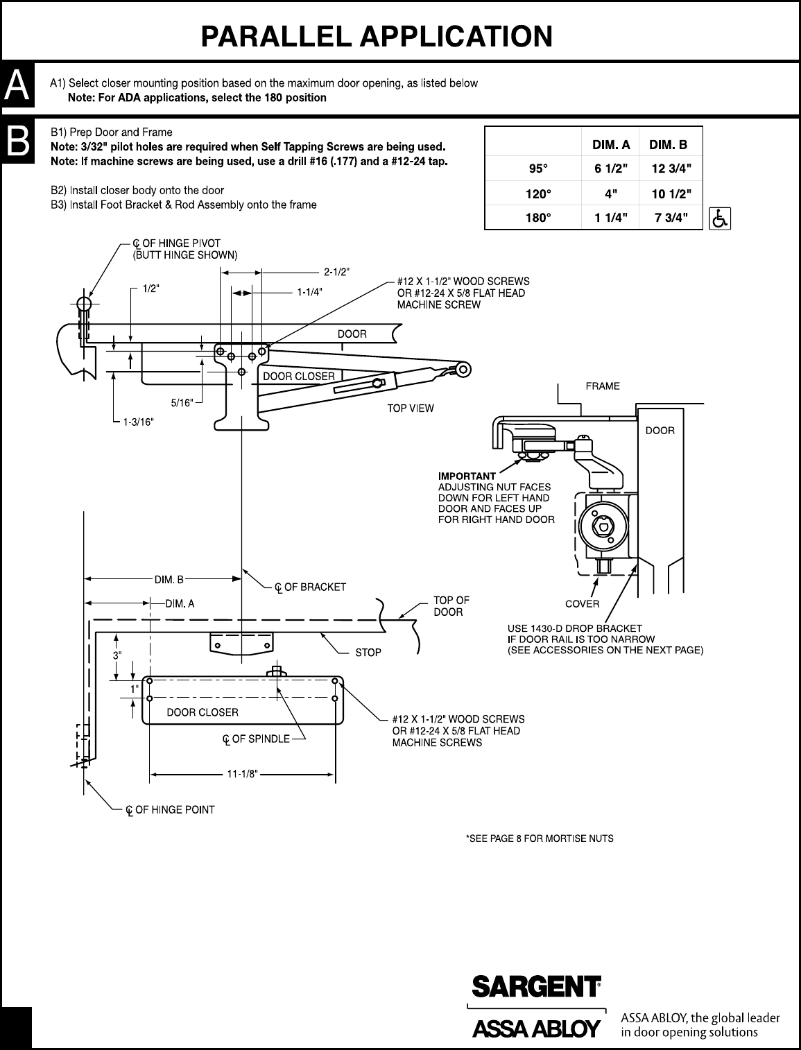
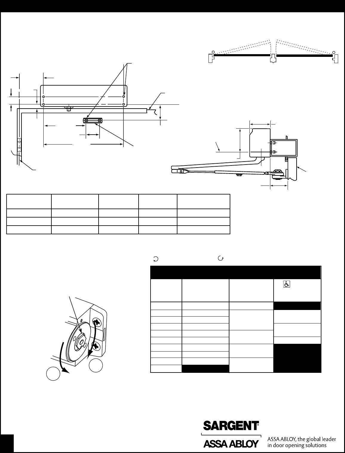
A1) Select closer mounting position based on the maximum door opening, as listed below
Note: For ADA applications, select the 160ϒ position
1
5
4
MAIN
ARM
INDEX MARK
ON SPINDLE
RIGHT HAND DOOR
POSITION OF
MAIN ARM WHEN
ASSEMBLING
TO SPINDLE
C
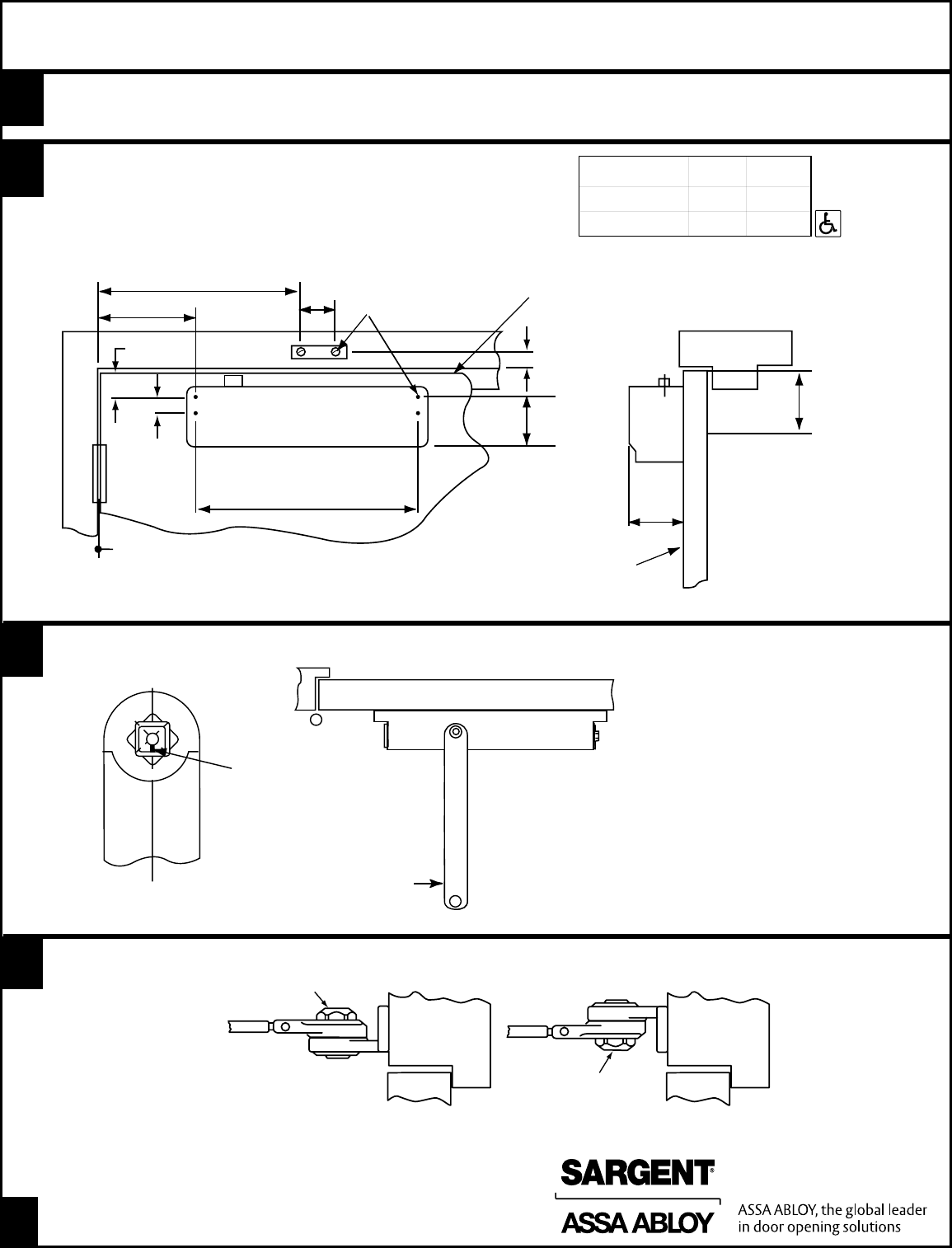
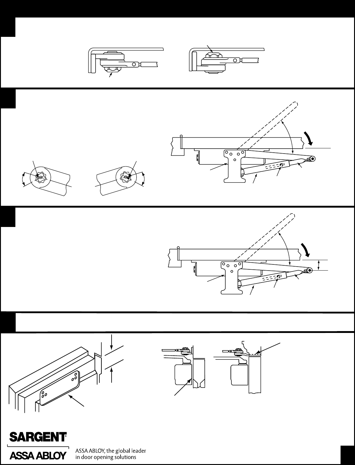
B1) Prep door and frame
Note: 3/32" pilot holes are required when Self Tapping Screws are being used
Note: If machine screws are being used, use a drill #16 (.177) and a #12-24 tap
B2) Install closer body onto the door
B3) Install Foot & Rod Assembly onto the frames
C1) Install main arm on the closer with the index mark on the spindle aligning with the # 2 on the main arm (as shown)
A
B
2
3
**If Butt, Frame and Wall Conditions Permit
Door Will Open 180ϒ
MAXIMUM DOOR
OPENING
120ϒ7 1/2" 13 1/4"
160ϒ** 4 1/4" 10"
DIM. A DIM. B
C OF HINGE PIVOT
L
#12 X 1 1/2 SCREWS OR
#12-24 X 5/8 FLAT HEAD
MACHINE SCREW*
TOP OF DOOR
DOOR CLOSER
DIM. “B”
DIM. “A”
11
1
⁄
8
"
1"
2-1/2"
7
⁄
8
"
1
1
⁄
4
"
2
9
⁄
16
"
*SEE PAGE 8 FOR MORTISE NUTS
RIGHT HAND DOOR ILLUSTRATED. SAME DIMENSIONS APPLY FOR LEFT HAND DOOR.
2
5
⁄
8
" MIN
TOP RAIL
FRAME
DOOR
FACE OF DOOR
RAILS TO 1
3
⁄
4
" MAY BE
USED PROVIDED FRAME
DOES NOT PROJECT
BEYOND FACE OF DOOR
2
5
⁄
16
"
STANDARD APPLICATION
DAttach hold open foot to frame with adjusting nut facing down for left hand door or up for right hand door, as illustrated below
FRAME FRAME
NUT FACES DOWN
NUT FACES UP
LEFT HAND
DOOR SHOWN
RIGHT HAND
DOOR SHOWN
2
Copyright © 2010, Sargent Manufacturing Company, an ASSA ABLOY Group company.
All rights reserved. Reproduction in whole or in part without the express written permission
of Sargent Manufacturing Company is prohibited.
A7140F
ACCESSORIES INFORMATION
1431-W corner bracket closer is mounted on bracket which is attached to door jamb
on stop side of door
Use this application for exterior doors to keep the closer inside of building; Also may be
used to obtain full 180ϒ door opening
MORTISE NUTS FOR BOLTING THRU THE DOOR ARE FURNISHED WHEN ORDERED
STANDARD APPLICATION
E1) Opening the door slightly, slide rod into swivel arm and then close the door
E2) With the door closed, position the swivel arm so that it is 90º to the door surface
E3) Tighten the arm screw securely
E
Adjust closer as required (See page 8 for details).
F
1
5
4
MAIN
ARM
INDEX MARK
ON SPINDLE
2
3
1430-J COVER PLATE
MAY BE USED WHEN CLOSER IS MOUNTED
ON A NARROW RAIL TO IMPROVE APPEARANCE
WHEN CLOSER IS VIEWED THRU GLASS
H8 MORTISE FOOT
FOR USE WHERE THE
STANDARD SURFACE
APPLIED FOOT CANNOT
BE ATTACHED TO THE
TOP CASING OR WHERE
APPEARANCE IS A
MAJOR FACTOR
RIGHT HAND DOOR
ROD
90ϒ
ARM
SCREW
POSITION OF MAIN
ARM WHEN ASSEMBLING
TO SPINDLE
HOLD
OPEN ARM
Copyright © 2010, Sargent Manufacturing Company, an ASSA ABLOY Group company.
All rights reserved. Reproduction in whole or in part without the express written permission
of Sargent Manufacturing Company is prohibited.
A7140F 3
MAXIMUM DOOR
OPENING
4
Copyright © 2010, Sargent Manufacturing Company, an ASSA ABLOY Group company.
All rights reserved. Reproduction in whole or in part without the express written permission
of Sargent Manufacturing Company is prohibited.
A7140F
INSTRUCTIONS FOR INSTALLING PARALLEL ARM APPLICATION
CLOSER MOUNTED ON
STOP SIDE OF DOOR
ACCESSORIES INFORMATION
CLOSER IS MOUNTED ON PLATE WHEN
TOP RAIL IS TOO NARROW
1430-D DROP BRACKET
2 1/2" MIN.
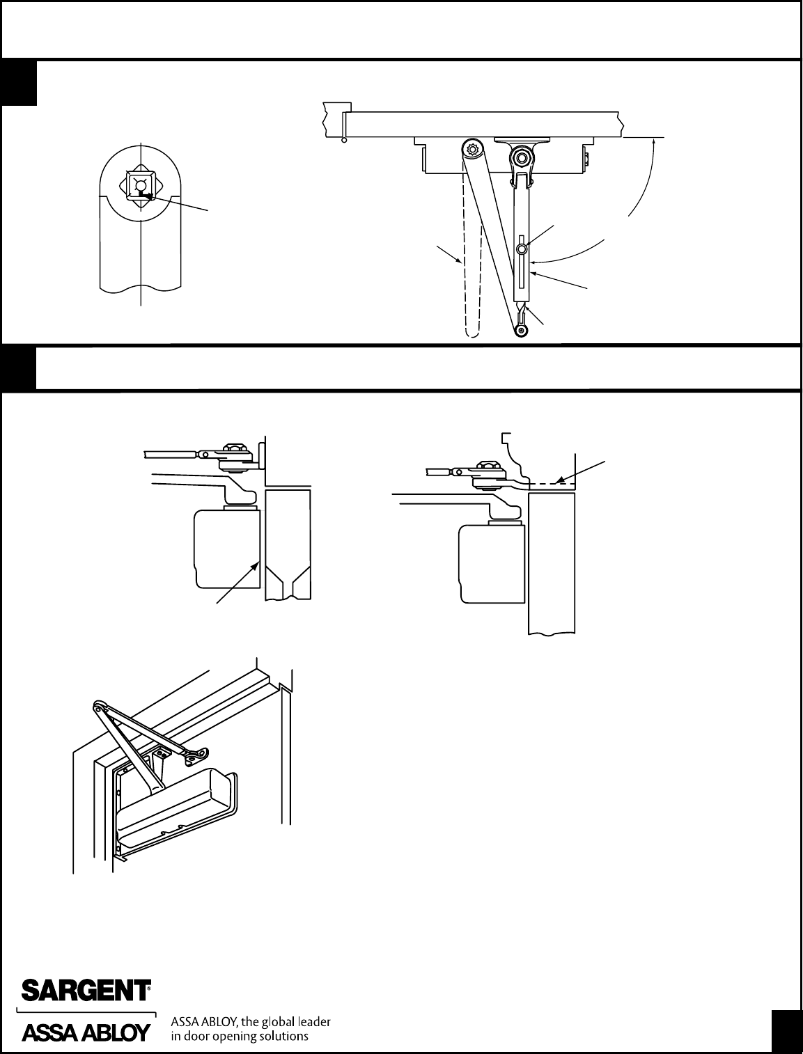
DD1) Install main arm on the closer with the index mark on
spindle aligned with the number on the arm
Note: Left Hand Doors -align index mark with the # 4
on the main arm (as shown)
Note: Right Hand Doors -align index mark with the # 5
on the main arm (as shown)
D2) This requires the spindle to be rotated
D3) Rotate the spindle on the bottom of the closer to align
index mark with the required number on the arm
E1) Opening the door slightly, slide rod into swivel arm and
then close the door.
E2) With the door in the closed position, swivel the arm so that
the pivot is an 1-1/2" off the door surface (as shown below)
E3) Tighten the arm screw securely
INDEX MARK
ON SPINDLE
INDEX MARK
ON SPINDLE
1
5
2
3
MAIN
ARM
45°45°
1
4
MAIN
ARM
3
E
Adjust closer as required. See page 8 for details.
F
4
2
5
Left Hand Door Right Hand Door
C
NUT FACES DOWN
NUT FACES UP
RIGHT HAND
DOOR SHOWN
LEFT HAND
DOOR SHOWN
Select degree of door opening required and attach door closer body to door (long end toward hinge) and foot bracket to frame (according to
illustration on “A” page 3). Use templates enclosed for special arms.
Mount hold open arm to bracket with adjusting screw facing down for left hand door, facing up for right hand door.
LEFT HAND DOOR
PRELOAD 45°
ARM
SCREW
ROD
FOOT BRACKET
HOLD
OPEN ARM
1430-J COVER PLATE
May be used when closer is mounted on
a narrow rail to improve appearance when
closer is viewed through glass
#8 MORTISE FOOT
For use where the
standard surface applied
foot cannot be attached
to the top casing or where
appearance is a major
factor
#H8 MORTISE FOOT
MORTISE NUTS FOR BOLTING THRU THE DOOR
ARE FURNISHED WHEN ORDERED
LEFT HAND DOOR
PRELOAD 45°
ARM
SCREW
ROD
FOOT BRACKET
HOLD
OPEN ARM
1-1/2"
Copyright © 2010, Sargent Manufacturing Company, an ASSA ABLOY Group company.
All rights reserved. Reproduction in whole or in part without the express written permission
of Sargent Manufacturing Company is prohibited.
A7140F 5
6
Copyright © 2010, Sargent Manufacturing Company, an ASSA ABLOY Group company.
All rights reserved. Reproduction in whole or in part without the express written permission
of Sargent Manufacturing Company is prohibited.
A7140F
LEFT HAND DOOR ILLUSTRATED
SAME DIMENSIONS APPLY FOR RIGHT HAND
DOOR MEASURE FROM HINGE C
L
INSTALLATION
INSTRUCTIONS CLOSER MOUNTED ON FRAME
ABOVE STOP SIDE OF A DOOR
TOP JAM APPLICATION
#2 x 1-1/2" WOOD SCREWS
OR #12-24 x 5/8" FLAT
HEAD MACHINE SCREWS
TOP OF DOOR
2-1/4"
DOOR CLOSER
5/8"
1"
11-1/8"
CLOSER FOOT
APPLIED TO
DOOR
3-3/8"
C OF HINGE PIVOT
DIM "A"
2-1/2"
L
2-9/16"
DEPTH OF REVEAL
C OF CLOSER
MOUNTING
SCREWS
L
2"
DOOR
SPRING POWER
ADJUSTING NUT
DECREASE
POWER
INCREASE
POWER
–+
FOR EXTERIOR DOORS AND WHERE STRONG DRAFT EXISTS INCREASE SPRING POWER AS NEEDED BY TURNING SPRING
ADJUSTING NUT CLOCKWISE. IF NECESSARY, DECREASE SPRING POWER TO MEET REQUIREMENTS BY TURNING SPRING
ADJUSTING NUT COUNTER CLOCKWISE.
* FOR EXTERIOR DOORS USE 1430 CLOSERS ONLY.
** CLOSERS ARE FACTORY SET FOR INTERIOR DOORS.
CW-CLOCKWISE CCW-COUNTER CLOCKWISE
SPRING ADJUSTMENT
ADJUST SPRING POWER ACCORDING TO CHART.
NUMBER OF TURNS OF SPRING POWER ADJUSTING NUT*
USE CHART AS GUIDE ONLY.
FACTORY**
SET
4-7 CW
7-10 CW
DOOR
WIDTH
(INCHES)
APPROXIMATE
DOOR WEIGHT
(POUNDS)
1430 DOOR
CLOSERS
24
30
32
36
40
42
44
46
48
OVER 48
80
110
115
130
150
155
165
170
180
1-3 CCW
FACTORY**
SET
1-3 CW
4-7 CW
7-10 CW
1431*
DOOR
CLOSERS
HINGE SIDE HINGE SIDE
STOP SIDE STOP SIDE
THIS IS A LEFT HAND DOOR THIS IS A RIGHT HAND DOOR
CLOSERS ARE NON-HANDED
ARM ASSEMBLY
TYPE
REVEAL DEPTH DIM. A MAX DOOR
OPENING
RANGE OF HOLD
OPEN
“H” ARM 0" TO 2" 5-3/4" 180° 80° - 180°
“HZ” ARM 2-1/8" TO 5" 6-1/2" 140° 80° - 140°
“HZA” ARM 5-1/8" TO 8" 7-1/4" 140° 80° - 130°
Copyright © 2010, Sargent Manufacturing Company, an ASSA ABLOY Group company.
All rights reserved. Reproduction in whole or in part without the express written permission
of Sargent Manufacturing Company is prohibited.
A7140F 7
INSTRUCTIONS FOR INSTALLING TOP JAMB
CLOSER MOUNTED ON FRAME
ABOVE STOP SIDE OF DOOR
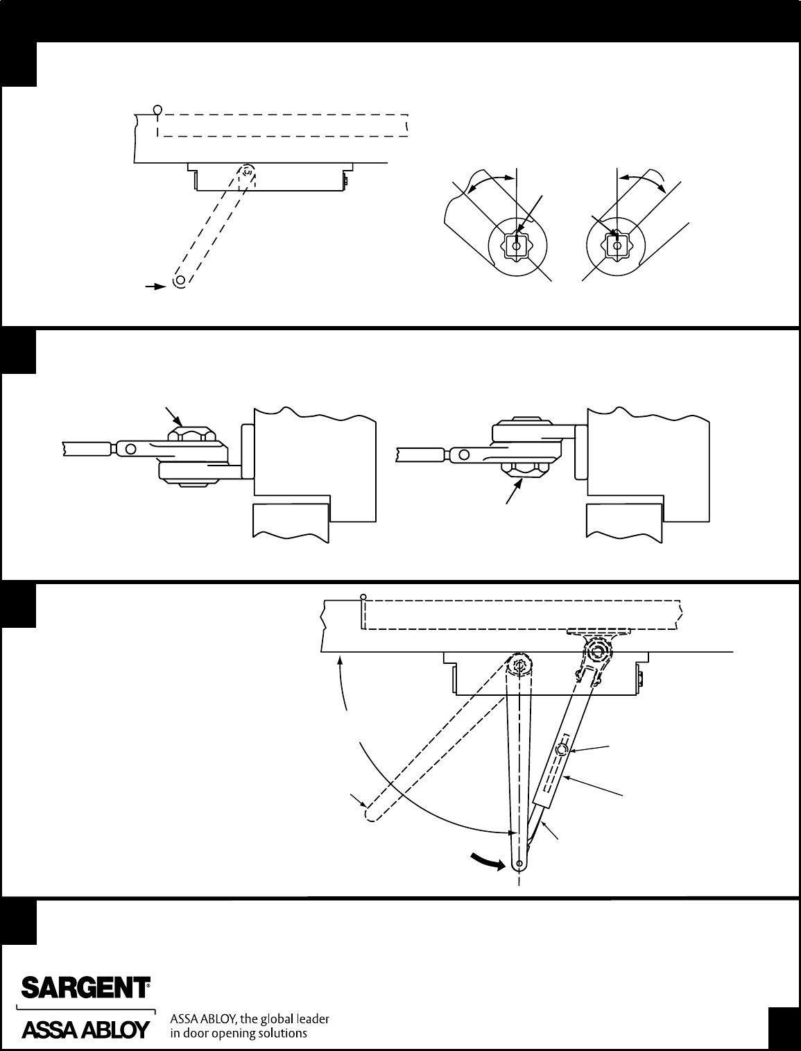
DD1) Install main arm on the closer with the index mark on spindle aligned with the number on the arm
Note: Left Hand Doors -align index mark with the # 3 on the main arm (as shown)
Note: Right Hand Doors -align index mark with the # 1 on the main arm (as shown)
F1) Opening the door slightly, slide rod into swivel
arm and then close the door
F2) With the door closed, position the main arm so
it is at 90º to the door surface
F3) Tighten the arm screw securely
F
Adjust closer as required. See page 8 for details.
G
INDEX MARK
ON SPINDLE
INDEX MARK
ON SPINDLE
1
5
4
2
3
MAIN
ARM
45°
1
5
4
2
3
45°
MAIN
ARM
LEFT HAND DOOR
POSITION
OF MAIN ARM
WHEN
ASSEMBLING
TO SPINDLE
E
FRAME FRAME
NUT FACES DOWN
NUT FACES UP
LEFT HAND
DOOR SHOWN
RIGHT HAND
DOOR SHOWN
Attach hold open foot to frame with adjusting nut facing down for left hand door or up for right hand door as illustrated below.
POSITION OF
MAIN ARM WHEN
ASSEMBLING
TO SPINDLE
ROD
HOLD
OPEN ARM
ARM
SCREW
LEFT HAND DOOR
RIGHT
ANGLE
RIGHT HAND
LEFT HAND
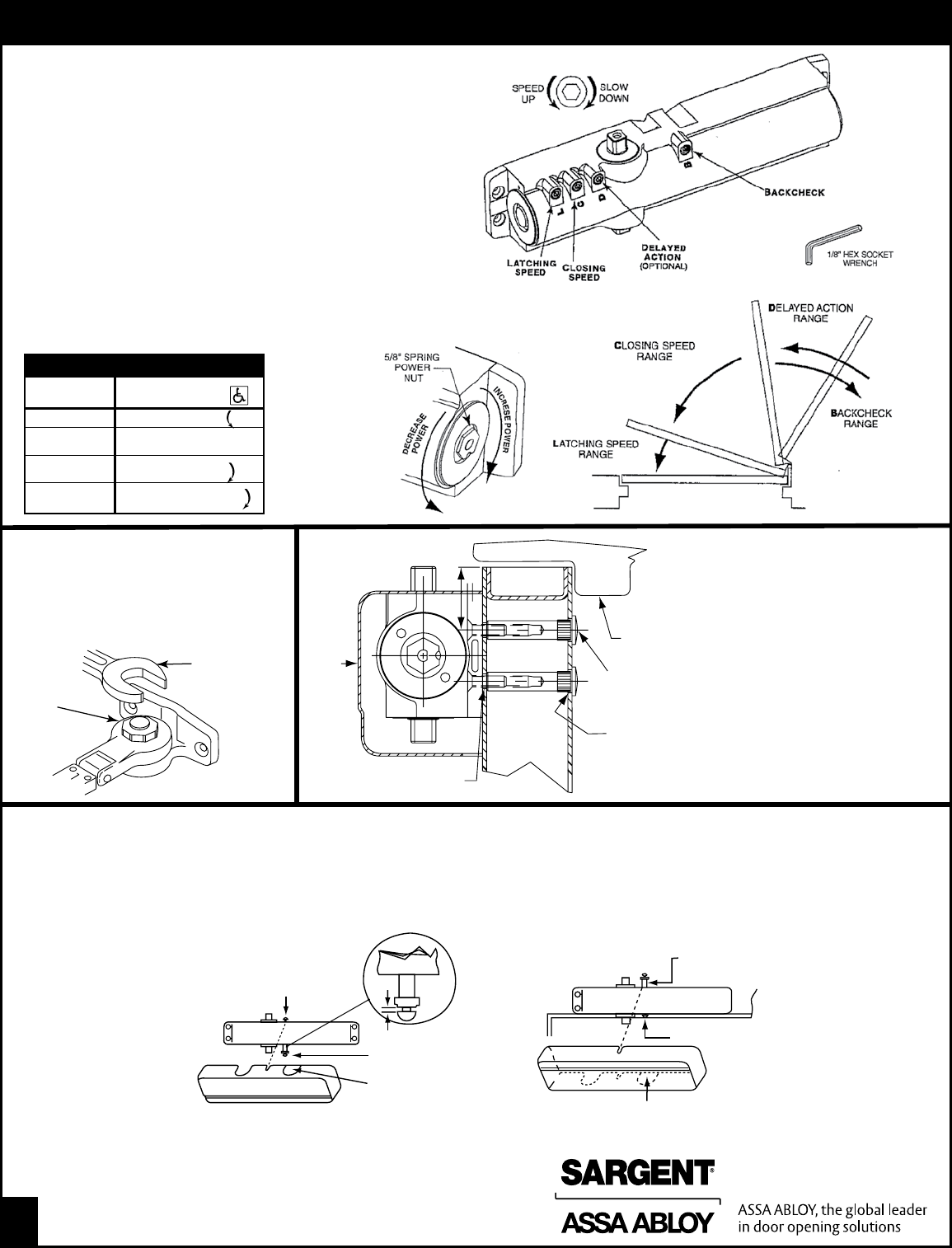
INSTALL COVER AS FOLLOWS:
FOR STANDARD AND PARALLEL ARM APPLICATION
•Screw short cover screw (#8-32 X 5/16) into top of case
approximately 2 turns
•Assemble plastic support and long cover screw (#8-32 X 1 1/4)
into bottom of case approximately 2 turns
•Hold support against case (approximately 2 turns)
between flange and screw head
•Position cover on closer and tighten screws
FOR TOP JAMB APPLICATION
•Assemble plastic support and long cover screw (#8-32 X11/4")
into top of case approximately 2 turns
•Screw short cover screw (#8-32 X 5/16") into bottom of case
approximately 2 turns
•Slide cover into gap between flange and screw head. Position cover
on closer and tighten screws
GAP
SHORT COVER SCREW
PLASTIC SUPPORT AND
LONG COVER SCREW
INSERT IS REMOVABLE.
PLACE IN UNUSED OPENING
SHORT COVER SCREW
PLASTIC SUPPORT AND
LONG COVER SCREW
INSERT IS REMOVABLE. PLACE IN UNUSED OPENING
RIGHTHAND
ILLUSTRATED
FINAL ADJUSTMENT AND REGULATING PROCEDURE
FRAME
UNREINFORCED
DOOR
COVER
DOOR
STOP
MORTISE
NUTHEAD
DRILL
3/8" DIA.
HOLE FOR
MORTISE
NUTBODY
DRILL 1/4" DIA.
HOLE FOR MOUNTINGSCREWS
1. For top jamb and corner bracket
applications: The door closer foot
will be attached to the door in a
manner similar to that shown for
mounting the closer body.
2. The appropriate mortise nuts
and screws will be suppled based
on door thickness.
Door construction must provide a
bridge type reinforcement to prevent
the door rail from collapsing when
through-bolts are tightened.
Adjustment hold open arm
Slight tightening or loosening of hold
open nut changes holding position of door.
Note: To protect wall, trim and closer, use a door stop
located 10°beyond hold open position but not beyond
the max. door opening shown on instructions.
HOLD
OPEN
NUT
USE 15/16"
WRENCH TO
ADJUST NUT
Minimum recommended door closing time is 6 Seconds for
doors opened to 90 degrees.
Use 1/8” hex (Allen) wrench to adjust valves as needed.
Closing and latching speeds:
Turn valves clockwise to slow down or counterclockwise to
speed up door movement.
Backcheck:
To regulate the intensity of back check action, turn valve clockwise
to increase or counterclockwise to decrease checking.
CAUTION: Set valve for slight cushioning effect; closer can be
damaged if the checking action is too abrupt. Never use
the backcheck as a door stop. Always use a door stop to stop
the door.
Delayed action feature (Optional feature on some models):
“Delayed action” provides slow door closing through the
delayed action range. Turn valve clockwise to slow down or
counterclockwise to speed up door movement.
8
Copyright © 2010, Sargent Manufacturing Company, an ASSA ABLOY Group company.
All rights reserved. Reproduction in whole or in part without the express written permission
of Sargent Manufacturing Company is prohibited.
A7140F
DOOR WIDTH 1431 DOOR CLOSER
(INCHES)
24-30 TURN nut 1-3
30-36 FACTORY SET
36-42 TURN nut 1-4
42-48 TURN nut 7-9
NUMBER OF TURNS OF SPRING POWER ADJUSTING NUT
Adjusting door
to close due to
high draft
conditions may
exceed ADA
standards.
Consult local
ordinances
when fire doors
are involved
