Sargent Instructions For Installing 351 Series Door Closers With PS & PSH Holder Arms A7343G Low Res
User Manual: Sargent Instructions for Installing 351 Series Door Closers with PS & PSH Holder Arms Instruction Sheets
Open the PDF directly: View PDF ![]() .
.
Page Count: 4
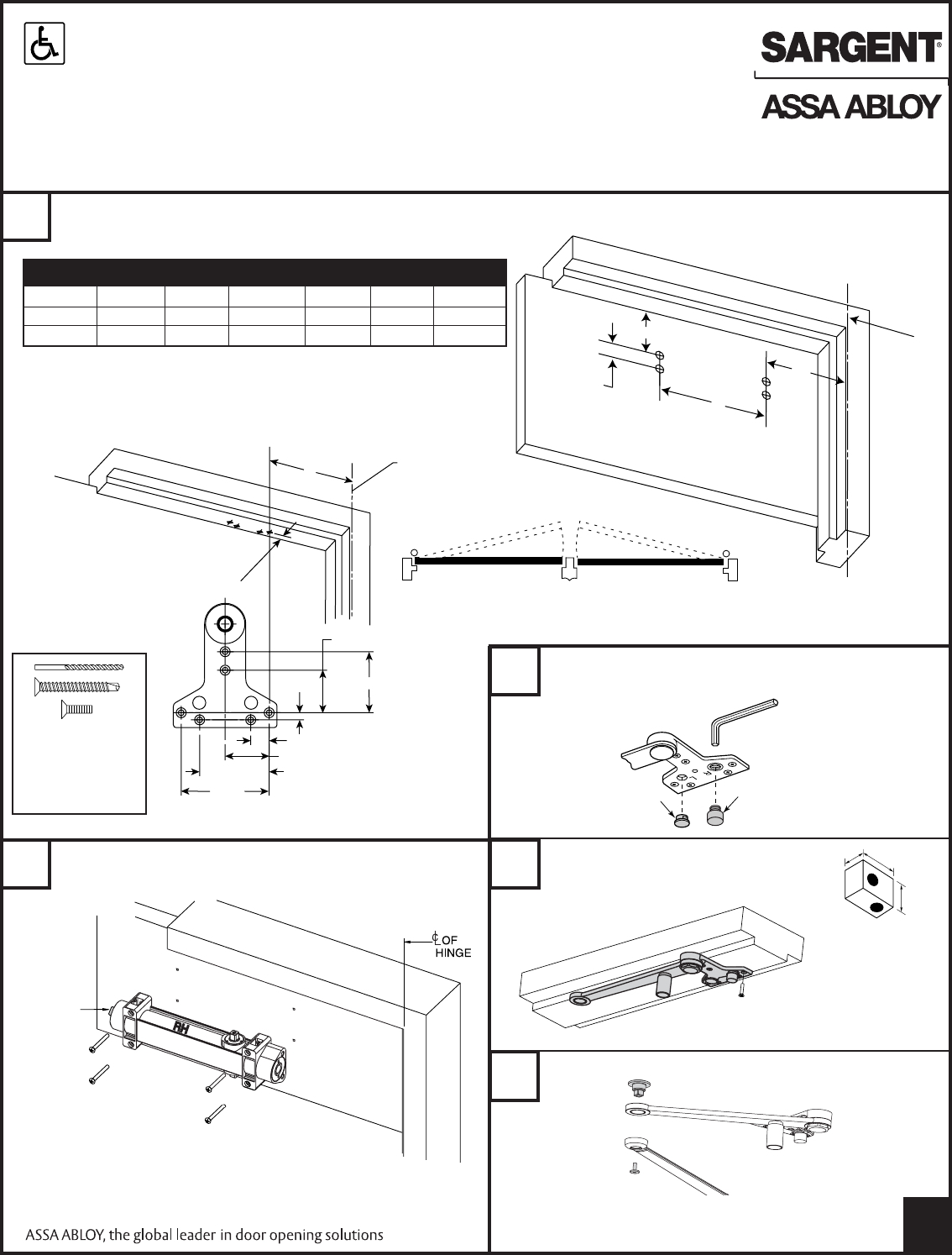
Determine maximum degree of door opening or hold open (PSH) required. Drill and tap door and frame for #12-24
machine screws. When using self-tapping screws provided, predrill with 3/32" drill.
Pull Side Pull Side
Push Side Push Side
Left Hand Door Right Hand Door
Closers are Non-Handed
2Install door closer to door with spring adjustment nut away
from hinge.
RH
SPRING
ADJUSTMENT
NUT
A
13/16"
1-7/8"
2-11/16"
5/16"
13/16"
1-15/16"
3-1/16"
3-7/8"
OF
HINGE
C
L
OF
HINGE
C
L
2-5/8"
9"
B
2-1/2"
(From stop)
Right Hand Door
Shown
NOTE: 351 closer bodies
are non-handed. It is important that the closer body is
installed with “RH” symbol at top for right hand doors,
“LH” symbol at top for left hand doors.
3A Install stop with 1/4" hex wrench to match hand of door.
Turn stop counterclockwise until seated very tight.
1/2" 7/8"
5/8"
PSH arm shown
PS similar
IMPORTANT: USE A MINIMUM OF 5 SCREWS.
Use fifth hole
spacer when
required
Mount foot bracket to door stop.
STOP
PLUG
1/4" HEX
WRENCH
Alternate: Pre-assemble arm prior to attaching to stop.
3B
3C
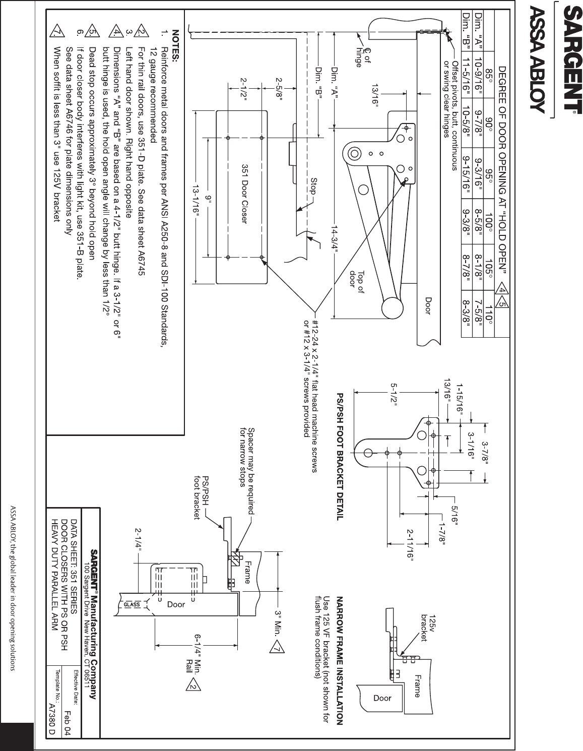
DEGREE OF DOOR OPENING AT “HOLD OPEN” n
85° 90° 95° 100° 105° 110°
DIM. “A” 10-9/16" 9-7/8" 9-3/16" 8-5/8" 8-1/8" 7-5/8"
DIM. “B” 11-5/16" 10-5/8" 9-15/16" 9-3/8" 8-7/8" 8-3/8"
n Dimensions for given degree based on 4-1/2" butts. If 3-1/2" or 6" hinge is
used, hold open angle will change by less than 1/2°.
Dead stop occurs 3° beyond hold open.
IMPORTANT NOTICE
PRE-DRILL 3/32"
HOLES FOR SELF-
TAPPING SCREWS
OR TAP #12-24 FOR
MACHINE SCREWS
+
or
1
A7343G
Copyright © SARGENT Manufacturing. All rights reserved.
Reproduction in whole or in part without the express written
permission of SARGENT Manufacturing is prohibited.
351 Door Closers with PS/PSH Arms
Installation Instructions
351 SERIES ADJUSTABLE FROM SIZE 1 THRU 6
CAUTION: FAILURE TO INSTALL OR ADJUST PROPERLY MAY RESULT IN INJURY OR DAMAGE
For assistance, contact SARGENT at 800-727-5477 or www.sargentlock.com
1
1
2
3
4
5
RH
1
3
4
5
2
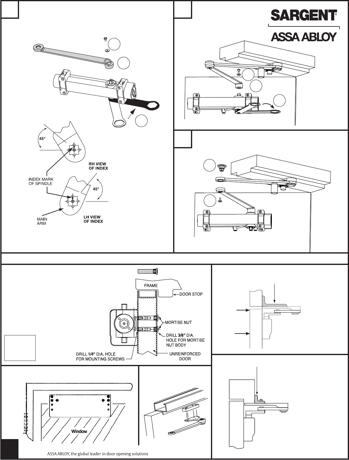
Accessories
125 VF Bracket for flush frame and door condition
OPTIONAL: Use mortise nuts (#4TB)
when through-bolting is required
2
4* A. Rotate bottom spindle 45° with wrench
B. Assemble main arm with index mark
positioned as shown
C. Secure with screw and washer
4A
* WARNING: IF NOT PROPERLY INDEXED, DOOR
CLOSER WILL NOT FUNCTION PROPERLY
!! !!
See Page 1
for
Templating
Dimensions
Flush
frame
Door
A
B
C
Alternate Method:
Attach pre-assembled arm
125 V Bracket for narrow frame condition
351-D Drop Bracket
Used with narrow top rails
D
O
O
R
5A. Open door and install pivot as shown
B. Use screw to secure pivot and arms
Left Hand
Door Opposite
351-D Drop Bracket
581-2 Spacer
Used with blade stops
A
B
C
A
B
A7343G
Copyright © SARGENT Manufacturing. All rights reserved.
Reproduction in whole or in part without the express written
permission of SARGENT Manufacturing is prohibited.
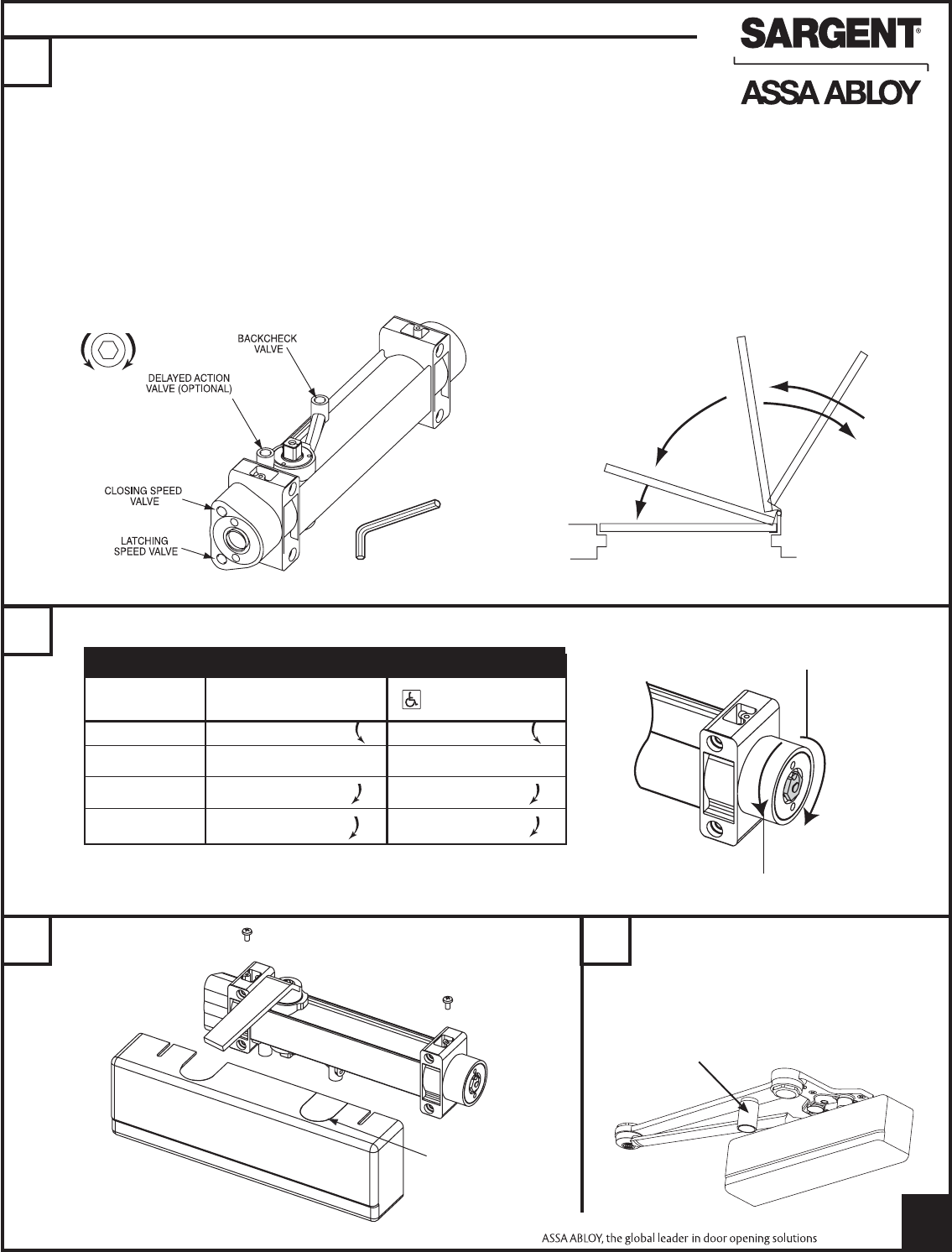
Final Adjustment and Regulating Procedures
6
SLOW
DOWN
SPEED
UP
7Adjust power to allow door to close and latch.
1/8" Hex socket
wrench
Backcheck Range
Delayed Action
Range
Closing Speed
Range
Latching Speed
Range
8Install cover as shown.
3
INSERT IS
REMOVABLE.
PLACE IN
UNUSED OPENING.
Minimum recommended door closing time is 6 seconds for doors opened to 90 degrees.
Use 1/8" Hex (Allen) wrench to adjust valves as needed.*
Closing and latching speeds:
Turn valves clockwise to slow down or counterclockwise to speed up door movement.
Backcheck:
To regulate the intensity of backcheck action turn valve clockwise to increase or
counterclockwise to decrease checking.
CAUTION: SET VALVE FOR SLIGHT CUSHIONING EFFECT. CLOSER CAN BE DAMAGED IF THE CHECKING ACTION IS TOO
ABRUPT. NEVER USE THE BACKCHECK AS A DOOR STOP. ALWAYS USE A DOOR STOP TO STOP THE DOOR.
Delayed Action Feature (optional feature on some models):
“Delayed Action” provides slow door closing through the delayed action range. Turn valve clockwise to slow down or
counterclockwise to speed up door movement.
Adjusting door to close due to high draft conditions may exceed ADA standards.
Consult local ordinances when fire doors are involved.
DOOR WIDTH EXTERIOR DOORS INTERIOR DOORS
(INCHES)
24-30 TURN nut 1-3 TURN nut 1-3
30-36 FACTORY SET FACTORY SET
36-42 TURN nut 1-4 TURN nut 1-3
42-48 TURN nut 7-9 TURN nut 4-6
NUMBER OF TURNS OF SPRING POWER ADJUSTING NUT
Decrease
Increase
To adjust holder arm (PSH only)
All PSH arms are set in hold open at the
factory. To inactivate, turn the adjusting
nut approximately 1-1/2 turns
counter-clockwise.
9
Adjusting nut
* If adjustments are ineffective, check indexing from step 4.
A7343G
Copyright © SARGENT Manufacturing. All rights reserved.
Reproduction in whole or in part without the express written
permission of SARGENT Manufacturing is prohibited.
4
A7343G
Copyright © SARGENT Manufacturing. All rights reserved.
Reproduction in whole or in part without the express written
permission of SARGENT Manufacturing is prohibited.
