Saris Cycling Group SL24TT3 AT3 T Antenna Module User Manual 18562 Layout 1
Saris Cycling Group Inc AT3 T Antenna Module 18562 Layout 1
UserManual.wiki
>
Saris Cycling Group
>
SL24TT3 User Manual
>
User Manual 3
Contents
1.
User Manual 1
2.
User Manual 2
3.
User Manual 3
User Manual 3
Navigation menu
Upload a User Manual
Namespaces
Wiki Guide
HTML
PDF
Info
Views
User Manual
Discussion / Help
Navigation


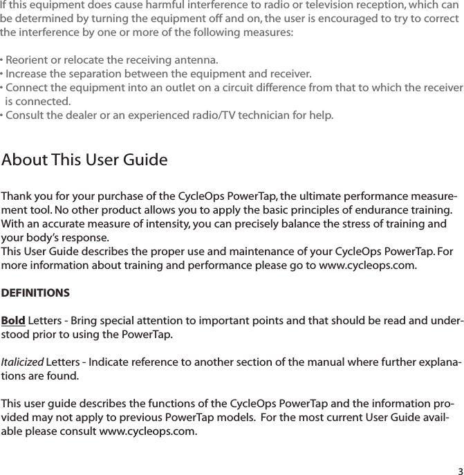


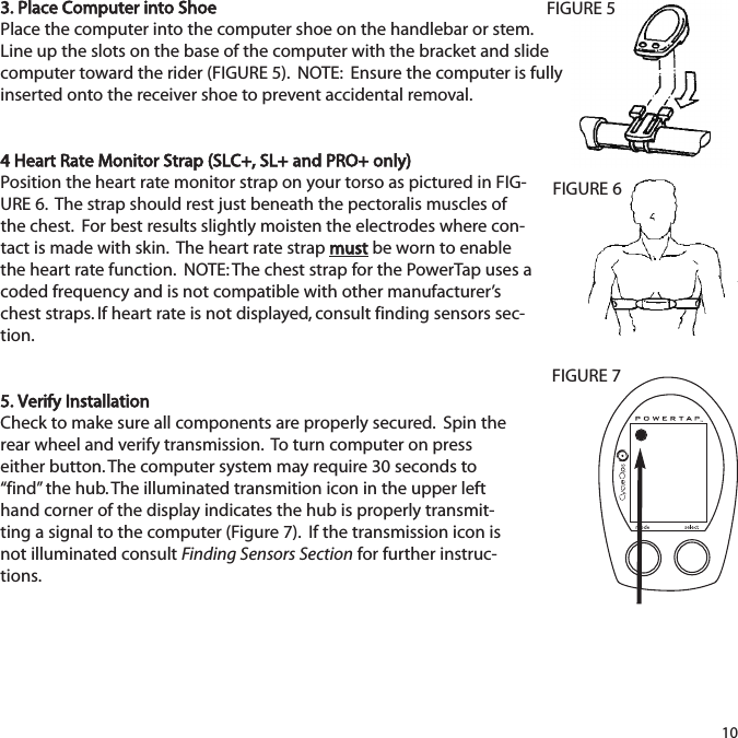
![3652558.I0WATTS3DGeneral Computer OperationDISPLAY LEVELSThe computer has three (3) main display levels:Top Power MiddleSpeed Bottom Multi-Function NOTE: These locations only apply to trip and interval modes and do not apply to Cycle Computer or Heart Rate Monitor Function. See COMPUTER SETUP 4to customize display options. (SLC+, SL+ and Pro+ only)DISPLAY MODESThe computer has two (2) main modes of operation: 1) Trip 2) Interval Hold [MODE] to toggle between display modes.BUTTONSThere are two (2) buttons on the computer:1) [Mode]2) [Select]NOTE: [BRACKETED] words indicate buttons.There are four (4) types of button presses:1) Press [MODE] or [SELECT] - a single press and release of either [MODE] or [SELECT].Used for entering different modes and navigating functionality.11TRANS.ICONINTERVAL DISPLAYMODE (LEFT)POWERDISPLAYSPEED DISPLAYMULTI -FUNCTIONDISPLAYBOTH SELECT (RIGHT)Changes activemode Find hubClear dataEnter setupSelect function](https://usermanual.wiki/Saris-Cycling-Group/SL24TT3.User-Manual-3/User-Guide-1205277-Page-11.png)
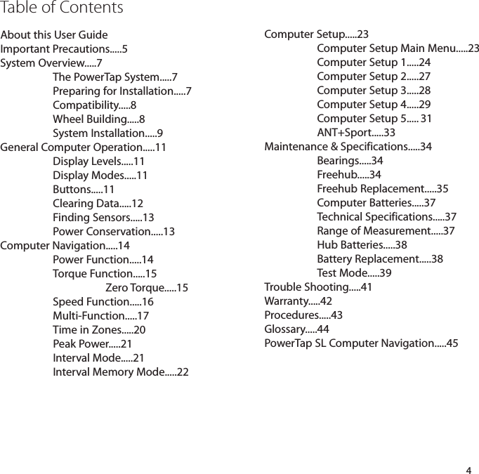
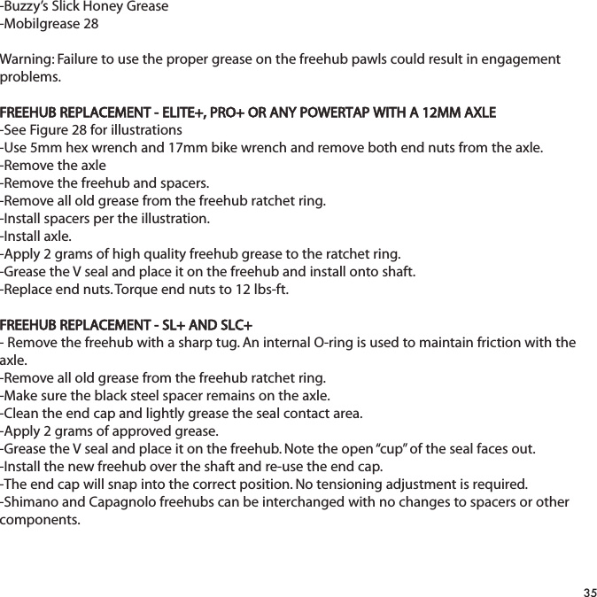
![2) Hold [MODE] or [SELECT] - a single button press and hold of either [MODE] or[SELECT] for 2 sec. Used for initiating a new mode or function.3) Press [MODE] and [SELECT] - simultaneously press and release of both[MODE] and[SELECT]. Used for initiating a new interval.4) Hold [MODE] and [SELECT] - simultaneously press and hold both[MODE] and[SELECT] for 2 sec. NOTE: If mode and select are released when “clr” is displayed, alldata will be erased. Used for initiating scrolling menu.SCROLLING MENU:Note: Only the SLC+, SL+, Pro+ and 2.4+ have setup menus 2, 3, and 4.12SCROLLING MENU:Find: If [MODE] and [SELECT] are releasedWhen “Find” is displayed the computer will findthe PowerTap sensors.clr: If [MODE] and [SELECT] are released whenclr is displayed ALL DATA WILL BE ERASED.SEt: If [MODE] and [SELECT] are releasedWhen SEt is displayed on the top level of the Screen, a flashing “E”, d and t on the middleLevel and 12345 on the bottom level.E= exit, return to ride moded= restore default settingsT= test mode1 2 3 4 5 = setup menus](https://usermanual.wiki/Saris-Cycling-Group/SL24TT3.User-Manual-3/User-Guide-1205277-Page-12.png)
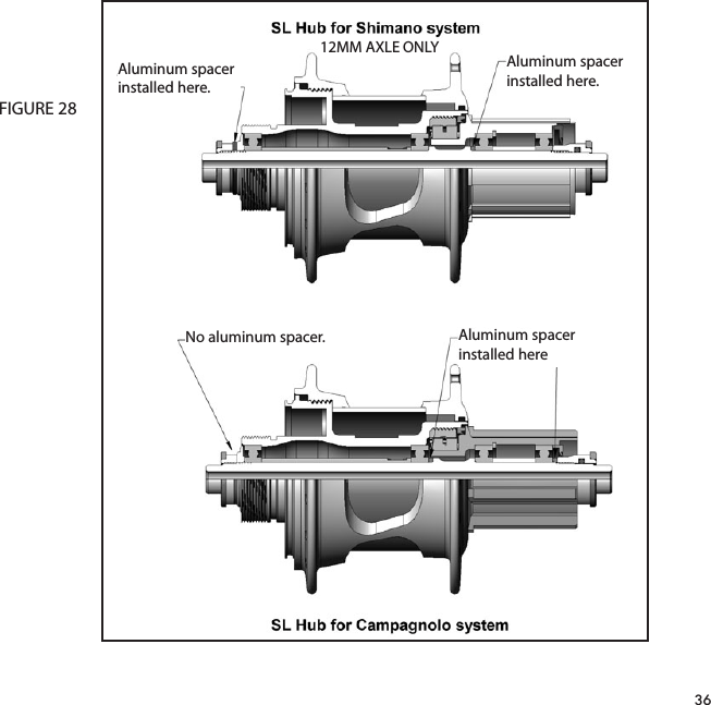
![FINDING SENSORSThe PowerTap hub, sensors and computer are "paired" or "learned" at the factory so that the sys-tem is ready to ride once installed on the bicycle. Learning involves viewing and storing eachdevice ID into the PowerTap computer. Information on learning can be found in computer setup5 section of this owner's manual. In addition, there is a feature called "Find" that allows the user to search for stored devices in theevent a sensor has lost contact with the PowerTap computer for any reason. To initiate the Find,hold [Mode] and [Select]. Release when "Find" appears on the bottom of the PowerTap screenafter about 2 seconds. The current watts display will switch to a spinning dial, indicating thesearch is in process. When the search is successful, the transmission icon appears in the upperleft corner. If device ID's are stored for heart rate and cadence there will be spinning dials forthese metrics as well. POWER CONSERVATIONThe computer and hub have power saving features to prolong battery life. The computer powersdown the display after four (4) minutes of inactivity. Press either [MODE] or [SELECT] to activatethe display. Similarly, the hub powers down after five (5) minutes of inactivity. The transmissionicon will not be visible when the hub is asleep. To wake the hub spin the wheel and verify thetransmission icon is illuminated.13](https://usermanual.wiki/Saris-Cycling-Group/SL24TT3.User-Manual-3/User-Guide-1205277-Page-13.png)
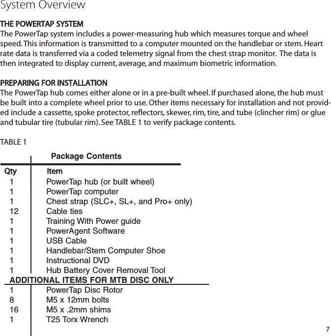
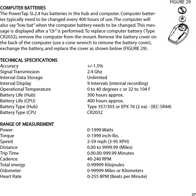
![POWER FUNCTIONThe top level of the main display shows current, max, and average power readings. 1) Press [MODE] to scroll the cursor to the top line of the main display2) Press [SELECT] to toggle through the power function options. For accurate power readings it is important to frequently zero the torque, seeZERO TORQUE.Current PowerPower is displayed in watts from 0-1999 in 1 watt increments. Current powerreadings are displayed only when the word “WATTS” appears below the top line(FIGURE 9). NOTE: If “WATTS” does not appear under the top line the computer isin the Cycle Computer Function. To return to power readings see CYCLECOMPUTER MODE. Maximum PowerBoth “WATTS” and “MX” displayed simultaneously indicate the highest recordedpower output since the last time the data was cleared in trip mode or the selectedinterval in interval mode. (FIGURE 10)Average PowerBoth “WATTS” and “AVG” displayed simultaneously indicate the average power output since the last time the data was cleared in trip mode or the selected interval in interval mode. (FIGURE 11)143652558.I0WATTS3D8492558.I0MX WATTS 3DI952558.I03DAV WATTSFIGURE 9FIGURE 10FIGURE 11Computer NavigationPress [MODE] to scroll through the various functions of the dis-play. Press [SELECT] to toggle through the various optionswithin that funciton. Note: Peak power and Time in Zones infor-mation is only available on the SLC+, SL+, Pro+ and 2.4+ models.MODEbuttonPowerSpeedMulti FunctionPeak PowerTime in ZonesSELECTbuttonMX, AV, WATTSMX, AVD, T, C, E, O, HR:30, 1:00, 5:00, 20:001,2,3](https://usermanual.wiki/Saris-Cycling-Group/SL24TT3.User-Manual-3/User-Guide-1205277-Page-14.png)
![TORQUE FUNCTIONShows the torque placed on the hub in inch-pounds. To display torque while in trip mode:1) Press [MODE] to scroll the cursor to the top line of the main display.2) Press [SELECT] until the current power function is displayed. 3) Hold [SELECT] until the word “WATTS” begins to flash. A blinking “WATTS” display indicates the torque function is currently displayed. 4) Press [SELECT] to return to the current power function. (FIGURE 12).3D0002558.I015FIGURE 12IMPORTANT: ZERO TORQUEFrequently the torque must be zeroed to ensure the most accurate powerinformation is displayed. If the current power display is positive or negative while coasting the the torque mustbe zeroed. This operationmustbe done while stopped with notension on the chain, notensionplaced on the pedals, and the transmission icon must be illuminated. Tozero torque:1) Press [MODE] to scroll the cursor to the top line of the main display.2) Press [SELECT] until current power function is displayed.3) Hold [SELECT] until the word “WATTS” begins to flash to enter thetorque function.4) Hold [SELECT] again until “0” is shown.5) Press [SELECT] to return to current power. The current power functionwill now read zero while coasting.](https://usermanual.wiki/Saris-Cycling-Group/SL24TT3.User-Manual-3/User-Guide-1205277-Page-15.png)
![SPEED FUNCTIONThe middle level of the main display shows current, max, and average speed readings. 1) Press [MODE] to scroll the cursor to the middle line of the main display.2) Press [SELECT] to toggle through the speed function options. Current SpeedSpeed is displayed in either miles per hour (MI) or kilometers per hour (KM) up to59 mi/hr or 95 km/hr in 0.1 mi/hr or km/hr increments. Current speed readingsare displayed when only “MI” or “KM” appears below the middle line. (FIGURE 13)Maximum SpeedEither “MI” or “KM” and “MX” displayed simultaneously indicate the highest record-ed speed since the last time data was cleared in trip mode or the selected intervalin interval mode. (FIGURE 14)Average SpeedEither “MI” or “KM” and “AVG” displayed simultaneously indicate the average recorded speed since the last time data was cleared in trip mode or the selectedinterval in interval mode. (FIGURE 15)163652558.I0WATTS3MID3653358.I0WATTS7MX MID3652058.I03AV MIDWATTSFIGURE 13FIGURE 14FIGURE 15](https://usermanual.wiki/Saris-Cycling-Group/SL24TT3.User-Manual-3/User-Guide-1205277-Page-16.png)
![MULTI-FUNCTION DISPLAYDistance (D)Total trip or the selected interval distance in interval mode is displayed in miles or kilometers from 0.00 to 999.99 (FIGURE 16). 1) Press [MODE] to scroll the cursor to the bottom line of the main display.2) Press [SELECT] to toggle through the multi-function displays until the “D” icon is displayed. NOTE: Distance is displayed in the same units (miles vs kilometers) as speed. Trip Time and Time of Day (T)Total trip time, interval time, and time of day is displayed as H.MM.SS for trip timeand HH:MM for real time (FIGURE 17). 1) Press [MODE] to scroll the cursor to the bottom line of the main display.2) Press [SELECT] to toggle through the multi-function displays until the “T” icon is displayed. 3) While in trip time hold [SELECT] to access the real time clock. 4) Hold [SELECT] to return to trip or interval time. NOTE: Auto start and stop with rotation of the wheel is the default setting. To customize autostart and stop see COMPUTER STETUP 4. 3652558.I0WATTS3MI365252.5 I.43WATTS3MIT DFIGURE 16FIGURE 1717](https://usermanual.wiki/Saris-Cycling-Group/SL24TT3.User-Manual-3/User-Guide-1205277-Page-17.png)
![Cadence (C)Cadence is measured at the hub by analyzing the way a rider applies torquethrough the pedal stroke since there are natural power differences in the pedalstroke. The rate of pedaling is shown from 40 to 240 RPM. NOTE: An optional wireless cadence sensor is available to measure cadence atthe crank.1) Press [MODE] to scroll the cursor to the bottom line of the main display.2) Press [SELECT] to toggle through the multi-function displays until the "C" icon is displayed.(FIGURE 18)183652589WATTS3CFIGURE 18](https://usermanual.wiki/Saris-Cycling-Group/SL24TT3.User-Manual-3/User-Guide-1205277-Page-18.png)
![Average Cadence (C & AVG)The average cadence displays data since the last time data was cleared in tripmode or the selected interval in interval mode. Average cadence is displayed inRPM. 1) Press [MODE] to scroll the cursor to the bottom line of the main display.2) Press [SELECT] to toggle through the multi-function displays until the “C” and“AVG” are displayed. (FIGURE 19)Energy Expenditure (E)The total work done over the course of the trip or interval is shown in kilojoules.This value is a measure of the total energy expended over the course of your ride.This is roughly equivalent to dietary calories expended.1) Press [MODE] to scroll the cursor to the bottom line of the main display.2) Press [SELECT] to toggle through the multi-function displays until the “E” is dis-played. (FIGURE 20)Odometer (O)Total accumulated distance traveled since the last system reset is displayed inmiles or kilometers. To manually input the your odometer reading see COMPUTERSETUP 1. 1) Press [MODE] to scroll the cursor to the bottom line of the main display.2) Press [SELECT] to toggle through the multi-function displays until the “O” is displayed. (FIGURE 21)193652576WATTS3C AV365252009WATTS3E365252584WATTS3OFIGURE 19FIGURE 20FIGURE 21](https://usermanual.wiki/Saris-Cycling-Group/SL24TT3.User-Manual-3/User-Guide-1205277-Page-19.png)
![Heart Rate ( )Current heart rate is shown up to 255 beats per minute (BMP). You must wear theheart rate chest strap to enable the heart rate measurement function. NOTE: ThePowerTap uses a coded chest strap. Elite + users must purchase an ANT+ compat-ible chest strap for this function to operate.1) Press [MODE] to scroll the cursor to the bottom line of the main display.2) Press [SELECT] to toggle through the multi-function displays until the “ ” isdisplayed. (FIGURE 22)Average Heart Rate ( AV)This value is a running average of the heart rate in BPM. If there is no heart rateinformation this will display as 0. 1) Press [MODE] to scroll the cursor to the bottom line of the main display.2) Press [SELECT] to toggle through the multi-function displays until the “ AV” isdisplayed. (FIGURE 25)TIME IN ZONES (SLC+, SL+, PRO+ AND 2.4+ ONLY)Time in Zones displays the amount of time spent above, below or at your lacticthreshold. The default lactic threshold is 250 watts, but can be modified throughSetup 1. +/-10% from the value is considered at the threshold.1) Press [MODE] to scroll the cursor until the top line shows 2on. 2) Press [SELECT] to toggle through the 3 zones.Zone 1 - Below ThresholdZone 2 - At ThresholdZone 3 - Above Threshold2036525I72WATTS 3FIGURE 22FIGURE 2436525I72WATTS 3AVFIGURE 232on37:44WATTSMIT](https://usermanual.wiki/Saris-Cycling-Group/SL24TT3.User-Manual-3/User-Guide-1205277-Page-20.png)
![PEAK POWER (SLC+, SL+, PRO+ AND 2.4+ ONLY)Peak power displays your maximum average power for various time intervals.1) Press [MODE] to scroll the cursor until the middle line shows PP. 2) Press [SELECT] to toggle through the different time intervals0:30, 1:00, 5:00 and 20:00.INTERVAL MODEThe computer has two display modes. The trip mode shows total trip metrics, and the interval mode displays interval specific information. The interval mode functions as a lap marker and is essentially always on. To begin the first interval, or advance to the next interval:Press and release[MODE] and [SELECT] simultaneously. NOTE: Do nothold both buttons down as you may clear all data from the comput-er. In trip mode “INT” and the new interval number will appear and disappear (FIGURE26). The computer can mark an unlimited number of intervals although after nine(9) the marker will begin to count back at one (1). For example, interval ten (10) isdisplayed following interval (9) as one (1). To view interval specific data (power, speed, and multi-function display) from anylocation on the display:1) Hold [MODE] until “INT” appears on the left hand side of the display. The “INT”and interval number will remain illumined as a forth line in the main display (FIG-URE 24). The data displayed is that of the current interval number shown. 2)To exit back out of interval mode hold [MODE] until “INT” disappears.213651152WATTS 3MIAVFIGURE 26intFIGURE 25400pp20:00MX WATTST](https://usermanual.wiki/Saris-Cycling-Group/SL24TT3.User-Manual-3/User-Guide-1205277-Page-21.png)
![INTERVAL MEMORY MODETo access stored interval data for the previous 9 intervals only: 1) Enter the interval mode hold [MODE] until “INT” appears on the left hand side of the display.2) Press [MODE] to scroll until the “INT” flashes. NOTE: INT now constitutes a fourth level of dis-play.3) Hold [SELECT] and the memory icon (”M”) appears next to the interval number (FIGURE 27). 4) With “INT” flashing, press [SELECT] to advance to the interval you wish to view. 5) Press [MODE] scroll the cursor to the line of information you wish to view. NOTE: Recoveryperiods as well as work periods are displayed in memory mode.To exit back out of the interval memory mode hold [SELECT] until the memory icon disappears.The computer is now displayed in the interval mode. To exit from the interval mode from anylocation on the display hold [MODE] until “INT” disappears.Note: Time in Zone information is not available in Interval Memory Mode. Download the data into PowerAgent for a detailed analysis.22INT2FIGURE 27](https://usermanual.wiki/Saris-Cycling-Group/SL24TT3.User-Manual-3/User-Guide-1205277-Page-22.png)
![Computer SetupThe setup feature has five(5) main modes. You do not have tocomplete all five to change settings. Please reference each modeto determine the correct location to begin. NOTE: The computerillustrations for each mode displays the factory default settings.COMPUTER SETUP MAIN MENU1) Press either [MODE] or [SELECT] to activate the computer. NOTE: The version of firmware is displayed upon startup. Themost updated firmware version is available at www.cycleops.com.(FIGURE 28)2) Extended hold of [MODE] and [SELECT] simultaneously enterscomputer setup function. NOTE: Continue to hold through “clr”screen. Releasing hold early will clear all current data.3) The setup mode displays three (3) letters and numbers 1-5.Each letter represents a setup menu. A flashing alphanumericcharacter indicates current selection. (FIGURE 29)E = exit, return to ride moded = restore default settings T = test mode 1 2 3 4 5= setup menusNote: Only the SLC+, SL+, Pro+ and 2.4+ have setup menus 2, 3and 4.4) Press [SELECT] to scroll to the desired setup mode.5) Press [MODE] to begin setup.23Set12345FIGURE 29Pro5.33FIGURE 28EtdNote: The new pro-duction version willmark 6.0 version offirmware.](https://usermanual.wiki/Saris-Cycling-Group/SL24TT3.User-Manual-3/User-Guide-1205277-Page-23.png)
![COMPUTER SETUP 1This setup menu includes: time of day, date, storage rate, wheel circumference, units of measure,odometer and lactic threshold. NOTE: You are unable to move back to previously viewed set-tings. You must restart setup 1 to make corrections. You may hold [MODE] and [SELECT] to saveand exit setup.1) From the computer setup main menu press [SELECT] and scroll until thenumber one (1) is flashing. Press [MODE] to enter setup mode.2) Press [SELECT] to toggle between a 12 or 24 hour clock. Press [MODE] tosave.3) Press [SELECT] to toggle between AM (A) or PM (P). Press [MODE] tosave.4) Press [SELECT] to toggle through digit values to set hours in time of day.Press [MODE] to save. 24Stdt12StdtStdpt12:00pSetE12345td](https://usermanual.wiki/Saris-Cycling-Group/SL24TT3.User-Manual-3/User-Guide-1205277-Page-24.png)
![5) Press [SELECT] to toggle through digit values to set minutes in time ofday. Press [MODE] to save.6) Press [SELECT] to toggle through digit values to set year, month, anddate. Press [MODE] to save.7) Press [SELECT] to toggle through storage rate values (1, 2 seconds).Press [MODE] to save. NOTE: Different storage rates yield different amountsof total storage time. Changes to the storage rate do not effect displayinformation. Refer to TABLE 3 for appropriate storage rate. TABLE 3 - PowerTap Storage Rate8) Press [SELECT] to toggle through digit values to set the wheel circumfer-ence. Press [MODE] to save. Refer to TABLE 4 for common tire information.NOTE: For the most accurate reading perform a roll out measurement(mm) of the rear wheel.25Std0301-01cYearDayMonthStdrec1Std1CIr2096Recording Rate (sec)SLC+, SL+, Pro+ and 2.4+ (hrs)Elite + (hrs)1 sec.12 62 sec.24 12](https://usermanual.wiki/Saris-Cycling-Group/SL24TT3.User-Manual-3/User-Guide-1205277-Page-25.png)
![TABLE 4 - Common Wheel Circumferences9) Press [SELECT] to toggle between English or Metric units. Press [MODE] to save.10) Press [SELECT] to set starting odometer reading. Press [MODE] to save.NOTE: Odometer settings are saved during battery changes.26Std1Std100000ODomi](https://usermanual.wiki/Saris-Cycling-Group/SL24TT3.User-Manual-3/User-Guide-1205277-Page-26.png)
![COMPUTER SETUP 2 (SLC+, SL+, Pro+ and 2.4+ only)This setup menu includes: rate of display for watts, speed, and cadence. NOTE: You are unable tomove back to previously viewed settings. You must restart setup 2 to make corrections. NOTE:These settings do not effect the data stored for download. This function can be used to allow better pacing during time trial efforts. A greater rate of dis-play allows for a slower update of the display.1) From the computer setup main menu press [SELECT] and scroll until thenumber two (2) is flashing and press [MODE] to enter setup mode.2) Press [SELECT] to toggle through (1, 2, 3, 5 10, 30) rate of display values inseconds for watts. Press [MODE] to save. 3) Press [SELECT] to toggle between (1, 2, 3, 5 10, 30) rate of display valuesin seconds for speed. Press [MODE] to save. 4) Press [SELECT] to toggle between (1, 2, 3, 5 10, 30) rate of display valuesin seconds for cadence. Press [MODE] to save. 6) Press [SELECT] then [MODE] to reset default settings. Press [MODE] tosave changes.27PRO22AV WATTSPRO23AV MIPRO25C AV SetE12345td](https://usermanual.wiki/Saris-Cycling-Group/SL24TT3.User-Manual-3/User-Guide-1205277-Page-27.png)
![COMPUTER SETUP 3This setup menu includes: zero readings for power, speed, and cadence. NOTE: You are unable tomove back to a previously viewed setting. You must restart setup 3 to make corrections. NOTE:These settings are useful for determining you average power reading when pedaling only and donot effect the data that is stored for download. 1) From the computer setup main menu press [SELECT] and scroll until thenumber three (3) is flashing and press [MODE] to enter setup mode.2) Press [SELECT] to toggle between yes and no for zeros included in aver-age of watts. Press [MODE] to save. 3) Press [SELECT] to toggle between yes and no for zeros included in aver-age of speed. Press [MODE] to save. 4) Press [SELECT] to toggle between yes and no for zeros included in aver-age of cadence. Press [MODE] to save. 5) Press [SELECT] to toggle between yes and no for auto-zero function.Normally leave at yes. NOTE: Auto-zero ‘NO’ is used for track bike use wherelarge negative torque may be present. Hub modification to fixed gear isnecessary.28PRO30’sYESAV WATTSPRO0’sAV MIYESPRO3c av0’sYESPRO3tYESSetE12345td](https://usermanual.wiki/Saris-Cycling-Group/SL24TT3.User-Manual-3/User-Guide-1205277-Page-28.png)
![COMPUTER SETUP 4This setup menu includes: sleep time, locations of display, cadence source, cycle computer mode,heart rate monitor, and auto start/stop. From this menu you are unable to move back to previ-ously viewed settings. You must restart setup 4 to make corrections. 1) From the computer setup main menu press [SELECT] and scroll until thenumber four (4) is flashing and press [MODE] to enter setup mode.2) Press [SELECT] to set how many minutes the computer will stay “awake”after not receiving a valid speed or heart rate signal. Press [MODE] to save.NOTE: The shorter the sleep time the longer the battery life.3) Press [SELECT] to determine what is displayed in the middle line. (mi =speed, c = cadence, ( ) = heart rate). Press [MODE] to save. The selectedmetric will flash during the ride. NOTE: If heart rate or cadence is selectedspeed is not displayed. This is useful for intervals when power, heart rateand cadence are most important.4) Press [SELECT] to determine cadence information source. Default = pedal then hubPedal = crank onlyHub = hub onlyNOTE: An optional cadence sensor is available (sold separately).Press [MODE] to save.29PRO44SLEEPPRO4miPRO4pedalcHuPSetE12345td](https://usermanual.wiki/Saris-Cycling-Group/SL24TT3.User-Manual-3/User-Guide-1205277-Page-29.png)
![5) The PowerTap can be used as a cycle computer or heart rate monitor.Press [SELECT] to toggle through mode options. watts, mi, and ( ) = power meter modemi, and ( ) = cycle computer mode ( ) = heart rate monitor modePress [MODE] to save.6) Press [SELECT] to toggle through auto start options. mi, and data = allows trip time to count when wheel speed is registering.Trip time stops 3 sec. after if speed is not registered.( ), and data = allows trip time to count as long as a heart rate signal isregistered. This function is useful in the transition from cycling to runningand vice versa.7) Press [SELECT] to start setting the lactic threshold. The default value is250W. Press [SELECT] to toggle through the digit values to set the lacticthreshold. Press [MODE] to advance to the next digit. After the last digit isset, press [MODE] to save.30PRO4miwattsPRO4miwattsdataCYCLE COMPUTER MODEThis funtion allows the PowerTap computer to function as a cycle computer in theabsence of the PowerTap hub. In Cycle Computer Mode heart rate is displayed in thetop line of the main display and power data is no longer displayed. Speed, distance,odometer and time are displayed normally.(Speed sensor sold separately)HEART RATE MONITOR MODEThis function allows the PowerTap computer to function as a heart rate monitor inthe absence of the PowerTap hub. In Heart Rate Monitor Mode heart rate is displayedon the top line of the main display and power data is no longer displayed.Ltwatts0250](https://usermanual.wiki/Saris-Cycling-Group/SL24TT3.User-Manual-3/User-Guide-1205277-Page-30.png)
![COMPUTER SETUP 5This setup allows the CPU to learn a new device or sensor such as the hub, heart rate strap andoptional cadence sensor. NOTE: This process only needs to be used if a new sensor or hub isbeing used in conjunction with your CPU or vice versa. There are 2 Learn sequences, 1 and 2.Learn 1 is used when you have switched sensors or the CPU and there are no other like bikeswith PowerTap within a 30’ radius. Learn 2 is used if there are other devices in the area butrequires you to remove and reinsert the battery for that device before activating the Learn 2sequence.1) From the computer setup main menu press [SELECT] and scroll until the number five (5) is flashing and press [MODE] to enter setup mode.2) Press [SELECT] to toggle through the digit values to set the Hub ID. Press [MODE] to advance to the next digit. After the last digit is set, press [MODE] to save.Note: Use either Learn 1 or Learn 2 to set the hub ID when the numberical value is not known. (Most cases) Make sure the hub is awake byspinning the wheel or axel. 3) Initiate Learn 1 by holding [SELECT] until “Learn” begins to flash. Learn 1 will search for any active hub so be sure there are no other nativehubs in the area. When the search is complete press [MODE] to advance to Learn 2.Note: If Learn 1 was successful, learn 2 is not necessary.4) Initiate Learn 2 by first removing the batteries from the hub for 5 seconds and replacing them. Then hold [Select] until "Learn" begins to flash. When the CPU has learned the hub I.D. it will display the I.D. Press [Mode] to save and proceed to the next device I.D. If it did not learn the device it will take you back to the most recent Hub I.D. 31hubId45847hubIdLEArn1hubIdLEArn1flashinghubIdLEArn2hubIdLEArn2flashingSetE12345td](https://usermanual.wiki/Saris-Cycling-Group/SL24TT3.User-Manual-3/User-Guide-1205277-Page-31.png)
![5) Follow the above steps for any additional sensors you may be using, such as the heart rate strap, speed and cadence sensors. The sensor name isshown on the top line of the display.SPd = speed sensorCd = cadence sensorHS = heart rate sensorPress [SELECT] to toggle through the digit values to get the I.D. Press [MODE] to advance to the next digit. When the last digit is set, press [MODE] to save and advance to the learn functions for that sensor. Press [SELECT] to initiate the learn functions as needed.Note: Changing the batteries in the speed sensor, cadence sensor or heartrate sensor creates a new ID for that device. If other computers are pairedusing the old ID, they will need to re-learn the sensor.32SPdCdHS](https://usermanual.wiki/Saris-Cycling-Group/SL24TT3.User-Manual-3/User-Guide-1205277-Page-32.png)


![-Slide the battery pack back into position along the center core. As the pack is engaged a small increase of resistance to installation should be felt as the electrical connections are made.- Thread the cap all the way back on.- Replacement O-rings and battery packs are available from Saris Cycling Group.TEST MODE1) From the computer setup main menu press [SELECT] and scroll until the letter “t” is flashing. Press [MODE] to enter test mode setup.2) Press [MODE] to scroll through the different test modes as shown by the number. NOTE: Press and hold [MODE] and [SELECT] simultaneously returns to standard operation.0 - Model and version.Displays the computer model on the middle line and firmware version number on the bottomline.1 - LCD TestDisplays all the LCD segments. Press [SELECT] to return to the normal screen.2 - Heart Rate Signal TestNOTE: The heart rate signal is illuminated.The middle line display flashes “88” with each heart rate blip received.3- Torque Information NOTE: The T icon is displayed.This displays information about the internal workings of the torque readings. The bottom displayis the offset torque value directly sent by the hub torque with no correction applied. The hubsends a value of approximately 512 as the zero point. The middle line display is the correctionoffset value currently stored in the computer. This is the value that is changed when you do amanual zeroing of the torque. The top display is the corrected actual torque (the bottom valueminus the middle value).39](https://usermanual.wiki/Saris-Cycling-Group/SL24TT3.User-Manual-3/User-Guide-1205277-Page-39.png)
![4 - Standard Test FileThis mode writes a small test file to the memory. Press [SELECT] and the bottom lines says “run”and then “yes” when the file is written. This file can then be downloaded.5 - Communication Loop Back TestWhen looking at the front side of the computer, use a coin or paper clip to short out the two pinson the left side. Press [SELECT]. The bottom line will say “run” and then “yes” if it passes the testcorrectly. If the pins are not shorted together or there was a problem, the display will say “no”. Thistest can be repeated by pressing [SELECT].6 - Fast Memory TestThis tests the memory in the computer. Press [SELECT] and “run” is displayed on the bottom line.When the test is completed and it passes, it says “yes”. If the test should fail, the bottom line willsay “no”.40](https://usermanual.wiki/Saris-Cycling-Group/SL24TT3.User-Manual-3/User-Guide-1205277-Page-40.png)
![TroubleshootingNo display on computer screen· Computer is asleep – Press [MODE] or [SELECT] on the computer to wake up the computer.· Batteries need replacement - replace the computer batteries as shown in the maintenance section of the User Manual.· Computer is too cold- operating temp. is 32 to 110 degrees FahrenheitComputer display is on, but there is no transmission icon· Hub is asleep - spin the wheel to wake up the hub.· Computer has not “found” the hub. Press and hold [MODE] and [SELECT] until “Find” appears on the display. Make sure hub is awake by rotating wheel once.· Batteries need replacement - replace the hub batteries as shown in the maintenance section of the User Manual.· Does the word “watts” appear under the top line? If no than you have entered cycle computer mode. See cycle computer mode for further instructions.· Interference with other devices - make sure you are not setting up the PowerTap inside a building with a lot of electrical noise, neon signs, or near power lines. Bring the PowerTap outside or away from the electrical disturbance to see if signal returns. Also make sure you don’t have any other devices on your bike such as lights, magnets or cycle computer sensors.· PowerTap computer’s batteries are low, replace batteries as shown in the maintenance section of the User Manual. We recommend using a Cone Wrench to remove the battery cap, not a coin.Displayed data blinks or does not function· Batteries need replacement - replace the computer batteries as shown in the maintenance section of the User Manual. · Interference with other devices - make sure you are not setting up the PowerTap inside a building with a lot of electrical noise, neon signs, or near power lines. Bring the PowerTap outside or away from the electrical disturbance to see if signal returns. Also make sure you don’t have any other devices on your bike such as lights, magnets or cycle computer sensors.Power seems incorrect·Torque value is not zeroed. To manually zero torque, go to current watts and hold down the 41](https://usermanual.wiki/Saris-Cycling-Group/SL24TT3.User-Manual-3/User-Guide-1205277-Page-41.png)
![[SELECT] button until watts disappears. Torque is now being displayed. To zero torque hold down the [SELECT] button until the value reads zero. To exit torque mode press [SELECT] once. If re-zeroing the torque does not recalibrate the unit, call Saris Cycling Group customer service at 1-800-783-7257.Speed seems incorrect· Wheel size incorrect -refer to setup 1 and enter the correct size in setup mode.Transmission icon flashes rapidly· Hub batteries need replacement - replace the hub batteries as shown in the maintenance section of the User Manual.WarrantyCycleOps PowerTap is warranted to the original retail purchaser to be free from defects in materi-als and workmanship. Warranty coverage is valid to the original purchaser only and proof of pur-chase will be required.Electronics - 1 yearThis warranty does not cover:1. Normal wear and tear.2. Any damage, failure or loss caused by accident, misuse, neglect, abuse, improper assembly,improper maintenance, or failure to follow instructions or warnings in Owner’s Manual.3. Use of products in a manner or environment for which they were not designed.LimitationsThe foregoing warranties are in lieu of and exclude all other warranties not expressly set forthherein, whether expressed or implied by operation of law or otherwise, including, but not limitedto, warranties of merchantability or fitness for a particular purpose. Saris Cycling Group shall inno event be liable for incidental or consequential losses, damages or expenses in connection42](https://usermanual.wiki/Saris-Cycling-Group/SL24TT3.User-Manual-3/User-Guide-1205277-Page-42.png)
![GlossaryComputer - Refers to the yellow handlebar or stem mounted device.Heart Rate (HR)- This displays current HR. Max and average values are displayed if [MAX] or[AVG] is selected. Watts- Real-time display of the effort you are putting in to pedaling the bike. This is your powerreading. **If you press the [SELECT] while the cursor is pointing to Watts the line changes to"inch-lbs". This is the raw torque value that is being applied to the hub, NOT your power in watts. Cadence (C) - The number of pedal revolutions per minute. The rate of pedaling is shown from 0to 140 RPM.Speed - The rate that you are traveling.Scroll = To move vertically through available menu or screen optionsToggle = To move horizontally through alphanumeric digitsCursor = The ® arrow located on console screenMetrics = a standard of measurementMAX = MaximumRPM = Revolutions Per MinuteMI = Miles indicates Miles Per HourKM = Kilometers indicates Kilometers Per HourUI = User Interface44](https://usermanual.wiki/Saris-Cycling-Group/SL24TT3.User-Manual-3/User-Guide-1205277-Page-44.png)
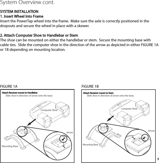
![45Saris Cycling Group, Inc.5253 Verona RoadMadison, WI. 537111-800-783-725718562 09/08Patents issued and pending.Patent#6,418,797POWERTAP SL COMPUTER NAVIGATIONMAIN MENUINTERVAL MODEINTERVAL MEMORY MODEMiddle DisplayCurrent SpeedMax SpeedAverage SpeedTop DisplayCurrent PowerMax PowerAverage PowerBottom DisplayDistanceTrip TimeCadenceAverage CadenceEnergy ExpenditureOdometerHeart RateAverage Heart RateTime of dayHold [SELECT]Hold [SELECT]TorqueFunctionPress [SELECT]Press [SELECT]Press [MODE]Press [MODE]Press [SELECT]Press [SELECT]Press [SELECT ]Press [SELECT]Press [MODE]Press [SELECT]Press [SELECT]Press [SELECT]Press [SELECT]Press [SELECT]Press [SELECT]Press [MODE]Hold [SELECT]Hold [MODE]Press [SELECT]Peak Power:301:005:0020:00Time In Zones123Press [SELECT]Press [SELECT]Press [SELECT]Press [SELECT]Press [SELECT]](https://usermanual.wiki/Saris-Cycling-Group/SL24TT3.User-Manual-3/User-Guide-1205277-Page-45.png)