Satel SATEL-TA31 Radio Modem Module User Manual 3AS User Guide
Satel Oy Radio Modem Module 3AS User Guide
UserManual.wiki
>
Satel
>
SATEL TA31 User Manual
Integration Manual
Navigation menu
Upload a User Manual
Namespaces
Wiki Guide
HTML
PDF
Info
Views
User Manual
Discussion / Help
Navigation

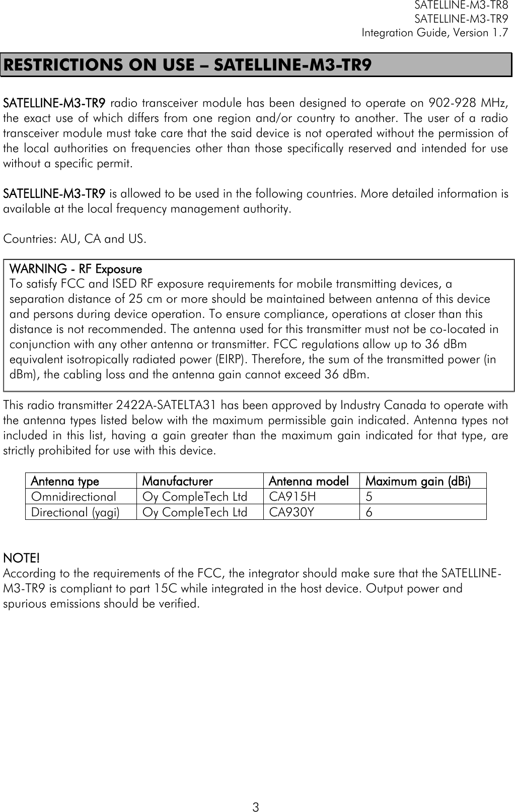
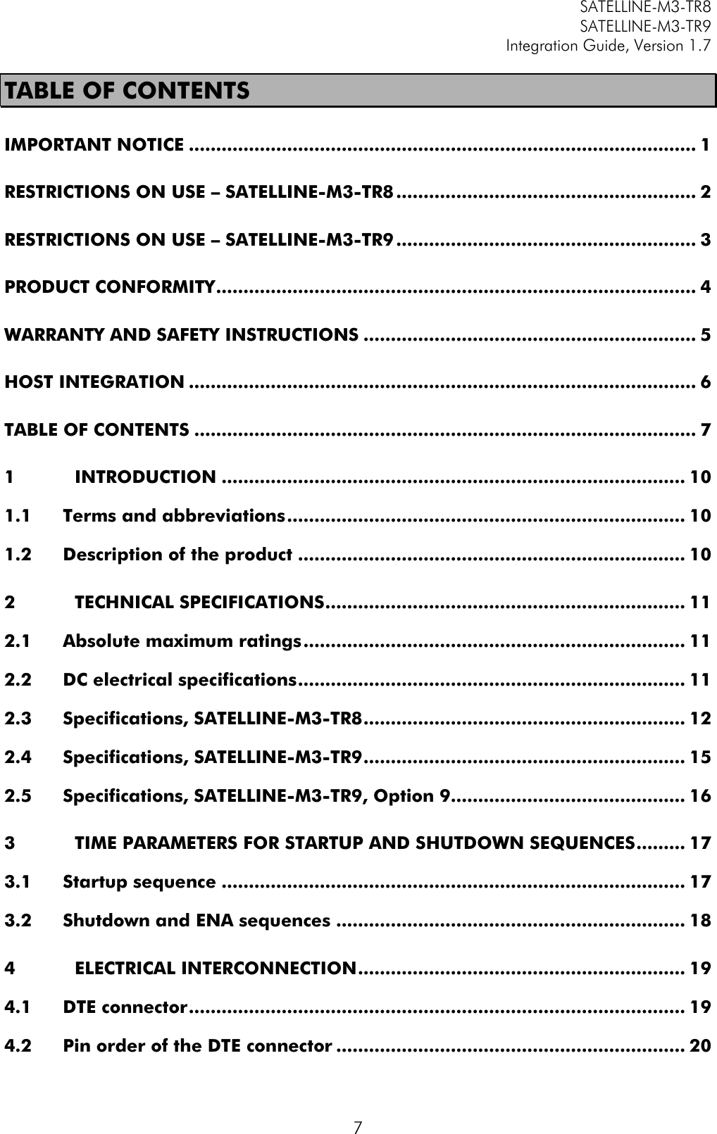
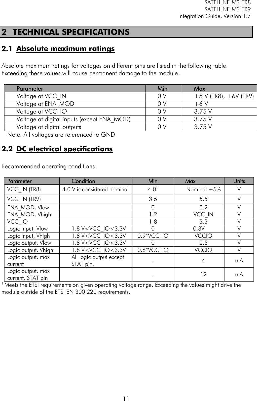
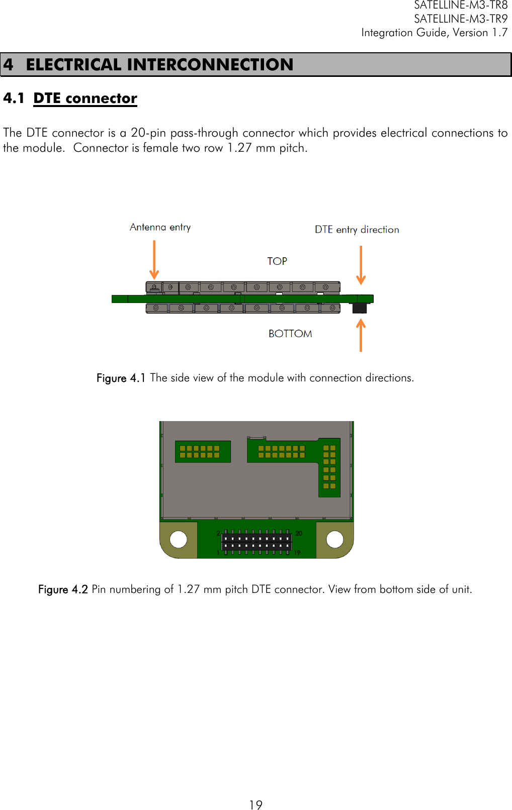
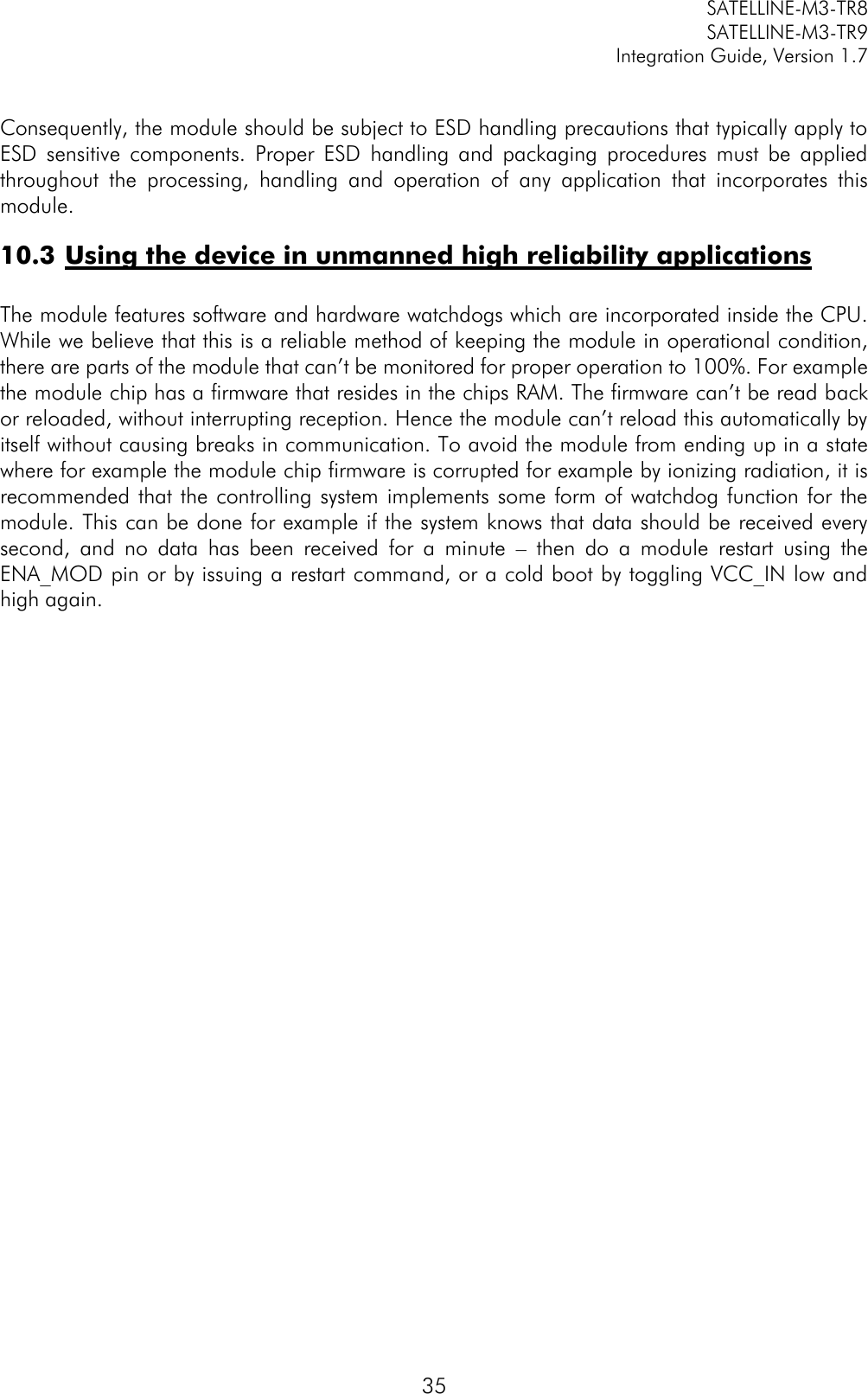
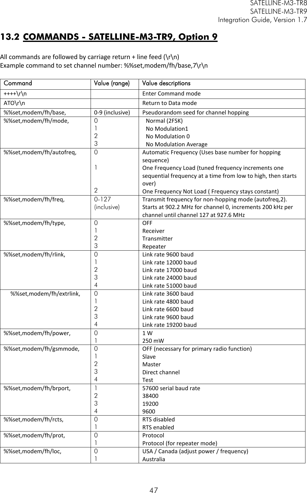
![SATELLINE-M3-TR8 SATELLINE-M3-TR9 Integration Guide, Version 1.7 37 12 APPENDIX B 12.1 SL COMMANDS – SATELLINE-M3-TR8 Category Command Description Response Addressing SL#A? Show all addresses (RX1, RX2, TX1, TX2) "xxxx,yyyy,zzzz,vvvv" Addressing SL#A=xxxx, yyyy, zzzz,vvvv Set RX/TX addresses (RX1, RX2, TX1, TX2) “OK" or "ERROR" Addressing SL#I? Get primary addresses (TX1, RX1) "xxxx;yyyy" Addressing SL#I=xxxx Set all addresses (RX1, RX2, TX1, TX2) to value xxxx [0000....ffff] “OK" or "ERROR" Addressing SL#P? Get primary transmit address (TX1) and primary receive address (RX1) "xxxx;yyyy" Addressing SL#P=xxxx;yyyy Set primary transmit address (TX1) to value xxxx and primary receive address (RX1) to value yyyy [0000....ffff] “OK" or "ERROR" Addressing SL#Q? Get TX address mode "0" = TX address OFF "1" = TX address ON Addressing SL#Q=x Set TX address ON/OFF. Values of x are: "0" = TX address OFF "1" = TX address ON “OK" or "ERROR" Addressing SL#R? Get primary receive address (RX1) "yyyy" Addressing SL#R=xxxx Set receive addresses (RX1, RX2) to value xxxx [0000....ffff] “OK" or "ERROR" Addressing SL#S? Get secondary transmit address (TX2) and secondary receive address (RX2) "xxxx;yyyy" Addressing SL#S=xxxx;yyyy Set secondary transmit address (TX2) to value xxxx and secondary receive address (RX2) to value yyyy [0000....ffff] “OK" or "ERROR" Addressing SL#T? Get primary transmit address (TX1) "xxxx" Addressing SL#T=xxxx Set transmit addresses (TX1, TX2) to value xxxx [0000....ffff] “OK" or "ERROR" Addressing SL#W? Get RX address mode "0" = RX address OFF "1" = RX address ON Addressing SL#W=x Set RX address ON/OFF. Values of x are: "0" = RX address OFF "1" = RX address ON “OK" or "ERROR" ChannelList SL$A=1 Go to channel list default channel “OK" or "ERROR" ChannelList SL$C? Get number of channels in channel list decimal number ChannelList SL$C=nn Set number of channels in channel list. nn = 0...40, 0 clears the whole list “OK" or "ERROR" ChannelList SL$D? Get channel list default channel number decimal number](https://usermanual.wiki/Satel/SATEL-TA31/User-Guide-3580287-Page-38.png)
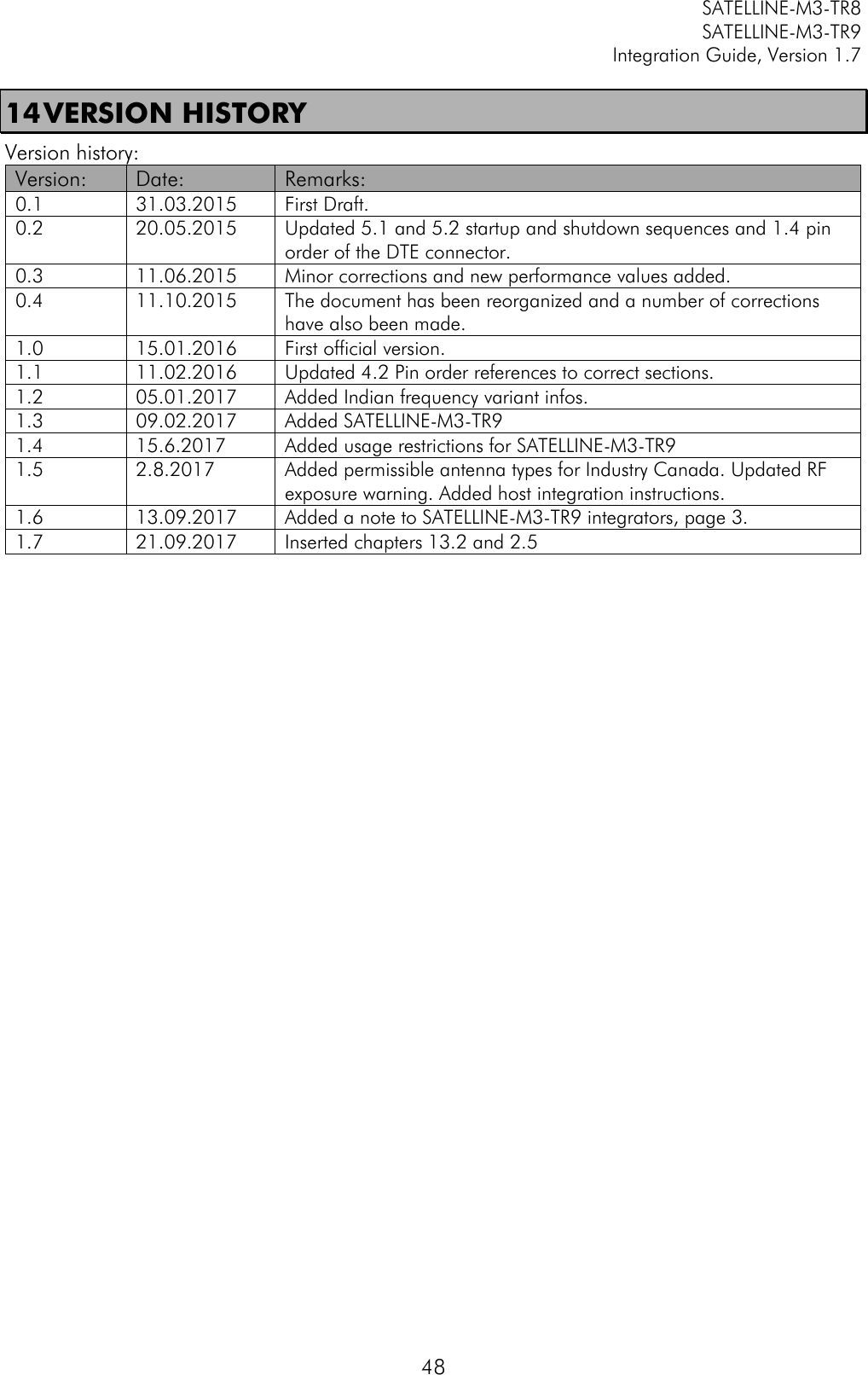
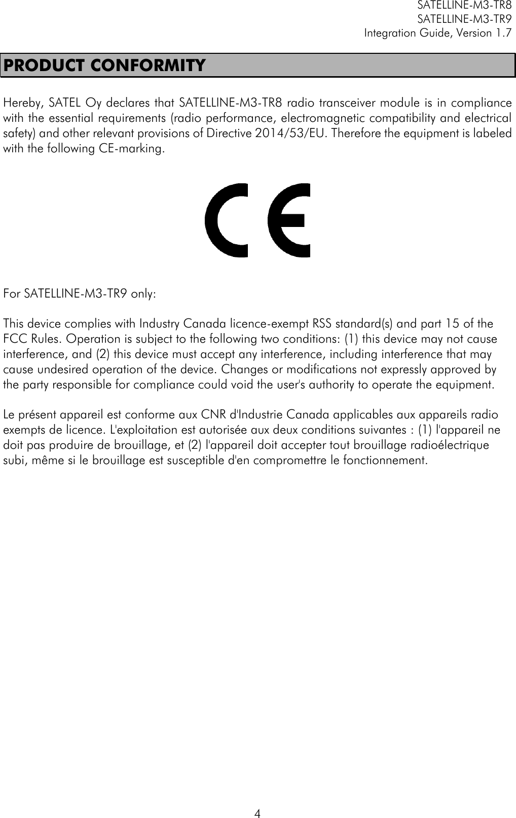
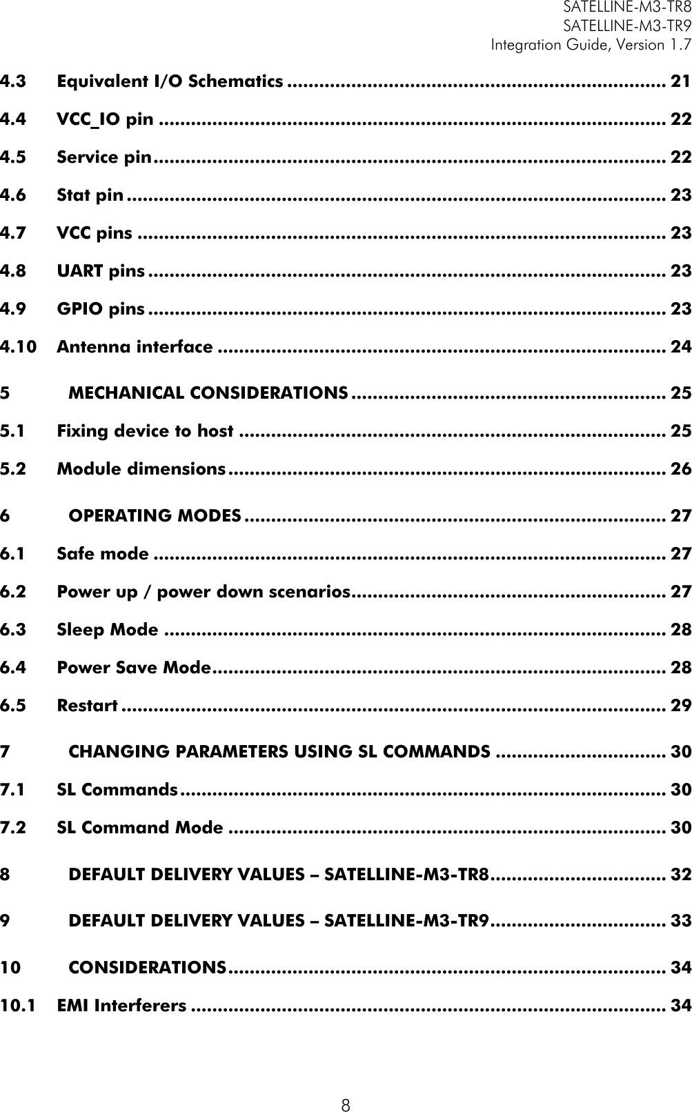
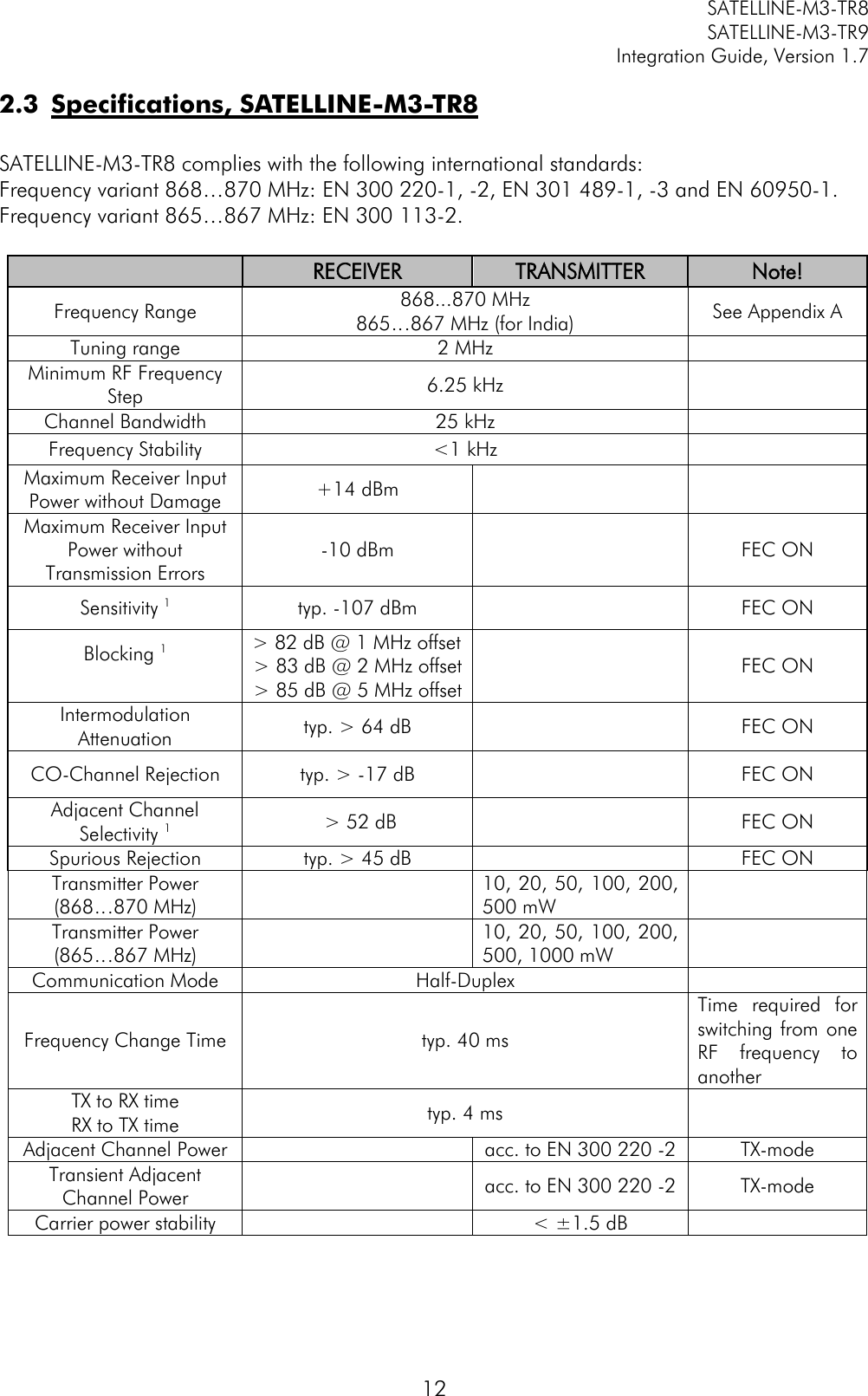
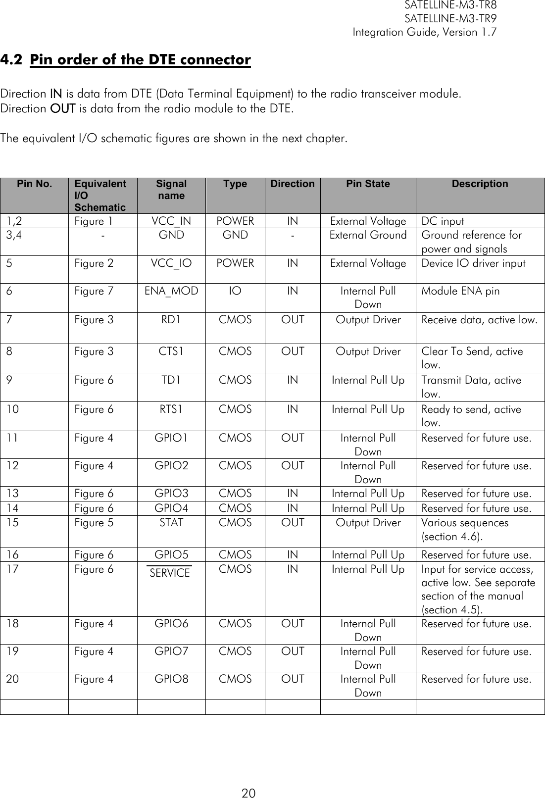
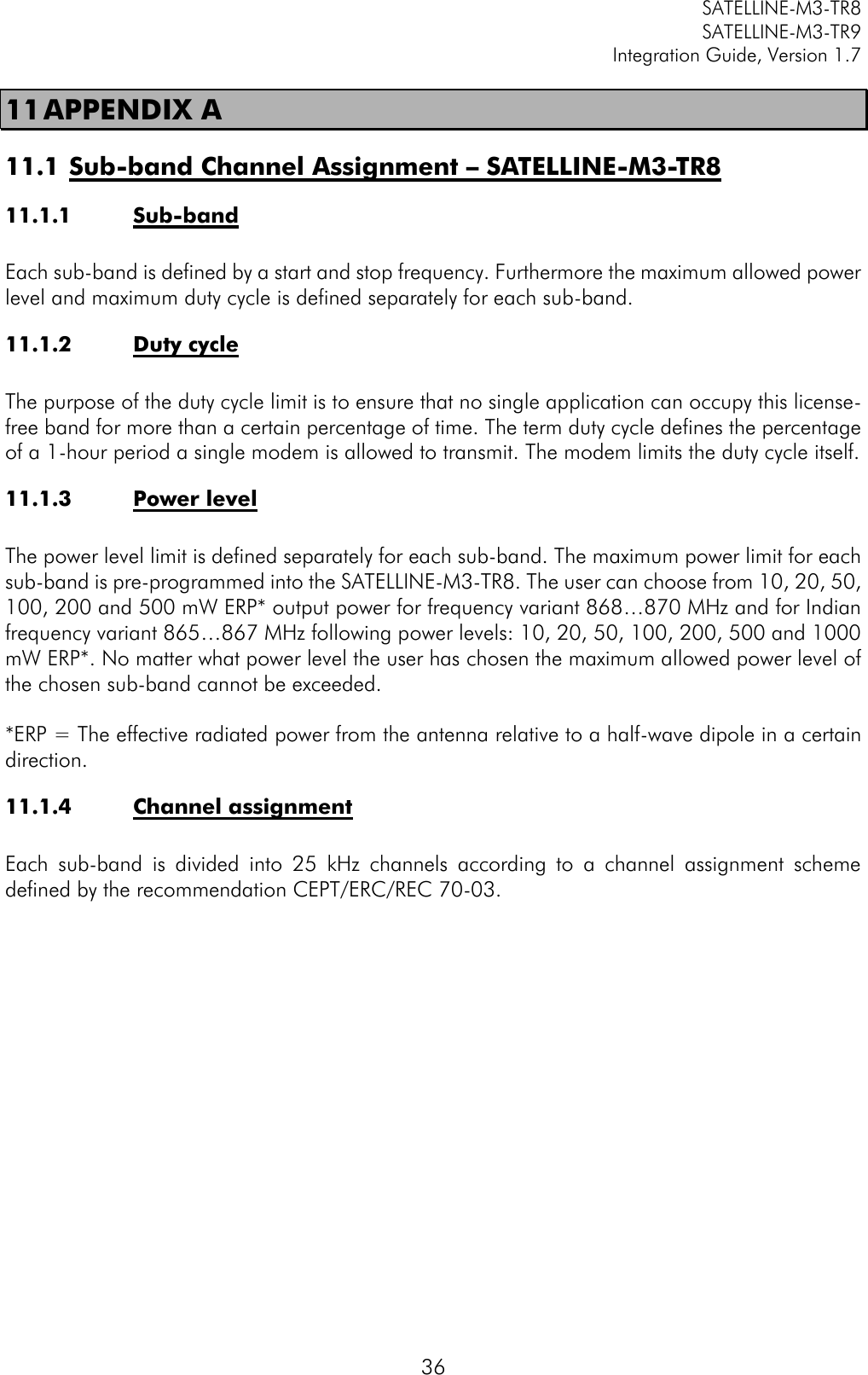
![SATELLINE-M3-TR8 SATELLINE-M3-TR9 Integration Guide, Version 1.7 38 ChannelList SL$D=n Set channel list default channel, n is channel number “OK" or "ERROR" ChannelList SL$E=1 Search free channel Modem searches for next traffic-free channel. Listening time of traffic is about 2 seconds Modem shows next free channel by activating command again "OK" followed by “channel n is free” Value of n is channel number of next free channel on channel list ChannelList SL$F? Get active channel number decimal number ChannelList SL$F=n Set modem to channel number n in channel list “OK" or "ERROR" ChannelList SL$L?nn Get channel info. Index nn=[0...(number of channels-1)] Channel number, Frequency, Channel width, Tx Power For example: "CH 1, 869.412500 MHz, 25.0 kHz, 500 mW" ChannelList SL$L=<info> Set channel info. Format is SL$L=Iaa,Nbbbbbb,Fcccccccccc,Wdddddd,Peeeee<CR> or alternatively SL$L=Iaa,Nbbbbbb,FTccc.cccccc,FRccc.cccccc,Wdd.ddd,Peeeee<CR> where capital letter marks parameter field and the following decimal number presents its value. aa = Index (0...39) bbbbbb = Channel number (-32767...32767) cccccccccc = Tx/Rx Frequency in MHz (only numbers or "." allowed, "," is not allowed) F field defines a common frequency value for Tx and Rx FT field defines Tx frequency FR field defines Rx frequency dddddd = Channel spacing/width in kHz (12.5, 20 or 25), trailing decimals are tolerated e.g. "25", "25.0", "25.00" and "25.000" are all valid) eeeee = Transmitter power in mW (0...35000) (modem rounds the value to the closest applicable) Note: 0 means "don't care" value for power. <CR> = Carriage return character “OK" or "ERROR" ChannelList SL$M? Get status of channel list. 0 = Not in use, 1 = Channel list in use "0" or "1" ChannelList SL$M=n Set status of channel list. 0 = Not in use, 1 = Channel list in use “OK" or "ERROR" ChannelList SL$R? Get listening time (seconds) of Search free channel function decimal number ChannelList SL$R=n Set listening time (seconds) of Search free channel function “OK" or "ERROR"](https://usermanual.wiki/Satel/SATEL-TA31/User-Guide-3580287-Page-39.png)
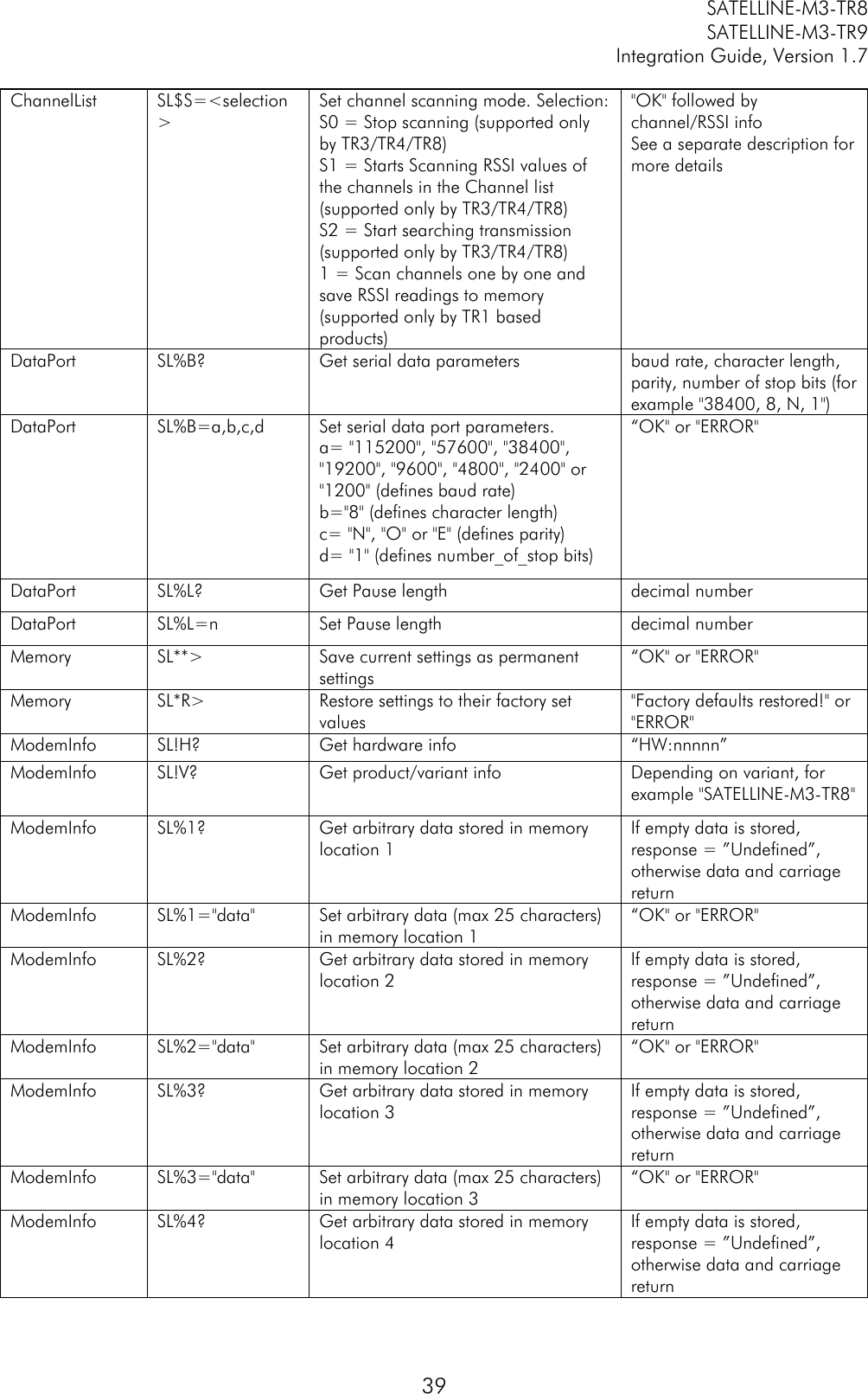
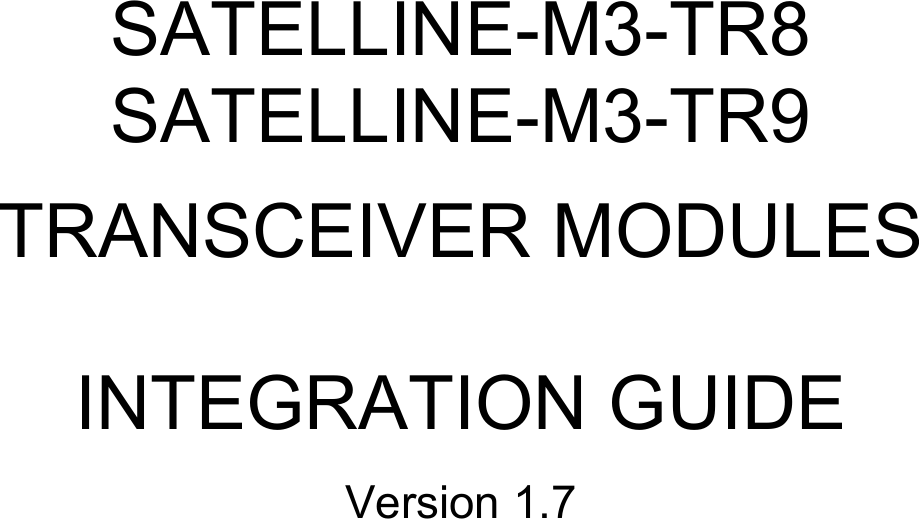
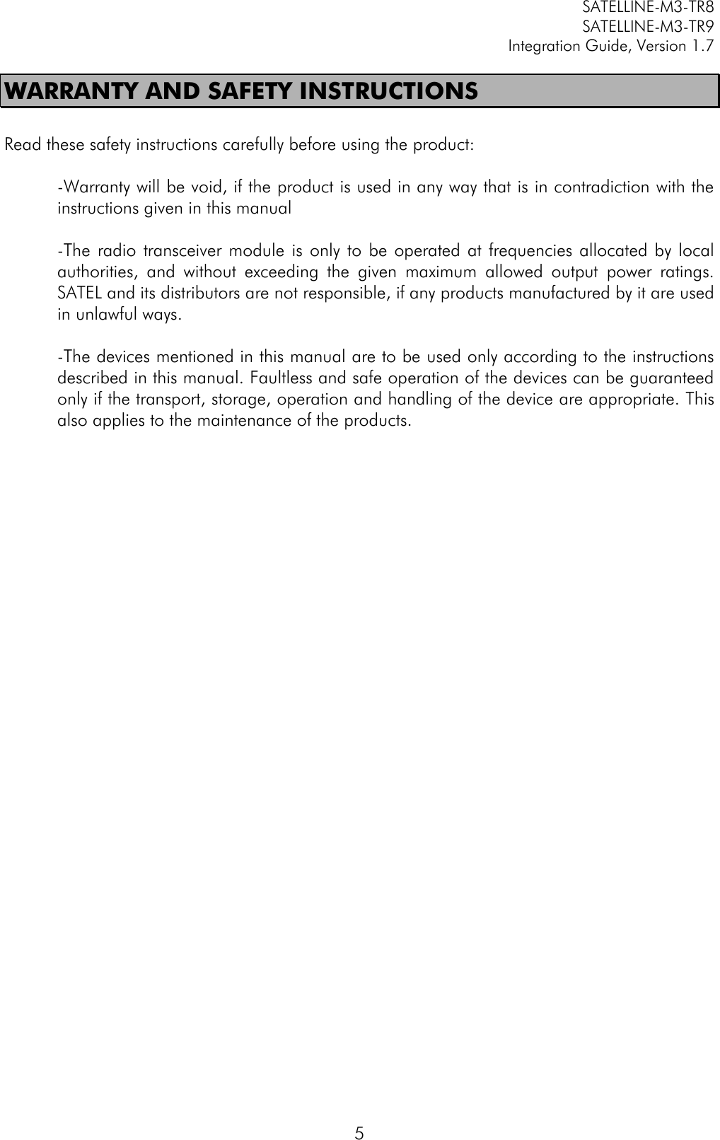
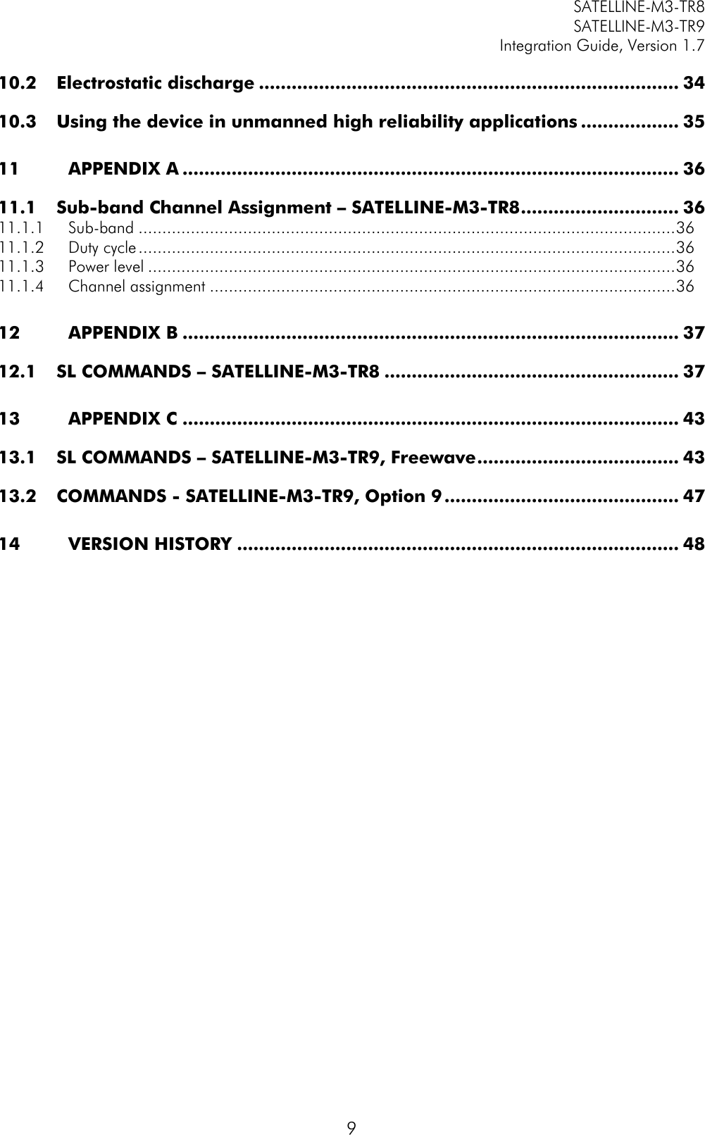
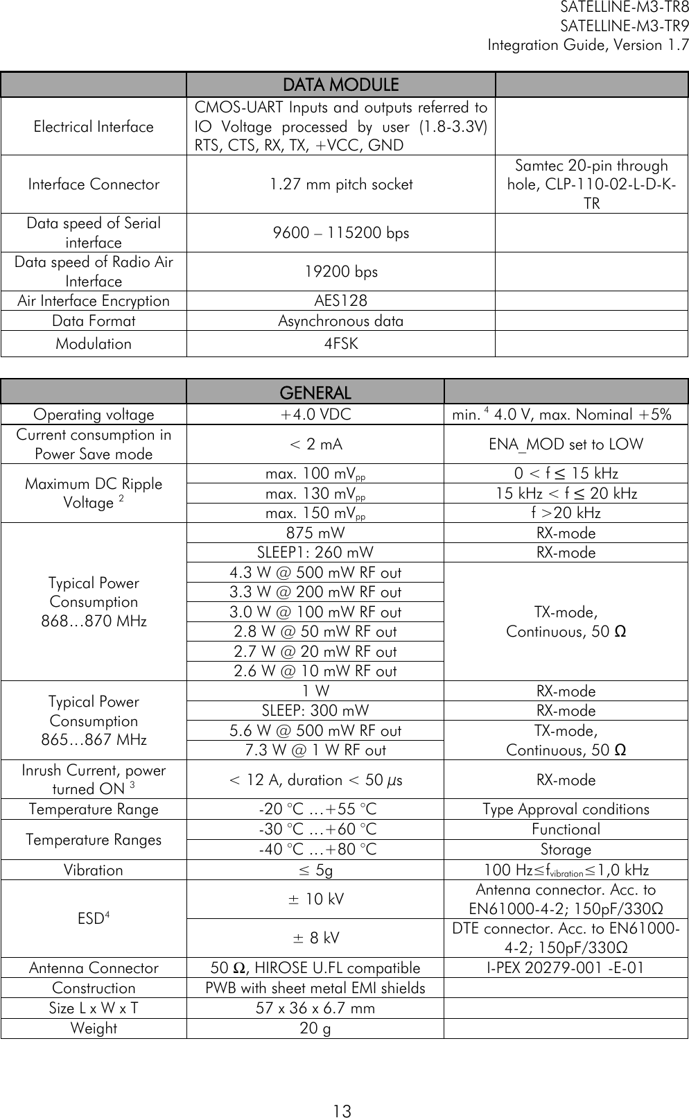
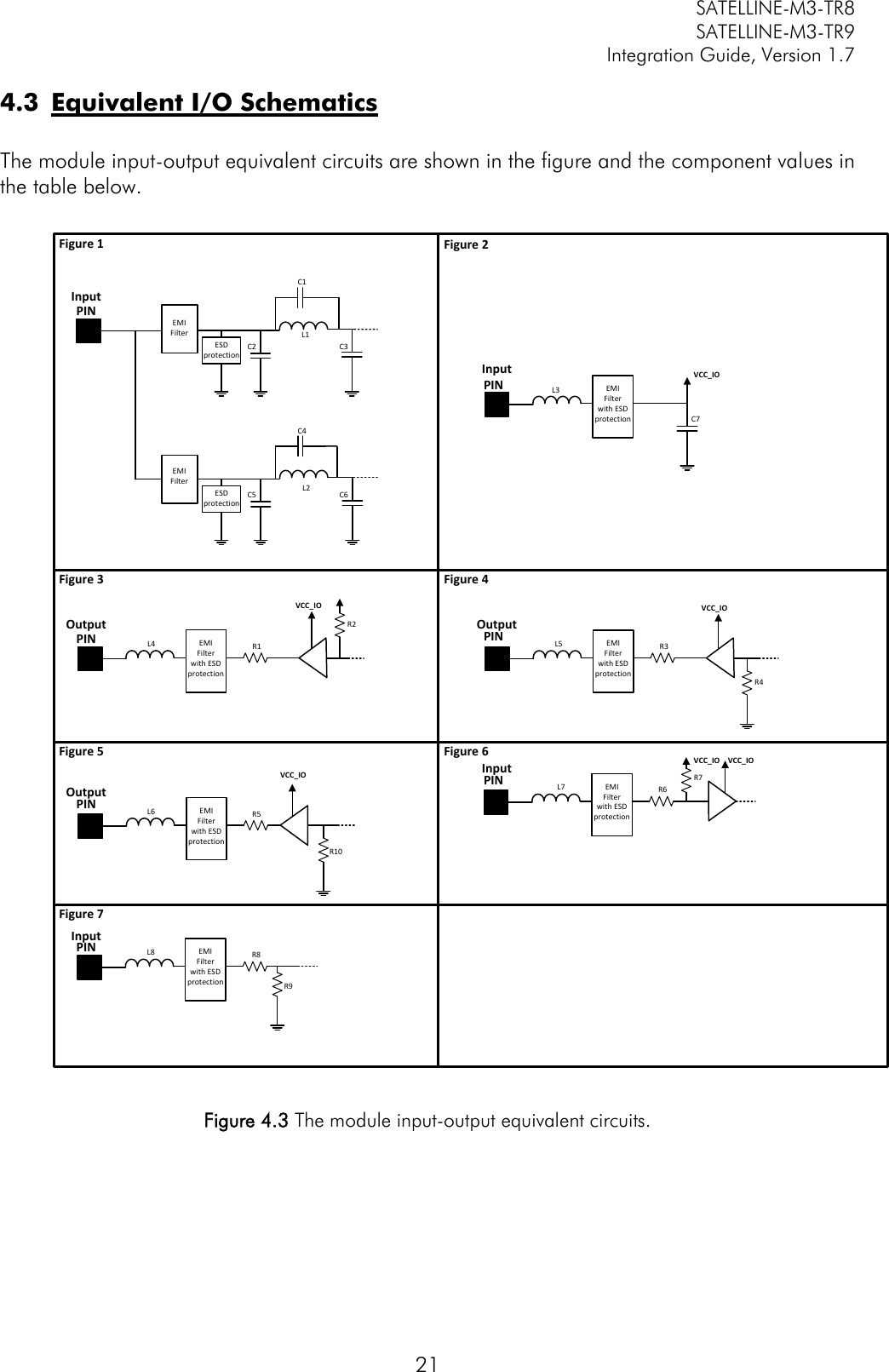
![SATELLINE-M3-TR8 SATELLINE-M3-TR9 Integration Guide, Version 1.7 40 ModemInfo SL%4="data" Set arbitrary data (max 25 characters) in memory location 4 “OK" or "ERROR" ModemInfo SL%C? Get product number (or other customer info) Depends on setup ModemInfo SL%C=”text string” Sets p/n (or other customer info) if it is empty (command works only once). P/n must be stored to eeprom with command SL**> (Save settings). Otherwise it will be lost when power is turned off “OK” or error message ModemInfo SL%D? Get product type Depends on model, for example "SATELLINE-M3-TR8" ModemInfo SL%H? Get logic hardware version Hardware info ModemInfo SL%I? Get Firmware FlashID Depends on model ModemInfo SL%R? Get Regional Info Region code number, Status of regional settings followed by CR character. Region code number 0=Default (=not set, or rest of the world), 1=US. Status of regional settings 0=Default(=undefined), 1=Valid, 2=Conflict Example: "1,2" means Region code US and the settings are in conflict to FCC ModemInfo SL%S? Get Serial Number Serial number of radio modem ModemInfo SL%V? Get firmware revision information For example "V07.22.2.3.0.2" OperationMode SL+S=x Activate sleep mode. Value of n: "1" Turn the modem into a state where it will hold parts of the radio on, wakeup will take <5ms "5" Turns ON Power Save mode (TR3/TR4 specific command) "6" Turns OFF Power Save mode (TR3/TR4 specific command) “OK” or “ERROR” RadioFreq SL!D? Get lower limit of frequency band 1 “nnn.nnnnn MHz" RadioFreq SL!U? Get upper limit of frequency band 1 ”nnn.nnnnn MHz" RadioFreq SL!W? Get lower limit of frequency band 2 ”nnn.nnnnn MHz" RadioFreq SL!Y? Get upper limit of frequency band 2 ”nnn.nnnnn MHz" RadioFreq SL&+=nnnn Set active frequency nnnn channels above center frequency. Frequency = Center frequency + nnnn*Channel spacing Value of nnnn is [0...number of channels/2] For conventional reasons, only 2 or 4 digit inputs are valid “OK" or "ERROR" RadioFreq SL&-=nnnn Set active frequency nnnn channels below center frequency. Frequency = Center frequency – nnnn*Channel spacing “OK" or "ERROR"](https://usermanual.wiki/Satel/SATEL-TA31/User-Guide-3580287-Page-41.png)
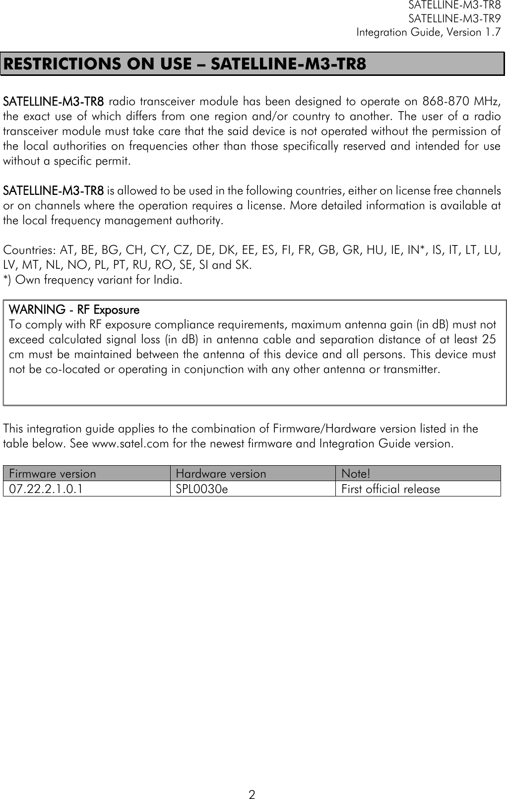
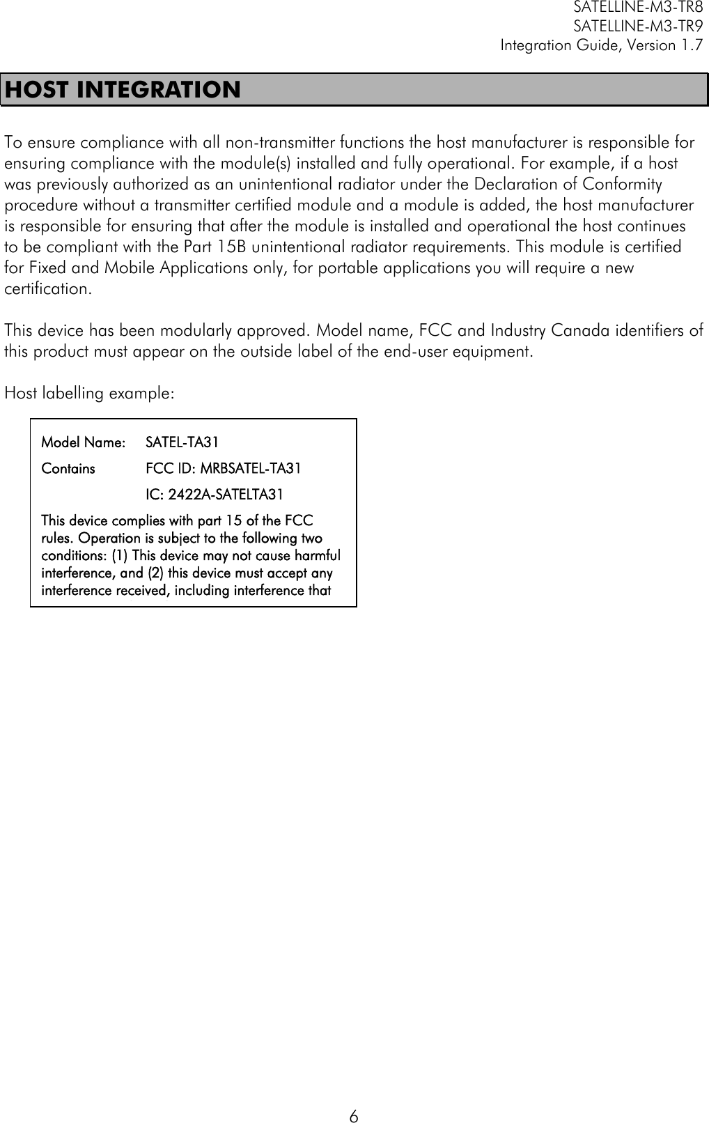
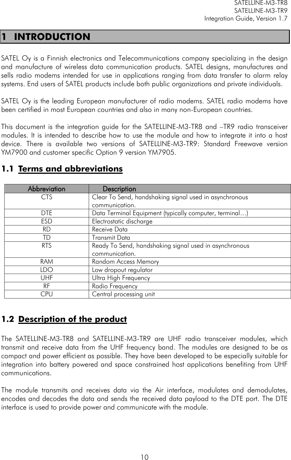
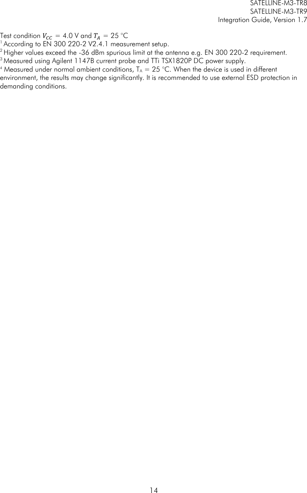
![SATELLINE-M3-TR8 SATELLINE-M3-TR9 Integration Guide, Version 1.7 41 Value of nnnn is [0…number of channels/2] For conventional reasons, only 2 or 4 digit inputs are valid RadioFreq SL&B? Get active subband Subband Number,Min Freq,Max Freq,Max Power,Duty cycle For example: "1, 869.40000 MHz, 869.65000 MHz, 500 mW, 10%" RadioFreq SL&B=z Set frequency band. Value of z is: “1” 869.4-869.65MHz, 500mW, 10% “2” 869.65-869.7MHz, 25mW, 10% “3” 869.7-870MHz, 25mW, 1% “4” 868-868.6MHz, 25mW, 1% “5” 868.6-868.7MHz, 10mW, 1% “6” 869.3-869.4MHz, 10mW, 1% “OK" or "ERROR" RadioFreq SL&C? Get center/reference frequency “nnn.nnnnn MHz” RadioFreq SL&X=nnn.nnnn Set center/reference frequency “OK" or "ERROR" RadioFreq SL&E? Get Enabled Channel Widths List of supported Channel widths e.g. "12.5 kHz, 20.0 kHz, 25.0 kHz" RadioFreq SL&F? Get active frequency TX nnn.nnnnn MHz, RX nnn.nnnnn MHz RadioFreq SL&F=nnn.nnnnn Set active frequency to nnn.nnnnn MHz “OK" or "ERROR" RadioFreq SL&FR? Get Rx frequency "nnn.nnnnn MHz" RadioFreq SL&FR=nnn.nnnnn Set Rx frequency to nnn.nnnnn MHz “OK" or "ERROR" RadioFreq SL&FT? Get Tx frequency "nnn.nnnnn MHz" RadioFreq SL&FT=nnn.nnnnn Set Tx frequency to nnn.nnnnn MHz “OK" or "ERROR" RadioFreq SL&N? Get active channel calculated from center frequency ( = (active frequency – center frequency)/channel spacing ) decimal number "+nnnn", "-nnnn", "+nn" or "-nn" RadioFreq SL&W? Get channel spacing/channel width "25.0 kHz” RadioFreq SL&W=xxxx Set channel spacing. Value of xxxx is: ”2500” for 25 kHz Command is supported only by hardware variants with adjustable channel spacing. “OK" or "ERROR" RadioProperty SL%F? Get status of Error correction (FEC) "0" = FEC OFF , "1" = FEC ON RadioProperty SL%F=x Set Error correction (FEC). Value of x is: "1" Set FEC ON "0" Set FEC OFF “OK" or "ERROR" RadioProperty SL%E? Get status of Error check and Full CRC16 check modes "0" Error check off "1" CRC8 Partial "2" CRC8 Full "3" CRC16 Full](https://usermanual.wiki/Satel/SATEL-TA31/User-Guide-3580287-Page-42.png)
![SATELLINE-M3-TR8 SATELLINE-M3-TR9 Integration Guide, Version 1.7 42 RadioProperty SL%E=x Set Error check and Full CRC16 check modes. Value of x is: "0" Error check off "1" CRC8 Partial "2" CRC8 Full "3" CRC16 Full “OK" or "ERROR" RadioProperty SL%R? Get region code setting/status 0,0 = Default, 1,1 = US, 1,2 = US & Illegal radio setting combination (TX is disabled) RadioProperty SL@D? Get Tx delay (ms) For example "0 ms" or "50 ms" RadioProperty SL@D=n Set Tx delay (ms), n is [0…65535] "OK" or "ERROR" RadioProperty SL@E? Get supported radio compatibility modes. List of numbers, separated by commas, showing the supported modes: 0=SATELLINE-3AS. RadioProperty SL@F? Get noise level of radio channel ”-xxx dBm" RadioProperty SL@M? Get repeater function "O" = Repeater OFF(character O) "R" = Repeater ON RadioProperty SL@M=x Set repeater function. Values of x are: "O" = Repeater function OFF (character O) "R" = Repeater function ON “OK" or "ERROR" RadioProperty SL@P? Get transmitter output power One of these values “10mW, “20mW”, “50mW”, "100mW", "200mW", "500mW" RadioProperty SL@P=nnnnn Set RF output power (mW) Valid values for nnnnn: "10" for 10 mW TX power. "20" for 20 mW TX power. "50" for 50 mW TX power. "100" for 100 mW TX power. "200" for 200 mW TX power. "500" for 500 mW TX power. "OK" or "ERROR" RadioProperty SL@R? Get RSSI (Received Signal Strength Indication) of last received message (dBm) ”-nnn dBm”, nnn is a decimal value of field strength between –80 dBm and –118 dBm. Value is available 7 s after reception, after that the response is "<-118 dBm". RadioProperty SL@S? Get radio compatibility mode "0" = SATELLINE-3AS RadioProperty SL@S=x Set radio compatibility mode. Value of x is: 0 = SATELLINE-3AS “OK" or "ERROR" Reset SL@X=n Reset command. Values of n are: "9" Reset modem “OK" or "ERROR", then modem resets required blocks.](https://usermanual.wiki/Satel/SATEL-TA31/User-Guide-3580287-Page-43.png)
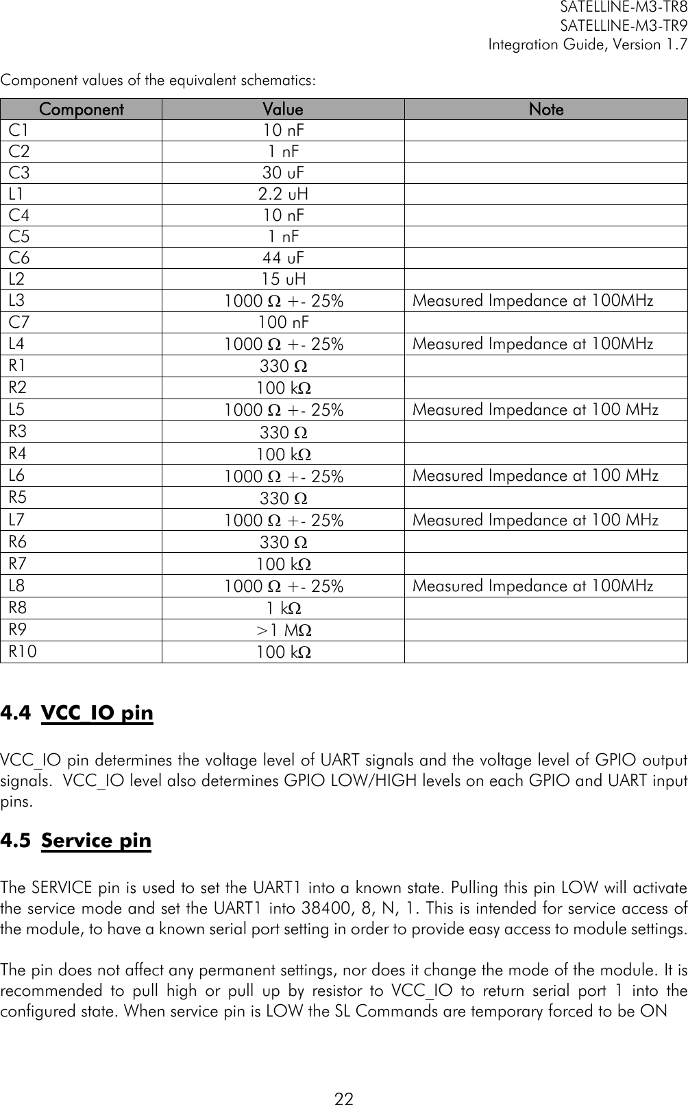
![SATELLINE-M3-TR8 SATELLINE-M3-TR9 Integration Guide, Version 1.7 43 13 APPENDIX C 13.1 SL COMMANDS – SATELLINE-M3-TR9, Freewave General format of the Freewave related SL commands is: Set Emulation mode settings: SL~E=M1,I<index>,A<Attribute1>,B<Attribute2>,C<Attribute3>,... prefix M indicates the emulation mode (M1 means Freewave, M2 means something else...) prefix I is the index indicating the specific setting under the emulation mode prefixes A, B, C, ... indicate the corresponding attributes Get Emulation setting: SL~E?M1,I<index> Format of response is M1,I<index>,A<Attribute1>,B<Attribute2>,C<Attribute3>,... Get Emulation settings summary: SL~E? Response is reserved for the summary of the emulation settings (to be defined later) Setting name Type Values (Range) Value descriptions SL Command Modem Mode Uint8 0 -7 , A-B 0: Point to Point Master 1: Point to Point Slave 2: Point to MultiPoint Master 3: Point to MultiPoint Slave 4: Point to Point Slave/Repeater 5: Point to Point Repeater 6: Point to Point Slave/Master Switchable 7: Point to Multipoint Repeater A: Mirrored Bit Master B: Mirrored Bit Slave SL~E=M1,I1,A<Mode> <Mode> = [0-7,A-B] as presented on the left Call Book Entry To Call Uint8 0 - A 0 - 9: Call Book Entry Index A: All SL~E=M1,I2,A<index> <index> = [0-9,A] as presented on the left](https://usermanual.wiki/Satel/SATEL-TA31/User-Guide-3580287-Page-44.png)
![SATELLINE-M3-TR8 SATELLINE-M3-TR9 Integration Guide, Version 1.7 44 Call Book Uint8, Uint8[3], Uint8[3], Uint8[3] 0 - 9, 0x000000 - 0xFFFFFF, 0x000000 - 0xFFFFFF, 0x000000 - 0xFFFFFF 0 - 9: Call Book Entry Index 0x000000 - 0xFFFFFF: Address 0x000000 - 0xFFFFFF: Repeater1 Address 0x000000 - 0xFFFFFF: Repeater2 Address SL~E=M1,I3,A<index>,B<Address>,C<Address>,D<Address> A indicates Call Book Entry Index field <index> = [0-9] as presented on the left B indicates Address field C indicates Repeater1 Address field D indicates Repeater2 Address field <Address> = [000000-FFFFFF] Frequency Key Uint8 0 - E 0 - E: Key for frequency hop table SL~E=M1,I4,A<Frequency Key> <Frequency Key> = [0-9,A-E] Frequency Zone Uint16 0x0000 - 0xFFFF Used to enable/disable frequency bands Bit 0: 902.2464 - 903.8592 MHz Bit 1: 904.0896 - 905.4720 MHz Bit 2: 905.7024 - 907.0848 MHz Bit 3: 907.3152 - 908.6976 MHz Bit 4: 908.9280 - 910.3104 MHz Bit 5: 910.5408 - 911.9232 MHz Bit 6: 912.1536 - 913.5360 MHz Bit 7: 913.7664 - 915.1488 MHz Bit 8: 915.3792 - 916.7616 MHz Bit 9: 916.9920 - 918.6048 MHz Bit 10: 918.8352 - 920.2176 MHz Bit 11: 920.4480 - 921.8304 MHz Bit 12: 922.0608 - 923.4432 MHz Bit 13: 923.6736 - 925.0560 MHz Bit 14: 925.2864 - 926.6688 MHz Bit 15: 926.8992 - 927.8208 MHz SL~E=M1,I5,A<Frequency Zone> <Frequency Zone> = [0000...FFFF], each bit enables (1) or disables (0) the corresponding frequency band as defined on the left](https://usermanual.wiki/Satel/SATEL-TA31/User-Guide-3580287-Page-45.png)
![SATELLINE-M3-TR8 SATELLINE-M3-TR9 Integration Guide, Version 1.7 45 Hop Table Version Uint8 0 - 6 0: 902 - 928 MHz 1: 915 - 928 MHz 2: 902 - 928 MHz, 16 fewer freqs 3: 916 - 920 MHz 4: 921 - 928 MHz 5: 902 - 911 & 919 - 928 MHz 6: 902 - 915 MHz SL~E=M1,I6,A<Hop Table Version> <Hop Table Version> = [0-6] as presented on the left Hop Table Size Uint8 50 - 112 50 - 112: Number of different frequencies in hop table SL~E=M1,I7,A<Number of different frequencies in hop table> <Number of different frequencies in hop table> = [50-112] Max Packet Size Uint8 0 - 9 0 - 9: Defines maximum packet size in transmit SL~E=M1,I8,A<Max Packet Size> <Max Packet Size> = [0-9] Min Packet Size Uint8 0 - 9 0 - 9: Defines minimum packet size in transmit SL~E=M1,I9,A<Max Packet Size> <Max Packet Size> = [0-9] Transmit Rate Boolean 0 - 1 0: Diagnostics 1: Normal SL~E=M1,I10,A<Transmit Rate> <Transmit Rate> = 0 (=Diagnostics) or 1 (=Normal) RF Data Rate Uint8 2 - 3 2: High 3: Normal SL~E=M1,I11,A<RF Data Rate> <RF Data Rate> = 2 (=High) or 3(=Normal) Transmit Power Uint8 10-1000 10 mW 20 mW 50 mW 100 mW 200 mW 500 mW 1000 mW GET: SL@P? SET: SL@P= Slave Security Boolean 0 - 1 0: On 1: Off SL~E=M1,I12,A<Slave Security> <RF Data Rate> = 2 (=High) or 3(=Normal) RTS To CTS Uint8 0 - 2 0: Disabled 1: Enabled 2: ??? SL~E=M1,I13,A<RTS To CTS> <RTS To CTS> = 0 (=Disabled), 1 (=Enabled) or 2 (don't care?) Retry Timeout Uint8 8 - 255 8 - 255: Counter value when connection is dropped off if data is not received. SL~E=M1,I14,A<Retry Timeout> <Retry Timeout> = [8-255] Repeaters Boolean 0: Disabled 1: Enabled SL~E=M1,I15,A<Repeaters> <Repeaters> = 0 (=Disabled), 1 (=Enabled) or 2 (don't care?) Master Packet Repeat Uint8 0 - 9 0 - 9: Defines how many times master will send packets SL~E=M1,I16,A<Master Packet Repeat> <Master Packet Repeat> = [0-9] Max Slave Retry Uint8 0 - 9 0 - 9: Defines how many times slave try to transmit data if ack is not received SL~E=M1,I17,A<Max Slave Retry> <Max Slave Retry> = [0-9]](https://usermanual.wiki/Satel/SATEL-TA31/User-Guide-3580287-Page-46.png)
![SATELLINE-M3-TR8 SATELLINE-M3-TR9 Integration Guide, Version 1.7 46 Retry Odds Uint8 0 - 9 0 - 9: Defines a random base when slave is trying to resend data to master if Max Slave Retry count is reached. Value 0 means that the slave's data buffer is purged after Max Slave Retry count is reached SL~E=M1,I18,A<Retry Odds> <Retry Odds> = [0-9] Repeater Frequency Boolean 0 - 1 0: Disabled 1: Enabled SL~E=M1,I19,A<Repeater Frequency> <Repeater Frequency> = 0 (=Disabled) or 1 (=Enabled) Network ID Uint16 0 - 4095 0 - 4095: Network ID for multipoint networks. Network ID 255 = Call Book Mode SL~E=M1,I20,A<Network ID> <Network ID> = [0-4095] Note: Network ID 255 = Call Book Mode Slave/Repeater Boolean 0: Disabled 1: Enabled SL~E=M1,I21,A<Slave/Repeater> <Slave/Repeater> = 0 (=Disabled) or 1 (=Enabled) TX Subnet Uint8 0 - 9, A - F 0: Roaming 1 - E: Subnet ID F: Disabled SL~E=M1,I22,A<TX Subnet> <TX Subnet> = [0-9, A-F] as presented on the left RX Subnet Uint8 0 - 9, A - F 0: Roaming 1 - E: Subnet ID F: Disabled SL~E=M1,I23,A<RX Subnet> <RX Subnet> = [0-9, A-F] as presented on the left Serial port settings GET: SL%B? SET: SL%B=](https://usermanual.wiki/Satel/SATEL-TA31/User-Guide-3580287-Page-47.png)