Satel SATELLINE-3AS Radio Data Modem User Manual 3AS TC user guide
Satel Oy Radio Data Modem 3AS TC user guide
UserManual.wiki
>
Satel
>
SATELLINE-3AS User Manual
>
3AS TC user guide
Contents
1.
8
2.
3AS TC user guide
3AS TC user guide
Navigation menu
Upload a User Manual
Namespaces
Wiki Guide
HTML
PDF
Info
Views
User Manual
Discussion / Help
Navigation

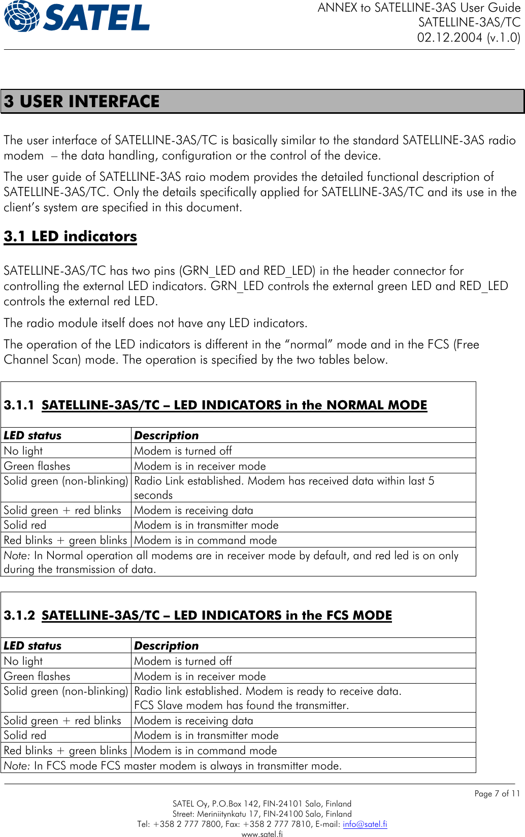
![ANNEX to SATELLINE-3AS User Guide SATELLINE-3AS/TC 02.12.2004 (v.1.0) Page 8 of 11 SATEL Oy, P.O.Box 142, FIN-24101 Salo, Finland Street: Meriniitynkatu 17, FIN-24100 Salo, Finland Tel: +358 2 777 7800, Fax: +358 2 777 7810, E-mail: info@satel.fi www.satel.fi 3.2 SL commands SATELLINE-3AS/TC accepts the same SL commands as SATELLINE-3AS. The table below lists all commands available. 3.2.1 SATELLINE-3AS – SL COMMANDS LIST Frequency related Effect and description of command SL&F=nnn.nnnnn Set frequency to nnn.nnnnn MHz SL&F? Display current frequency (response 'nnn.nnnnn MHz') SL&C? Display center frequency (response 'nnn.nnnnn MHz') SL&+=nn Set frequency nn channels above center frequency Frequency = Center frequency + nn * Channel spacing, where nn=[0...Number of channels/2] SL&-=nn Set frequency nn channels below center frequency Frequency = Center frequency – nn * Channel spacing, where nn=[0…Number of channels/2] SL&N? Display current frequency deviation from center frequency as channels (Frequency – Center frequency)/Channel spacing (response ‘+nn’ or ‘-nn’) SL&D=x Sets the operational mode of the radio. The different values of x are: ”S” = Single Channel ”D” = Dual Channel ”R” = Reverse Dual Channel Note! Use this command only, if the setup of the frequency bands matches the Dual Channel operation. SL&D? Request the operational mode of the radio. The response is one of the following: ”S” = Single Channel ”D” = Dual Channel ”R” = Reverse Dual Channel Note! Use this command only, if the setup of the frequency bands matches the Dual Channel operation. Addressing related Effect and description of command (These commands are NOT applicable in this application) SL#I=xxxx Set all addresses (RX1, RX2, TX1, TX2) to value xxxx SL#I? Display both primary addresses (TX1, RX1) (response ’xxxx;yyyy’) SL#T=xxxx Set both transmit addresses (TX1, TX2) to value xxxx SL#T? Display primary transmit address (TX1) (response ‘xxxx’) SL#R=xxxx Set both receive addresses (RX1, RX2) to value xxxx SL#R? Display primary receive address (RX1) (response ‘xxxx’) SL#P=xxxx;yyyy Set primary transmit address (TX1) to value xxxx and receive address (RX1) to value yyyy SL#S=xxxx;yyyy Set secondary transmit address (TX2) to value xxxx and receive address (RX2) to value yyyy SL#P? Display primary transmit address (TX1) and receive address (RX1) (response ‘xxxx;yyyy’) SL#S? Display secondary transmit address (TX2) and receive address (RX2) (response ‘xxxx;yyyy’) Note: xxxx and yyyy above mean address in the hexadecimal format (0000 … FFFF)](https://usermanual.wiki/Satel/SATELLINE-3AS.3AS-TC-user-guide/User-Guide-510172-Page-8.png)